

Page 1

17" Floor Model
Drill Press
Perceuse à
colonne de
17-959L
432 mm (17 po),
modèle sur pied
Prensa de taladro
de 432 mm (17"),
modelo de apoyo
sobre el suelo
Instruction Manual
Manuel d’Utilisation
Manual de Instrucciones
FRANÇAIS (21) ESPAÑOL (39)
www.deltamachinery.com
(800) 223-7278 - US
(800) 463-3582 - CANADA
Page 2

TABLE OF CONTENTS
IMPORTANT SAFETY INSTRUCTIONS . . . . . . . . . . . . . . . . . . . . . . . . . . . . . . . . . . . . . . . . . . . . . . . . . . . . . . . . . . . 2
SAFETY GUIDELINES. . . . . . . . . . . . . . . . . . . . . . . . . . . . . . . . . . . . . . . . . . . . . . . . . . . . . . . . . . . . . . . . . . . . . . . . . 3
GENERAL SAFETY RULES . . . . . . . . . . . . . . . . . . . . . . . . . . . . . . . . . . . . . . . . . . . . . . . . . . . . . . . . . . . . . . . . . . . . 4
ADDITIONAL SPECIFIC SAFETY RULES . . . . . . . . . . . . . . . . . . . . . . . . . . . . . . . . . . . . . . . . . . . . . . . . . . . . . . . . . 5
FUNCTIONAL DESCRIPTION . . . . . . . . . . . . . . . . . . . . . . . . . . . . . . . . . . . . . . . . . . . . . . . . . . . . . . . . . . . . . . . . . . 7
CARTON CONTENTS . . . . . . . . . . . . . . . . . . . . . . . . . . . . . . . . . . . . . . . . . . . . . . . . . . . . . . . . . . . . . . . . . . . . . . . . . 8
ASSEMBLY . . . . . . . . . . . . . . . . . . . . . . . . . . . . . . . . . . . . . . . . . . . . . . . . . . . . . . . . . . . . . . . . . . . . . . . . . . . . . . . . . 9
OPERATION . . . . . . . . . . . . . . . . . . . . . . . . . . . . . . . . . . . . . . . . . . . . . . . . . . . . . . . . . . . . . . . . . . . . . . . . . . . . . . . 13
TROUBLESHOOTING . . . . . . . . . . . . . . . . . . . . . . . . . . . . . . . . . . . . . . . . . . . . . . . . . . . . . . . . . . . . . . . . . . . . . . . 19
MAINTENANCE. . . . . . . . . . . . . . . . . . . . . . . . . . . . . . . . . . . . . . . . . . . . . . . . . . . . . . . . . . . . . . . . . . . . . . . . . . . . . 19
SERVICE . . . . . . . . . . . . . . . . . . . . . . . . . . . . . . . . . . . . . . . . . . . . . . . . . . . . . . . . . . . . . . . . . . . . . . . . . . . . . . . . . . 19
ACCESSORIES . . . . . . . . . . . . . . . . . . . . . . . . . . . . . . . . . . . . . . . . . . . . . . . . . . . . . . . . . . . . . . . . . . . . . . . . . . . . . 20
WARRANTY. . . . . . . . . . . . . . . . . . . . . . . . . . . . . . . . . . . . . . . . . . . . . . . . . . . . . . . . . . . . . . . . . . . . . . . . . . . . . . . . 20
FRANÇAIS . . . . . . . . . . . . . . . . . . . . . . . . . . . . . . . . . . . . . . . . . . . . . . . . . . . . . . . . . . . . . . . . . . . . . . . . . . . . . . . . . 21
ESPAÑOL. . . . . . . . . . . . . . . . . . . . . . . . . . . . . . . . . . . . . . . . . . . . . . . . . . . . . . . . . . . . . . . . . . . . . . . . . . . . . . . . . . 39
IMPORTANT SAFETY INSTRUCTIONS
Read and understand all warnings and operating instructions before using any tool or equipment.
When using tools or equipment, basic safety precautions should always be followed to reduce the risk of
personal injury. Improper operation, maintenance or modification of tools or equipment could result in serious
injury and property damage. There are certain applications for which tools and equipment are designed. DELTA
Machinery strongly recommends that this product NOT be modified and/or used for any application other than
for which it was designed.
If you have any questions relative to its application DO NOT use the product until you have written DELTA
Machinery and we have advised you.
Online contact form at www.deltamachinery.com
Postal Mail: Technical Service Manager
DELTA Machinery
4825 Highway 45 North
Jackson, TN 38305
(IN CANADA: 125 Mural St. Suite 300, Richmond Hill, ON, L4B 1M4)
Information regarding the safe and proper operation of this tool is available from the following sources:
Power Tool Institute
1300 Sumner Avenue, Cleveland, OH 44115-2851
www.powertoolinstitute.org
1121 Spring Lake Drive, Itasca, IL 60143-3201
American National Standards Institute, 25 West 43rd Street, 4 floor, New York, NY 10036 www.ansi.org
ANSI 01.1 Safety Requirements for Woodworking Machines, and the U.S. Department of Labor regulations www.osha.gov
National Safety Council
SAVE THESE INSTRUCTIONS!
2
Page 3

SAFETY GUIDELINES – DEFINITIONS
It is important for you to read and understand this manual. The information it contains relates to protecting
YOUR SAFETY and PREVENTING PROBLEMS. The symbols below are used to help you recognize this
information.
indicates an imminently hazardous situation which, if not avoided, will result in death or serious injury.
indicates a potentially hazardous situation which, if not avoided, could result in death or serious injury.
indicates a potentially haz ard ous situation which, if not avoided, may result in minor or mod er ate injury.
NOTICE
damage.
indicates a practice not related to personal injury which, if not avoided, may result in property
CALIFORNIA PROPOSITION 65
Some dust created by power sanding, sawing, grinding, drilling, and other construction activities
contains chemicals known to the State of California to cause cancer, birth defects or other reproductive harm.
Some examples of these chemicals are:
• Lead from lead-based paints,
• Crystalline silica from bricks and cement and other masonry products, and
• Arsenic and chromium from chemically-treated lumber (CCA).
Your risk from these exposures varies, depending on how often you do this type of work. To reduce your exposure to
these chemicals: work in a well-ventilated area, and work with approved safety equipment, such as those dust masks
that are specially designed to filter out microscopic particles.
3
Page 4

GENERAL SAFETY RULES
Failure to follow these rules may result in serious personal injury.
1. FOR YOUR OWN SAFETY, READ THE INSTRUCTION
MANUAL BEFORE OPERATING THE MACHINE. Learning
the machine’s application, limitations, and specific hazards
will greatly minimize the possibility of accidents and injury.
2. WEAR EYE AND HEARING PROTECTION. ALWAYS
USE SAFETY GLASSES. Everyday eyeglasses are NOT
safety glasses. USE CERTIFIED SAFETY EQUIPMENT.
Eye protection equipment should comply with ANSI Z87.1
standards. Hearing equipment should comply with ANSI
S3.19 standards.
3. WEAR PROPER APPAREL. Do not wear loose clothing,
gloves, neckties, rings, bracelets, or other jewelry which may
get caught in moving parts. Nonslip protective footwear is
recommended. Wear protective hair covering to contain long
hair.
4. DO NOT USE THE MACHINE IN A DANGEROUS
ENVIRONMENT. The use of power tools in damp or wet
locations or in rain can cause shock or electrocution. Keep
your work area well-lit to prevent tripping or placing arms,
hands, and fingers in danger.
5. MAINTAIN ALL TOOLS AND MACHINES IN PEAK
CONDITION. Keep tools sharp and clean for best and safest
performance. Follow instructions for lubricating and changing
accessories. Poorly maintained tools and machines can further
damage the tool or machine and/or cause injury.
6. CHECK FOR DAMAGED PARTS. Before using the machine,
check for any damaged parts. Check for alignment of moving
parts, binding of moving parts, breakage of parts, and any
other conditions that may affect its operation. A guard or any
other part that is damaged should be properly repaired or
replaced with DELTA or factory authorized replacement parts.
Damaged parts can cause further damage to the machine
and/or injury.
7. KEEP THE WORK AREA CLEAN. Cluttered areas and benches
invite accidents.
8. KEEP CHILDREN AND VISITORS AWAY. Your shop is a
potentially dangerous environment. Children and visitors can be
injured.
9. REDUCE THE RISK OF UNINTENTIONAL STARTING. Make
sure that the switch is in the “OFF” position before plugging
in the power cord. In the event of a power failure, move the
switch to the “OFF” position. An accidental start-up can
cause injury. Do not touch the plug’s metal prongs when
unplugging or plugging in the cord.
10. USE THE GUARDS. Check to see that all guards are in place,
secured, and working correctly to prevent injury.
11. REMOVE ADJUSTING KEYS AND WRENCHES BEFORE
STARTING THE MACHINE. Tools, scrap pieces, and other
debris can be thrown at high speed, causing injury.
12. USE THE RIGHT MACHINE. Don’t force a machine or
an attachment to do a job for which it was not designed.
Damage to the machine and/or injury may result.
13. USE RECOMMENDED ACCESSORIES. The use of
accessories and attachments not recommended by DELTA
may cause damage to the machine or injury to the user.
14. USE THE PROPER EXTENSION CORD. Make sure your
extension cord is in good condition. When using an extension
cord, be sure to use one heavy enough to carry the current
your product will draw. An undersized cord will cause a drop
in line voltage, resulting in loss of power and overheating. See
the Extension Cord Chart for the correct size depending on
the cord length and nameplate ampere rating. If in doubt, use
the next heavier gauge. The smaller the gauge number, the
heavier the cord.
15. SECURE THE WORKPIECE. Use clamps or a vise to hold the
workpiece when practical. Loss of control of a workpiece can
cause injury.
16. FEED THE WORKPIECE AGAINST THE DIRECTION OF
THE ROTATION OF THE BLADE, CUTTER, OR ABRASIVE
SURFACE. Feeding it from the other direction will cause the
workpiece to be thrown out at high speed.
17. DON’T FORCE THE WORKPIECE ON THE MACHINE.
Damage to the machine and/or injury may result.
18. DON’T OVERREACH. Loss of balance can make you fall into
a working machine, causing injury.
19. NEVER STAND ON THE MACHINE. Injury could occur if the tool
tips, or if you accidentally contact the cutting tool.
20. NEVER LEAVE THE MACHINE RUNNING UNATTENDED.
TURN THE POWER OFF. Don’t leave the machine until it comes
to a complete stop. A child or visitor could be injured.
21. TURN THE MACHINE “OFF”, AND DISCONNECT THE
MACHINE FROM THE POWER SOURCE before installing
or removing accessories, changing cutters, adjusting or
changing set-ups. When making repairs, be sure to lock the
start switch in the “OFF” position. An accidental start-up can
cause injury.
22. MAKE YOUR WORKSHOP CHILDPROOF WITH
PADLOCKS, MASTER SWITCHES, OR BY REMOVING
STARTER KEYS. The accidental start-up of a machine by a
child or visitor could cause injury.
23. STAY ALERT, WATCH WHAT YOU ARE DOING, AND
USE COMMON SENSE. DO NOT USE THE MACHINE
WHEN YOU ARE TIRED OR UNDER THE INFLUENCE
OF DRUGS, ALCOHOL, OR MEDICATION. A moment of
inattention while operating power tools may result in injury.
24. USE OF THIS TOOL CAN GENERATE
AND DISPERSE DUST OR OTHER AIRBORNE
PARTICLES, INCLUDING WOOD DUST, CRYSTALLINE
SILICA DUST AND ASBESTOS DUST. Direct particles away
from face and body. Always operate tool in well ventilated
area and provide for proper dust removal. Use dust collection
system wherever possible. Exposure to the dust may cause
serious and permanent respiratory or other injury, including
silicosis (a serious lung disease), cancer, and death. Avoid
breathing the dust, and avoid prolonged contact with dust.
Allowing dust to get into your mouth or eyes, or lay on your
skin may promote absorption of harmful material. Always use
properly fitting NIOSH/OSHA approved respiratory protection
appropriate for the dust exposure, and wash exposed areas
with soap and water.
4
Page 5

ADDITIONAL SPECIFIC SAFETY RULES
FAILURE TO FOLLOW THESE RULES MAY RESULT IN SERIOUS INJURY.
1. DO NOT OPERATE THIS MACHINE until it is completely
assembled and installed according to the instructions. A
machine incorrectly assembled can cause serious injury.
2. OBTAIN ADVICE from your supervisor, instructor, or
another qualified person if you are not thoroughly familiar
with the operation of this machine. Knowledge is safety.
3. FOLLOW ALL WIRING CODES and recommended
electrical connections to prevent shock or electrocution.
4. SECURE THE MACHINE TO A SUPPORTING SURFACE.
Vibration can cause the machine to slide, walk, or tip over.
5. NEVER START THE MACHINE BEFORE CLEARING
THE TABLE OF ALL OBJECTS (tools, scrap pieces,
etc.). Debris can be thrown at high speed.
6. NEVER START THE MACHINE with the drill bit, cutting
tool, or sanding drum against the workpiece. Loss of
control of the workpiece can cause serious injury.
7. PROPERLY LOCK THE DRILL BIT, CUTTING TOOL, OR
SANDING DRUM IN THE CHUCK before operating this
machine.
8. REMOVE THE CHUCK KEY BEFORE STARTING THE
MACHINE. The chuck key can be thrown out at a high
speed.
9. TIGHTEN ALL LOCK HANDLES before starting the
machine. Loss of control of the workpiece can cause
serious injury.
10. USE ONLY DRILL BITS, CUTTING TOOLS, SANDING
DRUMS, OR OTHER ACCESSORIES with shank size
recommended in your instruction manual. The wrong
size accessory can cause damage to the machine and/or
serious injury.
11. USE ONLY DRILL BITS, CUTTING TOOLS, OR
SANDING DRUMS that are not damaged. Damaged
items can cause malfunctions that lead to injuries.
12. USE RECOMMENDED SPEEDS for all operations. Other
speeds may cause the machine to malfunction causing
damage to the machine and/or serious injury.
13. AVOID AWKWARD OPERATIONS AND HAND
POSITIONS. A sudden slip could cause a hand to move
into the bit.
14. KEEP ARMS, HANDS, AND FINGERS away from the bit.
Serious injury to the hand can occur.
15. HOLD THE WORKPIECE FIRMLY AGAINST THE
TABLE. Do not attempt to drill a workpiece that does
not have a flat surface against the table, or that is not
secured by a vise. Prevent the workpiece from rotating
by clamping it to the table or by securing it against the
drill press column. Loss of control of the workpiece can
cause serious injury.
16. TURN THE MACHINE “OFF” AND WAIT FOR THE DRILL
BIT, CUTTING TOOL, OR SANDING DRUM TO STOP
TURNING prior to cleaning the work area, removing
debris, removing or securing workpiece, or changing
the angle of the table. A moving drill bit, cutting tool, or
sanding drum can cause serious injury.
17. PROPERLY SUPPORT LONG OR WIDE workpieces.
Loss of control of the workpiece can cause severe injury.
18. NEVER PERFORM LAYOUT, ASSEMBLY OR SET-UP
WORK on the table/work area when the machine is
running. Serious injury can result.
19. TURN THE MACHINE “OFF”, disconnect the machine
from the power source, and clean the table/work area
before leaving the machine. LOCK THE SWITCH IN THE
“OFF” POSITION to prevent unauthorized use. Someone
else might accidentally start the machine and cause
serious injury to themselves.
20. ADDITIONAL INFORMATION regarding the safe and
proper operation of power tools (i.e., a safety video)
is available from the Power Tool Institute, 1300
Sumner Avenue, Cleveland, OH 44115-2851 (www.
powertoolinstitute.com). Information is also available
from the National Safety Council, 1121 Spring Lake
Drive, Itasca, IL 60143-3201. Please refer to the
American National Standards Institute ANSI 01.1 Safety
Requirements for Woodworking Machines and the
U.S. Department of Labor OSHA 1910.213 Regulations.
ADDITIONAL SAFETY RULES FOR THE LASER
EYE INJURY – LASER LIGHT
Do not stare into beam aperture, or into a reflection from a mirror-like surface.
Do not use optical tools such as a telescope or transit to view the laser beam.
EYE INJURY – LASER LIGHT
Do not operate the laser around children or allow children to operate the laser.
Store idle laser out of reach of children and other untrained persons.
Turn the laser off when it is not in use.
Do not disassemble laser module. The class II laser output could be exceeded if the unit is disassembled. Laser complies with 21
CFR 1040.10 and 1040.11.
hazardous radiation exposure.
flammable liquids, gases, or dust. A spark could ignite the dust or fumes.
NOTE: Do not remove or deface warning labels.
Use of controls or adjustments or performance of procedures other than those specified herein may result in
EXPLOSION HAZARD. Do not operate the laser or drill press in explosive atmospheres such as in the presence of
5
Page 6
POWER CONNECTIONS
A separate electrical circuit should be used for your machines. This circuit should not be less than #12 wire and should
be protected with a 20 Amp time lag fuse. If an extension cord is used, use only 3-wire extension cords which have
3-prong grounding type plugs and matching receptacle which will accept the machine’s plug. Before connecting the
machine to the power line, make sure the switch is in the “OFF” position and be sure that the electric current is of the
same characteristics as indicated on the machine. All line connections should make good contact. Running on low
voltage will damage the machine.
Do not expose the machine to rain or operate the machine in damp locations.
MOTOR SPECIFICATIONS
Your machine is wired for 120/240 V, 60 Hz alternating current. Before connecting the machine to the power source,
make sure the switch is in the “OFF” position.
GROUNDING INSTRUCTIONS
This machine must be grounded while in use to protect the operator from electric shock.
1. All grounded, cord-connected machines:
In the event of a malfunction or breakdown, grounding provides a path of least resistance for electric current to
reduce the risk of electric shock. This machine is equipped with an electric cord having an equipment-grounding
conductor and a grounding plug. The plug must be plugged into a matching outlet that is properly installed and
grounded in accordance with all local codes and ordinances.
Do not modify the plug provided – if it will not fit the outlet, have the proper outlet installed by a qualified electrician.
Improper connection of the equipment-grounding conductor can result in risk of electric shock. The conductor with
insulation having an outer surface that is green with or without yellow stripes is the equipment-grounding conductor.
If repair or replacement of the electric cord or plug is necessary, do not connect the equipment-grounding conductor
to a live terminal.
Check with a qualified electrician or service personnel if the grounding instructions are not completely understood,
or if in doubt as to whether the machine is properly grounded.
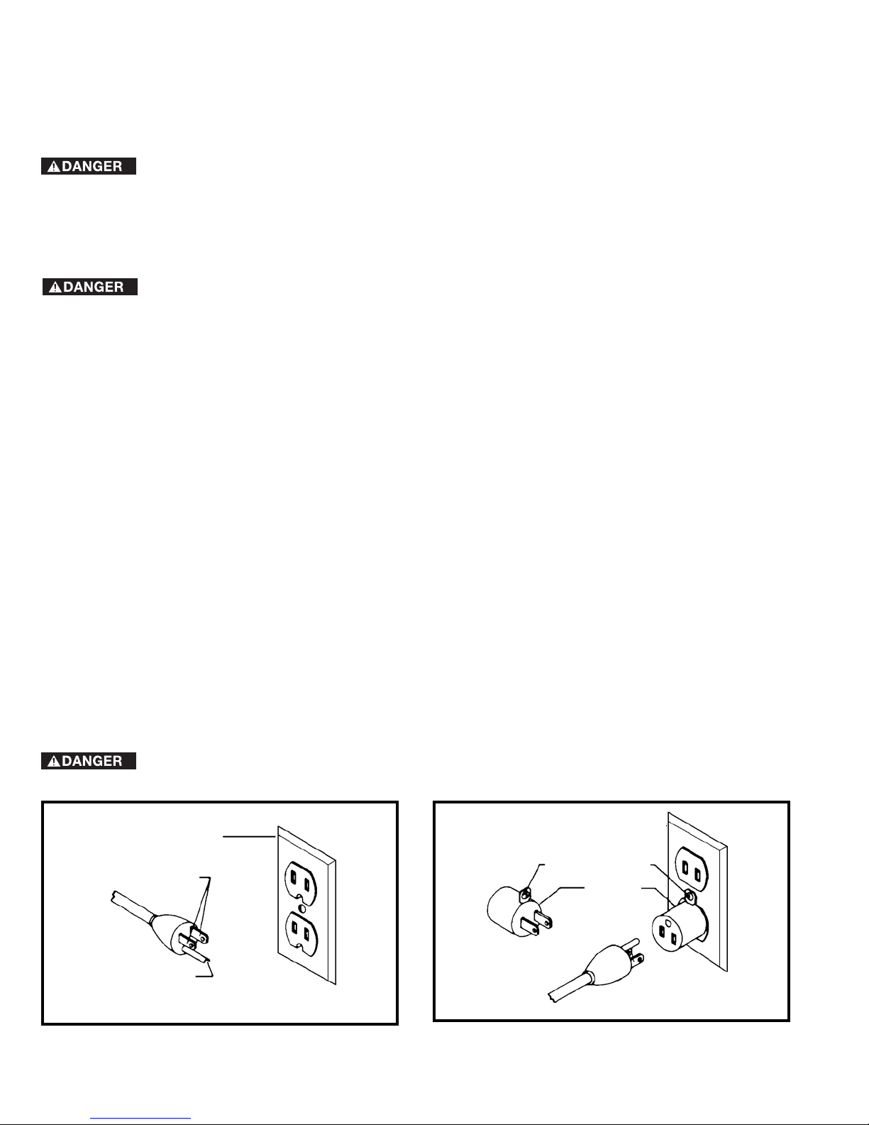
Use only 3-wire extension cords that have 3-prong grounding type plugs and matching 3-conductor receptacles that
accept the machine’s plug, as shown in Fig. A.
Repair or replace damaged or worn cord immediately.
2. Grounded, cord-connected machines intended for use on a supply circuit having a nominal rating less than
150 volts:
If the machine is intended for use on a circuit that has an outlet that looks like the one illustrated in Fig. A, the
machine will have a grounding plug that looks like the plug illustrated in Fig. A. A temporary adapter, which looks like
the adapter illustrated in Fig. B, may be used to connect this plug to a matching 2-conductor receptacle as shown
in Fig. B if a properly grounded outlet is not available. The temporary adapter should be used only until a properly
grounded outlet can be installed by a qualified electrician. The green-colored rigid ear, lug, and the like, extending
from the adapter must be connected to a permanent ground such as a properly grounded outlet box. Whenever the
adapter is used, it must be held in place with a metal screw.
NOTE: In Canada, the use of a temporary adapter is not permitted by the Canadian Electric Code.
In all cases, make certain that the receptacle in question is properly grounded. If you are not sure,
have a qualified electrician check the receptacle.
GROUNDED OUTLET BOX
CURRENT
CARRYING
PRONGS
GROUNDING BLADE
IS LONGEST OF THE 3 BLADES
Fig. A
GROUNDING MEANS
ADAPTER
Fig. B
6
Page 7
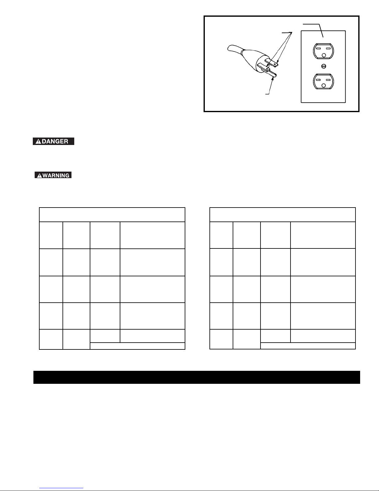
3. 240 VOLT SINGLE PHASE OPERATION
The motor supplied with your machine is a dual voltage,
120/240 volt motor. It is shipped ready-to-run for 120
volt operation. However, it can be converted for 240 volt
operation.
A qualified electrician should do the conversion, or the
machine can be taken to an Authorized DELTA Service
Center. When completed, the machine must conform to the
National Electric Code and all local codes and ordinances.
The machine is converted by re-wiring the motor for 240
volts, installing a 240 volt plug on the power supply cord
and replacing the switch with one that is rated for 240 volt
operation.
GROUNDED OUTLET BOX
CURRENT
CARRYING
PRONGS
GROUNDING BLADE
IS LONGEST OF THE 3 BLADES
Be sure the 240 volt plug is only used in an outlet having the same
configuration as the plug illustrated in Fig. C. No adapter should
be used with the 240 volt plug.
In all cases, make certain that the receptacle in question is properly grounded. If you are not sure, have a
qualified electrician check the receptacle.
Fig. C
EXTENSION CORDS
which has a 3-prong grounding type plug and matching receptacle which will accept the machine’s plug. When using an extension
cord, be sure to use one heavy enough to carry the current of the machine. An undersized cord will cause a drop in line voltage,
resulting in loss of power and overheating. Fig. D-1 or D-2, shows the correct gauge to use depending on the cord length. If in doubt,
use the next heavier gauge. The smaller the gauge number, the heavier the cord.
MINIMUM GAUGE EXTENSION CORD
RECOMMENDED SIZES FOR USE WITH STATIONARY ELECTRIC MACHINES
Ampere
rating Volts
0-6 120
0-6 120 25-50 16 AWG
0-6 120 50-100 16 AWG
0-6 120 100-150 14 AWG
6-10 120
6-10 120 25-50 16 AWG
6-10 120 50-100 14 AWG
6-10 120 100-150 12 AWG
10-12 120
10-12 120 25-50 16 AWG
10-12 120 50-100 14 AWG
10-12 120 100-150 12 AWG
12-16 120
12-16 120 25-50 12 AWG
12-16 120
Use proper extension cords. Make sure your extension cord is in good condition and is a 3-wire extension cord
MINIMUM GAUGE EXTENSION CORD
RECOMMENDED SIZES FOR USE WITH STATIONARY ELECTRIC MACHINES
Total
length of
cord in
feet
up to
25 18 AWG
up to
25 18 AWG
up to
25 16 AWG
up to
25 14 AWG
GREATER THAN 50 FEET NOT RECOMMENDED
Gauge of
extension cord
Fig. D-1
Ampere
rating Volts
0-6 240
0-6 240 50-100 16 AWG
0-6 240 100-200 16 AWG
0-6 240 200-300 14 AWG
6-10 240
6-10 240 50-100 16 AWG
6-10 240 100-200 14 AWG
6-10 240 200-300 12 AWG
10-12 240
10-12 240 50-100 16 AWG
10-12 240 100-200 14 AWG
10-12 240 200-300 12 AWG
12-16 240
12-16 240 50-100 12 AWG
12-16 240
Total
length of
cord in
feet
up to
50 18 AWG
up to
50 18 AWG
up to
50 16 AWG
up to
50 14 AWG
GREATER THAN 50 FEET NOT RECOMMENDED
Gauge of
extension cord
Fig. D-2
FUNCTIONAL DESCRIPTION
FOREWORD
DELTA Model 17-959L is a 17" floor model drill press. This heavy-duty machine has a 3/4 HP, 120/240V induction motor,
5/8" capacity chuck and key, cast iron table, rack and pinion elevation mechanism, and external depth stop. The 17-959L
has a tilting table for angle drilling. Side edges and parallel slots are provided for fast workpiece clamping.
NOTICE: The photo on the manual cover illustrates the current production model. All other illustrations contained in
the manual are representative only and may not depict the actual color, labeling, or accessories, and are intended to
illustrate technique only.
7
Page 8
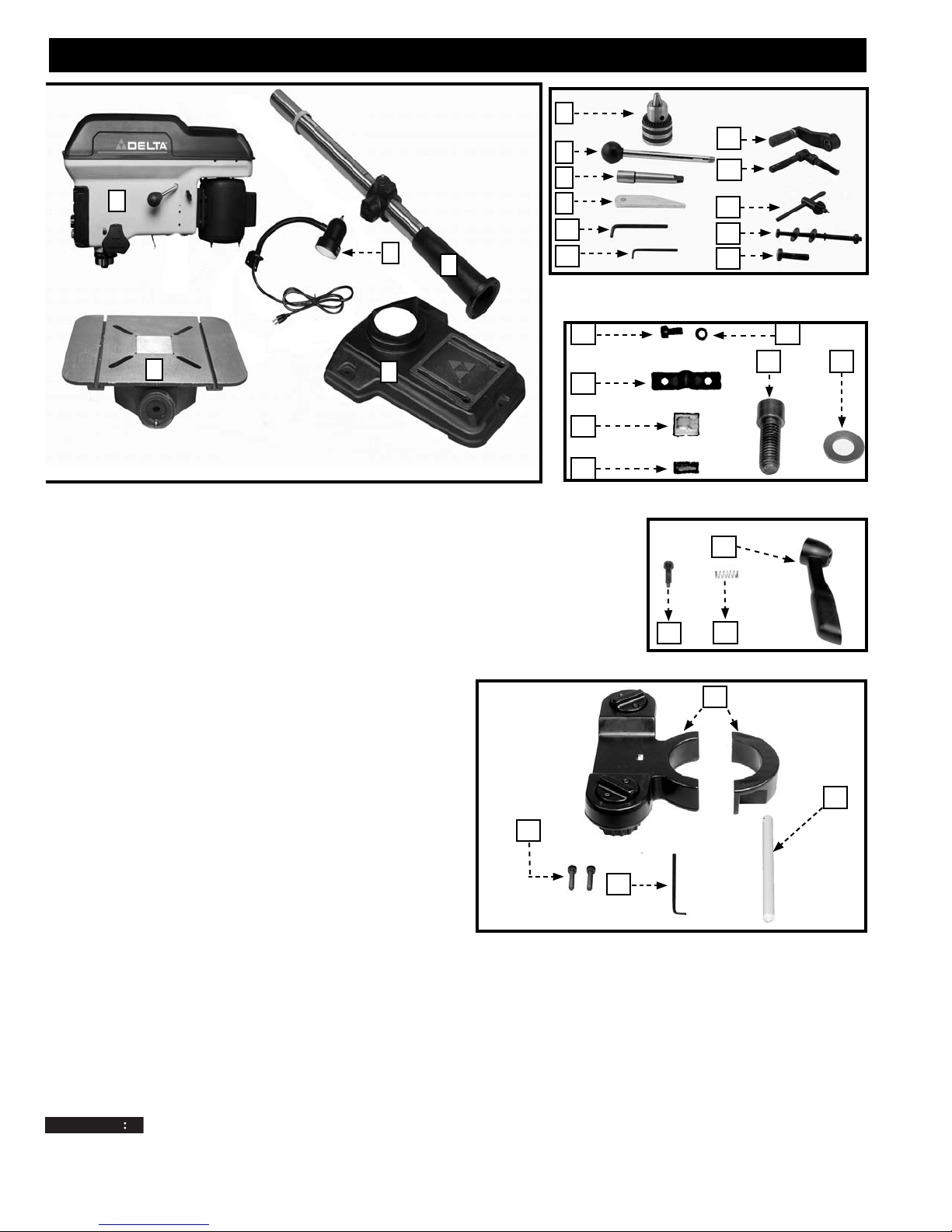
CARTON CONTENTS
6
7
8
1
4
3
9
10
11
12
13
14
15
16
2
1. Drill Press Head
2. Table
3. Table Bracket and Column
4. Light
5. Base
6. Chuck
7. Handle (3)
8. Spindle Adapter
9. Drift Key
10. 5mm Hex Wrench
11. 3mm Hex Wrench
12. Table Raising and Lowering Handle
13. Table Clamp Handle
14. Chuck Key
15. (3) M8 x 1.25 x 125mm carriage head screws,
(4) flat washers, (2) lockwashers, and (2) hex nuts
(for fastening drill press to a supporting surface)
16. M10 x 1.5 x 40mm Hex Head Screws (4)
17. M6 x 1 x 12mm Hex Cap Head Screw (2)
18. 1/4" Washer
19. Cord Strain Relief
20. Cord Clamp (2)
21. Cord Bushing
22. 12mm Hex Head Bolt
23. Flat Washer
24. Screws (2)
25. Springs (2)
26. Forward tilt levers
27. Laser
28. Laser Alignment Rod
29. 4mm Hex Wrench
30. Hex Head Cap Screws (2)
31. 12mm Hex Wrench (Not Shown)
5
30
17
19
20
21
29
24
18
22 23
26
25
27
28
UNPACKING AND CLEANING
Carefully unpack the machine and all loose items from the shipping container(s). Remove the rust-preventative oil from
unpainted surfaces using a soft cloth moistened with mineral spirits, paint thinner or denatured alcohol.
NOTICE
thinner for cleaning your machine. Such materials can easily catch fire. After cleaning, cover the unpainted surfaces
with a good quality household floor paste wax.
FIRE HAZARD. Do not use highly volatile solvents such as gasoline, naphtha, acetone or lacquer
8
Page 9
ASSEMBLY
RISK OF UNSAFE OPERATION. For your own safety, do not connect the machine to the power source
until the machine is completely assembled and you read and understand the entire instruction manual.
ASSEMBLY TOOLS REQUIRED
3mm and 5mm hex wrench (supplied)
10mm, 17mm, 24mm open end or socket wrenches (not supplied)
ASSEMBLY TIME ESTIMATE
Assembly for this machine takes approximately 30 minutes to 1 hour.
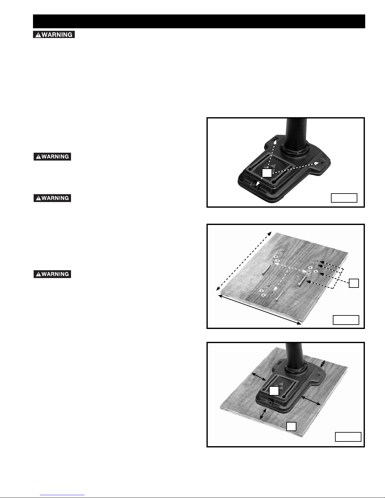
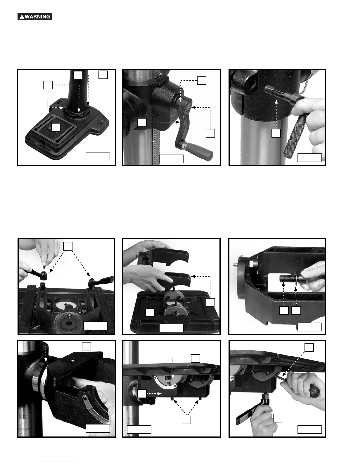
1. If you plan to use your drill press in a permanent
location, you must secure the drill press base to the
supporting surface with fasteners through the three
mounting holes (A) Fig. 1 in the drill press base.
RISK OF UNSAFE OPERATION. If you
do not fasten your drill press in a permanent manner,
you must fasten the drill press to a plywood mounting
board to prevent the drill press from tipping over
during normal use.
A
RISK OF UNSAFE OPERATION. Use
a good grade of plywood with a minimum 3/4"
thickness. Do not make the mounting board from
particle board since particle board breaks easily.
2. Use a plywood board base with the minimum
dimensions as shown in Fig. 2 for mounting the drill
press base to a supporting surface.
3. Place the drill press base (D) Fig. 3 centered on the
supporting surface (E).
RISK OF UNSAFE OPERATION. Make
sure that the plywood extends a minimum of 3" on all
four sides of the base as shown in Fig. 3.
4. Drill three 3/8" diameter holes through the holes (A)
Fig. 1 in the drill press base, and in the supporting
surface (E) Fig. 3.
NOTE: Place a piece of scrap wood underneath the
supporting surface when drilling the through holes so
that the drill bit will not damage the material beneath
the supporting surface.
5. Fasten the drill press base to the mounting board
using the carriage bolts, flat washers, lockwashers,
and hex nuts (C) Fig. 2 furnished with your drill
press. Countersink the holes for the carriage bolt
heads and flat washers under the board so that
the bolt heads are flush with or below the bottom
surface of the board. Use a flat washer, lock washer,
and hex nut above the drill press base.
28"
MINIMUM
21" MINIMUM
3" MINIMUM
3" MINIMUM
Fig. 1
C
Fig. 2
3" MINIMUM
D
3" MINIMUM
E
Fig. 3
9
Page 10
RISK OF UNSAFE OPERATION. You must secure the plywood base to the floor or supporting
surface if the drill press has any tendency to vibrate, slide, or walk during normal operation.
6. Attach the column (A) Fig. 4 to the base (B) using the four M10 x 40mm hex head screws (C), three of which are
shown.
7. Attach the table adjusting handle (D) Fig. 5 to the worm gear shaft (E). Tighten the screw (F) against the flat on the
shaft with the 3mm wrench supplied.
8. Thread the table clamp handle (G) Fig. 6 in the hole in rear of table bracket.
A
C
C
F
D
B
Fig. 4
E
Fig. 5
G
Fig. 6
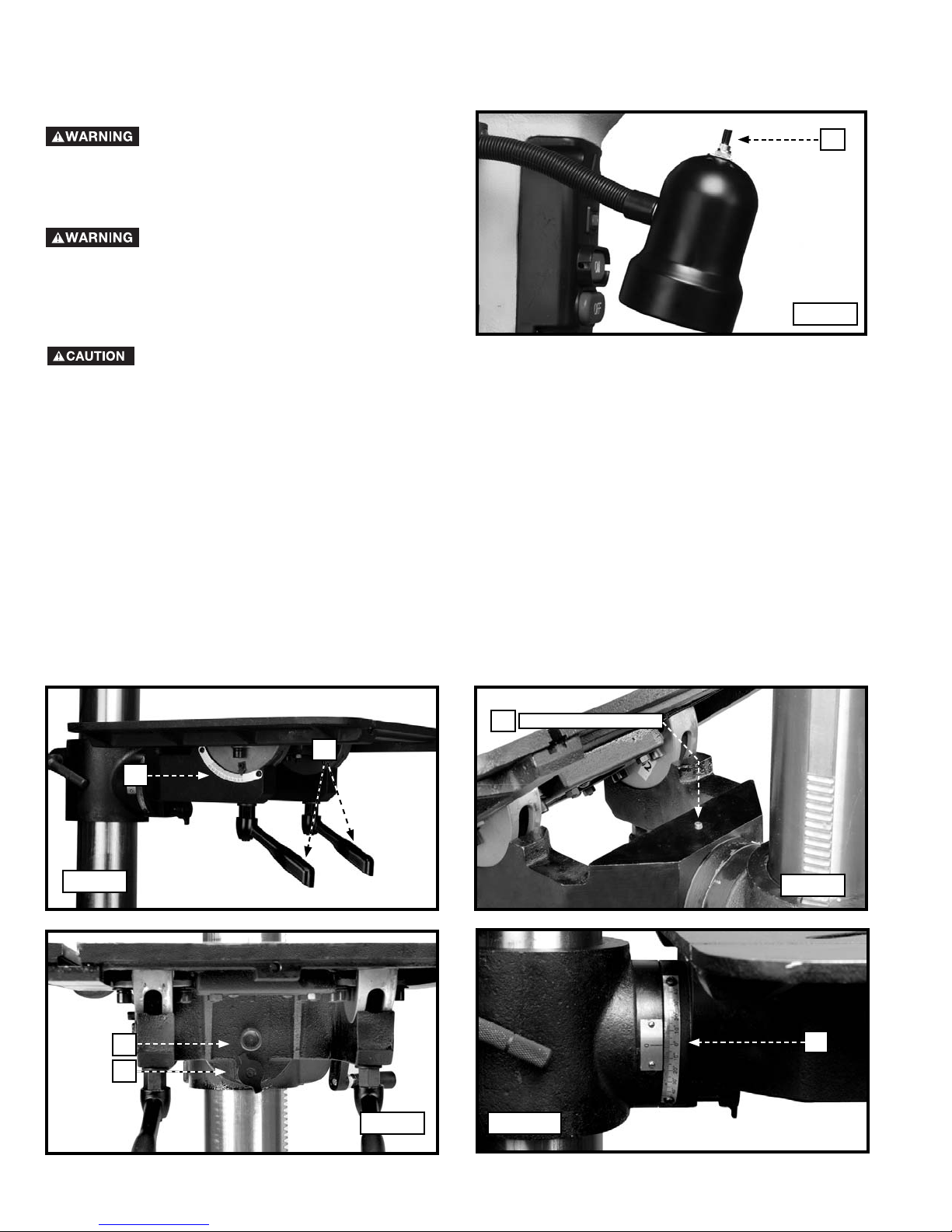
9. Attach the levers to the underside of the table by turning the screw in the lever clockwise (Fig. 7).
10. Remove both entire lever assemblies (A) Fig. 7 by turning them counter-clockwise. Remove the washers.
11. Lift the table support (B) Fig. 8 from the table (C).
12. Place the flat washer (D) Fig. 9 with the raised side against the 12mm bolt (E).
13. Insert the bolt into the table support, then into the hole in the knuckle (G) Fig. 10. Tighten securely.
14. Align the bolts (H) in the trunnion (J) with the holes in the table support (K).
15. Replace the washers and lever assemblies that were removed in STEP 10. Tighten securely.
NOTE: The bolts in the trunnion are moveable. To make the replacing of the levers easier, insert a athead screwdriver
(L) Fig. 12 in the opening of the trunnion against the bolts to steady them.
A
B
D
E
Fig. 9
L
Fig. 7
G
C
Fig. 8
J
K
Fig. 10
Fig. 11
10
H
G
Fig. 12
Page 11
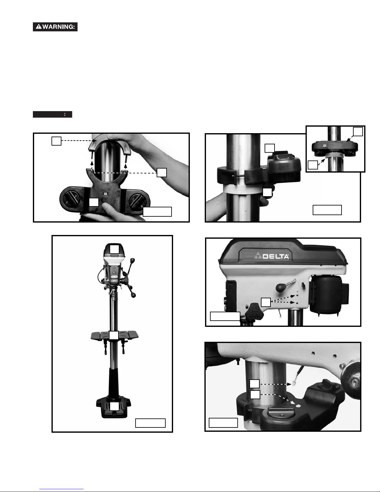
ATTACHING THE LASER AND HEADSTOCK TO THE COLUMN
EYE INJURY – LASER LIGHT. Do not stare into the laser beam or aperture or into a reflection
from a mirror-like surface.
1. Use the two socket head cap screws (C) Fig. 13 included in laser packaging and the supplied 4mm hex wrench to
attach the front laser housing (A) Fig. 13 to the rear laser housing (B) loosely.
2. Place this laser housing assembly on the drill press column (D) Fig. 14. Rest it on the collar (E) Fig. 14.
3. Place the drill press head (K) Fig. 15A on the column as far as it will go. Align the head (K) Fig. 15A with the table
(L) and the base (M). Tighten the two head-locking screws (N) Fig. 15B with the 5mm wrench supplied.
4. Slide the laser up on the column until you can plug the power wire (F) Fig. 16 into the socket of the laser (G)
Fig. 16.
5. Slide the laser up flush against the headstock.
6. Tighten the screws on the laser just enough to prevent movement.
NOTICE
B
Overtightening the laser screws can damage the laser.
C
A
Fig. 13
K
D
D
E
E
Fig. 14
L
M
Fig. 15A
N
Fig. 15B
F
G
Fig. 16
11
Page 12
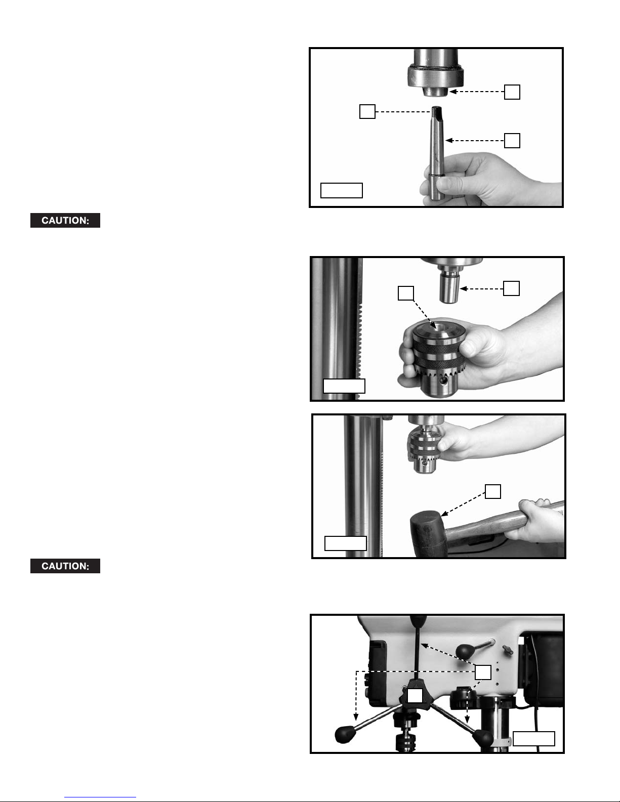
INSTALLING THE CHUCK
IMPORTANT: Make certain that the tapered hole in the
bottom of the spindle (T) Fig. 17, and the taper on the
spindle adapter (U) are clean and free of grease, lacquer,
or rust-preventive coatings.
NOTE: Household oven cleaner can effectively remove
these coatings from the spindle and spindle adapter.
However, carefully follow the manufacturer’s safety rules
regarding its use.
Push the spindle adapter (U) Fig. 17 into the spindle (T).
making certain that the tang (V) engages the mating slot
inside the spindle (T).
RISK OF PROPERTY DAMAGE. To avoid damage to the laser, prevent the cleaning solution from
coming in contact with the laser pod. You can clean the laser pod with a dry cotton cloth.
IMPORTANT: Make certain the spindle taper (O) Fig. 18,
and tapered hole in chuck (P) are clean and free of any
grease, lacquer, or rust preventive coatings.
NOTE: Household oven cleaner can effectively remove
any substance from the chuck. However, carefully follow
the manufacturer's safety rules concerning its use.
Fig. 17
V
P
T
U
O
IMPORTANT: Open the chuck jaws as wide as possible,
making sure that the chuck jaws are inside the chuck.
Hold the chuck on the taper of the spindle. Tap it with
a soft-tip hammer (Q) Fig. 19 or a block of wood and
hammer to set the chuck.
RISK OF PROPERTY DAMAGE. To avoid damage to the chuck, NEVER drive the chuck on the
spindle with a metal hammer.
ATTACHING THE PINION SHAFT HANDLES
Fig. 18
Q
Fig. 19
Thread the three pinion shaft handles (R) in the three
holes located in the pinion shaft hub (S) Fig. 20.
R
S
Fig. 20
12
Page 13
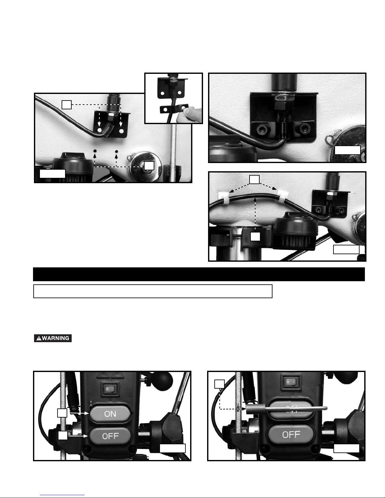
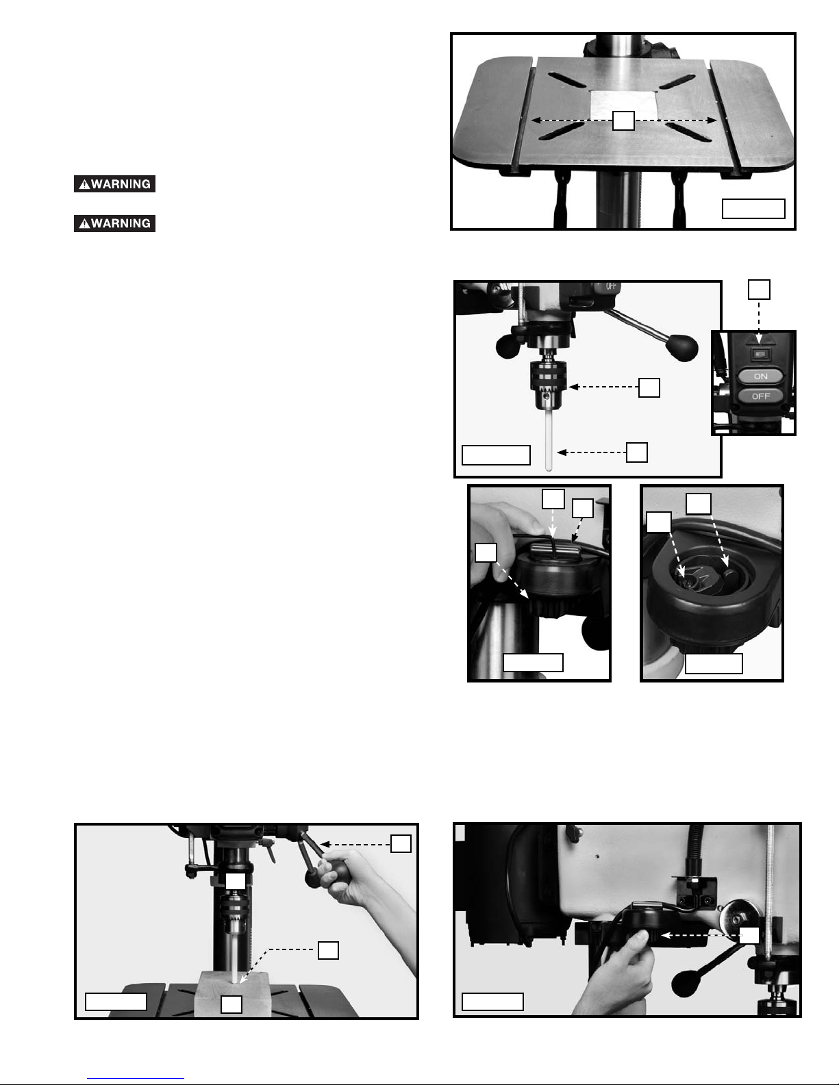
ATTACHING THE LAMP CORD BRACKET
1. Align the two holes in the lamp cord bracket (A) Fig. 21, with the two holes (B) on the side of the drill press head.
2. Place the cord bushing (inset) Fig. 21, around the top of the lamp cord.
3. Align the two holes in the lamp cord bracket with the two holes in the cord strain relief bracket and drill press head.
4. Place a 1/4" washer on an M6 x 1 x 12mm cap head screw. Insert the screw through the hole in the cord strain
relief bracket and the lamp cord bracket. Thread the screw into the drill press head (Fig. 22). Repeat this process
for the remaining hole in the cord strain relief bracket and tighten both screws securely.
A
Fig. 22
B
Fig. 21
H
5. Peel the backing from the cord clamps (H) Fig. 23,
and apply the clamps at the locations shown. Make
certain that the lamp cord is routed out of the way
of the drill, then secure the cord (J) to cord clamp (H)
Fig. 23.
J
Fig. 23
OPERATION
OPERATIONAL CONTROLS AND ADJUSTMENTS
STARTING AND STOPPING THE DRILL PRESS
1. The on/off switches (A and B) Fig. 24 are located on the front of the drill press. To turn the machine “ON”, depress the
“ON” switch.
2. To turn the machine “OFF”, depress the “OFF” switch.
Make sure that the switch is in the “OFF” position before plugging in the power cord. In the event of a
power failure, depress the “OFF” switch. An accidental start-up can cause injury.
IMPORTANT: When the machine is not in use, lock the switch in the “OFF” position to prevent unauthorized use, using a
padlock (A) Fig. 25 with a 3/16" diameter shackle.
A
A
B
Fig. 24 Fig. 25
13
Page 14
FLEXIBLE LAMP
The flexible lamp op er ates in de pen dent ly of the drill press. To turn the lamp “ON” and “OFF”, rotate switch (A) Fig. 26.
FIRE HAZARD. To reduce the risk of fire,
use a 40 watt or less, 120 volt, reflector track-type
light bulb (not supplied). DO NOT USE a standard
house hold light bulb. Do not allow the reflector tracktype light bulb to extend below the lamp shade.
RISK OF PERSONAL INJURY. Disconnect
the machine from the power source before making
any adjustments.
TABLE ADJUSTMENTS
RISK OF PERSONAL INJURY. Make sure that nothing is on the table and that the workpiece is clamped
down. Falling objects can cause an injury.
You can tilt the table forward from zero (0) to 45 degrees. To adjust:
1. Loosen the two forward tilt levers (A) Fig. 27.
2. Adjust the table to your desired angle. The scale (B) Fig. 27 is located on the side of the table support.
3. Tighten the levers (A) Fig. 27.
4. A positive stop (C) Fig. 28 is provided to return the table to the zero position. Adjust this stop by turning the screw/
stop (C), located under the table. Tighten the locknut to secure the stop.
You can tilt the table right or left. Positive stops are included for 0, 45 and 90 degrees. To adjust:
1. Loosen the table bolt (E) Fig. 29 approximately 1/4 turn with the supplied 12mm hex wrench.
2. Pull out the spring-loaded detent pin (F).
3. Rotate the table to your desired angle. The tilt scale (G) Fig. 30 is located on the knuckle behind the table. Use this
scale for accuracy. You can allow the detent pin to slide in to the positive stops (0, 45, and 90 degrees), but check
your scale to be sure of the exact angle.
4. Tighten the table bolt.
A
Fig. 26
Fig. 27
Located under table
C
A
B
Fig. 28
E
F
Fig. 29
Fig. 30
G
14
Page 15
T-SLOTS
The drill press table is fitted with two T-slots (L) Fig. 31
for use with various drill press accessories (stop blocks,
fences, or clamps). Use 5/16" T-bolts when attaching
your accessory to the table.
ADJUSTING THE LASERS
Disconnect the machine from the
power source.
LASER LIGHT. Do not stare into the
beam, aperture, or into a reflection from a mirror-like
surface.
L
Fig. 31
MAKING THE LASERS PARALLEL
1. Install the alignment pin (A) Fig. 32 in the chuck (B).
Make sure that the pointed end of the alignment pin
is down. The black scribed line on the pin should
face toward the left laser.
2. Turn on the lasers using the switch (C-inset) Fig. 32
on the front of the headstock.
3. With the supplied hex wrench, remove the two
screws (F) Fig. 33 and the cap (G) above the left side
of the laser housing.
4. Loosen the laser retainer screw (H) Fig. 34.
5. Move the laser lever (I) Fig. 34 so that the laser is
shining on the alignment pin. Adjust the lever (I) until
the laser is parallel with the black line.
NOTE: You may have to move the laser holder (J) Fig. 33
in order to shine the laser on the alignment pin. Adjust
the laser with the lever (I).
6. Tighten the laser retainer screw (H) Fig. 34. Replace
the cap (G) Fig. 33 and loosely tighten the two
screws (F).
7. Repeat for the other side.
MAKING THE LASERS INTERSECT
Fig. 32
J
Fig.33
C
B
A
F
G
H
I
Fig. 34
1. Place a piece of wood (A) Fig. 35 on the table and clamp it in place.
2. Use the handle (B) to lower the quill (C). Make an indentation in the wood with the alignment pin (D) Fig. 35.
3. Turn on the laser and adjust both beams to intersect at that point by rotating the laser holder (A) Fig. 36.
4. Ensure that the lasers align at different heights. Raise or lower the table, make a new indentation, and turn on the
lasers. If the lasers do not align at different heights, check the parallel adjustment.
5. Tighten the screws on each side of the laser housing, one of which is shown at (F) Fig. 33.
C
Fig. 35
A
B
A
D
Fig. 36
15
Page 16
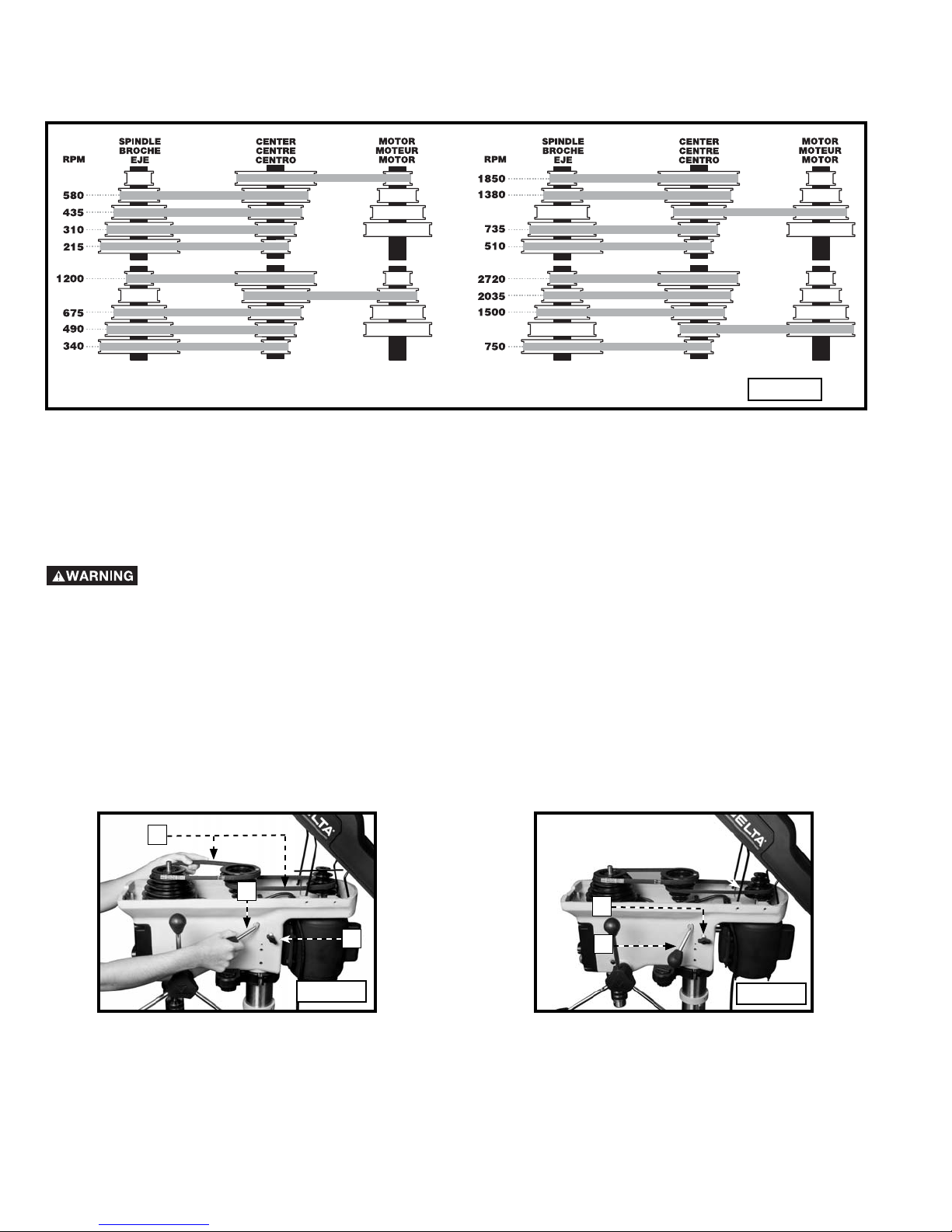
SPINDLE SPEEDS
Sixteen spindle speeds are available on the drill press. Fig. 37 illustrates the belt positions and the corresponding
speeds.
Fig. 37
CHANGING SPEEDS AND ADJUSTING BELT TENSION
NOTE: Sixteen spindle speeds are available on the drill press. A belt-positioning speed chart is located on the inside top
cover of the drill press.
DISCONNECT THE MACHINE FROM THE POWER SOURCE!
1. Open the top cover.
2. Loosen the lock-knob (A) Fig. 38 and the tension knob (located on the other side of the head casting). Move the tension
lever (B) forward.
3. Position both belts (C) Fig. 38 on the spindle pulley, center pulley, and motor pulleys according to the chart.
4. Move the tension lever (B) Fig. 39 to the rear to tension the belts.
NOTE: The belt should be just tight enough to prevent slipping. Excessive tension will reduce the life of the belt, pulleys, and
bearings. Tension is correct when you can flex the belt about 1" out of line, midway between the pulleys, using light finger
pressure.
5. Tighten the two tension lock knobs (A), one of which is shown.
C
B
A
A
B
Fig. 38
Fig. 39
16
Page 17
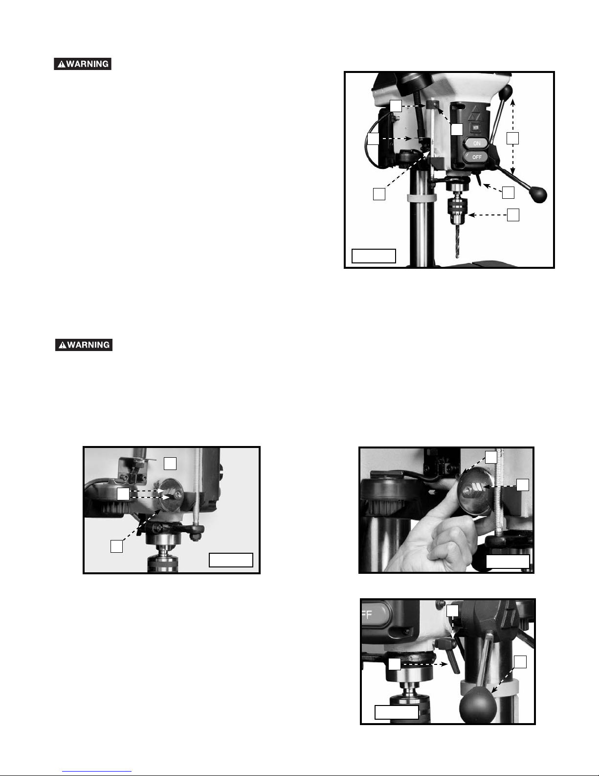
DRILLING HOLES TO DEPTH
When you want to drill a number of holes to the same depth, use the stop nut (A) Fig. 40 on the threaded stop rod (B).
DISCONNECT MACHINE FROM POWER SOURCE.
1. Insert the bit into the chuck.
2. Lower the chuck (G) Fig. 40, and the drill bit to your
chosen depth by rotating the pinion shaft handles (C).
Lock the quill in position by tightening the quill locking
lever (D).
NOTE: The quill locking lever (D) is spring-loaded. Change
it by pulling out on the handle and repositioning the hub of
the handle on the nut located underneath the hub.
3. Depress the spring-loaded button (E) Fig. 40 and move
the stop nut (A) until the bottom of the nut contacts the
stop (F). Loosen the quill locking-lever (D) to allow the
chuck and drill bit to return to the up position.
4. Connect the machine to the power source and drill
a test hole to check the adjustment. Readjust, if
necessary, by rotating the stop nut (A) Fig. 40 for fine
adjustment. You do not have to depress the button (E)
to rotate the stop nut (A).
Fig. 40
A
E
F
B
C
D
G
ADJUSTING THE SPINDLE RETURN SPRING
The spindle will automatically return slowly to its upper position when the handle is released. However, to adjust, if necessary:
DISCONNECT THE MACHINE FROM THE POWER SOURCE!
1. Loosen the nuts (B) Fig. 41, but do not remove. Make sure that the spring housing (A) remains engaged with head casting (C).
2. While firmly holding the spring housing (Fig. 42), pull out the housing and rotate it (counter-clockwise to increase or
clockwise to decrease) until the boss (D) is engaged with the next notch on the housing. Tighten the two nuts (B)
Fig. 41 to hold the housing in place.
IMPORTANT: The inside nut (E) Fig. 42 should not contact the spring housing (A) Fig. 41.
C
D
E
B
A
Fig. 41
Fig. 42
C
R
AISING AND LOWERING THE SPINDLE
Raise and lower the spindle with the pinion handles (A)
Fig. 43. You can lock the quill at any point in its travel by
tightening locking lever (B).
B
A
NOTE: The quill locking lever (B) is spring-loaded. Pull
outward on handle and reposition it on its hub (C).
Fig. 43
17
Page 18
MACHINE USE
NOTE: Use drill bits with shank diameters of 5/8" or less.
NOTE: After installing a drill bit, use the supplied key to tighten all three locations on the chuck.
The use of accessories and attachments not recommended by DELTA may result in risk of injury.
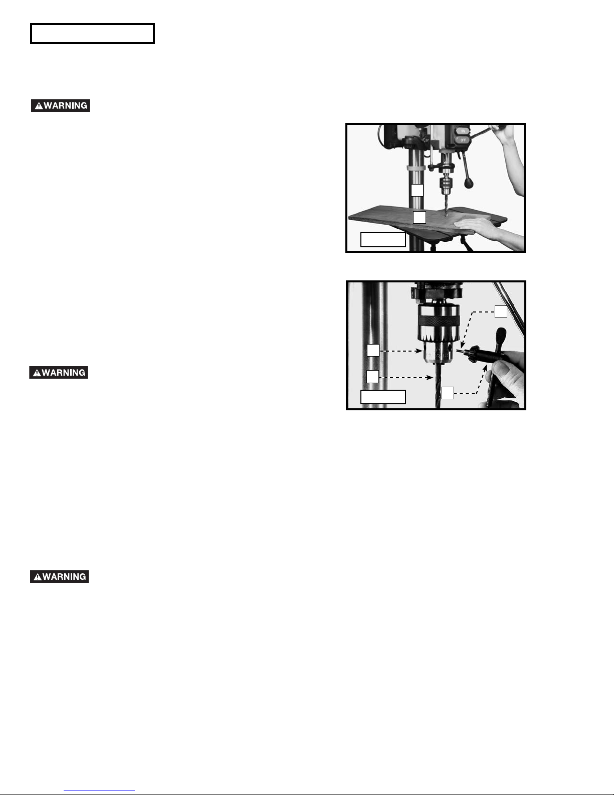
IMPORTANT: When the workpiece (A) Fig. 44 is long
enough, position it on the table with one end against the
left side of the column (B) to prevent the workpiece from
rotating. If it is not possible to support the workpiece
against the column, clamp the workpiece to the table.
Fig. 44
B
A
INSTALLING AND REMOVING DRILL BITS
NOTE: Use drill bits with a shank of 5/8" or less in diameter.
D
B
DISCONNECT THE MACHINE FROM THE
POWER SOURCE!
1. Insert the smooth end of drill bit (A) Fig. 45 in the chuck (B) as far as it will go, and then back the bit out 1/16" (or
up to the flutes for small bits).
2. Center the drill bit (A) Fig. 45 in the chuck (B) before tightening the chuck with the key (C).
3. Turn the chuck key (C) Fig. 45 clockwise to tighten and counter-clockwise to loosen the chuck jaws.
4. Tighten all three chuck jaws to secure the drill bit sufficiently to prevent slipping.
5. Remove the chuck key (C) Fig. 45 from the chuck before starting the drill press. The chuck key (C) is equipped with
a self-ejecting pin (D) which helps minimize the potential for the key to be left in the chuck.
A
Fig. 45
C
CORRECT DRILLING SPEEDS
Factors that determine the correct speed are 1) the workpiece, 2) the size of the hole, 3) the type of bit or other cutter,
and 4) the quality of cut.
Use the recommended speed for the the drill press bit and workpiece.
DRILLING WOOD
Twist drills, usually intended for metal drilling, can also be used for boring holes in wood. However, machine spur bits
are generally preferred for working in wood. These bits cut a flat-bottom hole and are designed for removal of wood
chips. Do not use hand bits (screw tip). At drill press speeds, they lift and rotate the workpiece.
For through boring, align the workpiece so that the bit will go through the center hole in the table. Scribe a vertical line
on the front of the column and a matching mark on the table bracket and the drill press head, so that the table and
drill press head can be clamped in the center position at any height.
Feed the workpiece slowly when the bit is close to cutting through the wood to prevent splintering the bottom face.
Use a scrap piece of wood as a base block under the work to reduce splintering and to protect the point of the bit.
18
Page 19

DRILLING METAL
Use clamps to hold metal workpieces. Never hold the workpiece in your bare hand. The drill bit can seize the work at
any time, especially when breaking through the workpiece and cause damage to the machine or injury to you. The drill
bit will break if the workpiece strikes the column.
Clamp the workpiece firmly. Any tilting, twisting, or shifting results not only in a rough hole, but also in bit breakage.
For flat work, lay the workpiece on a wooden base and clamp it firmly against the table to prevent it from turning. If
the workpiece is of irregular shape and cannot lay flat on the table, securely block or clamp it.
TROUBLESHOOTING
For assistance with your machine, visit our website at www.deltamachinery.com for a list of service centers or call the
DELTA Machinery help line at 1-800-223-7278 (In Canada call 1-800-463-3582).
MAINTENANCE
KEEP MACHINE CLEAN
Periodically blow out all air passages with dry compressed air. All plastic parts should be cleaned with a soft damp
cloth. NEVER use solvents to clean plastic parts. They could possibly dissolve or otherwise damage the material.
Wear certified safety equipment for eye, hearing and respiratory protection while using compressed air.
FAILURE TO START
Should your machine fail to start, check to make sure the prongs on the cord plug are making good contact in the
outlet. Also, check for blown fuses or open circuit breakers in the line.
LUBRICATION & RUST PROTECTION
Apply household floor paste wax to the machine table, extension table or other work surface weekly. Or use a
commercially available protective product designed for this purpose. Follow the manufacturer’s instructions for use
and safety.
To clean cast iron tables of rust, you will need the following materials: a sheet of medium Scotch-Brite™ Blending Hand
Pad, a can of WD-40® and a can of degreaser. Apply the WD-40® and polish the table surface with the Scotch-Brite
pad. Degrease the table, then apply the protective product as described above.
SERVICE
REPLACEMENT PARTS
Use only identical replacement parts. For a parts list or to order parts, visit our website at
You can also order parts from your nearest factory-owned branch, or by calling our Customer Care Center at 1-800-223-7278
to receive personalized support from highly-trained technicians.
SERVICE AND REPAIRS
All quality tools will eventually require servicing and/or replacement of parts. For information about DELTA Machinery, its
factory-owned branches, or an Authorized Warranty Service Center, visit our website at www.deltamachinery.com or call
our Customer Care Center at 1-800-223-7278. All repairs made by our service centers are fully guaranteed against defective
material and workmanship. We cannot guarantee repairs made or attempted by others.
servicenet.deltamachinery.com.
You can also write to us for information at DELTA Machinery, 4825 Highway 45 North, Jackson, Tennessee 38305 - Attention:
Product Service. Be sure to include all of the information shown on the nameplate of your tool (model number, type, serial
number, etc.)
19
Page 20

FREE WARNING LABEL REPLACEMENT
If your warning labels become illegible or are missing, call
1-800-223-7278
for a free replacement.
ACCESSORIES
Since accessories other than those offered by DELTA have not been tested with this product,
use of such accessories could be hazardous. For safest operation, only DELTA recommended accessories
should be used with this product.
A complete line of accessories is available from your DELTA Supplier, Porter-Cable • DELTA Factory Service Centers,
and DELTA Authorized Service Stations. Please visit our website www.deltamachinery.com for a catalog or for the
name of your nearest supplier.
WARRANTY
To register your tool for warranty service visit our website at www.deltamachinery.com.
Two Year Limited New Product Warranty
DELTA will repair or replace, at its expense and at its option, any new DELTA machine, machine part, or machine accessory which in normal
use has proven to be defective in workmanship or material, provided that the customer returns the product prepaid to a DELTA factory
service center or authorized service station with proof of purchase of the product within two years and provides DELTA with reasonable
opportunity to verify the alleged defect by inspection. For all refurbished DELTA product, the warranty period is 180 days. DELTA may require
that electric motors be returned prepaid to a motor manufacturer’s authorized station for inspection and repair or replacement. DELTA will
not be responsible for any asserted defect which has resulted from normal wear, misuse, abuse or repair or alteration made or specifically
authorized by anyone other than an authorized DELTA service facility or representative. Under no circumstances will DELTA be liable for
incidental or consequential damages resulting from defective products. This warranty is DELTA’s sole warranty and sets forth the customer’s
exclusive remedy, with respect to defective products; all other warranties, express or implied, whether of merchantability, fitness for purpose,
or otherwise, are expressly disclaimed by DELTA.
LATIN AMERICA: This warranty does not apply to products sold in Latin America. For products sold in Latin America, see country specific
warranty information contained in the packaging, call the local company or see website for warranty information.
20
Page 21

LES INSTRUCTIONS IMPORTANTES DE SURETE
n’importe quel outil ou n’importe quel équipement. En utilisant les outils ou l’équipement, les précautions de sûreté
fondamentales toujours devraient être suivies pour réduire le risque de blessure personnelle. L’opération déplacée,
l’entretien ou la modification d’outils ou d’équipement ont pour résultat la blessure sérieux et les dommages de
propriété. Il y a de certaines applications pour lequel outils et l’équipement sont conçus. La DELTA Machinery
recommande avec force que ce produit n’ait pas modifié et/ou utilisé pour l’application autrement que pour lequel il
a été conçu.
Si vous avez n’importe quelles questions relatives à son application n’utilisent pas le produit jusqu’à ce que vous avez écrit
Porter-Cable et nous vous avons conseillé.
(EN CANADA: 125 Mural St. Suite 300, Richmond Hill, ON, L4B 1M4)
Information en ce qui concerne l’opération sûre et correcte de cet outil est disponible des sources suivantes:
American National Standards Institute, 25 West 43rd Street, 4 floor, New York, NY 10036 www.ansi.org
ANSI 01.1 Safety Requirements for Woodworking Machines, and the U.S. Department of Labor regulations www.osha.gov
Lire et comprendre toutes instructions d’avertissements et opération avant d’utiliser
La forme en ligne de contact à www.deltamachinery.com
Courrier Postal: Technical Service Manager
DELTA Machinery
4825 Highway 45 North
Jackson, TN 38305
Power Tool Institute
1300 Sumner Avenue, Cleveland, OH 44115-2851
www.powertoolinstitute.org
National Safety Council
1121 Spring Lake Drive, Itasca, IL 60143-3201
CONSERVEZ CES INSTRUCTIONS!
MESURES DE SÉCURITÉ - DÉFINITIONS
Ce guide contient des renseignements importants que vous deviez bien saisir. Cette information porte sur
VOTRE SÉCURITÉ et sur LA PRÉVENTION DE PROBLÈMES D’ÉQUIPEMENT. Afin de vous aider à identifier
cette information, nous avons utilisé les symboles ci-dessous.
indique une situation dangereuse imminente qui, si elle n’est pas évitée, causera la mort ou des
blessures graves.
indique une situation potentiellement dangereuse qui, si elle n’est pas évitée, pourrait se solder par
un décès ou des blessures graves.
indique une situation potentiellement dangereuse qui, si elle n’est pas évitée pourrait se solder par
des blessures mineures ou modérées.
AVIS
n’est fait pour l’éviter, pourrait poser des risques de dommages matériels.
LA PROPOSITION DE CALIFORNIE 65
produire des poussières contenant des produits chimiques reconnus par l’État californien pour causer cancers,
malformations congénitales ou être nocifs au système reproducteur. Parmi ces produits chimiques, on retrouve:
• le plomb dans les peintures à base de plomb;
• la silice cristallisée dans les briques et le ciment ou autres articles de maçonnerie; et
• l’arsenic et le chrome dans le bois ayant subi un traitement chimique (ACC).
Le risque associé à de telles expositions varie selon la fréquence à laquelle on effectue ces travaux. Pour réduire toute
exposition à ces produits: travailler dans un endroit bien aéré, en utilisant du matériel de sécurité homologué tel un
masque antipoussières spécialement conçu pour filtrer les particules microscopiques.
indique une pratique ne posant aucun risque de dommages corporels mais qui par contre, si rien
Les scies, meules, ponceuses, perceuses ou autres outils de construction peuvent
21
Page 22

RÈGLES DE SÉCURITÉ GÉNÉRALES
l’inobservation de ces règles peut conduire à des blessures graves.
1. POUR SA SÉCURITÉ PERSONNELLE, LIRE LA NOTICE
D’UTILISATION, AVANT DE METTRE LA MACHINE EN
MARCHE, et pour aussi apprendre l’application et les limites de
la machine ainsi que les risques qui lui sont particuliers ainsi, les
possibilités d’accident et de blessures seront beaucoup réduites.
2. PORTEZ DES DISPOSITIFS DE PROTECTION DES YEUX
ET DE L’OUÏE. UTILISEZ TOUJOURS DES LUNETTES DE
SÉCURITÉ. Des lunettes ordinaires ne constituent PAS des
lunettes de sécurité. UTILISEZ DES ÉQUIPEMENTS DE SÛRETÉ
HOMOLOGUÉS. Les dispositifs de protection des yeux doivent
être conformes aux normes ANSI Z87.1. Les dispositifs de
protection de l’ouïe doivent être conformes aux normes ANSI
S3.19.
3. PORTER UNE TENUE APPROPRIÉE. Pas de cravates, de
gants, ni de vêtements amples. Enlever montre, bagues et autres
bijoux. Rouler les manches. Les vêtements ou les bijoux qui
se trouvent pris dans les pièces mobiles peuvent entraîner des
blessures.
4. NE PAS UTILISER LA MACHINE DANS UN
ENVIRONNEMENT DANGEREUX. L’utilisation d’outils
électriques dans des endroits humides ou sous la pluie peut
entraîner des décharges électriques ou une électrocution. Garder
la zone de travail bien éclairée pour éviter de trébucher ou
d’exposer les doigts, les mains ou les bras à une situation
dangereuse.
5. GARDER LES OUTILS ET LES MACHINES EN PARFAIT
ÉTAT. Garder les outils affûtés et propres afin d’obtenir le meilleur
et le plus sûr rendement. Suivre les instructions pour lubrifier
et changer les accessoires. Les outils et les machines mal
entretenus peuvent se dégrader davantage, et/ou entraîner des
blessures.
6. INSPECTER LES PIÈCES POUR DÉCELER TOUT
DOMMAGE. Avant d’utiliser la machine, la vérifier pour voir
s’il n’y a pas de pièces endommagées. Vérifier l’alignement
des pièces mobiles et si ces pièces ne se coincent pas, la
rupture de pièces, ou toute autre condition pouvant en affecter
le fonctionnement. Toute pièce ou protecteur endommagé doit
être réparé ou remplacé. Les pièces endommagées peuvent
dégrader davantage la machine et/ou entraîner des blessures.
7. GARDER L’AIRE DE TRAVAIL PROPRE. Les zones et établis
encombrés favorisent les accidents.
8. GARDER LES ENFANTS ET LES VISITEURS À DISTANCE.
L’atelier est un lieu potentiellement dangereux. Les enfants et les
visiteurs peuvent se blesser.
9. ÉVITER LE DÉMARRAGE ACCIDENTEL. S’assurer que
l’interrupteur est sur « OFF » (ARRÊT) avant de brancher le
cordon. En cas de coupure de courant, placer l’interrupteur
à la position « OFF » (ARRÊT). Un démarrage accidentel peut
entraîner des blessures.
10. UTILISER LES DISPOSITIFS PROTECTEURS. Vérifier que tous
les dispositifs protecteurs sont bien en place, bien fixés et en
bon état de marche pour éviter les blessures.
11. ENLEVER LES CLÉS DE RÉGLAGE ET CELLES DE
SERRAGE AVANT DE METTRE LA MACHINE EN MARCHE.
Les outils, les chutes et les autres débris peuvent être projetés
violemment et blesser.
12. UTILISER LA BONNE MACHINE. Ne pas forcer la machine ou
l’accessoire à faire un travail pour lequel il n’a pas été conçu.
Des dommages à la machine et/ou des blessures pourraient
s’ensuivre.
13. UTILISER LES ACCESSOIRES RECOMMANDÉS. L’utilisation
d’accessoires non recommandés par DELTA peut endommager
la machine et blesser l’utilisateur.
14. UTILISER LE CORDON PROLONGATEUR APPROPRIÉ.
S’assurer que le cordon prolongateur est en bon état. Lorsqu’un
cordon prolongateur est utilisé, s’assurer que celui-ci est d’un
calibre suffisant pour l’alimentation nécessaire à la machine. Un
cordon d’un calibre insuffisant entraînera une perte de tension
d’où une perte de puissance et surchauffe. Voir le tableau sur
les cordons prolongateurs pour obtenir le calibre approprié selon
la longueur du cordon et l’ampérage de la machine. S’il y a un
doute, utiliser un cordon d’un calibre supérieur. Plus le chiffre est
petit, plus le fil est gros.
15. FIXER LA PIÈCE.
l’objet si pratique. La perte de commande d’un objet peut
causer des dommages.
16. AVANCER LA PIÈCE DANS LE SENS CONTRAIRE À
LA ROTATION DE LA LAME, DE LA FRAISE OU DE LA
SURFACE ABRASIVE. L’alimentation dans l’autre sens peut
entraîner une projection violente de la pièce.
17. NE PAS FORCER LA MACHINE EN AVANÇANT LA PIÈCE
TROP VITE. Des dommages et/ou des blessures peuvent
s’ensuivre.
18. NE PAS SE PENCHER AU-DESSUS DE LA MACHINE. Une
perte de l’équilibre peut entraîner une chute sur la machine en
marche et causer des blessures.
19. NE JAMAIS MONTER SUR LA MACHINE. On peut se
blesser gravement si la machine bascule ou si l’on touche
accidentellement son outil tranchant.
20. NE JAMAIS LAISSER LA MACHINE EN MARCHE SANS
SURVEILLANCE. COUPER LE COURANT. Ne pas quitter la
machine tant qu’elle n’est pas complètement arrêtée. Un enfant
ou un visiteur pourrait se blesser.
21. METTRE LA MACHINE À L’ARRÊT « OFF » ET LA
DÉBRANCHER avant d’installer ou d’enlever des accessoires,
d’ajuster ou de changer des montages, ou lors des réparations.
Un démarrage accidentel peut entraîner des blessures.
22. METTRE L’ATELIER À L’ABRI DES ENFANTS AU MOYEN
DE CADENAS, D’INTERRUPTEURS PRINCIPAUX OU EN
ENLEVANT LES BOUTONS DES DISPOSITIFS DE MISE EN
MARCHE. Le démarrage accidentel de la machine par un enfant
ou un visiteur peut entraîner des blessures.
23. RESTER VIGILANT, ATTENTIF, ET FAIRE PREUVE DE BON
SENS. NE PAS UTILISER LA MACHINE LORSQUE L’ON EST
FATIGUÉ OU SOUS L’INFLUENCE DE DROGUES, D’ALCOOL
OU DE MÉDICAMENTS. Un instant d’inattention lors de
l’utilisation d’outils électriques peut entraîner des blessures
graves.
24.
PEUT PRODUIRE ET DISPERSER DE LA POUSSIÈRE OU
D’AUTRES PARTICULES EN SUSPENSION DANS L’AIR,
TELLES QUE LA SCIURE DE BOIS, LA POUSSIÈRE DE
SILICIUM CRISTALLIN ET LA POUSSIÈRE D’AMIANTE.
Dirigez les particules loin du visage et du corps. Faites
toujours fonctionner l’outil dans un espace bien ventilé et
prévoyez l’évacuation de la poussière. Utilisez un système
de dépoussiérage chaque fois que possible. L’exposition à
la poussière peut causer des problèmes de santé graves et
permanents, respiratoires ou autres, tels que la silicose (une
maladie pulmonaire grave) et le cancer, et même le décès de
la personne affectée. Évitez de respirer de la poussière et de
rester en contact prolongé avec celle-ci. En laissant la poussière
pénétrer dans vos yeux ou votre bouche, ou en la laissant
reposer sur votre peau, vous risquez de promouvoir l’absorption
de substances toxiques. Portez toujours des dispositifs de
protection respiratoire homologués par NIOSH/OSHA,
appropriés à l’exposition à la poussière et de taille appropriée, et
lavez à l'eau et au savon les surfaces de votre corps qui ont été
exposées.
Utilisez les brides ou un étau pour tenir
L’UTILISATION DE CET OUTIL
22
Page 23

RÈGLES SPÉCIFIQUES ADDITIONNELLES DE SÛRETÉ
l’inobservation de ces règles peut conduire à des blessures graves.
1. NE PAS FAIRE FONCTIONNER CETTE MACHINE
AVANT QU’ELLE NE SOIT ENTIÈREMENT ASSEMBLÉE
ET INSTALLÉE CONFORMÉMENT À CES DIRECTIVES.
Une machine mal assemblée peut provoquer des blessures
graves.
2. DEMANDER CONSEIL à un superviseur, instructeur, ou
toute autre personne qualifiée si vous ne maîtrisez pas
parfaitement l’utilisation de cette machine. La connaissance
est synonyme de sécurité.
3. SUIVRE TOUS LES CODES DE CÂBLAGE et les
connexions électriques recommandées afin d’éviter tout
choc électrique ou électrocution.
4. FIXER LA MACHINE SUR UNE SURFACE DE SUPPORT.
Les vibrations sont susceptibles de faire glisser, « marcher »,
ou basculer la machine.
5. NE JAMAIS DÉMARRER LA MACHINE AVANT DE
RETIRER DE LA TABLE TOUT OBJET (outils, morceaux de
déchet de découpe, etc.). Les débris peuvent être projetés à
grande vitesse.
6. NE JAMAIS DÉMARRER LA MACHINE avec une mèche,
un outil de coupe ou un cylindre de contact contre l’ouvrage.
La perte de contrôle de l’ouvrage peut provoquer de graves
blessures.
7. VERROUILLER CORRECTEMENT LA MÈCHE, L’OUTIL
DE COUPE OU LE CYLINDRE DE CONTACT DANS LE
MANDRIN avant d’utiliser cette machine.
8. RETIRER LA CLÉ DU MANDRIN AVANT DE DÉMARRER
LA MACHINE. La clé du mandrin risque d’être projetée à
grande vitesse.
9. SERRER TOUTES LES POIGNÉES DE VERROUILLAGE
avant de démarrer la machine. La perte de contrôle de
l’ouvrage peut provoquer de graves blessures.
10. UTILISER SEULEMENT DES MÈCHES, OUTILS
DE COUPE, CYLINDRES DE CONTACT OU AUTRES
ACCESSOIRES avec une queue à la dimension
recommandée dans le mode d’emploi. Un accessoire
de la mauvaise taille peut endommager la machine et/ou
provoquer de graves blessures.
11. UTILISER SEULEMENTS DES MÈCHES, OUTILS DE
COUPE OU CYLINDRES DE CONTACT intacts. Des articles
endommagés peuvent provoquer des défaillances qui
mèneraient à des blessures.
12. UTILISER LES VITESSES RECOMMANDÉES pour toutes
opérations.
D’autres vitesses peuvent provoquer des défaillances de la
machine qui endommageraient celle-ci et/ou provoqueraient
de graves blessures.
13. ÉVITER LES OPÉRATIONS MALADROITES ET ÉVITER
D’AVOIR LES MAINS MAL PLACÉES. En glissant
inopinément, votre main pourrait percuter la mèche.
14. TENIR LES BRAS, MAINS ET DOIGTS éloignés de la
mèche. De graves blessures à la main peuvent survenir.
15. TENIR FERMEMENT L’OUVRAGE CONTRE LA TABLE.
Ne pas percer un ouvrage si celui-ci ne repose pas sur un
côté plat contre la table ou s’il n’est pas fixé dans un étau.
Empêcher l’ouvrage de tourner en le rattachant à la table
ou en le fixant contre la colonne de la perceuse. La perte de
contrôle de l’ouvrage peut provoquer de graves blessures.
16. ÉTEINDRE LA MACHINE ET ATTENDRE QUE LA MÈCHE,
L’OUTIL DE COUPE OU LE CYLINDRE DE CONTACT
S’ARRÊTE COMPLÈTEMENT avant de nettoyer la zone
de travail, d’enlever des débris, de retirer ou de fixer un
ouvrage ou de changer l’angle de la table. Une mèche, un
outil de coupe ou un cylindre de contact en mouvement peut
provoquer de graves blessures.
17. SOUTENIR CORRECTEMENT LES OUVRAGES LONGS
OU LARGES. La perte de contrôle de l’ouvrage peut
provoquer de graves blessures.
18. NE JAMAIS EFFECTUER D’OPÉRATIONS DE TRAÇAGE,
D’ASSEMBLAGE, OU DE RÉGLAGE sur la table/l’espace
de travail lorsque la machine est en marche. De graves
blessures pourraient survenir.
19. ÉTEINDRE LA MACHINE, la débrancher, et nettoyer
la table/l’espace de travail avant de laisser la machine.
VERROUILLER L’INTERRUPTEUR EN POSITION D’ARRÊT
afin d’éviter toute utilisation non autorisée. Il se peut que
quelqu’un démarre accidentellement la machine et se blesse
gravement.
20. DES INFORMATIONS SUPPLÉMENTAIRES (i.e., une
vidéo sur la sécurité), indiquant comment utiliser des
outils électriques correctement et en toute sécurité, sont
disponibles auprès du Power Tool Institute, 1300 Sumner
Avenue, Cleveland, OH 44115-2851, États-Unis (www.
powertoolinstitute.com). Vous pouvez également vous
procurer des informations auprès du National Safety Council,
1121 Spring Lake Drive, Itasca, IL 60143-3201, États-Unis.
Veuillez vous reporter à la norme ANSI 01.01 de l’American
National Standards Institute concernant les machines de
travail du bois, ainsi que la réglementation OSHA 1910.213.
du département américain du travail.
RÈGLES ADDITIONNELLES DE SÛRETÉ POUR LE LASER
BLESSURE AUX YEUX – RAYONNEMENT LASER
Ne pas fixer du regard l’ouverture du faisceau ou le reflet du rayon sur une surface réfléchissante.
Ne pas utiliser d’outils optiques comme un télescope ou un théodolite pour regarder le faisceau laser.
BLESSURE AUX YEUX – RAYONNEMENT LASER
Ne pas utiliser le laser près des enfants et ne pas laisser les enfants utiliser le laser.
Ranger le laser inutilisé hors de la portée des enfants et des personnes sans expérience.
Arrêtez le laser en fin d’utilisation.
Ne pas démonter le module laser. Le rayonnement de classe II, produit par l’appareil, pourrait dépasser la limite si l’appareil est
démonté. Laser conforme aux normes 21 CFR 1040.10 et 1040.11.
L’utilisation de commandes ou de réglages ou l’exécution de procédures autres que celles précisées
dans la présente peut entraîner une exposition au rayonnement dangereux.
RISQUE D’EXPLOSION. Ne pas faire fonctionner le laser ou la perceuse de colonne dans un milieu
déflagrant, comme en présence de liquides, de gaz ou de poussières inflammables. Une étincelle pourrait enflammer les
poussières ou les vapeurs.
REMARQUE : Ne pas enlever ni altérer les étiquettes de mises en garde.
23
Page 24

RACCORDEMENTS ÉLECTRIQUES
Un circuit électrique séparé doit être utilisé pour les machines. Les fils de ce circuit doivent être au moins de calibre 12. Ce circuitdoit
être protégé par un fusible temporisé de 20 A. Si on utilise un cordon prolongateur, ce cordon doit être à trois fils, avoir unefiche à trois
broches et une prise de courant à trois cavités, mise à la terre qui correspond à la fiche de la machine. Avant debrancher la machine,
s’assurer que l’interrupteur se trouve en position « OFF » (ARRÊT) et que le courantélectrique présente les mêmes caractéristiques
que celles qui sont inscrites sur la machine. Toutes les connexions électriquesdoivent établir un bon contact. Le fonctionnement sur
une basse tension endommagera la machine.
Ne pas exposer la machine à la pluie, et ne pas l’utiliser dans des endroits humides.
SPÉCIFICATIONS DU MOTEUR
Cette machine est câblée pour un fonctionnement sur un courant alternatif de 120/240 volts, 60 Hz. Avant de brancher la machine,
s’assurer que l’interrupteur se trouve à la position « OFF » (ARRÊT).
INSTRUCTIONS DE MISE À LA TERRE
Cette machine doit être mise à la terre pendant son emploi, afin de protéger l’utilisateur des décharges
électriques.
1. Toutes les machines avec cordon mis à la terre: Dans l’éventualité d’un mauvais fonctionnement ou d’une panne, la mise à la
terre fournit un trajet de moindre résistance permettant de réduire le risque de décharge électrique. Cette machine est dotée d’un
cordon électrique possédant un conducteur de mise à la terre de l’équipement ainsi que d’une fiche mise à la terre. La fiche doit
être branchée dans une prise de courant correspondante, installée de façon adéquate et mise à la terre conformément à tous les
codes et règlements locaux.
Ne pas modifier la fiche fournie – si elle ne s’adapte pas à la prise de courant, il faut faire installer une prise de courant
convenable par un électricien compétent.
Un mauvais raccordement du conducteur de mise à la terre de l’équipement peut entraîner un risque de décharge électrique. Le
conducteur possédant un isolant avec surface extérieure de couleur verte, avec ou sans rayures jaunes, est le conducteur de
mise à la terre de l’équipement. Si une réparation ou un remplacement du cordon électrique s’avère nécessaire, ne pas brancher
le conducteur de mise à la terre de l’équipement à une borne sous tension.
Consulter un électricien compétent ou le personnel de service après-vente si on ne comprend pas entièrement les instructions de
mise à la terre, ou si l’on doute que la machines oit correctement mise à la terre.
Utiliser seulement des cordons prolongateurs à trois fils dotés d’une fiche mise à la terre, à trois broches, et de prises à trois
cavités convenant à la fiche de la machine, comme l’illustre la figure A.
Réparer ou remplacer sans délai tout cordon endommagé ou usé.
2. Machines avec cordon mis à la terre prévues pour une utilisation sur une alimentation nominale inférieure à 150 volts:
Si cette machine est prévue pour être utilisée sur un circuit qui comporte une prise semblable à celle illustrée à la figure A, la
machine devra comporter une fiche mise à la terre semblable à celle illustrée à la figure A. Un adaptateur temporaire semblable à
celui illustré à la figure B, peut être utilisé pour raccorder cette fiche à une prise à deux cavités comme celle illustrée à la figure B,
si une prise correctement mise à la terre n’est pas disponible. L’adaptateur temporaire ne doit être utilisé que jusqu’au moment
où une prise correctement mise à la terre est installée par un électricien compétent. L’oreille rigide ou autre dispositif semblable
de couleur verte, sur le dessus de l’adaptateur, doit être connecté sur une mise à la terre permanente comme, par exemple une
boîte à prises correctement mise à la terre. Quand un adaptateur est utilisé, celui-ci doit être retenu en place par une vis en métal.
REMARQUE: Au Canada, le Code canadien de l’électriciténe permet pas l’emploi d’un adaptateur temporaire.
électricien compétent de vérifier la prise.
Dans tous les cas, s’assurer quela prise en question est bien mise à la terre. Dans le doute, demander à un
BOÎTE À PRISES MISE À LA TERRE
BROCHES
CONDUCTRICES DE
COURANT
LA BROCHE DE MISE
À LA TERRE EST LA PLUS
LONGUE DES TROIS
Fig. A
OREILLE DE MISE À
LA TERRE
ADAPTATEUR
Fig. B
24
Page 25

3. FONCTIONNEMENT MONOPHASÉ À 240 VOLTS: Le
moteur fourni avec la machine est un moteur bitension de
120/240 volts. Il est livré, prêt à fonctionner, sous tension de
120 volts. Toutefois, il peut être converti au fonctionnement
sous 240 volts.
Un électricien professionnel devrait effectuer la conversion
ou utiliser les services d’un centre de réparations agréé
DELTA. Suite à la conversion, la machine doit être conforme
au Code électrique national et à tous les codes et à toutes les
ordonnances à l’échelle locale.
La conversion exige un recâblage du moteur pour 240 volts
grâce à l’installation d’une fiche de 240 volts sur le cordon
d’alimentation et le remplacement de l’interrupteur (le cas
échéant) avec un autre homologué pour un fonctionnement à
240 volts.
S’assurer que la fiche de 240 volts s’insère seulement dans une
prise ayant la même configuration que la fiche illustrée à la fig. C.
N’utiliser aucun adaptateur avec une fiche de 240 volts.
LA BOITE FONDE DE SORTIE
COURANT
PORTER
LA LAME FONDANT EST LA PLUS
LONGUE DES 3 LAMES
Fig. C
électricien compétentde vérifier la prise.
Dans tous les cas, s’assurer quela prise en question est bien mise à la terre. Dans le doute, demander à un
CORDON DE RALLONGE
état. En utilisant une corde de prolongation, soyez sûr d’employer un assez lourd pour porter le courant de la machine. Une corde
trop petite causera une baisse dans la tension secteur, ayant pour résultat la perte de puissance et de surchauffe. Fig. D-1 ou D-2,
expositions la mesure correcte à employer selon la longueur de corde. En cas de doute, utilisez la prochaine mesure plus lourde. Plus
le nombre de mesure est petit, plus la corde est lourde.
MESUR MINIMUM DE CORDE D’EXTENSION
TAILLES RECOMMANDÉES POUR L’USAGE AVEC STATIONNAIRES ÉLECTRIQUES LES OUTILS
Estimation
ampère Volts
0-6 120
0-6 120 25-50 16 AWG
0-6 120 50-100 16 AWG
0-6 120 100-150 14 AWG
6-10 120
6-10 120 25-50 16 AWG
6-10 120 50-100 14 AWG
6-10 120 100-150 12 AWG
10-12 120
10-12 120 25-50 16 AWG
10-12 120 50-100 14 AWG
10-12 120 100-150 12 AWG
12-16 120
12-16 120 25-50 12 AWG
12-16 120
Employez les cordes appropriées de prolongation. S’assurent votre corde de prolongation est en bon
MESUR MINIMUM DE CORDE D’EXTENSION
TAILLES RECOMMANDÉES POUR L’USAGE AVEC STATIONNAIRES ÉLECTRIQUES LES OUTILS
Longueur
totale de
corde en
pieds
jusqu’à
25 18 AWG
Mesure de corde d’am
d’extension
Estimation
ampère Volts
0-6 240
Longueur
totale de
corde en
pieds
jusqu’à
50 18 AWG
Mesure de corde d’am
d’extension
0-6 240 50-100 16 AWG
0-6 240 100-200 16 AWG
0-6 240 200-300 14 AWG
jusqu’à
25 18 AWG
6-10 240
jusqu’à
50 18 AWG
6-10 240 50-100 16 AWG
6-10 240 100-200 14 AWG
6-10 240 200-300 12 AWG
jusqu’à
25 16 AWG
10-12 240
jusqu’à
50 16 AWG
10-12 240 50-100 16 AWG
10-12 240 100-200 14 AWG
10-12 240 200-300 12 AWG
jusqu’à
25 14 AWG
12-16 240
jusqu’à 50
14 AWG
12-16 240 50-100 12 AWG
50 PI PLUS GRANDS QUE NON RECOMMANDES
12-16 240
50 PI PLUS GRANDS QUE NON RECOMMANDES
Fig. D-1 Fig. D-2
DESCRIPTION FONCTIONNELLE
AVANT-PROPOS
Le modèle DELTA 17-959L est une perceuse à colonne sur pied de 432 mm (17 po). Cette machine industrielle comprend
un moteur à induction 120/240 V, 3/4 hp, une ouverture de mandrin de 15,9 mm (5/8 po) et une clé, une table en fonte,
un mécanisme de relèvement à pignon et crémaillère et une butée de profondeur extérieure. Le modèle 17-959L est doté
d’une table inclinable pour le perçage d’angle. Le modèle comprend aussi des bords latéraux et des fentes parallèles
permettant un blocage rapide de la pièce.
REMARQUE : La photo de la couverture du mode d’emploi illustre le modèle de production actuel. Les autres illustrations de ce mode d’emploi ne sont présentes qu’à titre indicatif et il est possible que les étiquettes et accessoires actuels
diffèrent des caractéristiques réelles de ce modèle. Ces illustrations ont uniquement pour but d’illustrer la technique.
25
Page 26

CONTENUS DE BOITE
6
7
8
1
9
10
4
3
11
12
13
14
15
16
2
1. Tête de perceuse à colonne
2. Tableau
3. Support de table et colonne
4. Léger
5. Base
6. Mandrin
7. Poignée (3)
8. Adaptateur de broche
9. Chasse-clavette
10. Clé hexagonale de 5 mm
11. Clé hexagonale de 3 mm
12. Poignée de relèvement et d’abaissement de la table
13. Poignée de blocage de la table
14. Clé de mandrin
15. (3) vis de carrosserie M8 x 1,25 x 125 mm, (4) rondelles
plates, (2) rondelles d’arrêt et (2) écrous hexagonaux (pour
la xation de la perceuse à colonne à la surface de support)
16. Vis à tête hexagonale M10 x 1,5 x 40 mm (4)
17. Vis d’assemblage à tête hexagonale M6 x 1 x 12 mm (2)
18. Rondelle de 6,35 mm (1/4 po)
19. Serre-câbles
20. Collier de cordon (2)
21. Manchon de cordon
22. Boulon à tête hexagonale de 12 mm
23. Rondelle plate
24. Vis (2)
25. Ressorts (2)
26. Leviers pour inclinaison avant
27. Laser
28. Tige d’alignement au laser
29. Clé hexagonale de 4 mm
30. Vis d’assemblage à tête hexagonale (2)
31. Clé hexagonale de 12 mm (non illustrée)
5
30
17
19
20
21
29
24
18
22 23
26
25
27
28
DÉSEMBALLAGE ET NETTOYAGE
Désemballer soigneusement la machine et toutes les pièces de ou des emballage(s) d’expédition. Retirer l’huile anticorrosion des
surfaces non peintes à l’aide d’un chiffon doux humidifié avec de l’alcool, du diluant à peinture ou de l’alcool dénaturé.
AVIS
diluant à laque pour nettoyer. Ces matériaux peuvent s’enflammer facilement. Après nettoyage, couvrir les surfaces non peintes
d’une cire à parquets d’usage domestique de bonne qualité.
RISQUE D’INCENDIE. N’utiliser pas de solvants hautement volatils tel l’essence, le naphte, l’acétone ou du
26
Page 27

ASSEMBLAGE
une source d’alimentation jusqu’à ce que la machine soit entièrement assemblée, ni avant d’avoir lu et compris l’intégralité de
ce mode d’emploi.
RISQUE D’UTILISATION DANGEREUSE. Pour votre propre sécurité, ne pas brancher la machine à
OUTILS NÉCESSAIRES POUR L’ASSEMBLEE
Clés hexagonales de 3 mm et 5 mm (fournies)
Clés à fourche ou clés à douilles de 10 mm, 17 mm et 24 mm (non fournies)
L’ESTIMATION DE TEMPS D’ASSEMBLEE
L’assemblage de cette machine pourra prendre entre 30 minutes et 1 heure.
1. Si vous prévoyez utiliser la perceuse à colonne à un
seul endroit, fixez le socle de la perceuse à la surface
d’appui avec des fixations insérées dans les trois trous
de fixation (A), fig. 1, pratiqués dans le socle de la
perceuse à colonne.
GEREUSE. Si la perceuse à colonne n’est pas fixée de
façon permanente, la fixer sur une planche de montage
en contreplaqué pour empêcher la perceuse à colonne
de basculer en cours d’utilisation normale.
GEREUSE. Utiliser du contreplaqué de bonne qualité
et d’une épaisseur minimale de 19 mm (3/4 po). Ne pas
construire de planche de montage en aggloméré car
l’aggloméré se fend facilement.
RISQUE D’UTILISATION DAN-
RISQUE D’UTILISATION DAN-
A
Fig. 1
2. Utiliser une base constituée d’une planche en
contreplaqué de dimensions minimales comme stipulé
à la fig. 2 pour fixer la base de la perceuse à colonne à
une surface de support.
3. Installer la base de la perceuse à colonne (D), fig. 3, au
centre de la surface de support (E).
RISQUE D’UTILISATION DANGEREUSE. S’assurer que la planche de contreplaqué
dépasse au moins de 76,2 mm (3 po) des quatre côtés
de la base comme le montre la fig. 3.
4. Percer deux trous de 9,5 mm (3/8 po) de diamètre dans
les trous (A), fig. 1, de la base de la perceuse à colonne
et dans la surface de support (E), fig. 3.
REMARQUE : mettre un morceau de retaille de bois
sous la surface d’appui durant le perçage des orifices de
passage de manière à ce que le foret n’endommage pas le
matériau se trouvant sous cette surface.
5. Fixer la base de la perceuse à colonne à la planche de
montage à l’aide des boulons de carrosserie, rondelles
plates, rondelles de blocage et écrous hexagonaux
(C), fig. 2, fournis avec la perceuse à colonne. Les
trous pour les têtes de boulons de carrosserie et
les rondelles plates doivent être noyés de sorte que
les têtes de boulon affleurent ou se trouvent sous la
surface inférieure de la planche. S’assurer d’utiliser
une rondelle plate, une rondelle d’arrêt et un écrou
hexagonal au-dessus de la base de la perceuse à
colonne.
28"
MINIMUM
21" MINIMUM
3" MINIMUM
3" MINIMUM
C
Fig. 2
3" MINIMUM
F
D
3" MINIMUM
E
Fig. 3
27
Page 28

RISQUE D’UTILISATION DANGEREUSE. Il faut fixer la base en contreplaqué au sol ou à la
surface d’appui si la perceuse à colonne a tendance à vibrer, glisser ou avancer durant une opération courante.
6. Fixer la colonne (A), fig. 4, à la base (B) à l’aide des quatre vis à tête hexagonale (C) M10 x 40 mm dont trois sont
montrées.
7. Fixer la poignée de réglage de la table (D), fig. 5, à l’arbre à vis sans fin (E). Serrer la vis (F) contre le méplat de l’arbre au
moyen de la clé de 3 mm fournie.
8. Visser la poignée de blocage de la table (G), fig. 6, dans le trou pratiqué à l’arrière du support de la table.
A
C
C
F
D
B
E
Fig.4
9. Fixer les leviers à la face inférieure de la table. Pour ce faire, tourner la vis du levier dans le sens horaire (fig. 7).
10. Retirer les deux ensembles de leviers (A), fig. 7, en les tournant dans le sens antihoraire. Enlever les rondelles.
11. Soulever le support de table (B), fig. 8, de la table (C).
12. Placez la rondelle plate (D), g.9, avec le côté surélevé contre le boulon de 12mm (E).
13. Insérer le boulon dans le support de la table, puis dans le trou pratiqué dans le joint d’articulation (G), fig. 10. Serrer
solidement.
14. Aligner les boulons (H), logés dans le tourillon (J), avec les trous pratiqués dans le support de la table (K).
15. Remettre les rondelles et les ensembles de leviers enlevés à l’ÉTAPE 10. Serrer solidement.
REMARQUE : les boulons logés dans le tourillon sont mobiles. Pour remettre plus facilement les leviers, insérer un tournevis
à tête plate (L), g. 12, dans l’ouverture du tourillon, contre les boulons pour les stabiliser.
Fig. 5
G
Fig.6
A
B
D
E
Fig. 9
L
Fig. 7
G
C
Fig. 8
J
K
Fig. 10
Fig. 11
28
H
G
Fig. 12
Page 29

FIXATION DU LASER ET DE LA POUPÉE FIXE À LA COLONNE
BLESSURE AUX YEUX – RAYONNEMENT LASER. Ne pas fixer du regard le faisceau du laser,
l’ouverture ou le reflet du rayon sur une surface réfléchissante.
1. Utiliser les deux vis d’assemblage à tête creuse (C), fig. 13, comprises dans l’ensemble du laser ainsi que la clé
hexagonale de 4 mm fournie pour fixer lâchement le boîtier avant du laser (A), fig. 13, au boîtier arrière du laser (B).
2. Mettre l’ensemble du boîtier du laser sur la colonne de la perceuse (D), fig. 14. L’appuyer contre le collet (E), fig. 14.
3 Glisser la tête de la perceuse à colonne (K), fig. 15A, sur la colonne aussi loin que possible. Aligner la tête (K), fig. 15A,
avec la table (L) et la base (M). Serrer les deux vis à créneaux (N), fig. 15B, avec la clé de 5 mm fournie.
4. Relever le laser sur la colonne de manière à pouvoir brancher le fil d’alimentation (F), fig. 16, dans la prise du laser (G),
fig. 16.
5 Relever le laser de manière à être affleurant à la poupée fixe.
6. Serrer les vis du laser tout juste assez pour empêcher un déplacement.
AVIS
B
Trop serrer les vis risque d’endommager le laser.
C
A
Fig. 13
K
D
D
E
E
Fig. 14
M
N
Fig. 15B
L
F
G
Fig. 15A
Fig. 16
29
Page 30

POSE DU MANDRIN
IMPORTANT : s’assurer que le trou conique au bas de la
broche (T), fig. 17, et le cône de l’adaptateur de la broche
(U) sont propres et exempts de graisse, de laque ou d’enduit
anticorrosion.
REMARQUE : le nettoyant à four domestique peut enlever
efficacement ces enduits sur la broche et son adaptateur.
Cependant, suivre soigneusement les règles de sécurité du
fabricant concernant l’utilisation.
Enfoncer l’adaptateur (U), fig. 17, dans la broche (T). S’assurer
que le tenon (V) engage la fente correspondante dans la
broche (T).
T
V
U
Fig. 17
entre la nacelle du laser et une solution nettoyante. La nacelle du laser peut être nettoyée avec un chiffon de
coton sec.
IMPORTANT : s’assurer que le cône de la broche (O),
fig. 18, et le trou conique du mandrin (P) sont propres et
exempts de graisse, de laque ou d’enduit anticorrosion.
REMARQUE : un nettoyant à four domestique nettoie
efficacement toute substance sur le mandrin. Cependant,
suivre soigneusement les règles de sécurité du fabricant
lors de l’utilisation.
IMPORTANT : ouvrir les mâchoires du mandrin autant
que possible tout en s’assurant que les mâchoires sont à
l’intérieur du mandrin.
Maintenir le mandrin contre le cône de la broche. Le tapoter
avec un marteau à bout mou (Q), fig. 19, ou avec un bloc
de bois et un marteau, pour ajuster le mandrin.
RISQUE DE DOMMAGES À LA PROPRIÉTÉ. Pour éviter d’endommager le laser, éviter tout contact
P
O
Fig. 18
Q
enfoncer le mandrin sur la broche à l’aide d’un marteau en métal.
RISQUE DE DOMMAGES À LA PROPRIÉTÉ. Pour empêcher tout dommage au mandrin, ne JAMAIS
FIXATION DES POIGNÉES DE L’ARBRE
PIGNON
Visser les trois poignées (R) de l’arbre pignon dans les trois
trous taraudés situés sur l’arbre pignon (S), fig. 20.
Fig. 19
R
S
Fig. 20
30
Page 31

INSTALLATION DU DISPOSITIF DE FIXATION DU CORDON DE LAMPE
1. Alignez les deux trous sur le dispositif de fixation du cordon de lampe (A), fig.21, sur les deux trous (B) sur le côté de la
tête de la perceuse à colonne.
2. Placer le manchon de cordon (en médaillon), fig. 21, autour de la partie supérieure du cordon de la lampe.
3. Alignez les deux trous sur le dispositif de fixation du cordon de lampe sur les deux trous du dispositif de fixation
protecteur de câble et de la tête de la perceuse à colonne.
4. Placez une rondelle de 1/4po sur une vis à tête M6x1x12mm. Insérez une vis dans le trou du dispositif de fixation
protecteur de câble et le dispositif de fixation du cordon. Vissez la vis dans la tête de la perceuse à colonne (fig.22).
Répétez l’opération pour l’autre trou sur le dispositif de fixation protecteur de câble puis resserrez les deux vis
soigneusement.
A
Fig. 22
B
Fig. 21
H
5. Décoller le support des colliers de cordon (H), fig. 23,
puis appliquer les colliers aux emplacements illustrés.
S’assurer que le cordon de la lampe est acheminé loin
de la perceuse puis fixer le cordon (J) au collier de
cordon (H), fig. 23.
J
Fig. 23
FONCTIONNEMENT
L’OPERATION CONTROLE DE LE ET LES AJUSTEMENTS
DÉMARRAGE ET ARRÊT DE PERCEUSE À COLONNE
1. Les interrupteurs (on-off) (A et le B) fig. 24 sont localisé sur le devant de la presse d’exercice. Pour allumer la machine,
déprimer le « ON » (SUR) le commutateur.
2. Pour éteindre la machine, déprimer le « OFF » (ARRÊT) du commutateur.
S’assurer que l’interrupteur est en position «ARRÊT» avant de brancher l’appareil. En cas de
panne de secteur, appuyez sur l’interrupteur «OFF» (arrêt). Tout démarrage accidentel comporte des risques de
dommages corporels.
IMPORTANT : Lorsque l’outil n’est pas utilisé,l’interrupteur doit être verrouillé à la position « OFF » (ARRÊT) pour empêcher
toute utilisation non autorisée, avec un cadenas (A) fig. 25 comportant un arceau de 3/16 po de diamètre.
A
B
A
Fig. 24 Fig. 25
31
Page 32

LAMPE FLEXIBLE
La lampe flexible fonctionne indépendamment de la perceuse à colonne. Pour ALLUMER ou ÉTEINDRE la lampe, tourner
l’interrupteur (A), fig. 26.
les risques d’incendie, utiliser une ampoule de type
RISQUE D’INCENDIE. Pour réduire
sur rail à réflecteur de 40 watts ou moins, 120 V (non
fournie). NE PAS UTILISER une ampoule domestique
standard. L’ampoule de type sur rail à réflecteur ne doit
pas dépasser l’abat-jour.
RISQUE DE BLESSURES CORPOR-
ELLES. Débrancher la machine avant d’effectuer des
réglages.
A
Fig. 26
RÉGLAGES DE LA TABLE
RISQUE DE BLESSURES CORPORELLES. S’assurer que rien ne repose sur la table et que la pièce est
bien fixée. La chute d’objets risque de provoquer une blessure.
La table peut être inclinée vers l’avant, entre 0 et 45 degrés. Pour effectuer le réglage, procéder comme suit :
1. Desserrer les deux leviers pour inclinaison avant (A), fig. 27.
2. Régler la table à l’angle désiré. L’échelle (B), fig. 27, est située sur le côté du support de la table.
3. Serrer les leviers (A), fig. 27.
4. Une butée fixe (C), fig. 28, est fournie de sorte que la table revienne en position horizontale (zéro degré). Régler cette
butée en tournant la vis/butée (C), située sous la table. Serrer le contre-écrou pour fixer la butée.
La table peut être inclinée à droite ou à gauche. Des butées fixes sont comprises pour les angles de 0, 45 et 90 degrés. Pour
effectuer le réglage, procéder comme suit :
1. Desserrer le boulon de la table (E), fig. 29, d’environ 1/4 tour au moyen de la clé hexagonale de
2. Déposer la cheville d’arrêt à ressort (F).
3. Tourner la table à l’angle désiré. L’échelle d’inclinaison (G), fig. 30, se trouve sur le joint d’articulation derrière la table.
Utiliser cette échelle pour la précision. Vous pouvez laisser la cheville d’arrêt glisser dans les butées fixes, mais vérifier
l’échelle pour connaître l’angle exact.
4. Serrer le boulon de la table.
12 mm fournie.
Fig. 27
Située sous la table
C
A
B
Fig. 28
E
G
F
Fig. 29
Fig. 29
Fig. 30
32
Page 33

RAINURES EN T
La table de la perceuse à colonne est munie de deux rainures
en T (L), fig. 31, pour l’utilisation de divers accessoires de
perceuse à colonne dont les butoirs d’arrêt, les guides ou
les colliers. Utiliser les boulons à T de 7,9 mm (5/16 po) pour
fixer l’accessoire à la table.
RÉGLAGE DES LASERS
L
source de pouvoir.
Débrancher la machine de la
RAYONNEMENT LASER. Ne pas
fixer du regard le faisceau, l’ouverture ou le reflet du
rayon sur une surface réfléchissante.
RENDRE LES LASERS PARALLÈLES
1. Poser la goupille d’alignement (A), fig. 32, dans le
mandrin (B). S’assurer que l’extrémité pointue de la
goupille d’alignement se trouve vers le bas. Le trait
noir tracé sur la goupille doit se trouver face au laser
gauche.
2. Allumer les lasers à l’aide de l’interrupteur (C-en
médaillon), fig. 32, sur la partie avant de la poupée fixe.
3. Au moyen de la clé hexagonale fournie, enlever
les deux vis (F), fig. 33, et le capuchon (G) situés
au-dessus de la partie gauche du boîtier du laser.
4. Desserrer la vis de retenue du laser (H), fig. 34.
5. Déplacer le levier du laser (I), fig. 34, de manière à
ce que le laser rayonne sur la goupille d’alignement.
Régler le levier (I) jusqu’à ce que le laser soit parallèle
avec la ligne noire.
REMARQUE : il faudra peut-être déplacer le porte-laser
(J), fig. 33, de manière à ce que le laser rayonne sur la
goupille d’alignement. Régler le laser au moyen du levier (I).
Fig. 32
J
Fig. 31
C
B
A
F
G
H
I
6. Serrer la vis de retenue du laser (H), fig. 34. Remettre
le capuchon (G), fig. 33, et serrer lâchement les deux
vis (F).
7. Refaire l’opération pour l’autre côté.
Fig. 33
Fig. 34
CROISER LES LASERS
1. Mettre une pièce de bois (A), fig. 35, sur la table, puis la bloquer en place.
2. Utiliser la poignée (B) pour baisser le fourreau (C). Pratiquer une entaille dans le bois avec la goupille d’alignement (D),
fig. 35.
3. Allumer le laser et régler les deux faisceaux de manière à ce qu’ils se croisent, en tournant le porte-laser (A), fig. 36.
4. S’assurer que les lasers s’alignent à des hauteurs différentes. Hausser ou baisser la table, pratiquer une nouvelle
entaille, puis allumer les lasers. Si les lasers ne s’alignent pas à différentes hauteurs, vérifier le réglage du parallélisme.
5. Serrer les vis de chaque côte du boitier du laser, une de vis est montrée (F) à la fig. 33.
B
C
A
D
Fig. 35
A
Fig. 36
33
Page 34

VITESSES DE BROCHE
La perceuse à colonne comprend 16 vitesses de broche. La fig. 37 montre les positions de la courroie et les vitesses
correspondantes.
Fig. 37
CHANGEMENT DE VITESSE ET RÉGLAGE DE LA TENSION DE LA COURROIE
REMARQUE : la perceuse à colonne comprend 16 vitesses de broche. Vous trouverez un tableau des vitesses et du
positionnement de la courroie à l’intérieur du couvercle supérieur de la perceuse à colonne.
DÉBRANCHER LA MACHINE DE LA SOURCE DE POUVOIR.
1. Ouvrir le couvercle supérieur.
2. Desserrer le bouton de verrouillage (A), fig. 38, et le bouton de tension (logé de l’autre côté de la pièce moulée de tête).
Avancer le levier tenseur (B).
3. Positionner les deux courroies (C), fig. 38, sur la poulie de la broche, la poulie centrale et les poulies du moteur
conformément au tableau.
4. Reculer le levier tenseur (B), fig. 39, pour tendre les courroies.
REMARQUE : la courroie doit être tout juste assez serrée pour empêcher le glissement. Une tension excessive réduira la
durée de vie de la courroie, des poulies et des roulements. La tension est adéquate si vous pouvez faire fléchir la courroie
de 25,4 mm (1 po) à mi-chemin entre les poulies en exerçant une légère pression du doigt.
5. Serrer les deux boutons de verrouillage de tension (A), un des boutons est illustré.
C
B
A
A
Fig. 38
B
Fig. 39
34
Page 35

PERÇAGE DE TROUS À PROFONDEUR DÉFINIE
Pour percer un certain nombre de trous à la même profondeur, utiliser l’écrou de blocage (A), fig. 40, sur la tige à butée
filetée (B).
DÉBRANCHER LA MACHINE DE LA SOURCE DE POUVOIR.
1. Insérer le foret dans le mandrin.
2. Baisser le mandrin (G), fig. 40, et le foret à la profondeur
choisie en tournant les poignées de l’arbre pignon (C).
Verrouiller en place le fourreau en serrant son levier de
blocage (D).
REMARQUE : le levier de blocage du fourreau (D) est
pourvu d’un ressort. Le changer en tirant sur la poignée
et en repositionnant l’embout femelle de la poignée sur
l’écrou situé sous cet embout.
3. Enfoncer le bouton à ressort (E), fig. 40, et déplacer
l’écrou de blocage (A) de manière à ce que le fond
de l’écrou touche à la butée (F). Desserrer le levier de
blocage du fourreau (D) pour permettre au mandrin et
au foret de retourner à la position vers le haut.
4. Brancher la machine, puis percer un trou d’essai pour
vérifier le réglage. Régler de nouveau si nécessaire en
tournant l’écrou de blocage (A), fig. 40, pour obtenir
un réglage précis. Il n’est pas nécessaire d’enfoncer le
bouton (E) pour tourner l’écrou de blocage (A).
Fig. 40
A
E
F
C
D
G
RÉGLAGE DU RESSORT DE RAPPEL DE LA BROCHE
La broche retournera automatiquement et lentement à sa position supérieure au relâchement de la poignée. Pour le réglage,
le cas échéant :
DÉBRANCHER LA MACHINE DE LA SOURCE DE POUVOIR.
1. Desserrer les écrous (B), fig. 41, mais ne pas les enlever. S’assurer que l’enveloppe du ressort (A) demeure en prise avec la
pièce moulée de la tête (C).
2. Tout en maintenant solidement l’enveloppe du ressort (fig. 42), retirer l’enveloppe et la tourner (dans le sens antihoraire pour
accroître ou dans le sens horaire pour descendre) de manière à ce que la bosse (D) soit en prise avec l’encoche suivante de
l’enveloppe. Serrer les deux écrous (B), fig. 41, pour maintenir en place l’enveloppe.
IMPORTANT : l’écrou intérieur (E), fig. 42, ne doit pas entrer en contact avec l’enveloppe du ressort (A), fig. 41.
C
B
A
Fig. 41
D
E
Fig. 42
RELÈVEMENT ET ABAISSEMENT DE LA BROCHE
Relever et abaisser la broche avec les poignées du pignon
(A), fig. 43. Le fourreau peut être verrouillé à tout point de
son déplacement en serrant le levier de blocage (B).
REMARQUE : le levier de blocage du fourreau (B) est
pourvu d’un ressort. Sortir la poignée et la repositionner
sur son embout femelle (C).
35
B
Fig. 43
D
A
C
Page 36

UTILISATION DE LA MACHINE
REMARQUE : utiliser des forets dont le tenon présente un diamètre maximal de 15,9 mm (5/8 po).
REMARQUE : après la pose d’un foret, utiliser la clé fournie pour serrer les trois emplacements sur le mandrin.
L’utilisation de pièces et d’accessoires non recommandés par DELTA risque de provoquer
une blessure.
IMPORTANT : si la pièce (A), fig. 44, est suffisamment longue,
la mettre sur la table de manière à ce qu’une extrémité repose
contre le côté gauche de la colonne (B) pour empêcher la pièce
de tourner. Si la pièce ne peut être appuyée contre la colonne, la
fixer à la table.
POSE ET DÉPOSE DES FORETS
REMARQUE : utiliser des forets dont le tenon présente un
diamètre maximal de 15,9 mm (5/8 po).
Fig. 44
B
B
A
D
SOURCE DE POUVOIR.
DÉBRANCHER LA MACHINE DE LA
1. Insérer l’extrémité lisse du foret (A), fig. 45, dans le mandrin (B) aussi loin que possible, puis sortir le foret de 1,6 mm
(1/16 po) ou jusqu’aux goujures pour les petits forets.
2. Centrer le foret (A), fig. 45, dans le mandrin (B) avant de serrer le mandrin à l’aide de la clé (C).
3. Tourner la clé de mandrin (C), fig. 45, dans le sens horaire pour serrer et dans le sens antihoraire pour desserrer les
mâchoires du mandrin.
4. Serrer les trois mâchoires du mandrin pour fixer suffisamment le foret et éviter tout glissement.
5. Enlever la clé de mandrin (C), fig. 45, du mandrin avant de démarrer la perceuse à colonne. La clé de mandrin (C) est
pourvue d’une goupille à éjection automatique (D) qui permet de réduire le risque de laisser la clé dans le mandrin.
A
Fig. 45
C
VITESSES DE PERÇAGE APPROPRIÉES
Les facteurs qui déterminent la vitesse adéquate sont les suivants : 1) la pièce, 2) la taille du trou, 3) le type de foret ou de
l’outil de coupe et 4) la qualité de la coupe.
Utiliser la vitesse recommandée pour le foret de la perceuse à colonne et la pièce.
BOIS DE PERÇAGE
Les forets hélicoïdaux, conçus généralement pour le perçage de métaux, s’utilisent aussi pour le perçage du bois. Toutefois,
on privilégie habituellement les forets en étoile de machine pour le travail dans le bois. Ces forets percent un trou à fond plat
et ils sont conçus pour retirer les copeaux de bois. Ne pas utiliser les forets à main (bout vissable). Aux vitesses utilisées par
la perceuse à colonne, ces forets se soulèvent et font tourner la pièce.
Pour un perçage complet, aligner la pièce de manière à ce que le foret traverse le trou central de la table. Tracer une ligne
verticale devant la colonne et une marque correspondante sur le support de la table et la tête de la perceuse à colonne de
sorte que la table et la tête puissent se fixer en position centrale à n’importe quelle hauteur.
Acheminer la pièce lentement lorsque le foret est pour percer le bois afin d’éviter l’éclatement de la face inférieure. Utiliser
une retaille de bois comme bloc en bois sous la pièce pour réduire l’éclatement du bois et protéger la pointe du foret.
36
Page 37

PERÇAGE DU MÉTAL
Utiliser des pinces pour bloquer les pièces métalliques. Ne jamais tenir une pièce à main nue. Le foret peut gripper la pièce
en tout temps, surtout au moment de percer la pièce, ce qui peut endommager la machine ou vous blesser. Le foret brisera
si la pièce heurte la colonne.
Bloquer fermement la pièce. Une inclinaison, une torsion ou un déplacement risque non seulement de produire un trou
irrégulier, mais aussi de briser le foret. Pour un ouvrage plat, déposer la pièce sur une base de bois et la fixer fermement
contre la table pour l’empêcher de tourner. Si la pièce présente une forme irrégulière et ne peut reposer à plat sur la table,
bien la fixer ou la bloquer.
DEPANNAGE
Pour l'assistance avec votre outil, visiter notre site Web à www.deltamachinery.com pour une liste de centres de
maintenance ou appeler la ligne d'aide de DELTA Machinery à 1-800-223-7278 (Canada: 1-800-463-3582).
ENTRETIEN
GARDER LA MACHINE PROPRE
Dégager régulièrement toutes les conduites d’air avec de l’air comprimé sec. Toutes les pièces en plastique doivent être nettoyées à l’aide d’un chiffon doux humide. NE JAMAIS utiliser de solvants pour nettoyer les pièces en plastique. Les solvants
peuvent dissoudre ou endommager le matériel.
Porter des protections oculaire et auditive homologuées et utiliser un appareil respiratoire lors
de l’utilisation d’air comprimé.
DÉMARRAGE IMPOSSIBLE
Si la machine ne démarre pas, s’assurer que les lames de la fiche du cordon d’alimentation sont bien enfoncées dans la prise
de courant. Vérifier également que les fusibles ne sont pas grillés ou que le disjoncteur ne s’est pas déclenché.
LUBRIFICATION ET PROTECTION CONTRE LA ROUILLE
Appliquer chaque semaine une cire à parquets d’usage domestique sur la table de la machine, sur la rallonge de table ou
toute autre surface de travail. Ou utiliser un produit protecteur commercial conçu à cet effet. Suivre les directives du fabricant
pour l’utilisation et la sécurité.
Pour nettoyer les tables en fonte contre la rouille, utiliser le matériel suivant : une feuille de papier à poncer Scotch-Brite™
medium, une boîte de WD-40® et une boîte de dégraissant. Appliquer le WD-40® et polir la surface de la table avec le papier
à poncer Scotch-Brite. Dégraisser la table puis appliquer le produit protecteur comme décrit ci-dessus.
SERVICE
PIÈCES DE RECHANGE
Utiliser seulement des pièces de rechange identiques. Pour obtenir une liste des pièces de rechange ou pour en
commander, consulter notre site Web au servicenet.deltamachinery.com. Commander aussi des pièces auprès
d’une succursale d’usine ou composer le 1-800-223-7278 pour le service à la clientèle et recevoir ainsi une assistance
personnalisée de techniciens bien formés.
ENTRETIEN ET RÉPARATION
Tous les outils de qualité finissent par demander un entretien ou un changement de pièce. Pour de plus amples
renseignements à propos de DELTA Machinery, ses succursales d’usine ou un centre de réparation sous garantie
autorisé, consulter notre site Web au www.deltamachinery.com ou composer le 1-800-223-7278 pour le service à la
clientèle. Toutes les réparations effectuées dans nos centres de réparation sont entièrement garanties contre les défauts
de matériaux et de main-d’oeuvre. Nous ne pouvons garantir les réparations effectuées en partie ou totalement par
d’autres.
Pour de plus amples renseignements par courrier, écrire à DELTA Machinery, 4825 Highway 45 North, Jackson,
Tennessee 38305, É.-U. – à l’attention de : Product Service. S’assurer d’indiquer toutes les informations figurant sur la
plaque signalétique de l’outil (numéro du modèle, type, numéro de série, etc.).
37
Page 38

REMPLACEMENT GRATUIT DE L’ÉTIQUETTE
Si vos étiquettes d’avertissement deviennent illisibles ou sont manquantes, composez le 1-800-223-7278 pour obtenir
une étiquette de remplacement gratuite.
ACCESSOIRES
avec ce produit, utilisation de tels accessoires a pu être dangereux. Pour l’exploitation sûre, seulement PorterCable•DELTA a recommandé des accessoires devrait être utilisé avec ce produit.
Une ligne complète des accessoires est fournie des centres commerciaux d'usine de par votre de Porter-Cable•D ELTA
fournisseur, de Porter-Cable•DELTA, et des stations service autorisées par Porter-Cable. Veuillez visiter notre site Web
www.deltamachinery.com pour un catalogue ou pour le nom de votre fournisseur plus proche.
Depuis des accessoires autre que ceux offertspar Porter-Cable•DELTA n’ont pas été testés
GARANTIE
Pour enregistrer votre outil pour la garantie service la visite notre site Web à www.deltamachinery.com.
Garantie limitée de deux ans
DELTA réparera ou remplacera, à ses frais et à sa discrétion, toute nouvelle machine DELTA, pièce de rechange ou tout accessoire
qui, dans des circonstances d'utilisation normale, s'est avéré défectueux en raison de défauts de matériau ou de fabrication, à
condition que le client retourne le produit (transport payé d'avance) au centre de réparation de l'usine DELTA ou à un centre de
réparation autorisé accompagné d'une preuve d'achat et dans les deux ans de la date d'achat du produit, et fournisse à DELTA
une opportunité raisonnable de vérifier le défaut présumé par une inspection. La période de garantie des produits DELTA réusinés
est de 180 jours. DELTA peut demander que les moteurs électriques soient retournés (transport payé d'avance) à un centre de
réparation autorisé du fabricant du moteur en vue d'une inspection, d'une réparation ou d'un remplacement. DELTA ne peut être
tenu pour responsable des défauts résultants de l'usure normale, de la mauvaise utilisation, de l'abus, de la réparation ou de la
modification du produit, sauf en cas d'autorisation spécifique d'un centre de réparation ou d'un représentant DELTA autorisé. En
aucune circonstance DELTA ne peut être tenu pour responsable des dommages accidentels ou indirects résultant d'un produit
défectueux. Cette garantie constitue la seule garantie de DELTA et le recours exclusif des clients en ce qui concerne les produits
défectueux ; toutes les autres garanties, expresses ou implicites, de qualité marchande, d'adéquation à un usage particulier, ou
autre, sont expressément déclinées par DELTA.
AMÉRIQUE LATINE : Cette garantie ne s’applique aux produits vendus en Amérique latine. Pour ceux-ci, veuillez consulter les
informations relatives à la garantie spécifique présente dans l’emballage, appeler l’entreprise locale ou consulter le site Web
pour les informations relatives à cette garantie.
38
Page 39

INSTRUCCIONES DE SEGURIDAD IMPORTANTES
Lea y entienda todas advertencias y las instrucciones operadoras antes de utilizar cualquier
instrumento o el equipo. Cuando se usa instrumentos o equipo, las precauciones básicas de la seguridad
siempre se deben seguir para reducir el riesgo de la herida personal. La operación impropia, la conservación o la
modificación de instrumentos o equipo podrían tener como resultado el daño grave de la herida y la propiedad.
Hay ciertas aplicaciones para que equipaas con herramienta y el equipo se diseña. La DELTA Machinery
recomienda totalmente que este producto no sea modificado y/o utilizado para ninguna aplicación de otra
manera que para que se diseñó.
Si usted tiene cualquiera pregunta el pariente a su aplicación no utiliza el producto hasta que usted haya escrito DELTA
Machinery y nosotros lo hemos aconsejado.
La forma en línea del contacto en www. deltamachinery. com
El correo postal: Technical Service Manager
DELTA Machinery
4825 Highway 45 North
Jackson, TN 38305
(EN CANADÁ: 125 Mural St. Suite 300, Richmond Hill, ON, L4B 1M4)
Información con respecto a la operación segura y apropiada de este instrumento está disponible de las fuentes siguientes:
Power Tool Institute
1300 Sumner Avenue, Cleveland, OH 44115-2851
ww.powertoolinstitute.org
National Safety Council
1121 Spring Lake Drive, Itasca, IL 60143-3201
American National Standards Institute, 25 West 43rd Street, 4 floor, New York, NY 10036 www.ansi.org
ANSI 01.1 Safety Requirements for Woodworking Machines, and the U.S. Department of Labor regulations www.osha.gov
GUARDE ESTAS INSTRUCCIONES!
PAUTAS DE SEGURIDAD/DEFINICIONES
Es importante para usted leer y entender este manual. La información que lo contiene relaciona a proteger SU
SEGURIDAD y PREVENIR los PROBLEMAS. Los símbolos debajo de son utilizados para ayudarlo a reconocer esta
información.
indica una situación de peligro inminente que, si no se evita,
indica una situación de peligro potencial que, si no se evita,
graves.
indica una situación de peligro potencial que, si no se evita,
moderadas.
AVISO
en daños a la propiedad.
adrado mecánico y otras actividades de construcción, contienen químicos que según el Estado de California se
sabe causan cáncer, defectos de nacimiento y otros daños reproductivos. Algunos ejemplos de estos químicos
son:
• plomo proveniente de pinturas a base de plomo,
• óxido de silicio procedente de ladrillos, cemento y otros productos de mampostería, y
• arsénico y cromo provenientes de maderas tratadas con químicos (arseniato de cobre cromado-ACC).
El peligro derivado de la exposición a estos materiales varía en función de la frecuencia con que se realice este tipo de
trabajo. Para reducir su exposición a estos químicos: trabaje en una zona bien ventilada y llevando equipos de seguridad aprobados, como mascarillas antipolvo especialmente diseñadas para filtrar partículas microscópicas.
se re ere a una práctica no relacionada a lesiones corporales que de no evitarse puede resultar
Algunos tipos de polvo, como aquellos generados por el lijado, serruchado, pulido y tal-
provocará
podría
puede
la
muerte o lesiones graves.
provocar la
provocar
muerte o lesiones
lesiones leves o
39
Page 40

NORMAS GENERALES DE SEGURIDAD
Si no se siguen estas normas, el resultado podría ser lesiones graves.
1. PARA SU PROPIA SEGURIDAD, LEA EL MANUAL DE
INSTRUCCIONES ANTES DE UTILIZAR LA MÁQUINA.
Al aprender la aplicación, las limitaciones y los peligros
específicos de la máquina, se minimizará enormemente la
posibilidad de accidentes y lesiones.
2. USE PROTECCIÓN DE LOS OJOS Y DE LA AUDICIÓN.
USE SIEMPRE ANTEOJOS DE SEGURIDAD. Los lentes de
uso diario NO son anteojos de seguridad. USE EQUIPO DE
SEGURIDAD CERTIFICADO. El equipo de protección de los
ojos debe cumplir con las normas ANSI Z87.1. El equipo de
protección de la audición debe cumplir con las normas ANSI
S3.19.
3. USE INDUMENTARIA ADECUADA. No use ropa holgada,
guantes, corbatas, anillos, pulseras u otras joyas que podrían
engancharse en las piezas móviles. Se recomienda usar
calzado antideslizante. Use una cubierta protectora del pelo
para sujetar el pelo largo.
4. NO UTILICE LA MÁQUINA EN UN ENTORNO
PELIGROSO. La utilización de herramientas mecánicas en
lugares húmedos o mojados, o en la lluvia, puede causar
descargas eléctricas o electrocución. Mantenga bien
iluminada el área de trabajo para evitar tropezar o poner en
peligro los brazos, las manos y los dedos.
5. MANTENGA TODAS LAS HERRAMIENTAS Y MÁQUINAS
EN CONDICIONES ÓPTIMAS. Mantenga las herramientas
afiladas y limpias para lograr el mejor y más seguro
rendimiento. Siga las instrucciones de lubricación y cambio
de accesorios. Las herramientas y las máquinas mal
mantenidas pueden dañar más la herramienta o la máquina
y/o causar lesiones.
6. COMPRUEBE SI HAY PIEZAS DAÑADAS. Antes de utilizar
la máquina, compruebe si hay piezas dañadas. Compruebe
la alineación de las piezas móviles, si las piezas móviles se
atascan, si hay piezas rotas y toda otra situación que podría
afectar su funcionamiento. Un protector o cualquier otra
pieza que presente daños debe repararse o reemplazarse
apropiadamente. Las piezas dañadas pueden causar daños
adicionales a la máquina y/o lesiones.
7. MANTENGA LIMPIA EL ÁREA DE TRABAJO. Las áreas
y los bancos desordenados invitan a que se produzcan
accidentes.
8. MANTENGA ALEJADOS A LOS NIÑOS Y A LOS VISI-
TANTES. El taller es un entorno potencialmente peligroso.
Los niños y los visitantes pueden sufrir lesiones.
9. REDUZCA EL RIESGO DE UN ARRANQUE NO
INTENCIONADO. Asegúrese de que el interruptor esté
en la posición de apagado antes de enchufar el cable de
alimentación. En caso de un apagón, mueva el interruptor a la
posición de apagado. Un arranque accidental podría causar
lesiones.
10. UTILICE LOS PROTECTORES. Asegúrese de que todos los
protectores estén colocados en su sitio, sujetos firmemente y
funcionando correctamente para prevenir lesiones.
11. QUITE LAS LLAVES DE AJUSTE Y DE TUERCA ANTES
DE ARRANCAR LA MÁQUINA. Las herramientas,
los pedazos de desecho y otros residuos pueden salir
despedidos a alta velocidad, causando lesiones.
12. UTILICE LA MÁQUINA ADECUADA. No fuerce una máquina
o un aditamento a hacer un trabajo para el que no se diseñó.
El resultado podría ser daños a la máquina y/o lesiones.
13. UTILICE ACCESORIOS RECOMENDADOS. La utilización
de accesorios y aditamentos no recomendados por DELTA
podría causar daños a la máquina o lesiones al usuario.
14. UTILICE EL CORDÓN DE EXTENSIÓN ADECUADO.
Asegúrese de que el cordón de extensión esté en buenas
condiciones. Cuando utilice un cordón de extensión,
asegúrese de utilizar un cordón que sea lo suficientemente
pesado como para llevar la corriente que su producto tome.
Un cordón de tamaño insuficiente causará una caída de la
tensión de la línea, lo cual producirá una pérdida de potencia
y recalentamiento. Consulte el Cuadro de cordones de
extensión para obtener el tamaño correcto dependiendo de
la longitud del cordón y la capacidad nominal en amperios
indicada en la placa de especificaciones. En caso de duda,
utilice el próximo calibre más grueso. Cuanto más pequeño
sea el número de calibre, más pesado será el cordón.
15. SUJETE FIRMEMENTE LA PIEZA DE TRABAJO. Utilice
abrazaderas o un tornillo para sostener el objeto cuando es
práctico. La pérdida de control de un objeto puede causar
lesión.
16. HAGA AVANZAR LA PIEZA DE TRABAJO CONTRA EL
SENTIDO DE ROTACIÓN DE LA HOJA, EL CORTADOR
O LA SUPERFICIE ABRASIVA. Si la hace avanzar desde el
otro sentido, el resultado será que la pieza de trabajo salga
despedida a alta velocidad.
17. NO FUERCE LA PIEZA DE TRABAJO SOBRE LA
MÁQUINA. El resultado podría ser daños a la máquina y/o
lesiones.
18. NO INTENTE ALCANZAR DEMASIADO LEJOS. Una
pérdida del equilibrio puede hacerle caer en una máquina en
funcionamiento, causándole lesiones.
19. NO SE SUBA NUNCA A LA MÁQUINA. Se podrían producir
lesiones si la herramienta se inclina o si usted hace contacto
accidentalmente con la herramienta de corte.
20. NO DEJE NUNCA DESATENDIDA LA MÁQUINA CUANDO
ESTÉ EN MARCHA. APÁGUELA. No deje la máquina hasta
que ésta se detenga por completo. Un niño o un visitante
podría resultar lesionado.
21. APAGUE LA MÁQUINA Y DESCONÉCTELA DE LA
FUENTE DE ALIMENTACIÓN antes de instalar o quitar
accesorios, antes de ajustar o cambiar configuraciones o al
realizar reparaciones. Un arranque accidental puede causar
lesiones.
22. HAGA SU TALLER A PRUEBA DE NIÑOS CON
CANDADOS E INTERRUPTORES MAESTROS O
QUITANDO LAS LLAVES DE ARRANQUE. El arranque
accidental de una máquina por un niño o un visitante podría
causar lesiones.
23. MANTÉNGASE ALERTA, FÍJESE EN LO QUE ESTÁ
HACIENDO Y USE EL SENTIDO COMÚN. NO UTILICE
LA MÁQUINA CUANDO ESTÉ CANSADO O BAJO LA
INFLUENCIA DE DROGAS, ALCOHOL O MEDICAMENTOS. Un momento de distracción mientras se estén
utilizando herramientas mecánicas
podría causar lesiones.
24. EL USO DE ESTA HERRAMIENTA PUEDE GENERAR
Y DISPERSAR POLVO U OTRAS PARTÍCULAS
SUSPENDIDAS EN EL AIRE, INCLUYENDO POLVO DE
MADERA, POLVO DE SÍLICE CRISTALINA Y POLVO
DE ASBESTO. Dirija las partículas de modo que se alejen
de la cara y del cuerpo. Utilice siempre la herramienta en
un área bien ventilada y proporcione un medio apropiado
de remoción de polvo. Use un sistema de recolección de
polvo en todos los lugares donde sea posible. La exposición
al polvo puede causar lesiones respiratorias graves y
permanentes u otras lesiones graves y permanentes,
incluyendo silicosis (una enfermedad pulmonar grave), cáncer
y muerte. Evite aspirar el polvo y evite el contacto prolongado
con el polvo. Si se permite que el polvo entre en la boca o
en los ojos, o que se deposite en la piel, se puede promover
la absorción de material nocivo. Use siempre protección
respiratoria aprobada por NIOSH/OSHA que se ajuste
apropiadamente y sea adecuada para la exposición al polvo,
y lávese las áreas expuestas con agua y jabón.
40
Page 41

NORMAS ESPECÍFICAS ADICIONALES DE SEGURIDAD
Si no seguen estas normas, el resultado podria ser lesiones personales graves.
1. NO OPERE ESTA MÁQUINA HASTA que no esté armada
e instalada completamente, según las instrucciones. Una
máquina montada de manera incorrecta puede provocar
lesiones graves.
2. SOLICITE EL ASESORAMIENTO de su supervisor, instructor
o alguna persona calificada si no está familiarizado con el
funcionamiento de esta máquina. El conocimiento garantiza la
seguridad.
3. RESPETE TODOS LOS CÓDIGOS DE CABLEADO y las
conexiones eléctricas recomendadas para prevenir los riesgos
de descargas eléctricas o electrocución.
4. FIJE LA MÁQUINA EN UNA SUPERFICIE DE APOYO. La
vibración puede hacer que la máquina se deslice, se mueva o
se incline.
5. NUNCA ENCIENDA LA MÁQUINA ANTES DE QUITAR
TODOS LOS OBJETOS DE LA MESA (herramientas, piezas
de descarte, etc.). Los desechos pueden ser arrojados a alta
velocidad.
6. NUNCA ENCIENDA LA MÁQUINA con la broca del taladro, la
herramienta de corte o el tambor para lijar apoyado contra la
pieza de trabajo. La pérdida del control de la pieza de trabajo
puede causar lesiones graves.
7. BLOQUEE CORRECTAMENTE LA BROCA DEL TALADRO,
LA HERRAMIENTA DE CORTE O EL TAMBOR PARA LIJAR
EN EL PORTABROCAS antes de operar esta máquina.
8. RETIRE LA LLAVE DE PORTABROCAS ANTES DE
ENCENDER LA MÁQUINA. La llave de portabrocas puede
ser arrojada a alta velocidad.
9. AJUSTE TODOS LOS MANGOS DE BLOQUEO antes de
encender la máquina. La pérdida del control de la pieza de
trabajo puede causar lesiones graves.
10. USE SOLAMENTE BROCAS PARA TALADRO,
HERRAMIENTAS DE CORTE, TAMBORES PARA LIJAR
U OTROS ACCESORIOS con el tamaño de vástago
recomendado en el manual de instrucciones. Un accesorio del
tamaño incorrecto puede provocar daños en la máquina y/o
lesiones graves.
11. USE SOLAMENTE BROCAS PARA TALADRO,
HERRAMIENTAS DE CORTE O TAMBORES PARA LIJAR
que no estén dañados. Los elementos dañados pueden
generar un mal funcionamiento capaz de ocasionar lesiones.
12. USE LAS VELOCIDADES RECOMENDADAS para todas
las operaciones. Otras velocidades pueden generar un mal
funcionamiento de la máquina y dañarla u ocasionar lesiones
graves.
13. EVITE OPERACIONES Y POSICIONES DE LAS MANOS
COMPLICADAS. Un deslizamiento repentino podría llevar la
mano hacia la broca.
14. MANTENGA LOS BRAZOS, LAS MANOS Y LOS DEDOS
lejos de la broca. Puede provocar lesiones graves en la mano.
15. SUJETE LA PIEZA DE TRABAJO CON FIRMEZA CONTRA
LA MESA. No intente taladrar una pieza de trabajo cuya
superficie plana no esté apoyada contra la mesa y fija con una
prensa. Evite que la pieza de trabajo gire; para ello, sujétela
con abrazaderas a la mesa o fíjela contra la columna de la
prensa de taladro. La pérdida del control de la pieza de trabajo
puede causar lesiones graves.
16. APAGUE LA MÁQUINA Y ESPERE A QUE LA BROCA DEL
TALADRO, LA HERRAMIENTA DE CORTE O EL TAMBOR
PARA LIJAR DEJEN DE GIRAR antes de limpiar el área
de trabajo, retirar los desechos, retirar o fijar la pieza de
trabajo, o cambiar el ángulo de la mesa. Una broca de taladro,
herramienta de corte o tambor para lijar en movimiento puede
ocasionar lesiones graves.
17. APOYE ADECUADAMENTE LAS PIEZAS DE TRABAJO
LARGAS O ANCHAS. La pérdida del control de la pieza de
trabajo puede causar lesiones graves.
18. NUNCA REALICE TRABAJOS DE TRAZADO, ARMADO
O INSTALACIÓN en la mesa o área de trabajo cuando la
máquina esté en funcionamiento. Puede causar lesiones
graves.
19. APAGUE LA MÁQUINA, desconéctela de la fuente de
alimentación y limpie la mesa o área de trabajo antes de
abandonarla. BLOQUEE EL INTERRUPTOR EN LA
POSICIÓN DE “APAGADO” (OFF) para evitar el uso no
autorizado. Alguien podría encender la máquina por accidente
y esto podría ocasionar lesiones graves.
20. ENCONTRARÁ INFORMACIÓN ADICIONAL disponible
acerca de la operación correcta y segura de herramientas
eléctricas (por ejemplo: un vídeo de seguridad) en el
Instituto de Herramientas Eléctricas (Power Tool Institute),
1300 Sumner Avenue, Cleveland, OH 44115-2851 (www.
powertoolinstitute.com). Además, encontrará información
disponible en el Consejo Nacional de Seguridad (National
Safety Council), 1121 Spring Lake Drive, Itasca, IL 60143-
3201. Remítase a los Requisitos de Seguridad 01.1 para las
máquinas de carpintería del Instituto Estadounidense de
Normas Nacionales (American National Standards Institute
– ANSI) y a las Normas OSHA 1910.213 del Ministerio de
Trabajo de los Estados Unidos.
OTRAS REGLAS DE SEGURIDAD PARA EL LÁSER
LESIONES OCULARES – LUZ LÁSER
No fije la vista en el orificio del rayo ni en su reflejo sobre superficies similares a un espejo.
No utilice herramientas ópticas, como por ejemplo un telescopio o un teodolito para ver el rayo láser.
LESIONES OCULARES – LUZ LÁSER
No opere el láser con niños alrededor ni permita que los niños operen el láser.
Guarde el láser fuera del alcance de los niños y de personas no entrenadas.
Apague el láser cuando no esté en uso.
No desmonte el módulo láser.
1040.11.
La utilización de controles o ajustes, o procedimientos de rendimiento diferentes a los aquí especificados podría
ocasionar una exposición a radiación peligrosa.
PELIGRO DE EXPLOSIÓN. No opere el láser o la prensa de taladro en atmósferas explosivas, como ambientes en los
que haya líquidos, gases o polvo inflamables. Una chispa puede encender el polvo o los vapores.
NOTA: No retire ni borre las etiquetas de advertencia.
La salida de láser clase II puede excederse si la unidad se desarma. Cumple con 21 CFR 1040.10 y
41
Page 42

CONEXIONES A LA FUENTE DE ALIMENTACIÓN
Debe utilizarse un circuito eléctrico independiente para las máquinas. Este circuito debe tener alambre de no menos del
No. 12 y debe estar protegido con un fusible de acción retardada de 20 A. Si se utiliza un cordón de extensión, utilice
únicamente cordones de extensión de tres alambres que tengan enchufes de tipo de conexión a tierra con tres terminales y
un receptáculo coincidente que acepte el enchufe de la máquina. Antes de conectar el máquina a la línea de alimentación,
asegúrese de que el interruptor esté en la posición de apagado y cerciórese de que la corriente eléctrica tenga las mismas
características que las que estén indicadas en la máquina. Todas las conexiones a la línea de alimentación deben hacer buen
contacto. El funcionamiento a bajo voltaje dañará el máquina.
No exponga la máquina a la lluvia ni la utilice en lugares húmedos.
ESPECIFICACIONES DEL MOTOR
La máquina está cableada para corriente alterna de 120/240 V, 60 Hz. Antes de conectar la máquina a la fuente de
alimentación, asegúrese de que el interruptor esté en la posición de apagado.
INSTRUCCIONES DE CONEXIÓN A TIERRA
contra las descargas eléctricas.
Esta máquina debe estar conectada a tierra mientras se esté utilizando, para proteger al operador
1. Todas las máquinas conectadas con cordón conectadas a tierra:
En caso de mal funcionamiento o avería, la conexión a tierra proporciona una ruta de resistencia mínima para la corriente
eléctrica, con el fin de reducir el riesgo de descargas eléctricas. Esta máquina está equipada con un cordón eléctrico que tiene
un conductor de conexión a tierra del equipo y un enchufe de conexión a tierra. El enchufe debe enchufarse en un tomacorriente
coincidente que esté instalado y conectado a tierra adecuadamente, de acuerdo con todos los códigos y ordenanzas locales.
No modifique el enchufe suministrado. Si el enchufe no cabe en el tomacorriente, haga que un electricista calificado instale el
tomacorriente apropiado.
La conexión inapropiada del conductor de conexión a tierra del equipo puede dar como resultado riesgo de descargas
eléctricas. El conductor con aislamiento que tiene una superficie exterior de color verde con o sin franjas amarillas es el
conductor de conexión a tierra del equipo. Si es necesario reparar o reemplazar el cordón eléctrico o el enchufe, no conecte el
conductor de conexión a tierra del equipo a un terminal con corriente.
Consulte a un electricista competente o a personal de servicio calificado si no entiende completamente las instrucciones de
conexión a tierra o si tiene dudas en cuanto a si la máquina está conectada a tierra apropiadamente.
Utilice únicamente cordones de extensión de tres alambres que tengan enchufes de tipo de conexión a tierra con tres terminales
y receptáculos de tres conductores que acepten el enchufe de la máquina, tal como se muestra en la Fig. A.
Repare o reemplace inmediatamente los cordones dañados o desgastados.
2. Máquinas conectadas con cordón conectadas a
tierra diseñadas para utilizarse en un circuito de alimentación que
tenga una capacidad nominal de menos de 150 V:
Si la máquina está diseñada para utilizarse en un circuito que tenga un tomacorriente parecido al que se ilustra en la Fig. A, la
máquina tendrá un enchufe de conexión a tierra que se parece al enchufe ilustrado en la Fig. A. Puede utilizarse un adaptador
temporal, que se parece al adaptador ilustrado en la Fig. B, para conectar este enchufe a un receptáculo coincidente de dos
conductores, tal como se muestra en la Fig. B, si no se dispone de un tomacorriente conectado a tierra apropiadamente. El
adaptador temporal debe utilizarse solamente hasta que un electricista calificado pueda instalar un tomacorriente conectado a
tierra apropiadamente. La orejeta, lengüeta, etc., rígida de color verde que sobresale del adaptador debe conectarse a una toma
de tierra permanente, como por ejemplo una caja tomacorriente conectada a tierra adecuadamente. Siempre que se utilice un
adaptador, debe sujetarse en su sitio con un tornillo de metal.
NOTA: En Canadá, el uso de un adaptador temporal no está permitido por el Código Eléctrico Canadiense.
En todos los casos, asegúrese de que el receptáculo en cuestión esté conectado a tierra
adecuadamente. Si no está seguro, haga que un electricista calificado compruebe el receptáculo.
CAJA TOMACORRIENTE
CONECTADA A TIERRA
TERMINALES
QUE LLEVAN
CORRIENTE
EL TERMINAL DE CONEXIÓN A
TIERRA ES EL MÁS LARGO DE
LOS 3 TERMINALES
Fig. A
MEDIO DE CONEXIÓN
TIERRA
ADAPTADOR
Fig. B
42
Page 43

1. OPERACIÓN DE UNA SOLA FASE CON 240 VOLTIOS
El motor provisto con su máquina es de doble voltaje,
es decir de 120/140 voltios. Viene listo para su
funcionamiento en operaciones de 120 voltios. Sin
embargo, se puede convertir para operaciones de 240
CAJA TOMACORRIENTE
CONECTADA A TIERRA
TERMINALES
QUE LLEVAN
CORRIENTE
voltios.
La conversión debe ser realizada por un electricista
calificado, o se puede llevar la máquina a un centro de
mantenimiento autorizado DELTA. Cuando esté completa
esta conversión, la máquina debe cumplir con el Código
Eléctrico Nacional, y con todos los códigos y ordenanzas
locales.
Para convertir la máquina, se realiza un nuevo cableado
del motor para 240 voltios, luego se instala un enchufe
EL TERMINAL DE CONEXIÓN A
TIERRA ES EL MÁS LARGO DE
LOS 3 TERMINALES
para 240 voltios en el cable de la fuente de energía y
se reemplaza el interruptor (si es necesario) por uno
adecuado para operaciones de 240 voltios.
Fig. C
Asegúrese de que el enchufe de 240 voltios sólo se use en un tomacorriente que tenga la misma configuración que el
enchufe ilustrado en la figura C. No se debe usar un adaptador con el enchufe de 240 voltios.
no está seguro, haga que un electricista calificado compruebe el receptáculo.
En todos los casos, asegúrese de que el receptáculo en cuestión esté conectado a tierra adecuadamente. Si
CORDONES DE EXTENSIÓN
de que sea un cordón de extensión de tres alambres que tenga un enchufe de tipo de conexión a tierra con tres terminales y un receptáculo
coincidente que acepte el enchufe de la máquina. Cuando utilice un cordón de extensión, asegúrese de emplear un cordón que sea lo
suficientemente pesado como para llevar la corriente de la máquina. Un cordón de tamaño insuficiente causará una caída de la tensión
de la línea eléctrica que dará como resultado pérdida de potencia y recalentamiento. En la Fig. D1 o D2 se muestra el calibre correcto que
debe utilizarse dependiendo de la longitud del cordón. En caso de duda, utilice el siguiente calibre más pesado. Cuanto más pequeño sea el
número de calibre, más pesado será el cordón.
CORDÓN DE EXTENSIÓN DE CALIBRE MÍNIMO
TAMAÑOS RECOMENDADOS PARA USO CON MÁQUINAS ELÉCTRICAS ESTACIONARIAS
Capacidad
nominal en
amperios Voltios
0-6 120
0-6 120 25-50 16 AWG
0-6 120 50-100 16 AWG
0-6 120 100-150 14 AWG
6-10 120
6-10 120 25-50 16 AWG
6-10 120 50-100 14 AWG
6-10 120 100-150 12 AWG
10-12 120
10-12 120 25-50 16 AWG
10-12 120 50-100 14 AWG
10-12 120 100-150 12 AWG
12-16 120
12-16 120 25-50 12 AWG
12-16 120
Utilice cordones de extensión apropiados. Asegúrese de que el cordón de extensión esté en buenas condiciones y
CORDÓN DE EXTENSIÓN DE CALIBRE MÍNIMO
TAMAÑOS RECOMENDADOS PARA USO CON MÁQUINAS ELÉCTRICAS ESTACIONARIAS
Longitud total
del cordon en
pies
hasta
25 18 AWG
hasta
25 18 AWG
hasta
25 16 AWG
hasta
25 14 AWG
NO SE RECOMIENDA LONGITUDES MAYOR DE 50 PIES
Calibre del cordon de
extensión
Fig. D-1
Capacidad
nominal en
amperios Voltios
0-6 240
Longitud total
del cordon en
pies
hasta
50 18 AWG
Calibre del cordon de
extensión
0-6 240 50-100 16 AWG
0-6 240 100-200 16 AWG
0-6 240 200-300 14 AWG
6-10 240
hasta
50 18 AWG
6-10 240 50-100 16 AWG
6-10 240 100-200 14 AWG
6-10 240 200-300 12 AWG
10-12 240
hasta
50 16 AWG
10-12 240 50-100 16 AWG
10-12 240 100-200 14 AWG
10-12 240 200-300 12 AWG
12-16 240
hasta
50 14 AWG
12-16 240 50-100 12 AWG
12-16 240
NO SE RECOMIENDA LONGITUDES MAYOR DE 50 PIES
Fig. D-2
DESCRIPCIÓN FUNCIONAL
INTRODUCCIÓN
Modelo DELTA 17-959L es una prensa de taladro de 432 mm (17"), modelo de apoyo sobre el suelo Esta máquina para trabajo
pesado tiene un motor de inducción de 120/240 V y 3/4 HP, un portabrocas y una llave con una capacidad de 16 mm (5/8"),
un banco de hierro fundido, un mecanismo de elevación con cremallera y piñón, y un tope de profundidad externo. El modelo
17-959L tiene un banco que se puede inclinar para taladrar en ángulo. También tiene bordes laterales y ranuras paralelas para
sujetar rápidamente la pieza de trabajo con abrazaderas.
NOTA: La foto del cubierta del manual illustra el modelo de production actual. Todas las demas ilustraciones son solamente
representativas y es posible que no muestren el color, el etiquetado y los accesorios reales.
43
Page 44

CONTENIDO DE CARTON
6
7
8
1
9
10
4
3
11
12
13
14
15
16
2
1. Cabeza de la prensa de taladro
2. Banco
3. Soporte del banco y columna
4. Luz
5. Base
6. Portabrocas
7. Mangos (3)
8. Adaptador del eje
9. Llave de desplazamiento
10. Llave hexagonal de 5 mm
11. Llave hexagonal de 3 mm
12. Mango para elevar y descender el banco
13. Mango para sujetar el banco
14. Llave de portabrocas
15. (3) tornillos de cabeza de hongo M8 x 1,25 x 125
mm, (4) arandelas planas, (2) arandelas de bloqueo
y (2) tuercas hexagonales (para ajustar la prensa de
taladro a una superficie de apoyo)
16. Tornillos de cabeza hexagonal M10 x 1,5 x 40 mm (4)
17. Tornillos prisioneros de cabeza hexagonal M6 x 1 x 12
mm (2)
18. Arandela de 6,35 mm (1/4")
19. Alivio de tensión del cable
20. Abrazaderas para cable (2)
21. Buje para cable
22. Perno de cabeza hexagonal de 12 mm
23. Arandela plana
24. Tornillos (2)
25. Resortes (2)
26. Palanca para inclinación hacia adelante
27. Láser
28. Varilla de alineación del láser
29. Llave hexagonal de 4 mm
30. Tornillos prisioneros de cabeza hexagonal (2)
31. Llave hexagonal de 12 mm (no se muestra)
5
30
17
19
20
21
29
24
18
22 23
26
25
27
28
DESEMPAQUETADO Y LIMPIEZA
Desembale cuidadosamente la máquina y todos los elementos sueltos del o los contenedores de envío. Retire el aceite
anticorrosivo de las superficies sin pintura con un paño suave humedecido con alcohol mineral, solvente o alcohol
desnaturalizado.
AVISO
para limpiar la máquina. Tales materiales pueden in amarse fácilmente. Luego de limpiar, cubra las superficies sin pintura con
cera en pasta de buena calidad que se utiliza para los pisos del hogar.
RIESGO DE INCENDIO. No use solventes volátiles como gasolina, nafta, acetona o solvente de barniz
44
Page 45

ENSAMBLAJE
alimentación hasta que esté armada completamente, y haya leído y comprenda todo el manual de instrucciones.
RIESGO DE OPERACIÓN INSEGURA. Por su propia seguridad, no conecte la máquina a la fuente de
HERRAMIENTAS DE ENSAMBLAJE REQUERIDAS
Llaves hexagonales de 3 mm y 5 mm (suministradas)
Llaves de cubo o llaves de boca de 10 mm, 17 mm y 24 mm (no suministradas)
ESTIMACIÓN DEL TIEMPO DE ENSAMBLAJE
El ensamblaje para esta máquina toma aproximadamente de 30 minutos a 1 hora.
1. Si planea usar su prensa de taladro en un lugar fijo,
debe asegurar la base de la prensa de taladro a la
superficie de soporte con sujetadores a través de los
tres orificios de montaje (A), Fig. 1, que están en la
base de la prensa de taladro.
Si no ajusta la prensa de taladro en forma permanente,
debe ajustar la prensa de taladro a un tablero de
montaje de madera contrachapada para evitar que la
prensa de taladro se voltee durante el uso normal.
Utilice madera contrachapada de buena calidad con un
espesor mínimo de 19 mm (3/4"). No haga el tablero de
montaje con una tabla de madera comprimida debido
a que se quiebra con facilidad.
RIESGO DE OPERACIÓN INSEGURA.
A
RIESGO DE OPERACIÓN INSEGURA.
Fig. 1
2. Para montar la base de la prensa de taladro a la
superficie de apoyo, use un tablero de montaje de
madera contrachapada con las dimensiones mínimas
que se muestran en la Fig. 2.
3. Coloque la base de la prensa de taladro (D), Fig. 3,
centrada en la superficie de apoyo (E).
RIESGO DE OPERACIÓN INSEGURA.
Asegúrese de que la madera contrachapada se extienda
un mínimo de 76 mm (3") en todos los lados de la base,
como se muestra en la Fig. 3.
4. Perfore 3 orificios de 9,5 mm (3/8") de diámetro en los
orificios (A), Fig. 1, de la base de la prensa de taladro
y en la superficie de soporte (E), Fig. 3.
NOTA: Cuando perfore los orificios, coloque un pedazo de
madera de descarte debajo de la superficie de apoyo para
que la broca no dañe el material debajo de la superficie de
apoyo.
5. Ajuste la base de la prensa de taladro al tablero de
montaje mediante los pernos de cabeza de hongo,
las arandelas planas, las arandelas de bloqueo y las
tuercas hexagonales (C), Fig. 2, suministrados con
su prensa de taladro. Avellane los orificios para las
cabezas de los pernos con cabeza de hongo y las
arandelas planas que van debajo del tablero para que
las cabezas de los pernos queden al ras o debajo
de la superficie del tablero. Use una arandela plana,
una arandela de bloqueo y una tuerca hexagonal por
encima de la base de la prensa de taladro.
28" MÍNIMO
21" MÍNIMO
3" MÍNIMO
3" MÍNIMO
C
Fig. 2
3" MÍNIMO
F
D
3" MÍNIMO
E
Fig. 3
45
Page 46

durante la operación normal, es preciso que asegure la base de madera contrachapada al piso o a la superficie de
soporte.
6. Acople la columna (A), Fig. 4, a la base (B) con los cuatro tornillos de cabeza hexagonal M10 x 40 mm (C) provistos, de
los cuales se muestran tres.
7. Acople el mango de ajuste del banco (D), Fig. 5, al eje del engranaje de tornillos sin fin (E). Ajuste el tornillo (F) contra el
plano del eje con la llave de 3 mm suministrada.
8. Pase el mango que sujeta el banco (G), Fig. 6, por el orificio que está en la parte trasera del soporte del banco.
RIESGO DE OPERACIÓN INSEGURA. Si la prensa de taladro tiende a vibrar, deslizarse o caminar
A
C
C
F
D
B
E
Fig. 4
9. Para acoplar las palancas a la parte inferior del banco, gire los tornillos de las palancas en el sentido de las agujas del
reloj (Fig. 7).
10. Para retirar las dos palancas completas (A), Fig. 7, gire los tornillos en sentido contrario a las agujas del reloj. Retire las
arandelas
11. Levante el soporte del banco (B), Fig. 8, del banco (C).
12. Coloque la arandela plana (D) en la Fig. 9 con el lado levantado contra el perno de 12 mm (E).
13. Introduzca el perno en el soporte del banco, y luego en el orificio de la rótula (G), Fig. 10. Ajuste bien.
14. Alinee los pernos (H) del soporte giratorio (J) con los orificios del soporte del banco (K).
15. Vuelva a colocar las arandelas y las palancas que se retiraron en el PASO 10. Ajuste bien.
NOTA: Los pernos del soporte giratorio son móviles. Para volver a colocar las palancas con facilidad, introduzca un destornillador de punta plana (L), Fig. 12, en la abertura del soporte giratorio contra los pernos.
Fig. 5
G
Fig. 6
A
B
D
E
Fig. 9
L
Fig. 7
G
C
Fig. 8
J
K
G
Fig. 12
Fig. 10
H
Fig. 11
46
Page 47

ACOPLAMIENTO DEL LÁSER Y EL CABEZAL A LA COLUMNA
reflejo sobre superficies similares a un espejo
1. Use los dos tornillos de cabeza hueca (C), Fig. 13, incluidos en el embalaje del láser y la llave hexagonal de 4 mm
suministrada para acoplar la cubierta delantera del láser (A), Fig. 13, a la cubierta trasera del láser (B) sin ajustar
demasiado.
2. Coloque esta cubierta del láser en la columna de la prensa de taladro (D), Fig. 14. Apóyela en el anillo (E), Fig. 14.
3. Coloque la cabeza de la prensa de taladro (K), Fig. 15A, en la columna hasta donde llegue. Alinee la cabeza (K),
Fig. 15A, con el banco (L) y la base (M). Ajuste los dos tornillos de bloqueo de la cabeza (N), Fig. 15B, con la llave de 5
mm suministrada.
4. Deslice el láser en la columna hasta que pueda enchufar el cable eléctrico (F), Fig. 16, en el enchufe del láser (G),
Fig. 16.
5. Deslice el láser al ras contra el cabezal.
6. Ajuste los tornillos del láser levemente para evitar que se mueva.
LESIONES OCULARES – LUZ LÁSER. No fije la vista en el rayo del láser o en el orificio, ni en un
AVISO
B
Ajustar demasiado los tornillos del láser puede dañar el láser.
C
A
Fig. 13
K
D
D
E
E
Fig. 14
L
M
Fig. 15A
N
Fig. 15B
F
G
Fig. 16
47
Page 48

INSTALACIÓN DEL PORTABROCAS
IMPORTANTE: Asegúrese de que el orificio cónico en la parte inferior del eje (T), Fig. 17, y el cono en el adaptador del eje (U)
estén limpios y sin grasa, laca ni recubrimientos para la prevención del óxido.
NOTA: Un limpiador de hornos de uso doméstico puede limpiar efectivamente estos recubrimientos del eje y el adaptador del
eje. No obstante, siga detenidamente las reglas de seguridad del fabricante en relación con su uso.
Empuje el adaptador del eje (U), Fig. 17, en el eje (T). Asegúrese de que la espiga (V) trabe en la ranura de acople que está
dentro del eje (T).
AVISO
del láser entre en contacto con una solución de limpieza. Puede limpiar el receptáculo del láser con un paño de
algodón seco.
IMPORTANTE: Asegúrese de que el cono del eje (O), Fig. 18, y el orificio cónico en el portabrocas (P) estén limpios y sin
grasa, laca ni recubrimientos para la prevención del óxido.
NOTA: Un limpiador de hornos de uso doméstico puede limpiar eficazmente cualquier sustancia del eje y del portabrocas.
No obstante, siga detenidamente las reglas de seguridad del fabricante en relación con su uso.
RIESGO DE DAÑO A LA PROPIEDAD. Para evitar que el láser se dañe, evite que el receptáculo
T
P
O
V
U
Fig. 17
IMPORTANTE: Abra las mordazas del porta-brocas tanto como sea posible y asegúrese de que estén dentro del portabrocas.
Sostenga el portabrocas en el cono del eje. Para fijar el portabrocas, martíllelo con un martillo de punta blanda (Q), Fig. 19,
o con un bloque de madera y un martillo.
Fig. 18
AVISO
portabrocas en el eje con un martillo de metal.
RIESGO DE DAÑO A LA PROPIEDAD. Para evitar que el portabrocas se dañe, NUNCA coloque el
ACOPLAMIENTO DE LOS MANGOS DEL EJE DEL PIÑÓN
Pase los tres mangos del eje del piñón (R) en los tres orificios que están en el centro del eje del piñón (S), Fig. 20.
R
Q
Fig. 19
S
Fig. 20
48
Page 49

MONTAJE DE LA ABRAZADERA DEL CABLE DE LA LÁMPARA
1. Alinee los dos orificios en la abrazadera del cable de la lámpara (A) Fig. 21, con los dos orificios (B) sobre el lado del
cabezal de la prensa de taladro.
2. Coloque el buje para cable (recuadro), Fig. 21, alrededor de la parte superior del cable de la lámpara.
3. Alinee los dos orificios en la abrazadera del cable de la lámpara con los dos orificios en la abrazadera del protector de
tensión del cable y el cabezal de la prensa de taladro.
4. Coloque una arandela de 1/4 pulg. sobre un tornillo de cabeza cilíndrica M6 x 1 x 12 mm. Inserte el tornillo a través del
orificio en la abrazadera del protector de tensión del cable y la abrazadera del cable de la lámpara. Enrosque el tornillo
en el cabezal de la prensa de taladro (Fig. 22). Repita este proceso para el orificio restante en la abrazadera del protector
de tensión del cable y apriete ambos tornillos en forma segura.
A
Fig. 22
B
Fig. 21
H
5. Pele el reverso de las abrazaderas para cable (H),
Fig. 23, y aplíquelas en los lugares que se muestran.
Asegúrese de que el cable de la lámpara esté tendido
fuera del camino del taladro; luego, asegure el cable (J)
a la abrazadera para cable (H), Fig. 23.
J
Fig. 23
OPERACIÓN
CONTROLES Y AJUSTES OPERACIONALES
ARRANCANDO Y DETENIENDO LA PRENSA DE TALADRO
1. El interruptor de ENCENDIDO/APAGADO (A y B) Fig. 24 está localizado en la frente. Para ENCENDER la máquina,
deprima el “ON” (EN) el interruptor.
2. Para APAGAR la máquina, deprima el “OFF” (DE) interruptor.
Cerciórese de que el interruptor esté en la posición “OFF” antes de enchufar el cable de alimentación.
En caso de una falla de energía, oprima el interruptor “OFF”. Un arranque accidental puede causar lesiones.
IMPORTANTE: Cuando la maquina no se esté utilizando, el interruptor debe bloquearse en la posición de APAGADO
utilizando un candado (A), Fig. 25, con una barra de 3/16" de diámetro para impedir el uso no autorizado de la sierra.
A
B
A
Fig. 24 Fig. 25
49
Page 50

LÁMPARA FLEXIBLE
La lámpara flexible funciona independientemente de la prensa de taladro. Para “ENCENDER” y “APAGAR” la lámpara, gire
el interruptor (A), Fig. 26.
el riesgo de incendio, use una bombilla reflectora en riel
RIESGO DE INCENDIO. Para reducir
de 40 vatios o menos y 120 voltios (no suministrada).
NO USE una bombilla estándar de uso doméstico. No
permita que la bombilla reflectora en riel se extienda
por debajo de la sombra de la lámpara.
RIESGO DE LESIONES PERSONALES.
Antes de hacer cualquier ajuste, desconecte la máquina
de la fuente de alimentación.
A
Fig. 26
AJUSTES DEL BANCO
RIESGO DE LESIONES PERSONALES. Asegúrese de que el banco esté vacío y la pieza de trabajo
esté sujeta. La caída de objetos puede ocasionar lesiones.
El banco se puede inclinar de cero (0) a 45 grados. Para ajustar:
1. Afloje las dos palancas de inclinación hacia adelante (A), Fig. 27.
2. Ajuste el banco al ángulo deseado. La escala (B), Fig. 27, está en el lateral del soporte del banco.
3. Ajuste las palancas (A), Fig. 27.
4. Se proporciona un tope positivo (C), Fig. 28, para volver el banco a la posición cero. Para ajustar este tope, gire el
tornillo/tope (C) que está debajo del banco. Ajuste la tuerca de bloqueo para asegurar el tope.
El banco se puede inclinar hacia la derecha o la izquierda. Se incluyen topes positivos para ajustar a 0, 45 y 90 grados.
Para ajustar:
1. Afloje el perno del banco (E), Fig. 29, aproximadamente un 1/4 de giro con la llave hexagonal de 12 mm suministrada.
2. Hale del perno de detención con resorte (F).
3. Gire el banco al ángulo deseado. La escala de inclinación (G), Fig. 30, se encuentra en la rótula detrás del banco. Use
esta escala para ser preciso. Puede permitir que el perno de detención se deslice en los topes positivos, pero corrobore
que la escala esté en el ángulo deseado.
4. Ajuste el perno del banco.
Fig. 27
Ubicado debajo del banco
C
A
B
Fig. 28
E
G
F
Fig. 29
Fig. 29
Fig. 30
50
Page 51

RANURAS EN T
El banco de la prensa de taladro viene con dos ranuras
en T (L), Fig. 31, aptas para usar con diversos accesorios
de la prensa de taladro (bloques de topes, rebordes o
abrazaderas). Cuando acople un accesorio al banco, use
pernos en T de 8 mm (5/16").
AJUSTE DE LOS LÁSERES
L
del poder.
Desconecte la máquina de la fuente
LUZ LÁSER. No fije la vista en el rayo,
en el orificio o en un reflejo sobre superficies similares
a un espejo.
PARA PONER LOS LÁSERES PARALELOS
1. Instale la clavija de alineación (A), Fig. 32, en el
portabrocas (B). Asegúrese de que el extremo en
punta de la clavija de alineación esté hacia abajo. La
línea negra de la clavija debe estar de frente al láser
izquierdo,
2. Encienda los láseres con el interruptor (C – recuadro),
Fig. 32, en la parte delantera del cabezal.
3. Con la llave hexagonal suministrada, retire los dos
tornillos (F), Fig. 33, y la tapa (G) por encima del lateral
izquierdo de la cubierta del láser.
4. Suelte el tornillo de fijación del láser (H), Fig. 34.
5. Mueva la palanca del láser (I), Fig. 34, de modo que
el láser brille sobre la clavija de alineación. Ajuste la
palanca (I) hasta que el láser esté paralelo a la línea
negra.
NOTA: Quizás tenga que mover el sujetador del láser
(J), Fig. 33, para que el láser brille sobre la clavija de
alineación. Ajuste el láser con la palanca (I).
6. Ajuste el tornillo de fijación del láser (H), Fig. 34. Vuelva
a colocar la tapa (G), Fig. 33, y ajuste los dos tornillos
(F) sin excesiva firmeza.
7. Repita el proceso para el otro lado.
Fig. 32
J
Fig. 31
C
B
A
F
G
H
I
Fig. 33
Fig. 34
PARA INTERSECAR LOS LÁSERES
1. Coloque una pieza de madera (A), Fig. 35, sobre el banco y sujétela en el lugar.
2. Use el mango (B) para descender la broca (C). Haga una muesca en la madera con la clavija de alineación (D), Fig. 35.
3. Para ajustar el sujetador del láser, encienda el láser y ajuste los dos rayos para que se crucen en ese punto (A), Fig. 36.
4. Asegúrese de que los láseres se alineen a diferentes alturas. Levante o descienda el banco, haga una nueva muesca y
encienda los láseres. Si los láseres no se alinean a alturas diferentes, controle el ajuste paralelo.
5. Ajust los tornillos a cada lado de la cubierta del laser, uno de los cuales se muestra en (F), Fig. 33.
B
C
A
D
Fig. 35
A
Fig. 36
51
Page 52

VELOCIDADES DEL EJE
La prensa de taladro tiene dieciséis velocidades de eje. Fig. 37 muestra las posiciones de la correa y las velocidades
correspondientes.
Fig. 37
CAMBIO DE VELOCIDADES Y AJUSTE DE LA TENSIÓN DE LA CORREA
NOTA: La prensa de taladro tiene dieciséis velocidades de eje. En la cubierta superior interna de la prensa de taladro hay un
cuadro que detalla las velocidades y las posiciones de la correa.
DESCONECTE LA MÁQUINA DE LA FUENTE DEL PODER.
1. Abra la cubierta superior.
2. Afloje la perilla de bloqueo (A), Fig. 38, y la perilla de tensión (que está en el otro lado de la pieza de fundición). Mueva
la palanca de tensión (B) hacia adelante.
3. En función del cuadro, coloque las dos correas (C), Fig. 38, en la polea del eje, la polea central, las poleas del motor.
4. Para tensar las correas, mueva la palanca de tensión (B), Fig. 39, hacia la parte trasera.
NOTA: La correa debe estar lo suficiente justa para evitar el deslizamiento. La tensión excesiva disminuye la vida útil de la
correa, las poleas y los cojinetes. La tensión es correcta cuando la correa se puede flexionar aproximadamente 25,4 mm
(1") fuera de la línea, a mitad de trayecto entre las correas, con una leve presión de los dedos.
5. Ajuste las dos perillas de bloqueo y tensión (A), de las cuales se muestra una.
C
B
A
A
Fig. 38
B
Fig. 39
52
Page 53

PARA PERFORAR ORIFICIOS A PROFUNDIDAD
Cuando desee perforar cierta cantidad de orificios de la misma profundidad, use la tuerca de tope (A) Fig. 40, de la varilla
de tope roscada (B).
DESCONECTE LA MÁQUINA DE LA FUENTE DEL PODER.
1. Introduzca la broca en el portabrocas.
2. Para bajar el portabrocas (G), Fig. 40, y la broca
elegida a la profundidad elegida, gire los mangos del
eje del piñón (C). Para trabar la broca en posición,
ajuste la palanca de bloqueo de la broca (D).
NOTA: La palanca de bloqueo de la broca (D) funciona
a resorte. Para cambiarla, hale hacia afuera del mango y
vuelva a colocar el centro del mango en la tuerca que está
debajo del centro.
3. Presione el botón a resorte (E), Fig. 40, y mueva la
tuerca de tope (A) hasta que la parte inferior de la
tuerca haga contacto con el tope (F). Afloje la palanca
de bloqueo de la broca (D) para permitir que el
portabrocas y la broca regresen a la posición elevada.
4. Conecte la máquina a la fuente de alimentación y
perfore un orificio de prueba para corroborar el ajuste.
De ser necesario, vuelva a ajustar. Para ello, gire la
tuerca de tope (A), Fig. 40, para lograr un ajuste fino.
No es preciso que presione el botón (E) para girar la
tuerca de tope (A).
Fig. 40
A
E
F
C
D
G
AJUSTE DEL RESORTE DE REGRESO DEL EJE
El eje volverá lenta y automáticamente a su posición más elevada cuando se libere el mango. No obstante, si necesita
ajustar:
DESCONECTE LA MÁQUINA DE LA FUENTE DEL PODER.
1. Afloje las tuercas (B), Fig. 41, pero no las retire. Asegúrese de que la cubierta del resorte (A) permanezca trabada con
la pieza de fundición. (C).
2. Mientras sostiene la cubierta del resorte con firmeza (Fig. 42), hale de la cubierta y gírela (en el sentido de las agujas
del reloj para disminuir y en sentido contrario para aumentar) hasta que la saliente (D) se trabe con la siguiente muesca
de la cubierta. Ajuste las dos tuercas (B), Fig. 41, para sostener la cubierta en el lugar.
IMPORTANTE: La tuerca interna (E), Fig. 42, no debe hacer contacto con la cubierta del resorte (A), Fig. 41.
C
D
E
B
A
Fig. 41
Fig. 42
D
ELEVAR Y BAJAR EL EJE
Eleve y baje el eje con los mangos del piñón (A), Fig. 43.
Puede bloquear la broca en cualquier punto del trayecto
con la palanca de bloqueo (B).
NOTA: La palanca de bloqueo de la broca (B) funciona a
resorte. Hale hacia afuera del mango y vuelva a colocarlo
en su centro (C).
B
C
Fig. 43
A
53
Page 54

UTILIZACIÓN DE LA MÁQUINA
NOTA: Use brocas con un vástago de 16 mm (5/8") de diámetro o menos.
NOTA: Después de instalar la broca, use la llave suministrada para ajustar los tres lugares del portabrocas.
El uso de accesorios y suplementos no recomendados por DELTA puede generar un riesgo de
lesiones.
IMPORTANTE: Cuando la pieza de trabajo (A), Fig. 44, es lo suficientemente larga, colóquela sobre el banco con un
extremo contra el lado izquierdo de la columna (B) para evitar que se gire. Si no es posible apoyar la pieza de trabajo contra
la columna, asegure la pieza de trabajo al banco.
D
B
A
Fig. 44
B
A
Fig. 45
C
INSTALACIÓN Y EXTRACCIÓN DE LAS BROCAS
NOTA: Use brocas con un vástago de 16 mm (5/8") de diámetro o menos.
DESCONECTE LA MÁQUINA DE LA FUENTE DEL PODER.
1. Introduzca el extremo liso de la broca (A), Fig. 45, en el portabrocas (B) hasta donde llegue y luego retírela 1,5 mm (1/16")
(o hacia arriba, hacia las ranuras, en el caso de las brocas pequeñas).
2. Antes de ajustar el portabrocas con la llave (C), centre la broca (A), Fig. 45, en el portabrocas (B).
3. Gire la llave para portabrocas (C), Fig. 45, en el sentido de las agujas del reloj para ajustar y en sentido contrario para
aflojar las mordazas del portabrocas.
4. Ajuste las tres mordazas del portabrocas para asegurar la broca y evitar que se deslice.
5. Antes de arrancar la prensa de taladro, retire la llave para portabrocas (C), Fig. 45, del portabrocas. La llave para
portabrocas (C) está equipada con una clavija de expulsión automática (D) que ayuda a minimizar la posibilidad de dejar
la llave en el portabrocas.
VELOCIDADES DE PERFORACIÓN CORRECTAS
Los factores que determinan la velocidad correcta son la pieza de trabajo, el tamaño del orificio, el tipo de broca u otro
cortante y la calidad del corte.
Use la velocidad recomendada para la pieza de trabajo y la broca de la prensa de taladro.
PERFORAR MADERA
Las brocas helicoidales, que por lo general se usan para perforar metal, también se pueden usar para perforar orificios en
madera. Sin embargo, para perforar madera se prefieren las brocas dentadas para máquina. Estas brocas cortan un orificio
inferior plano y están diseñadas para eliminar astillas de madera. No use brocas manuales (punta de destornillador). Cuando
la prensa de taladro gana velocidad, se levantan y giran la pieza de trabajo.
Para taladrar y atravesar, alinee la pieza de trabajo de modo que la broca atraviese el orificio central del banco. Trace una
línea vertical en la parte delantera de la columna y una marca que coincida en el soporte del banco y la cabeza de la presa de
taladro, de modo que el banco y la cabeza de la prensa de taladro se puedan ajustar a cualquier altura en la posición central.
Cuando la broca está próxima a atravesar la madera, introduzca la pieza de trabajo lentamente para evitar que la cara
inferior se astille. Use un pedazo de madera de descarte debajo de la pieza de trabajo como bloque de base para reducir la
posibilidad de que se astille y para que proteja la punta de la broca.
PERFORAR METAL
Para sujetar las piezas de trabajo de metal, use abrazaderas. Nunca sostenga la pieza de trabajo con las manos sin
protección. La broca puede atascar la pieza de trabajo en cualquier momento, en especial cuando atraviesa la pieza de
trabajo, y puede dañar la máquina o lastimarlo. Si la pieza de trabajo golpea la columna, la broca se romperá.
Asegure la pieza de trabajo con firmeza. Cuando la pieza de trabajo se inclina, gira o voltea, no sólo se rompe la broca sino
que además el orificio queda rugoso. Para trabajar con la pieza de trabajo en forma horizontal, colóquela sobre una base de
madera y asegúrela con firmeza contra el banco para evitar que gire. Si la pieza de trabajo tiene una forma irregular y no se
puede colocar en forma plana sobre el banco, trábela o asegúrela con firmeza.
54
Page 55

LOCALIZACION DE FALLAS
Para obtener asistencia para su máquina, visite nuestro sitio Web en www.deltamachinery.com para tener acceso a una lista de
centros de servicio o llame a la línea de ayuda de DELTA Machinery al 1-800-223-7278 (En Canadá, llame al 1-800-463-3582.)
MANTENIMIENTO
MANTENGA LA MÁQUINA LIMPIA
Periódicamente sople por todas las entradas de aire con aire comprimido seco. Todas las piezas de plástico deben limpiarse
con un paño suave y húmedo. NUNCA utilice solventes para limpiar las piezas de plástico. Podrían derretirse o dañar el
material.
use aire comprimido.
Utilice equipo de seguridad certificado para proteger sus ojos, oídos y vías respiratorias cuando
FALLA EN EL ENCENDIDO
Si la máquina no enciende, verifique que las patas del enchufe del cable hagan buen contacto en el tomacorriente. Además,
revise que no hayan fusibles quemados o interruptores automáticos de circuito abierto en la línea.
LUBRICACIÓN Y PROTECCIÓN CONTRA ÓXIDO
Aplique semanalmente cera en pasta para pisos a la mesa de la máquina y a la extensión u otra superficie de trabajo. También
puede usar productos protectores disponibles en comercios y diseñados con este propósito. Siga las instrucciones del fabricante para su uso y seguridad.
Para limpiar el óxido de las mesas de hierro fundido, necesitará los siguientes materiales: 1 hoja de Almohadilla Manual para
Matizado mediana Scotch-Brite™ , 1 lata de WD-40® y 1 lata de desgrasador. Aplique el WD-40 y pula la superficie de la
mesa con la almohadilla Scotch-Brite. Desgrase la mesa y luego aplique el producto protector como se muestra más arriba.
SERVICIO
PIEZAS DE REPUESTO
Utilice sólo piezas de repuesto idénticas. Para obtener una lista de piezas o para solicitar piezas, visite nuestro sitio Web en
servicenet.deltamachinery.com. También puede solicitar piezas en nuestro centro más cercano, o llamando a nuestro Centro
de atención al cliente al 1-800-223-7278 para obtener asistencia personalizada de nuestros técnicos capacitados.
MANTENIMIENTO Y REPARACIONES
Con el paso del tiempo, todas las herramientas de calidad requieren mantenimiento o reemplazo de las piezas. Para obtener
información acerca de DELTA Machinery, sus sucursales propias o un Centro de mantenimiento con garantía autorizado, visite
nuestro sitio Web en www.deltamachinery.com o llame a nuestro Centro de atención al cliente al 1-800-223-7278. Todas
las reparaciones realizadas por nuestros centros de mantenimiento están completamente garantizadas en relación con los
materiales defectuosos y la mano de obra. No podemos otorgar garantías en relación con las reparaciones ni los intentos de
reparación de otras personas.
También puede escribirnos solicitando información a DELTA Machinery, 4825 Highway 45 North, Jackson, Tennessee 38305 –
Mantenimiento de productos. Asegúrese de incluir toda la información mencionada en la placa de la herramienta (número de
modelo, tipo, número de serie, etc.)
55
Page 56

REEMPLAZO GRATUITO DE LAS ETIQUETAS DE ADVERTENCIA
Si las etiquetas de advertencia se tornan eligibles o se pierden, llame al 1-800-223-7278 para reemplazarlas sin costo alguno.
56
Page 57

ACCESORIOS
este producto, el uso de tales accesorios podría ser peligroso. Para la operación más segura, solamente el DELTA
recomendó los accesorios se debe utilizar con este producto.
Una línea completa de accesorios está disponible de su surtidor de Porter-Cable • DELTA, centros de servicio de la fábrica de
Porter-Cable • DELTA, y estaciones autorizadas DELTA. Visite por favor nuestro sitio Web en www.deltamachinery.com para un
catálogo o para el nombre de su surtidor más cercano.
Puesto que los accesorios con excepción de ésos ofrecidos por DELTA no se han probado con
GARANTIA
Para registrar la herramienta para obtener el mantenimiento cubierto por la garantía de la herramienta, visite nuestro sitio Web
en www.deltamachinery.com.
Garantía limitada de dos años para productos nuevos
DELTA reparará o reemplazará, a expensas y opción propias, cualquier máquina nueva, pieza de máquina nueva o accesorio de máquina nuevo
DELTA que durante el uso normal haya presentado defectos de fabricación o de material, siempre que el cliente devuelva el producto con el
transporte prepagado a un centro de servicio de fábrica DELTA o una estación de servicio autorizado DELTA, con un comprobante de compra
del producto, dentro del plazo de dos años y dé a DELTA una oportunidad razonable de verificar el supuesto defecto mediante la realización de
una inspección. Para todos los productos DELTA reacondicionados, el período de garantía es de 180 días. DELTA podrá requerir que los motores
eléctricos sean devueltos con el transporte prepagado a una estación autorizada de un fabricante de motores para ser sometidos a inspección
y reparación o para ser reemplazados. DELTA no será responsable de ningún defecto alegado que haya resultado del desgaste normal, uso
indebido, abuso o reparación o alteración realizada o autorizada específicamente por alguien que no sea un centro de servicio autorizado
DELTA o un representante autorizado DELTA. DELTA no será responsable en ninguna circunstancia de los daños incidentales o emergentes
que se produzcan como resultado de productos defectuosos. Esta garantía es la única garantía de DELTA y establece el recurso exclusivo del
cliente en lo que respecta a los productos defectuosos; DELTA rechaza expresamente todas las demás garantías, expresas o implícitas, tanto de
comerciabilidad como de idoneidad para un propósito o de cualquier otro tipo.
AMÉRICA LATINA: Esta garantía no se aplica a los productos que se venden en América Latina. Para los productos que se
venden en América Latina, debe consultar la información de la garantía específica del país que viene en el empaque, llamar a
la compañía local o visitar el sitio Web a fin de obtener esa información.
57
Page 58

PÓLIZA DE GARANTÍA
IDENTIFICACIÓN DEL PRODUCTO:
Sello o firma del Distribuidor.Nombre del producto: _______________________ Mod./Cat.: ________________________
Marca: _______________________________ Núm. de serie:________________________ (Datos para ser llenados por el distribuidor) Fecha de
compra y/o entrega del producto: _______________________________________ Nombre y domicilio del distribuidor donde se adquirió el
producto:__________________________________________________________________________ Este producto está garantizado por un
año a partir de la fecha de entrega, contra cualquierdefecto en su funcionamiento, así como en materiales y mano de obra empleados
para su fabricación. Nuestra garantía incluye la reparación o reposición del producto y/o componentes sincargo alguno para el cliente,
incluyendo mano de obra, así como los gastos de transportaciónrazonablemente erogados derivados del cumplimiento de este
certificado. Para hacer efectiva esta garantía deberá presentar su herramienta y esta póliza sellada por elestablecimiento comercial
donde se adquirió el producto, de no contar con ésta, bastará la factura de compra.
EXCEPCIONES
Esta garantía no será válida en los siguientes casos:
• Cuando el producto se hubiese utilizado en condiciones distintas a las normales;
• Cuando el producto no hubiese sido operado de acuerdo con el instructivo de uso que seacompaña;
• Cuando el producto hubiese sido alterado o reparado por personas distintas a las enlistadas al final de este certificado.
Anexo encontrará una relación de sucursales de servicio de fábrica, centros de servicio autorizados y franquiciados en la República
Mexicana, donde podrá hacer efectiva su garantía yadquirir partes, refacciones y accesorios originales.
PARA REPARACIÓN Y SERVICIO DE SUS
HERRAMIENTAS ELÉCTRICAS, FAVOR DE DIRIGIRSE
AL CENTRO DE SERVICIO MÁS CERCANO
CULIACAN, SIN
Blvd.Emiliano Zapata 5400-1 Poniente
Col. San Rafael (667) 717 89 99
GUADALAJARA, JAL
Av. La Paz #1779 - Col. Americana Sector Juárez (33) 3825 6978
MEXICO, D.F.
Eje Central Lázaro Cárdenas No. 18
Local D, Col. Obrera (55) 5588 9377
MERIDA, YUC
Calle 63 #459-A - Col. Centro (999) 928 5038
MONTERREY, N.L.
Av. Francisco I. Madero 831 Poniente - Col. Centro (818) 375 23 13
PUEBLA, PUE
17 Norte #205 - Col. Centro (222) 246 3714
QUERETARO, QRO
Av. San Roque 274 - Col. San Gregorio (442) 2 17 63 14
SAN LUIS POTOSI, SLP
Av. Universidad 1525 - Col. San Luis (444) 814 2383
TORREON, COAH
Blvd. Independencia, 96 Pte. - Col. Centro (871) 716 5265
VERACRUZ, VER
Prolongación Díaz Mirón #4280 - Col. Remes (229) 921 7016
VILLAHERMOSA, TAB
Constitución 516-A - Col. Centro (993) 312 5111
PARA OTRAS LOCALIDADES:
Si se encuentra en México, por favor llame al (55) 5326 7100
Si se encuentra en U.S., por favor llame al
(800) 223-7278
Tensión de alimentación: 120/240 V AC~
Consumo de corriente: 10/5 A
Frecuencia de operación: 60 Hz
Rotación sin carga: 215 – 2 750 rpm
SOLAMENTE PARA PROPÓSITO DE MÉXICO:
IMPORTADO POR: DELTA S.A. DE C.V.
BOSQUES DE CIDROS, ACCESO RADIATAS NO.42
3A. SECCIÓN DE BOSQUES DE LAS LOMAS
DELEGACIÓN CUAJIMALPA,
05120, MÉXICO, D.F.
TEL. (52) 555-326-7100
R.F.C.: BDE810626-1W7
ESPECIFICACIONES
MODEL 17-959L
Para servicio y ventas consulte
“HERRAMIENTAS ELECTRICAS”
58
en la sección amarilla.
Page 59

NOTES/NOTES/NOTAS
59
Page 60

The following are trademarks for one or more Porter-Cable and DELTA products: Les marques suivantes sont des marques de commerce se rapportant
à un ou plusieurs produits Porter-Cable ou DELTA : Las siguientes son marcas comerciales para uno o más productos de Porter-Cable y DELTA:
2 BY 4®, 890™, Air America®, AIRBOSS™, Auto-Set®, B.O.S.S.®, Bammer®, Biesemeyer®, Builders Saw®, Charge Air®, Charge Air Pro®,
CONTRACTOR SUPERDUTY®, Contractor's Saw®, Delta®, DELTA®, Delta Industrial®, DELTA MACHINERY & DESIGN™, Delta Shopmaster
and Design®, Delta X5®, Deltacraft®, DELTAGRAM®, Do It. Feel It.®, DUAL LASERLOC AND DESIGN®, EASY AIR®, EASY AIR TO GO™,
ENDURADIAMOND®, Ex-Cell®, Front Bevel Lock®, Get Yours While the Sun Shines®, Grip to Fit®, GRIPVAC™, GTF®, HICKORY WOODWORKING®,
Homecraft®, HP FRAMER HIGH PRESSURE®, IMPACT SERIES™, Innovation That Works®, Jet-Lock®, Job Boss®, Kickstand®, LASERLOC®, LONGLASTING WORK LIFE®, MAX FORCE™, MAX LIFE®, Micro-Set®, Midi-Lathe®, Monsoon®, MONSTER-CARBIDE™, Network®, OLDHAM®, Omnijig®,
PC EDGE®, Performance Crew™, Performance Gear®, Pocket Cutter®, Porta-Band®, Porta-Plane®, Porter Cable®, Porter-Cable Professional Power
Tools®, Powerback®, POZI-STOP™, Pressure Wave®, PRO 4000®, Proair®, Quicksand and Design®, Quickset II®, QUIET DRIVE TECHNOLOGY™,
QUIET DRIVE TECHNOLOGY AND DESIGN™, Quik-Change®, QUIK-TILT®, RAPID-RELEASE™, RAZOR®, Rede ning Performance®, Riptide®, Safe
Guard II®, Sand Trap and Design®, Sanding Center®, Saw Boss®, Shop Boss®, Sidekick®, Site Boss®, Speed-Bloc®, Speedmatic®, Stair Ease®,
Steel Driver Series®, SUPERDUTY®, T4 & DESIGN®, THE AMERICAN WOODSHOP®, THE PROFESSIONAL EDGE®, Thin-Line®, Tiger Saw®,
TIGERCLAW®, TIGERCLAW AND DESIGN®, Torq-Buster®, TRU-MATCH®, T-Square®, Twinlaser®, Unifence®, Uniguard®, UNIRIP®, UNISAW®,
UNITED STATES SAW
X5®, YOUR ACHIEVEMENT. OUR TOOLS.
Trademarks noted with ® are registered in the United States Patent and Trademark Office and may also be registered in other countries. Other trademarks
may apply. Les marques de commerce suivies du symbole ® sont enregistrées auprès du United States Patent and Trademark Of ce et peuvent être
enregistrées dans d’autres pays. D’autres marques de commerce peuvent également être applicables. Las marcas comerciales con el símbolo ® están
registradas en la O cina de patentes y marcas comerciales de Estados Unidos (United States Patent and Trademark Of ce), y también pueden estar
registradas en otros países. Posiblemente se apliquen otras marcas comerciales registradas.
®,
Veri-Set®, Versa-Feeder®, VIPER®, VT™, VT RAZOR
®
™,
Water Driver®, WATER VROOM®, Waveform®, Whisper Series®,
DELTA Machinery, 4825 Highway 45 North, Jackson, TN 38305
(800) 223-7278 - U.S. (800) 463-3582 - CANADA
www.deltaportercable.com
Copyright © 2006, 2007, 2010 DELTA Machinery N094929 - 11-08-10 - REV2
 Loading...