

Page 1
INSTRUCTION MANUAL
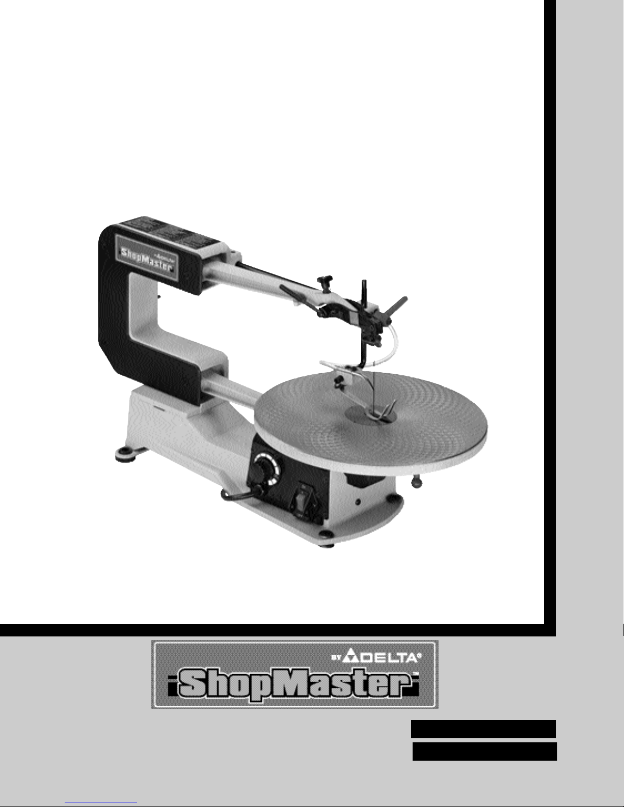
16" Variable Speed Scroll Saw
with Quickset II¤Blade
Changing Feature
(Model SM600)
PART NO. 638519-00 10-30-05
Copyright © 2005 Delta Machinery
ESPA OL: P GINA 21
To learn more about DELTA MACHINERY
visit our website at: www.deltamachinery.com.
For Parts, Service, Warranty or other Assistance,
please call
1-800-223-7278 (In Canada call 1-800-463-3582).
FRAN AIS: PAGE 41
Page 2

2
GENERAL SAFETY RULES
Woodworking can be dangerous if safe and proper operating procedures are not followed. As with all machinery, there
are certain hazards involved with the operation of the product. Using the machine with respect and caution will
considerably lessen the possibility of personal injury. However, if normal safety precautions are overlooked or ignored,
personal injury to the operator may result. Safety equipment such as guards, push sticks, hold-downs, featherboards,
goggles, dust masks and hearing protection can reduce your potential for injury . But even the best guard won’t make up
for poor judgment, carelessness or inattention. Always use common sense and exercise caution in the workshop. If a
procedure feels dangerous, don’t try it. Figure out an alternative procedure that feels safer. REMEMBER: Your
personal safety is your responsibility.
This machine was designed for certain applications only. Delta Machinery strongly recommends that this machine not
be modified and/or used for any application other than that for which it was designed. If you have any questions relative
to a particular application, DO NOT use the machine until you have first contacted Delta to determine if it can or should
be performed on the product.
Technical Service Manager
Delta Machinery
4825 Highway 45 North
Jackson, TN 38305
(IN CANADA: 505 SOUTHGATE DRIVE, GUELPH, ONTARIO N1H 6M7)
WARNING: Read and understand all instructions. Failure to follow all instructions listed below may result in
electric shock, fire and/or serious injury.
1. FOR YOUR OWN SAFETY, READ INSTRUCTION
MANUAL BEFORE OPERATING THE TOOL. Learn the
tool’s application and limitations as well as the specific
hazards peculiar to it.
2. KEEP GUARDS IN PLACE and in working order.
3. ALWAYS WEAR EYE PROTECTION.
Wear safety
glasses. Everyday eyeglasses only have impact resistant
lenses; they are not safety glasses. Also use face or dust
mask if cutting operation is dusty. These safety glasses
must conform to ANSI Z87.1 requirements. NOTE:
Approved glasses have Z87 printed or stamped on them.
4. REMOVE ADJUSTING KEYS AND WRENCHES. Form
habit of checking to see that keys and adjusting wrenches
are removed from tool before turning it “on”.
5. KEEP WORK AREA CLEAN. Cluttered areas and
benches invite accidents.
6. DON’T USE IN DANGEROUS ENVIRONMENT. Don’t
use power tools in damp or wet locations, or expose them to
rain. Keep work area well-lighted.
7. KEEP CHILDREN AND VISITORS AWAY. All children
and visitors should be kept a safe distance from work area.
8. MAKE WORKSHOP CHILDPROOF – with padlocks,
master switches, or by removing starter keys.
9. DON’T FORCE TOOL. It will do the job better and be
safer at the rate for which it was designed.
10. USE RIGHT TOOL. Don’t force tool or attachment to do
a job for which it was not designed.
11. WEAR PROPER APPAREL. No loose clothing, gloves,
neckties, rings, bracelets, or other jewelry to get caught in
moving parts. Nonslip footwear is recommended. Wear
protective hair covering to contain long hair.
12. SECURE WORK. Use clamps or a vise to hold work
when practical. It’s safer than using your hand and frees
both hands to operate tool.
13. DON’T OVERREACH. Keep proper footing and
balance at all times.
14. MAINTAIN TOOLS IN TOP CONDITION. Keep tools
sharp and clean for best and safest performance. Follow
instructions for lubricating and changing accessories.
15. DISCONNECT TOOLS before servicing and when
changing accessories such as blades, bits, cutters, etc.
16. USE RECOMMENDED ACCESSORIES. The use of
accessories and attachments not recommended by Delta
may cause hazards or risk of injury to persons.
17. REDUCE THE RISK OF UNINTENTIONAL STARTING.
Make sure switch is in “OFF” position before plugging in
power cord.
In the event of a power failure, move switch to
the “OFF” position.
18. NEVER STAND ON TOOL. Serious injury could occur if
the tool is tipped or if the cutting tool is accidentally
contacted.
19. CHECK DAMAGED PARTS. Before further use of the
tool, a guard or other part that is damaged should be
carefully checked to ensure that it will operate properly and
perform its intended function – check for alignment of
moving parts, binding of moving parts, breakage of parts,
mounting, and any other conditions that may affect its
operation. A guard or other part that is damaged should be
properly repaired or replaced.
20. DIRECTION OF FEED. Feed work into a blade or cutter
against the direction of rotation of the blade or cutter only.
21. NEVER LEAVE TOOL RUNNING UNATTENDED.
TURN POWER OFF. Don’t leave tool until it comes to a
complete stop.
22.
STAY ALERT, WATCH WHAT YOU ARE DOING, AND
USE COMMON SENSE WHEN OPERATING A POWER
TOOL. DO NOT USE TOOL WHILE TIRED OR UNDER
THE INFLUENCE OF DRUGS, ALCOHOL, OR
MEDICA TION. A moment of inattention while operating
power tools may result in serious personal injury.
23. MAKE SURE TOOL IS DISCONNECTED FROM
POWER SUPPLY while motor is being mounted, connected
or reconnected.
24. THE DUST GENERATED by certain woods and wood
products can be injurious to your health. Always operate
machinery in well ventilated areas and provide for proper
dust removal. Use wood dust collection systems whenever
possible.
25.
WARNING: SOME DUST CREATED BY
POWER SANDING, SAWING, GRINDING, DRILLING,
AND OTHER CONSTRUCTION ACTIVITIES contains
chemicals known to cause cancer, birth defects or other
reproductive harm. Some examples of these chemicals
are:
· lead from lead-based paints,
· crystalline silica from bricks and cement and other
masonry products, and
· arsenic and chromium from chemically-treated lumber.
Your risk from these exposures varies, depending on how
often you do this type of work. To reduce your exposure to
these chemicals: work in a well ventilated area, and work
with approved safety equipment, such as those dust
masks that are specially designed to filter out microscopic
particles.
SAVE THESE INSTRUCTIONS.
Refer to them often and use them to instruct others.
Page 3

ADDITIONAL SAFETY RULES FOR
SCROLL SAWS
3
WARNING: Read and understand all instructions. Failure to follow all instructions listed below may result in
electric shock, fire and/or serious injury.
SAVE THESE INSTRUCTIONS.
Refer to them often
and use them to instruct others.
1. DO NOT OPERATE your scroll saw until it is
completely assembled and installed according to the
instructions.
2. IF YOU ARE NOT thoroughly familiar with the
operation of Scroll Saws, obtain advice from your
supervisor, instructor or other qualified person.
3. YOUR SCROLL SAW MUST be securely fastened
to a stand or workbench. If there is any tendency for the
stand or workbench to move during operation, the stand
or workbench MUST be fastened to the floor.
4. THIS SCROLL SAW is intended for indoor use only.
5. MAKE SURE blade is properly tensioned before
operating saw.
6. TO AVOID blade breakage ALWAYS adjust blade
tension correctly.
7. MAKE SUREthe blade teeth point downward toward
the table.
8. NEVER turn the saw "ON" before clearing the table
of all objects (tools, scraps of wood, etc.).
9. DO NOT cut material that is too small to be safely
supported.
10. AVOID awkward hand positions where a sudden slip
could cause a hand to move into the blade.
11. ALWAYS keep hands and fingers away from blade.
12. ALWAYS adjust holddown foot for each new
operation.
13. DO NOT USE dull or bent blades.
14. DO NOT attempt to saw material that does not have
a flat surface, unless a suitable support is used.
15. MAKE "relief" cuts before cutting long curves.
16. NEVER attempt to cut a curve that is too tight for the
blade being used.
17. WHEN backing a blade out of a workpiece, the blade
may bind in the saw kerf. This is usually caused by
sawdust in the kerf. If this happens, turn "OFF" the
switch and remove plug from power source outlet.
Wedge open the kerf and back blade out of the
workpiece.
18. THE USE of attachments and accessories not
recommended by Delta may result in the risk of injuries.
19. ALWAYS hold the work firmly against the table.
20. DO NOT feed the material too fast while cutting. Only
feed the material fast enough so that the blade will cut.
21. NEVER start the Scroll Saw with the stock pressed
against the blade.
22. WHEN cutting a large workpiece MAKE SURE the
material is supported at table height.
23. USE CAUTION when cutting material which is
irregular in cross section which could pinch the blade
before the cut is completed. A piece of moulding for
example must lay flat on the table and not be permitted
to rock while being cut.
24. USE CAUTION when cutting round material such as
dowel rods or tubing. They have a tendency to roll while
being cut causing the blade to "bite." Use a V-block to
control the piece.
25. ALWAYS release blade tension before removing the
blade from the upper or lower blade holders.
26. MAKE CERTAIN table tilting lock is tightened before
starting the machine.
27. NEVER reach under the table while the machine is
running.
28. NEVER perform layout, assembly or set-up work on
the table while the saw is operating.
29. ALWAYS STOP the saw before removing scrap
pieces from the table.
30. WHEN THE TOOL IS NOT IN USE, the switch
should be locked in the “OFF” position to prevent
unauthorized use.
31. SHOULD any part of your Scroll Saw be missing,
damaged or fail in any way, or any electrical component
fail to perform properly, shut off switch and remove plug
from power supply outlet. Replace missing, damaged or
failed parts before resuming operation.
32. ADDITIONAL INFORMATION regarding the safe
and proper operation of this product is available from the
National Safety Council, 1121 Spring Lake Drive, Itasca,
IL 60143-3201, in the Accident Prevention Manual for
Industrial Operations and also in the Safety Data Sheets
provided by the NSC. Please also refer to the American
National Standards Institute ANSI 01.1 Safety
Requirements for Woodworking Machinery and the U.S.
Department of Labor OSHA 1910.213 Regulations.
Page 4
4
POWER CONNECTIONS
A separate electrical circuit should be used for your machines. This circuit should not be less than #12 wire and should
be protected with a 20 Amp time lag fuse. If an extension cord is used, use only 3-wire extension cords which have 3prong grounding type plugs and matching receptacle which will accept the machine’s plug. Before connecting the motor
to the power line, make sure the switch is in the “OFF” position and be sure that the electric current is of the same
characteristics as indicated on the machine. All line connections should make good contact. Running on low voltage will
damage the motor.
WARNING: SHOCK HAZARD. DO NOT EXPOSE THE MACHINE TO RAIN OR OPERATE THE MACHINE IN
DAMP LOCATIONS.
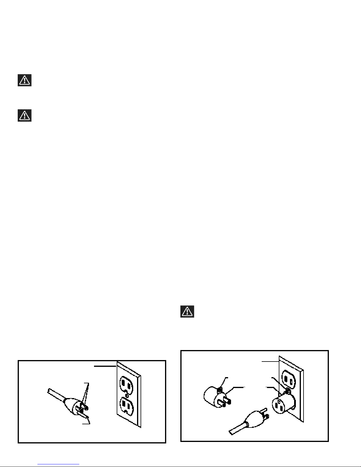
GROUNDING INSTRUCTIONS
WARNING: SHOCK HAZARD. THIS MACHINE MUST BE GROUNDED WHILE IN USE TO PROTECT THE
OPERATOR FROM ELECTRIC SHOCK. Your machine is wired for 120 volt, 60 HZ alternating current. Before
connecting the machine to the power source, make sure the switch is in the “OFF” position.
Fig. A Fig. B
GROUNDED OUTLET BOX
CURRENT
CARRYING
PRONGS
GROUNDING BLADE
IS LONGEST OF THE 3 BLADES
GROUNDED OUTLET BOX
GROUNDING
MEANS
ADAPTER
2. Grounded, cord-connected machines intended for use
on a supply circuit having a nominal rating less than 150
volts:
If the machine is intended for use on a circuit that has an
outlet that looks like the one illustrated in Fig. A, the
machine will have a grounding plug that looks like the plug
illustrated in Fig. A. A temporary adapter, which looks like
the adapter illustrated in Fig. B, may be used to connect
this plug to a matching 2-conductor receptacle as shown in
Fig. B if a properly grounded outlet is not available. The
temporary adapter should be used only until a properly
grounded outlet can be installed by a qualified electrician.
The green-colored rigid ear, lug, and the like, extending
from the adapter must be connected to a permanent
ground such as a properly grounded outlet box. Whenever
the adapter is used, it must be held in place with a metal
screw.
NOTE: In Canada, the use of a temporary adapter is not
permitted by the Canadian Electric Code.
WARNING: SHOCK HAZARD. IN ALL CASES,
MAKE CERTAIN THE RECEPTACLE IN QUESTION IS
PROPERLYGROUNDED. IF YOU ARE NOT SURE HAVE
A QUALIFIED ELECTRICIAN CHECK THE
RECEPTACLE.
1. All grounded, cord-connected machines:
In the event of a malfunction or breakdown, grounding
provides a path of least resistance for electric current to
reduce the risk of electric shock. This machine is equipped
with an electric cord having an equipment-grounding
conductor and a grounding plug. The plug must be plugged
into a matching outlet that is properly installed and
grounded in accordance with all local codes and
ordinances.
Do not modify the plug provided - if it will not fit the outlet,
have the proper outlet installed by a qualified electrician.
Improper connection of the equipment-grounding
conductor can result in risk of electric shock. The
conductor with insulation having an outer surface that is
green with or without yellow stripes is the equipmentgrounding conductor. If repair or replacement of the
electric cord or plug is necessary, do not connect the
equipment-grounding conductor to a live terminal.
Check with a qualified electrician or service personnel if the
grounding instructions are not completely understood, or if
in doubt as to whether the machine is properly grounded.
Use only 3-wire extension cords that have 3-prong
grounding type plugs and matching 3-conductor
receptacles that accept the machine’s plug, as shown in
Fig. A.
Repair or replace damaged or worn cord immediately.
Page 5

WARNING: Use proper extension cords. Make sure your extension cord is in good condition and is a 3-wire
extension cord which has a 3-prong grounding type plug and matching receptacle which will accept the machine’s plug.
When using an extension cord, be sure to use one heavy enough to carry the current of the machine. An undersized
cord will cause a drop in line voltage, resulting in loss of power and overheating. Fig. C, shows the correct gauge to use
depending on the cord length. If in doubt, use the next heavier gauge. The smaller the gauge number, the heavier the
cord.
EXTENSION CORDS
OPERATING INSTRUCTIONS
FOREWORD
ShopMaster Model SM600 is a 16" variable speed scroll saw. The variable speed range for the Model SM600 is 4001800 cutting strokes per minute. The Model SM600 offers a full 2" depth of cut for thick workpieces.
UNPACKING AND CLEANING
Carefully unpack the machine and all loose items from the shipping container(s). Remove the protective coating from all
unpainted surfaces. This coating may be removed with a soft cloth moistened with kerosene (do not use acetone, gasoline
or lacquer thinner for this purpose). After cleaning, cover the unpainted surfaces with a good quality household floor paste
wax.
NOTICE: THE MANUAL COVER PHOTO ILLUSTRATES THE CURRENT
PRODUCTION MODEL. ALL OTHER ILLUSTRATIONS ARE REPRESENTATIVE
ONLY AND MAY NOT DEPICT THE ACTUAL COLOR, LABELING OR
ACCESSORIES AND MAY BE INTENDED TO ILLUSTRATE TECHNIQUE ONLY.
5
Fig. C
MINIMUM GAUGE EXTENSION CORD
RECOMMENDED SIZES FOR USE WITH STATIONARY ELECTRIC MACHINES
Ampere Total Length Gauge of
Rating Volts of Cord in Feet Extension Cord
0-6 120
up to
25 18 AWG
0-6 120 25-50 16 AWG
0-6 120 50-100 16 AWG
0-6 120 100-150 14 AWG
6-10 120
up to
25 18 AWG
6-10 120 25-50 16 AWG
6-10 120 50-100 14 AWG
6-10 120 100-150 12 AWG
10-12 120
up to
25 16 AWG
10-12 120 25-50 16 AWG
10-12 120 50-100 14 AWG
10-12 120 100-150 12 AWG
12-16 120
up to
25 14 AWG
12-16 120 25-50 12 AWG
12-16 120
GREATER THAN 50 FEET NOT RECOMMENDED
Page 6
6
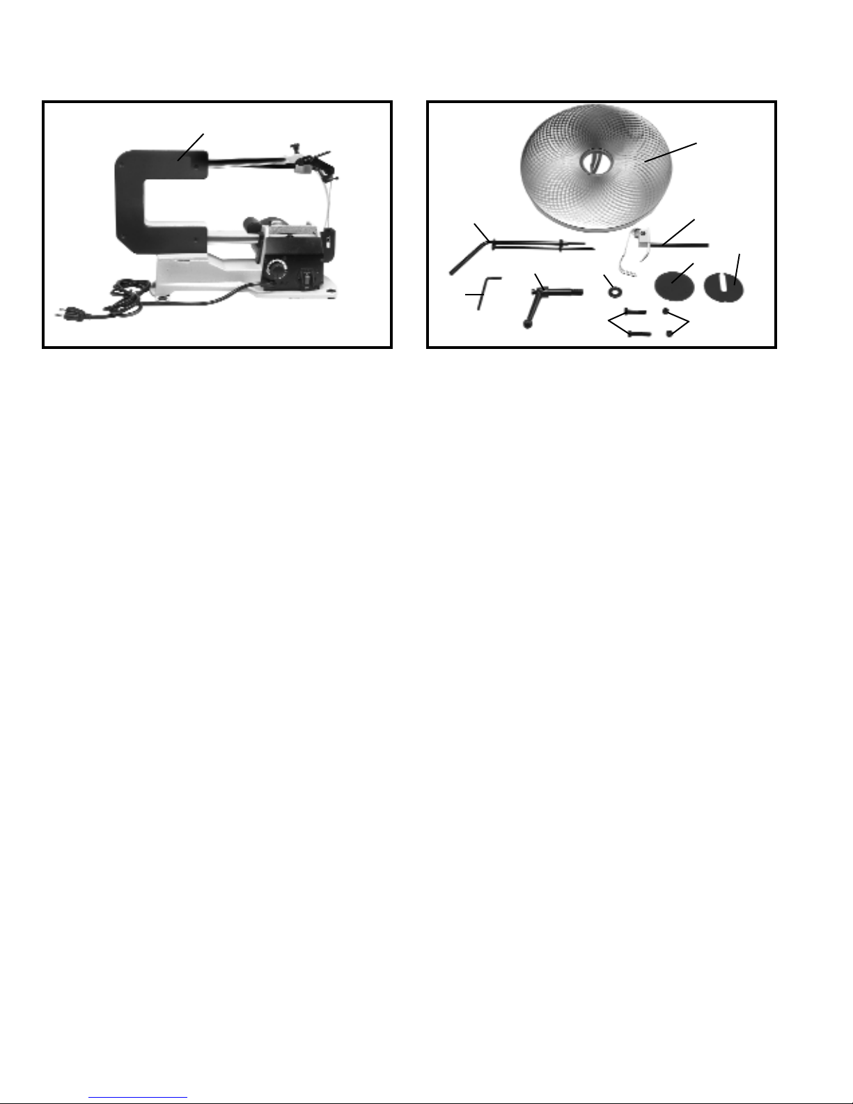
SCROLL SAW PARTS
Fig. 1
Fig. 2
Fig. 1
1. Scroll Saw with blade attached
1
Fig. 2
2. Table
3. Quickset Blade Changing Wrench
4. Holddown Rod
5. 4mm Hex Wrench
6. Locking Handle
7. M10 Flat Washer
8. Blank Table Insert
9. Table Insert
10. Special Screw M6x1x45mm (2)
11. M6 Locknut (2)
2
3
4
5
6
7
8
9
10
11
Page 7
7
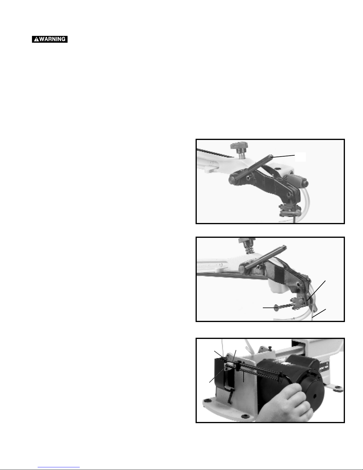
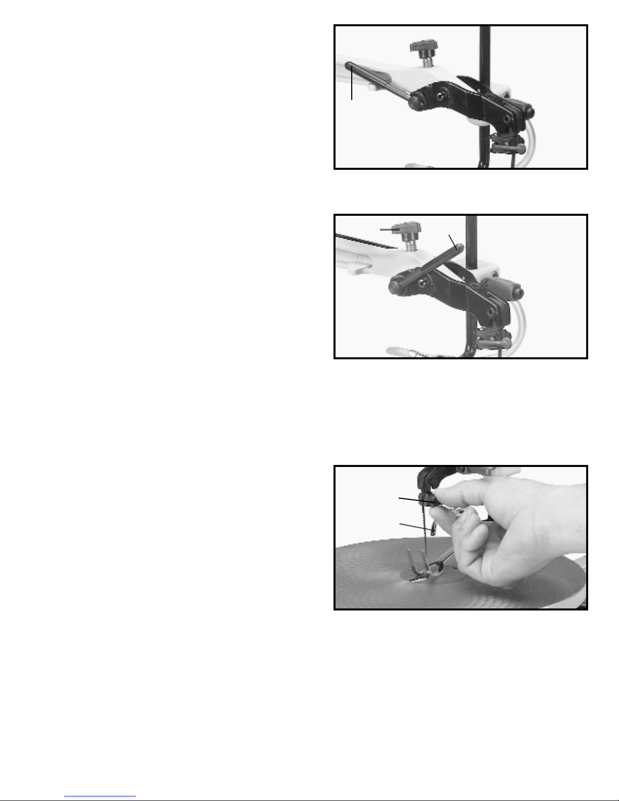
1. Remove the blade from the scroll saw.
2. Move the blade lever tension handle (A) Fig. 3, to the
foreword position as shown.
3. Push chuck locking lever (B) Fig. 4 to the rear as
shown. This will release the blade (C) from the upper
chuck assembly (D).
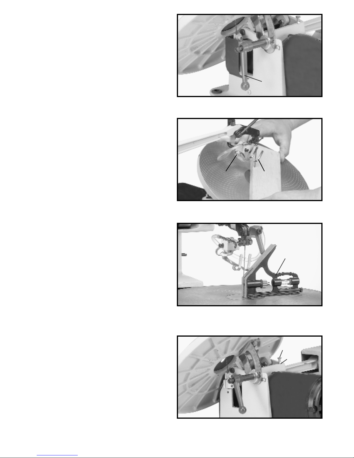
4. Insert long end (F) Fig. 5, of quickset blade changing
wrench into hole (G) in lower blade holder. This will align
wrench (H) with blade holder screw (J). Turn wrench (H)
counter-clockwise. This will release the blade from the
lower chuck assembly.
Fig. 3
A
Fig. 4
B
C
D
Fig. 5
F
G
H
J
ASSEMBLY TOOLS REQUIRED
ASSEMBLY TIME ESTIMATE
1.) 4mm hex wrench - supplied
2.) Quickset Blade Changing Wrench - supplied
3.) 10mm wrench
Less than one hour
For your own safety, do not connect the machine to the power source until the machine is
completely assembled and you read and understand the entire instruction manual.
ASSEMBLY
Page 8
8
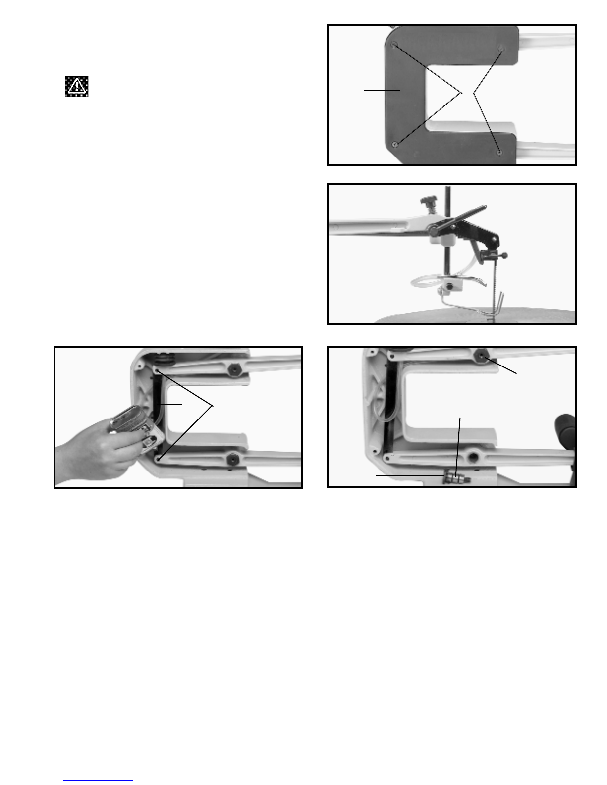
Fig. 7
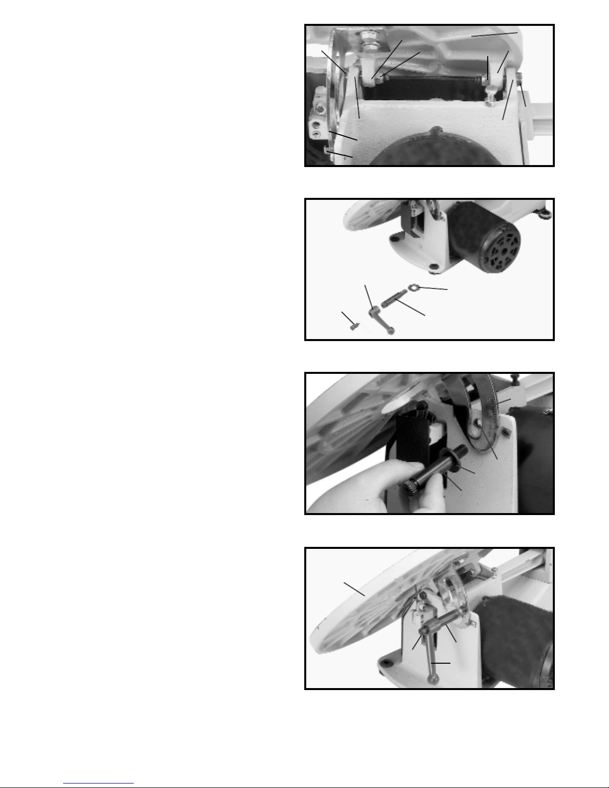
5. Position table (A) Fig. 7, on the machine as shown.
Align the two holes in the table trunnions (O) with the two
holes in the base (P) of the machine. NOTE: BEFORE
TIGHTENING THE M6x1x45mm SPECIAL SCREWS
(B) AND M6 LOCKNUTS (C) FIG. 7, MAKE SURE THE
TIL T SCALE (D), IS POSITIONED INSIDE POINTER (E)
AS SHOWN. ALSO, DO NOT COMPLETELY TIGHTEN
THE M6x1x45mm SPECIAL SCREWS (B) AND M6
LOCKNUTS (C). TABLE MUST BE ABLE TO TILT
FREELY. Fasten the table (A), to the base (P), using the
two M6x1x45mm special screws (B), and M6 locknuts
(C) as shown.
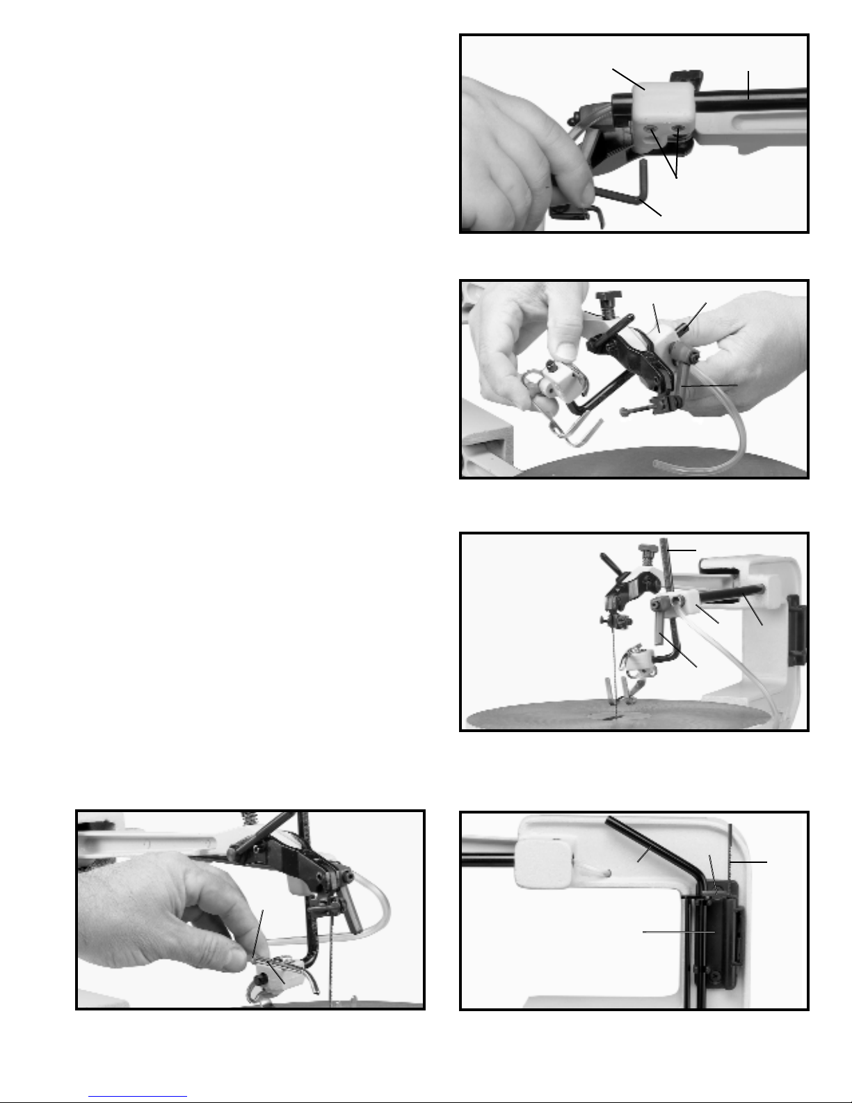
6. Disassemble the handle by unscrewing and removing screw and spring (F), and handle (G) from locking
stud (H), as shown in Fig. 8. Place a M10 flat washer (J)
on threaded end of stud (H).
7. Screw threaded end of stud (H) Fig. 9, with the M10
flat washer (J) through slot in angle of tilt scale (D) and
into tapped hole (K).
8. Place handle (G) Fig. 10, onto locking stud (H) and
fasten with screw and spring (F). Move table (A) to the
horizontal position and lock table (A), by turning handle
(G) clockwise.
B
P
O
C
A
C
O
B
P
Fig. 8
F
G
H
J
Fig. 9
Fig. 10
G
F
H
A
D
E
J
H
D
K
Page 9
9
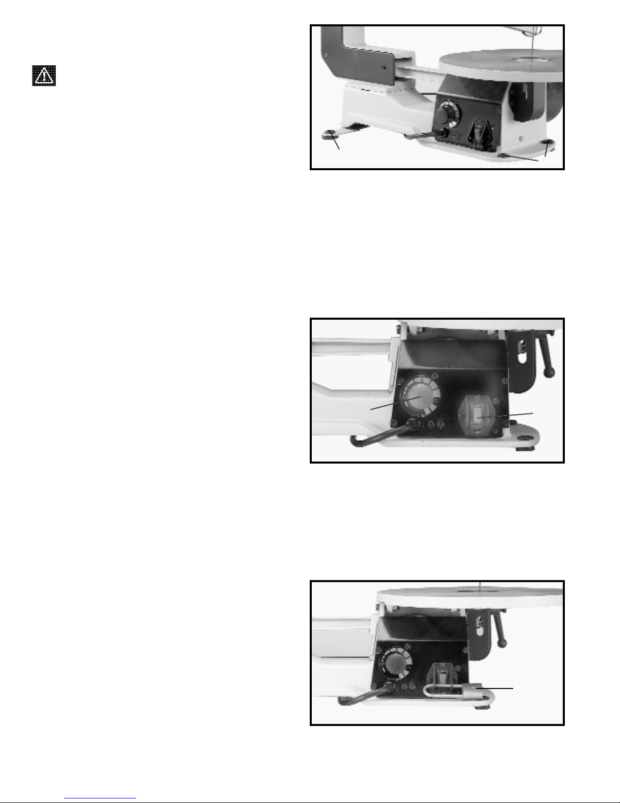
9. Using the 4mm wrench (L) Fig. 11, loosen the two
screws (P) on bottom of bracket (M) that fasten bracket
to rod (N).
Fig. 11
Fig. 12
10. Rotate bracket (M), to the position shown in Fig. 12.
Loosen lock handle (R) and insert holddown rod (S) into
hole in bracket (M), as shown.
R
M
S
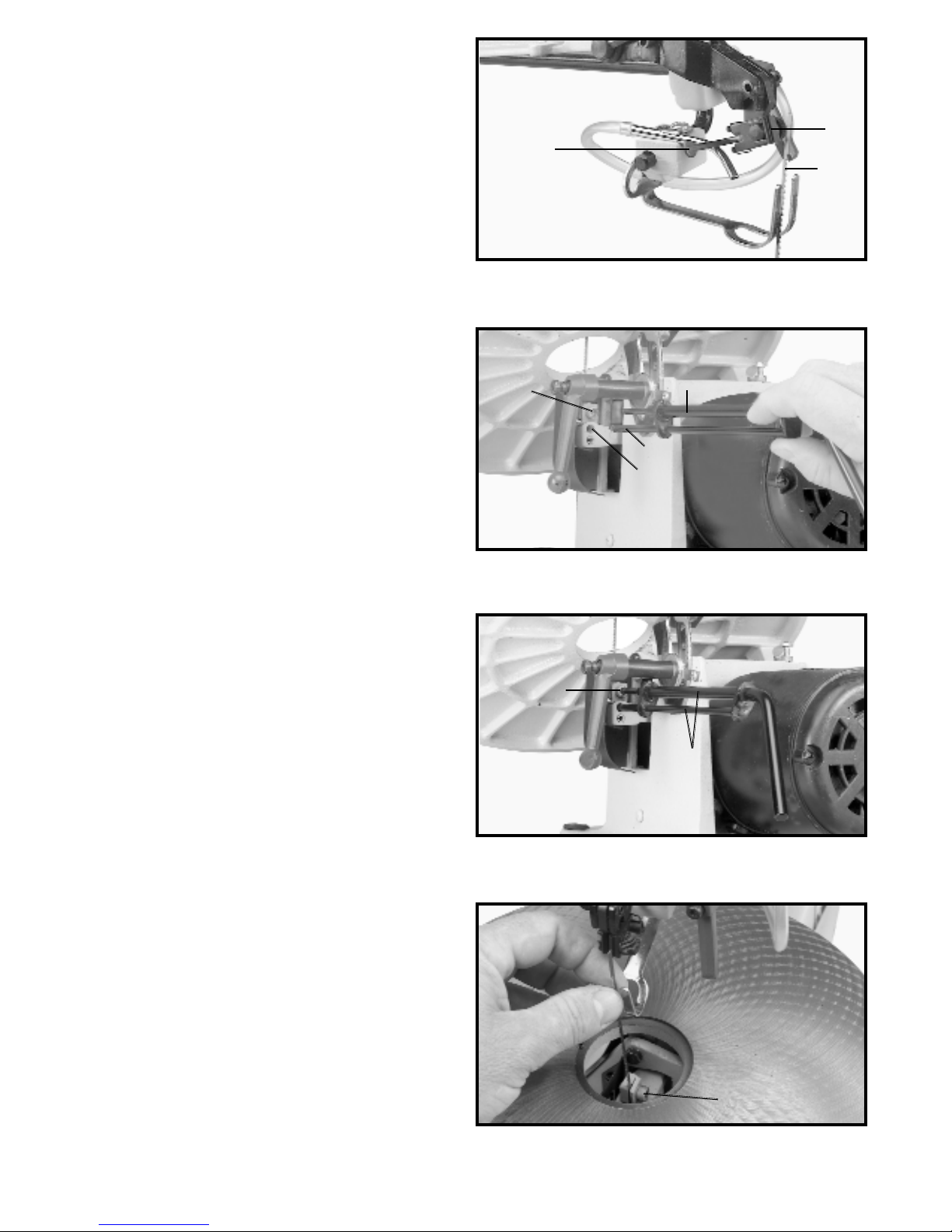
11. Rotate bracket (M) Fig. 13, back to its original
position as shown, and tighten the two screws that were
loosened in STEP 9. Then tighten lockhandle (R) to hold
rod (S) in position.
Fig. 13
M
N
S
R
12. Slide end of chip blower tube (T) Fig. 14, onto end of
air nozzle (V), as shown.
Fig. 14
T
V
Fig. 15
13. The tool holder (X) Fig. 15, is used to hold the
quickset blade changing wrench (Y), (for removing blade
from lower blade holder), 4mm allen wrench (W) and
extra blades (Z).
X
Y
W
Z
N
M
P
L
Page 10
10
FASTENING SCROLL SAW
TO SUPPORTING SURFACE
WARNING: Your scroll saw MUST be securely
fastened to a stand or workbench using the holes in the
four rubber feet, three of which are shown at (A) Fig. 16.
IMPORTANT: When mounting the saw to a stand or
workbench DO NOT over-tighten mounting bolts. Leave
some cushion in the four rubber feet (A) for absorbing
noise and vibration.
An alternate method of securing the scroll saw is to
clamp the front and side ledges of the scroll saw to a
supporting surface with C-clamps.
IMPORTANT: If there is any tendency for the stand or
workbench to move during operation, the stand or workbench must be fastened to the floor.
Fig. 16
A
A
OPERATING CONTROLS AND ADJUSTMENTS
ON-OFF AND VARIABLE
SPEED SWITCHES
The on-off switch (A) Fig. 17, and variable speed switch
(B) is located on the right side of the scroll saw base, as
shown. To turn the saw "ON," push the switch (A) up to
the “ON” position. To turn the saw "OFF", push the
switch (A) down to the “OFF” position.
The scroll saw is equipped with a variable speed control
knob (B) Fig. 17. The variable speed range is 400 to
1800 strokes per minute. When the variable speed knob
is rotated all the way to the left (counterclockwise) the
speed will be 400 strokes per minute. To increase the
speed, rotate knob (B) to the right (clockwise) until the
desired speed is obtained. When the knob (B) is rotated
all the way to the right (clockwise) the speed will be 1800
strokes per minute.
Fig. 17
A
B
LOCKING ON-OFF SWITCH
IN THE "OFF" POSITION
IMPORTANT: When the machine is not in use, the switch
should be locked in the OFF position using a padlock (C)
Fig. 18, with a 3/16" diameter shackle to prevent
unauthorized use.
Fig. 18
C
Page 11

11
TABLE INSERT
The table insert (A) can be assembled to the saw table
with the opening in the insert pointing to the front of the
table, as shown in Fig. 19, or to the right as shown in Fig.
20.
With the table in the level position, 90 degrees to the
blade, the insert should be positioned, as shown in Fig.
19. This allows for the blade to be pivoted forward after it
is unclasped from the top blade holder, enabling you to
quickly insert the blade into the next hole in a pattern
when doing inside-cutting.
When tilting the table for bevel cutting operations the
insert (A) should be positioned as shown in Fig. 20. This
allows for clearance of the blade when the table is tilting.
Fig. 19
Fig. 20
A
A
Fig. 21
A
B
A table insert blank (B) Fig. 21, is supplied as standard
equipment with your scroll saw and can be used when
cutting very small workpieces to give added support to
the bottom of the workpiece. Cut a slot into the blank and
replace the standard insert (A) with the blank (B). The
slot cut into the blank (B) will only be as wide as the
blade giving maximum support to the bottom of the
workpiece.
CHANGING BLADES
1. WARNING: DISCONNECT MACHINE FROM
POWER SOURCE.
2. Remove table insert (A) Fig. 22, and release blade
tension by pulling tension lever (B) forward, as shown.
A
B
Fig. 22
Page 12
12
3. Push chuck locking lever (C) Fig. 23, to the rear as
shown. This will release the blade (D) from the upper
chuck (E).
Fig. 23
C
D
E
4. Insert long end (F) Fig. 24, of quickset blade wrench
into hole (G) in lower blade holder. This will align wrench
(H) with blade holder screw (J).
Fig. 24
G
F
J
H
5. Fig. 25 illustrates the quickset blade changing
wrench (K) engaged with the lower blade holder
assembly. Turn wrench counterclockwise to loosen
screw (J) Figs. 24 and 25, and remove blade from lower
chuck.
6. Insert new blade into the lower and upper blade
holders in the same manner, making certain the blade
teeth are pointing down toward the table.
7. Tighten screw (J) Fig. 26, in lower blade guard
assembly.
8. Push chuck locking lever (C) Fig. 23, to the foreword
position, to lock the blade in the upper blade holder
assembly.
10. Apply blade tension by referring to the following
section "ADJUSTING BLADE TENSION."
Fig. 25
Fig. 26
K
J
J
9. Replace the table insert that was removed in STEP
2.
Page 13
13
ADJUSTING BLADE
TENSION
Tension is applied to the blade when the blade tension
lever (A) Fig. 27, is in the rear position, as shown. When
the lever (A) is moved forward, as shown in Fig. 28,
blade tension is released.
When adjusting blade tension, lever (A) should be in the
forward position, as shown in Fig. 28. To increase blade
tension, turn knob (B) Fig. 28, clockwise and to decrease
blade tension, turn knob (B) counterclockwise. NOTE: It
is necessary to adjust the blade tension knob (B) only
when the blade is removed from both upper and lower
blade holders and a new or different type of blade is
assembled to the holders. It is not necessary to adjust
blade tension when the blade is removed and replaced in
only the upper blade holder as in performing inside
cutting operations.
Adjusting the blade for proper tension is usually
accomplished by trial and error. One method is to pull
back on the blade tension lever (A) Fig. 28, the blade
should start to have tension (resistance) when the blade
tension lever is half way between open Fig. 28, and
closed Fig. 27. Finer blades require more tensioning
while thicker blades require less tension.
Fig. 27
Fig. 28
A
A
B
ADJUSTING
CLAMPING ACTION OF
UPPER BLADE HOLDER
Different widths of scroll saw blades will make it
necessary to adjust the clamping action of the upper
blade holder. It should be noted, however, that very little
adjustment is necessary and very little clamping force is
required to hold the blade.
1. Move the chuck locking lever (C) Fig. 23, to the rear
(open) position, as shown.
2. Turn locknut (C) Fig. 29, clockwise to tighten and
counterclockwise to loosen the clamping action of the,
blade holder. Very little movement of locknut (C) is
necessary.
Fig. 29
A
C
Page 14
14
Fig. 30
Fig. 31
TILTING THE TABLE
The table on your scroll saw can be tilted 45 degrees to
the left for bevel cutting operations by loosening table
lock handle (A) Fig. 30, tilt the table to the desired angle
and tighten lock handle (A).
When bevel cutting, the holddown (B) Fig. 31, can be
adjusted to lay flat on the stock by loosening screw (C)
and tilting the holddown (B) accordingly. Then tighten
screw (C).
A
ADJUSTING THE TABLE
Fig. 32
Fig. 33
1. Loosen the table locking handle, and move the table
all the way to the right.
2. Using a square (A) Fig. 32, check to see if the table
is 90 degrees to the saw blade, as shown.
3. If the table is not at 90 degrees to the blade, adjust
the table accordingly making certain screw (B) Fig. 33,
contacts bottom of table surface when table is 90
degrees to the blade. Screw (B) can be adjusted by
loosening nut (C), thread screw (B) in or out the desired
distance and tighten nut (C).
A
B
C
C
B
Page 15
15
ADJUSTING HOLDDOWN
The holddown (A) Fig. 34, should be adjusted so it
contacts the top surface of the work being cut by
loosening lock handle (B) and moving holddown rod (C)
up or down. Then tighten lock handle (B).
ADJUSTING DUST BLOWER
The dust blower (A) Fig. 35, may be moved to direct air
to the most effective point on the cutting line by loosening
screw (B), adjust nozzle (A), and tighten screw (B).
Fig. 34
A
B
C
Fig. 35
B
A
Page 16
16
INSIDE CUTTING
Inside cutting is where the blade must be threaded through a hole in the workpiece. The Shopmaster 16" Scroll Saw
has the capability of performing this operation quickly and easily as follows:
Fig. 36
Inside cutting can be accomplished quickly with the saw.
In Fig. 36, the operator has just completed one of the
inside cuts and must move to the next hole.
Fig. 37
Fig. 38
Loosen lock handle (A) Fig. 37, and raise the spring
holddown (B). Release blade tension by moving tension
lever (C) forward and loosen upper blade holder by
moving lever (D) to the rear as shown. This will release
the blade (E). Insert the blade (E) into the next hole in the
pattern, as shown.
Place blade (E) Fig. 38, back into the upper blade holder
and tighten blade by moving lever (D) forward. Move
tension lever (C) to the rear as shown and lower spring
holddown (B). You are ready to make the next inside cut.
FOLLOWING A LINE
WARNING: CUT HAZARD: Keep hands away from blade. With your scroll saw you should be able to cut a straight
or curved line with ease. Most beginners will experience blade wandering; however, they eventually learn to control it
as they become more familiar with the machine. Use scrap material to practice cuts before starting a project. This
enables you to develop your own way of cutting and you will find out what you can and cannot do with your saw.
Always hold the work firmly against the table and do not feed the workpiece too fast while cutting. Feed the workpiece
only fast enough so that the blade will cut. Scroll saws cut faster across the grain than they do with the grain. Allow for
this tendency when cutting patterns that shift rather quickly from with-the-grain cuts to cross-grain cuts.
Make "relief" cuts before cutting long curves and never attempt to cut a curve that is too tight for the blade being used.
C
D
A
B
E
D
E
B
C
Page 17
17
LUBRICATION
Fig. 39
Fig. 40
Fig. 42
1. WARNING: DISCONNECT MACHINE FROM
POWER SOURCE.
2. Remove four screws (A) Fig. 39, and remove side
panel (B) from the scroll saw.
4. Lubricate the shafts of two special screws (D) Fig.
41, with a few drops of light machine oil in the areas
where they pass through the connecting link (E). NOTE:
DO NOT REMOVE SPECIAL SCREWS TO LUBRICATE.
5. Remove two pivot bolts (F) Fig. 42.
6. Thoroughly clean grease from shafts (G) Fig. 42, of
both pivot bolts (F) and lubricate shafts (G) with a few
drops of light machine oil.
7. Reassemble two pivot bolts (F) Fig. 42, to machine.
8. Replace side panel removed in STEP 2 and reapply
tension to the blade.
3. Release blade tension by pulling tension lever (C)
Fig. 40, forward as shown.
TROUBLESHOOTING - BLADE BREAKAGE
Blade breakage is usually caused by one or more of the following:
1. Bending the blade during installation.
2. Improper blade tension.
3. Improper blade selection for the work being cut.
4. Forcing the work into the blade too rapidly.
5. Cutting too sharp a turn for the blade being used.
6. Improper blade speed.
It is recommended that the scroll saw be oiled after
each 20 hours of use, as follows:
CHOICE OF BLADE AND SPEED
Y our scroll saw will accept a wide variety of 5" flat end blades and can be operated at any speed from 400 to 1800 cutting
strokes per minute. Consider the following as a general guideline for selecting a blade and operating speed.
1. Use a finer blade for cutting thin workpieces, for hard materials, or when a smoother cut is required.
2. Use a coarser blade for cutting thick workpieces, when making straight cuts or for medium to soft materials.
3. Use a blade that will have 2 teeth in the workpiece at all times.
4. Most blade packaging is marked with the size of the wood the blade is intended to cut and the minimum radius
which can be cut with that blade.
5. Slower speeds are generally more effective than faster speeds when using thin blades and making intricate cuts.
6. Always start at a slow speed and gradually increase the speed until the optimum cutting speed is obtained.
Fig. 41
A
B
C
E
D
F
F
G
Page 18

18
NOTES
Page 19

19
NOTES
Page 20

Two Year Limited Warranty
Delta will repair or replace, at its expense and at its option, any Delta machine, machine part, or machine accessory which
in normal use has proven to be defective in workmanship or material, provided that the customer returns the product
prepaid to a Delta factory service center or authorized service station with proof of purchase of the product within two
years and provides Delta with reasonable opportunity to verify the alleged defect by inspection. Delta may require that
electric motors be returned prepaid to a motor manufacturer s authorized station for inspection and repair or replacement.
Delta will not be responsible for any asserted defect which has resulted from normal wear, misuse, abuse or repair or
alteration made or specifically authorized by anyone other than an authorized Delta service facility or representative. Under
no circumstances will Delta be liable for incidental or consequential damages resulting from defective products. This
warranty is Delta s sole warranty and sets forth the customer s exclusive remedy, with respect to defective products; all
other warranties, express or implied, whether of merchantability, fitness for purpose, or otherwise, are expressly
disclaimed by Delta.
Printed in China
PARTS, SERVICE OR WARRANTY ASSISTANCE
All Delta Machines and accessories are manufactured to high quality standards and are serviced by a network
of Porter-Cable · Delta Factory Service Centers and Delta Authorized Service Stations. To obtain additional
information regarding your Delta quality product or to obtain parts, service, warranty assistance, or the location
of the nearest service outlet, please call 1-800-223-7278 (In Canada call 1-800-463-3582).
ACCESSORIES
A complete line of accessories is available from your Delta Supplier, Porter-Cable · Delta Factory Service Centers,
and Delta Authorized Service Stations. Please visit our Web Site
www.deltamachinery.com for a catalog or for
the name of your nearest supplier.
WARNING: Since accessories other than those offered by Delta have not been tested
with this product, use of such accessories could be hazardous. For
safest
operation, only Delta recommended accessories should be used with this product.
20
Page 21

Para obtener más información sobre Delta Machinery,
visite nuestro sitio web en: www.deltamachinery.com
Para las piezas, el servicio, la garant a o la otra ayuda
llaman por favor
1-800-223-7278 (en la llamada 1-800-463-3582 de Canada).
MANUAL DE INSTRUCCIONES
Sierra de Calar de
16 pulg. de Velocidad Variable
(Modelo SM600)
638519-00 - 10-30-05
Copyright © 2005 Delta Machinery
ENGLISH: PAGE 1
Page 22

22
NORMAS DE SEGURIDAD GENERALES
La ebanistería puede ser peligrosa si no se acatan procedimientos seguros y apropriados. Al igual que con todo tipo de maquinaria, la operación
del producto envuelve ciertos peligros. El uso de la máquina con respecto y precaución reducirá considerablement la posibilidad del
lesionamiento personal. Sin embargo, el hacer caso omiso de las precauciones normales de seguridad puede tener por resultado el
lesionamiento del operario. El equipo de seguridad, así como los protectores, varillas de empuje, retenes, tablas de biselado, gafas, caretas
contra el polvo y protección auditiva pueden reducir el lesionamiento potencial. No obstante, el mejor protector no puede compensar por la
falta de juicio, la falta de cuidado o la distracción. Utilice siempr
e su sentido común y tenga cuidado en el taller. Si un procedimiento parece ser
peligroso, no lo intente.
Trate de ingeniar un procedimiento alternado que cuente con mayor grado de seguridad. NO OLVIDE: Usted es responsable
de su propia seguridad.
Esta máquina ha sido diseñada para ciertos usos solamente. Delta Machinery le recomienda enérgicamente que no se modifique esta máquina
ni que tampoco se le utilice para cualquier uso que no sea el indicado por su diseño. Si tiene cualquier pregunta con respecto a un uso
específico, NO UTILICE la máquina hasta haberse comunicado con Delta para determinar si se puede o si se debe realizar sobre el producto.
Technical Service Manager
Delta Machinery
4825 Highway 45 North
Jackson, TN 38305
(EN CANADA: 505 SOUTHGATE DRIIVE, GUELPH, ONTARIO N1H 6M7)
ADVERTENCIA: LEA Y COMPRENDA TODAS LAS ADVERTENCIAS Y LAS INSTRUCCIONES DE OPERACI N
ANTES DE UTILIZAR ESTE EQUIPO. El incumplimiento de cualquiera de las
instrucciones enumeradas abajo puede provocar descarga el ctrica, incendio o lesiones
personales graves o da os a la propiedad.
1. PARA SU PROPIA SEGURIDAD, LEA EL MANUAL DE
INSTRUCCIONES ANTES DE UTILIZAR LA HERRAMIENTA.
Aprenda los usos y limitaciones de la herramienta al igual que los
peligros particulares que implican su uso.
2. MANTENGA LOS RESGUARDOS EN SU SITIO y en buen
estado.
3. SIEMPRE USE PROTECCION OCULAR. Utilice gafas de
seguridad (deben cumplir con ANSI Z87.1). Las gafas comunes sólo
tienen lentes resistentes al impacto; no son gafas de seguridad.
También haga uso de una careta o máscara si la operación de corte
es polvorosa.
4. QUITE LAS CLAVIJAS Y LLAVES DE AJUSTE. Acostúmbrese
a revisar que las clavijas y llaves de ajuste hayan sido quitadas de la
herramienta antes de encenderla.
5. MANTENGA LIMPIA SU AREA DE TRABAJO. Las zonas y
banquillos desordenados propician accidentes.
6. NO LA UTILICE EN UN ENTORNO PELIGROSO. No utilice
herramientas eléctricas en sitios húmedos o mojados. No las
exponga a la lluvia. Mantenga el área de trabajo bien alumbrada.
7. MANTENGA A LOS N I OS Y VISITANTES ALEJADOS. Todos
los niños y visitantes deben ser alejados a una distancia segura del
área de trabajo.
8. HAGA SU TALLER A PRUEBA DE NI O S con cerrojos,
interruptores maestros o quitando las llaves de encendido.
9. NO FUERCE LA HERRAMIENTA. Realizará su trabajo mejor y
será más segura a la tasa de operación para la cual fue diseñada.
10. UTILICE LA HERRAMIENTA DEBIDA. No fuerce la herramienta
o aditamento a realizar una labor para la cual no fue diseñada.
11. UTILICE LA INDUMENTARIA DEBIDA. No vista ropa suelta,
guantes, corbatas, sortijas, pulseras u otras prendas que puedan
quedar atrapadas en las piezas movibles. Se recomienda el uso de
calzado antiderrapante. Utilice gorros protectivos para contener el
cabello largo.
12. ASEGURE LA LABOR. Utilice abrazaderas o un tornillo para
detener su trabajo cuando sea práctico. Es más seguro que el uso
de su mano y le deja ambas manos libres para usar la herramienta.
13. NO SE EXTIENDA DEMASIADO. Mantenga el equilibro y
posición establecida en todo momento.
14. MANTENGA SUS HERRAMIENTAS EN BUEN ESTADO.
Mantenga las herramientas afiladas y limpias para un rendimiento
mejor y más seguro. Siga las instrucciones para el engrase y cambio
de accesorios.
15. DESCONECTE LAS HERRAMIENTAS antes de rendir servicio
y cuando cambie accesorios tales como hojas, brocas, cuchillas, etc.
16. UTILICE LOS ACCESORIOS RECOMENDADOS. El uso de
accesorios que no sean recomendados por Delta puede resultar en
peligros o riesgos de lesionamiento personal.
17. REDUZCA EL RIESGO DE ARRANQUES NO
INTENCIONALES. Asegúrese de que el interruptor esté en la
posición de APAGADO antes de enchufar el cordón de potencia. En
el acontecimiento de un apagón, mueva el interruptor al “OFF”
coloque.
18. NO SE PARE JAMAS SOBRE LA HERRAMIENTA. Pueden
sobrevenir heridas graves si la herramienta se inclina o si se hace
contacto accidental con el instrumento cortante.
19. REVISE LA PIEZAS DA ADAS. Antes de proseguir con el uso
de la herramienta, un resguardo u otra pieza que esté dañada debe
ser revisada cuidadosamente para asegurar que funcionará
correctamente y realizará su función propuesta–revise el
alineamiento de las piezas movibles, las ataduras de las piezas
movibles, el montaje y cualquier otra condición que pueda afectar su
operación. Un resguardo o cualquier otra pieza dañada debe ser
reparada debidamente o repuesta.
20. DIRECCION DE ALIMENTACION. Alimente el trabajo hacia la
hoja o cuchilla contra la dirección de rotación de la hoja o la cuchilla
solamente.
21. JAMAS DEJE LA HERRAMIENTA FUNCIONANDO SIN
ATENCION. APAGUE LA ENERGIA. No se separe de la herramienta
hasta que ésta se haya detenido por completo.
22.
MANT NGASE ALERTA; PRESTE ATENCI N A LO QUE
EST HACIENDO Y PROCEDA L GICAMENTE CUANDO
OPERE UNA HERRAMIENTA EL CTRICA. NO USE LA
HERRAMIENTA CUANDO EST CANSADO NI BAJO LA
INFLUENCIA DE MEDICACI N, ALCOHOL O DROGAS. Un
momento de inatención cuando esté usando una herramienta
eléctrica puede resultar en una grave herida personal.
23. ASEGURESE DE QUE LA HERRAMIENTA ESTE
DESCONECTADA DE LA FUENTE DE ENERGIA mientras que se
esté montando, conectando o reconectando el motor.
24. EL POLVO GENERADO por ciertas maderas y productos de
madera puede ser perjudicial a su salud. Siempre opere la
maquinaria en áreas bien ventiladas y proporcione la remoción de
polvo debida. Utilice sistemas de colección de polvo de madera
siempre que sea posible.
25.
ADVERTENCIA: CIERTO POLVO GENERADO POR EL
LIJADO, ASERRADO, AMOLADO Y TALADRADO
MEC NICOS, Y POR OTRAS ACTIVIDADES DE
CONSTRUCCI N, contiene agentes químicos que se sabe que
causan cáncer, defectos de nacimiento u otros daños sobre la
reproducción. Algunos ejemplos de estos agentes químicos son:
· Plomo de pinturas a base de plomo,
· Sílice cristalina de ladrillos y cemento y otros
productos de mampostería, y
· Arsénico y cromo de madera tratada químicamente.
Su riesgo por causa de estas exposiciones varía, dependiendo
de con cuánta frecuencia realice este tipo de trabajo. Para reducir
su exposición a estos agentes químicos: trabaje en un área bien
ventilada y trabaje con equipo de seguridad aprobado, como por
ejemplo máscaras antipolvo que estén diseñadas especialmente
para impedir mediante filtración el paso de partículas
microscópicas.
GUARDE ESTAS INSTRUCCIONES. Refiérase a ellas con
frecuencia y utilícelas para adiestrar a otros.
Page 23

REGLAS DE SEGURIDAD ADICIONALES PARA
LAS SIERRAS DE CALAR
1. NO ACCIONE SU SIERRA DE CALAR HASTA que esté
completamente ensamblada e instalada de acuerdo con las
instrucciones.
2. SI NO ESTA completamente familiarizado con el
funcionamiento de las sierras de calar, solicite el consejo de su
supervisor, instructor u otra persona calificada.
3. SU SIERRA DE CALAR DEBE estar afianzada con
seguridad a un estante o banquillo de taller. Si el estante o
banquillo tiene la tendencia de moverse durante el funcionamiento, el estante o banquillo DEBE ser fijado al piso.
4. ESTA SIERRA DE CALAR es para el uso en interiores
sola-mente.
5. ASEGURESE que la hoja esté debidamente tensionada
antes de accionar la sierra.
6. PARA EVITAR la rotura de la hoja, ajuste la tensión de
hoja debidamente SIEMPRE.
7. ASEGURESE que los dientes de la hoja apunten hacia
abajo en dirección de la mesa.
8. JAMAS encienda la sierra sin antes haber quitado todo
tipo de objetos de la mesa (herramientas, pedazos de madera,
etc.).
9. NO CORTE material que sea demasiado pequeño para
afianzar con seguridad.
10. EVITE posiciones de mano en las cuales un desliz puede
hacer que la mano entre en contacto con la hoja.
11. MANTENGA las manos alejadas de la hoja SIEMPRE.
12. AJUSTE el pie sujetador para cada operación nueva
SIEMPRE.
13. NO UTILICE hojas romas o torcidas.
14. NO INTENTE cortar material que no tenga una superficie
plana, a no ser que se utilice el respaldo debido.
15. HAGA cortes de "desahogo" antes de cortar curvas
largas.
16. JAMAS intente cortar una curva demasiado apretada
para la hoja que se utiliza.
17. CUANDO retire la hoja de una pieza, la hoja puede quedar
atrapada en la entalladura. Esto es comúnmente el resultado
del acerrín en la entalladura. De suceder esto, APAGUE el
interruptor y quite el enchufe de la fuente de potencia. Abra la
entalladura con una cuña y retire la hoja de la pieza.
18. EL USO de accesorios que no sean los recomendados
por Delta puede resultar en el riesgo de lesionamientos.
19. SOSTENGA la pieza firmemente contra la mesa
SIEMPRE.
20. NO ALIMENTE el material muy rápidamente mientras que
corta. Alimente el material lo suficientemente rápido para que
la hoja pueda cortar.
21. JAMAS encienda la sierra de calar con el material
haciendo contacto con la hoja.
22. CUANDO esté cortando una pieza grande, ASEGURESE
que el material está afianzado a la altura de la mesa.
23. TENGA CUIDADO al cortar material con un corte
transversal irregular, que pueda atrapar la hoja antes de
completar el corte. Por ejemplo, una pieza de moldeado debe
yacer de plano sobre la mesa, y no debe permitirse que se
mece durante el corte.
24. TENGA CUIDADO al cortar material circular, así como
pasadores de unión y tubos, ya que tienden a rodar al ser
cortados, haciendo que la sierra "muerda". Utilice un bloque
en "V" para controlar la pieza.
25. SUELTE SIEMPRE la tensión de hoja antes de remover la
hoja de los detentores de hoja superior y inferior.
26. ASEGURESE que el cierre de inclinación de la mesa esté
apretado antes de arrancar la máquina.
27. JAMAS trate de alcanzar debajo de la mesa mientras que
la máquina está funcionando.
28. JAMAS realice trazados, ensamblaje o trabajos de
montaje sobre la mesa mientras que la sierra esté
funcionando.
29. DETENGA SIEMPRE la hoja antes de quitar los desechos
de la mesa.
30. CUANDO LA SIERRA PARA CORTAR INGLETES NO SE
EST UTILIZANDO, el interruptor debe bloquearse en la
posición de apagado para impedir el uso no autorizado de la
sierra.
31. SI CUALQUIER pieza de su sierra de calar llegase a faltar,
dañarse o fallar de cualquier modo, o si cualquier componente
eléctrico deja de funcionar debidamente, apague el interruptor
y quite el enchufe de la fuente de potencia. Reemplace las
piezas que falten, o estén dañadas o fallidas antes de
reencaminar la operación.
32. INFORMACION ADICIONAL sobre el funcionamiento
seguro y apropiado de este producto puede obtenerse de
parte del National Safety Council, 1121 Spring Lake Drive,
Itasca, IL 60143-3201, en el Manual de Prevención de
Accidentes para Operaciones Industriales, y también en las
hojas de seguridad proporcionadas por la NSC. Haga el favor
de referirse también a los Reglamentos de Seguridad para
Maquinaria de Ebanistería, ANSI 01.1 del American National
Standards Institute, y los reglamentos OSHA 1910.213 del
U.S. Department of Labor
.
ADVERTENCIA: LEA Y COMPRENDA TODAS LAS ADVERTENCIAS Y LAS INSTRUCCIONES DE
OPERACI N ANTES DE UTILIZAR ESTE EQUIPO. El incumplimiento de cualquiera de las
instrucciones enumeradas abajo puede provocar descarga el ctrica, incendio o lesiones
personales graves o da os a la propiedad.
GUARDE ESTAS INSTRUCCIONES.
Refiérase a ellas con frecuencia
y utilícelas para adiestrar a otros.
23
Page 24

CONEXIONES A LA FUENTE DE ALIMENTACI N
Debe utilizarse un circuito eléctrico independiente para las máquinas. Este circuito debe tener alambre de no menos
del No. 12 y debe estar protegido con un fusible de acción retardada de 20 A. Si se utiliza un cordón de extensión,
utilice únicamente cordones de extensión de tres alambres que tengan enchufes de tipo de conexión a tierra con tres
terminales y un receptáculo coincidente que acepte el enchufe de la máquina. Antes de conectar el motor a la línea de
alimentación, asegúrese de que el interruptor esté en la posición de apagado y cerciórese de que la corriente eléctrica
tenga las mismas características que las que estén indicadas en la máquina. Todas las conexiones a la línea de
alimentación deben hacer buen contacto. El funcionamiento a bajo voltaje dañará el motor.
ADVERTENCIA: RIESGO DE DESCARGA EL CTRICA.NO EXPONGA LA M QUINA A LA LLUVIA NI LA
UTILICE EN LUGARES H MEDOS.
ESPECIFICACIONES DEL MOTOR
La máquina está cableada para corriente alterna de 120 V, 60 Hz. Antes de conectar la máquina a la fuente de
alimentación, asegúrese de que el interruptor esté en la posición de apagado.
INSTRUCCIONES DE CONEXI N A TIERRA
ADVERTENCIA: RIESGO DE DESCARGA EL CTRICA.ESTA M QUINA DEBE ESTAR CONECTADA A TIERRA
MIENTRAS SE EST UTILIZANDO, PARA PROTEGER AL OPERADOR CONTRA LAS DESCARGAS EL CTRICAS.
1. Todas las máquinas conectadas con cordón
conectadas a tierra:
En caso de mal funcionamiento o avería, la conexión a
tierra proporciona una ruta de resistencia mínima para la
corriente eléctrica, con el fin de reducir el riesgo de
descargas eléctricas. Esta máquina está equipada con
un cordón eléctrico que tiene un conductor de conexión
a tierra del equipo y un enchufe de conexión a tierra. El
enchufe debe enchufarse en un tomacorriente
coincidente que esté instalado y conectado a tierra
adecuadamente, de acuerdo con todos los códigos y
ordenanzas locales.
No modifique el enchufe suministrado. Si el enchufe no
cabe en el tomacorriente, haga que un electricista
calificado instale el tomacorriente apropiado.
La conexión inapropiada del conductor de conexión a
tierra del equipo puede dar como resultado riesgo de
descargas eléctricas. El conductor con aislamiento que
tiene una superficie exterior de color verde con o sin
franjas amarillas es el conductor de conexión a tierra del
equipo. Si es necesario reparar o reemplazar el cordón
eléctrico o el enchufe, no conecte el conductor de
conexión a tierra del equipo a un terminal con corriente.
Consulte a un electricista competente o a personal de
servicio calificado si no entiende completamente las
instrucciones de conexión a tierra o si tiene dudas en
cuanto a si la máquina está conectada a tierra
apropiadamente.
Utilice únicamente cordones de extensión de tres
alambres que tengan enchufes de tipo de conexión a
tierra con tres terminales y receptáculos de tres
conductores que acepten el enchufe de la máquina, tal
como se muestra en la Fig. A.
Repare o reemplace inmediatamente los cordones
dañados o desgastados.
2. Máquinas conectadas con cordón conectadas a tierra
diseñadas para utilizarse en un circuito de alimentación
que tenga una capacidad nominal de menos de 150 V:
Si la máquina está diseñada para utilizarse en un circuito
que tenga un tomacorriente parecido al que se ilustra en
la Fig. A, la máquina tendrá un enchufe de conexión a
tierra que se parece al enchufe ilustrado en la Fig. A.
Puede utilizarse un adaptador temporal, que se parece
al adaptador ilustrado en la Fig. B, para conectar este
enchufe a un receptáculo coincidente de dos
conductores, tal como se muestra en la Fig. B, si no se
dispone de un tomacorriente conectado a tierra
apropiadamente. El adaptador temporal debe utilizarse
solamente hasta que un electricista calificado pueda
instalar un tomacorriente conectado a tierra
apropiadamente. La orejeta, lengüeta, etc., rígida de
color verde que sobresale del adaptador debe
conectarse a una toma de tierra permanente, como por
ejemplo una caja tomacorriente conectada a tierra
adecuadamente. Siempre que se utilice un adaptador,
debe sujetarse en su sitio con un tornillo de metal.
NOTA: En Canad , el uso de un adaptador temporal
no est permitido por el C digo El ctrico
Canadiense.
ADVERTENCIA: RIESGO DE DESCARGA
EL CTRICA.EN TODOS LOS CASOS, ASEG RESE
DE QUE EL RECEPT CULO EN CUESTI N EST
CONECTADO A TIERRA ADECUADAMENTE. SI NO
EST SEGURO, HAGA QUE UN ELECTRICISTA
CALIFICADO COMPRUEBE EL RECEPT CULO.
24
Page 25

Fig. A
Fig. B
CAJA TOMACORRIENTE
CONECTADA A TIERRA
TERMINALES
QUE LLEVAN
CORRIENTE
EL TERMINAL DE CONEXIÓN A
TIERRA ES EL MÁS LARGO DE
LOS 3 TERMINALES
MEDIO DE CONEXIÓN
TIERRA
ADAPTADOR
CORDONES DE EXTENSI N
Utilice cordones de extensión apropiados. Asegúrese de que el cordón de extensión esté en buenas condiciones y de
que sea un cordón de extensión de tres alambres que tenga un enchufe de tipo de conexión a tierra con tres terminales
y un receptáculo coincidente que acepte el enchufe de la máquina. Cuando utilice un cordón de extensión, asegúrese
de emplear un cordón que sea lo suficientemente pesado como para llevar la corriente de la máquina. Un cordón de
tamaño insuficiente causará una caída de la tensión de la línea eléctrica que dará como resultado pérdida de potencia
y recalentamiento. En la Fig. D se muestra el calibre correcto que debe utilizarse dependiendo de la longitud del
cordón. En caso de duda, utilice el siguiente calibre más pesado. Cuanto más pequeño sea el número de calibre, más
pesado será el cordón.
INSTRUCCIONES DE FUNCIONAMIENTO
PREFACIO
El delta ShopMaster SM600 modelo es una sierra de la voluta de la velocidad de la variable del 16". La gama variable de la
velocidad para el modelo SM600 es 400-1800 movimientos que cortan por minuto. El modelo SM600 ofrece una profundidad
completa del 2"del corte para los objetos gruesos.
DESEMPAQUETADO Y LIMPIEZA
Desempaque cuidadosamente la máquina y todas las piezas sueltas que están en el contenedor o contenedores de transporte.
Quite el revestimiento protector de todas las superficies no pintadas. Este revestimiento puede quitarse con un paño suave
humedecido con queroseno (no utilice acetona, gasolina ni diluyente de laca para este fin). Después de realizar la limpieza, cubra
las superficies no pintadas con una cera en pasta doméstica de buena calidad para pisos.
NOTA: LA FOTO DE LA CUBIERTA DEL MANUAL ILUSTRA EL MODELO DE
PRODUCCI N ACTUAL. TODAS LAS DEM S ILUSTRACIONES SON
SOLAMENTE REPRESENTATIVAS Y ES POSIBLE QUE NO MUESTREN EL
COLOR, EL ETIQUETADO Y LOS ACCESORIOS REALES.
Fig. D
CORD N DE EXTENSI N DE CALIBRE MŒNIMO
TAMAÑOS RECOMENDADOS PARA USO CON MÁQUINAS ELÉCTRICAS ESTACIONARIAS
Capacidad Longitud Total Del Calibre Del Cordon
Nominal En Voltios Cordon De Extensi n
Amperios En Pies
0-6 120
Hasta
25 18 AWG
0-6 120 25-50 16 AWG
0-6 120 50-100 16 AWG
0-6 120 100-150 14 AWG
6-10 120
Hasta
25 18 AWG
6-10 120 25-50 16 AWG
6-10 120 50-100 14 AWG
6-10 120 100-150 12 AWG
10-12 120
Hasta
25 16 AWG
10-12 120 25-50 16 AWG
10-12 120 50-100 14 AWG
10-12 120 100-150 12 AWG
12-16 120
Hasta
25 14 AWG
12-16 120 25-50 12 AWG
12-16 120
NO SE RECOMIENDA LONGITUDES MAYOR DE 50 PIES
CAJA TOMACORRIENTE
CONECTADA A TIERRA
25
Page 26

26
SIERRA DE CALAR DE PIEZAS
Fig. 1
Fig. 2
Fig. 1
1. Sierra de la voluta con la lámina unida
1
Fig. 2
2. Mesa
3. Llave Que cambia De la Lámina De Quickset
4. Abrazadera de sujeción Barra
5. Llave De Tuerca hexagonal De 4mm
6. Manija De Fijación
7. Arandela Plana M10
8. Relleno De la Mesa En blanco
9. Relleno De la Mesa
10. Tornillo Especial M6x1x45mm (2)
11. M6 tuerca de fijación (2)
2
3
4
5
6
7
8
9
10
11
Page 27

27
ASAMBLEA
1. Para quitar la lámina de la sierra de la voluta, siga
de la forma siguiente.
2. Mueva la fig. 3 de la manija de la tensión de la
palanca de la lámina (A), a la posición de la advertencia
según lo demostrado.
3. Empuje fig. 4 de la palanca de fijación de la tirada
(B) a la parte posterior según lo demostrado. Esto
lanzará la lámina (C) del montaje superior de la tirada
(D).
4. Inserte fig. larga 24 del extremo (F), de la llave que
cambia de la lámina del quickset en el (G) del agujero en
un sostenedor más bajo de la lámina. Esto alineará la
llave (H) con el tornillo del sostenedor de la lámina (J).
Dé vuelta a la llave (H) a la izquierda. Esto lanzará la
lámina del montaje más bajo de la tirada.
Fig. 3
A
Fig. 4
B
C
D
Fig. 5
F
G
H
J
Page 28

28
Fig. 7
5. Coloque la mesa, (A) Figura 7, sobre la máquina de
la manera ilustrada. Ponga en línea los dos hoyos en los
muñones de la mesa, (O), con los dos hoyos en la base
(P) de la máquina, utilizando los dos tornillos especiales
(B) y las tuercas de cierre (C) de la manera ilustrada.
AVISO: Antes de apretar los tornillos especiales (B) y las
tuercas (C), asegúrese que el ángulo de escala de
inclinamiento (D) Figura 7, esté colocado dentro del
indicador (E) de la manera ilustrada. Además, no apriete
del todo los tornillos especiales (B) y las tuercas (C)
Figura 7. La mesa debe ser capaz de inclinarse
libremente.
6. Para facilitar el ensamblaje de la perilla de cierre de
la mesa, quite el tornillo y resorte (F) Figura 8, y la
agarradera (G) del gorrón (H). Coloque la arandela (J)
sobre el extremo fileteado del gorrón (H).
7. Atornille el extremo fileteado del gorrón (H) Figura 9
con la arandela plana (J) a través de la ranura en el
ángulo de escala de inclinación (D) al hoyo roscado (K).
8. Vuelva a ensamblar la agarradera (G) Figura 10 y el
tornillo y resorte (F) que fueron quitados en el PASO 6
sobre el gorrón (H). Mueva la mesa (A) a la posición
horizontal y cierre la mesa (A) girando la agarradera en
sentido de las manecillas del reloj.
B
P
O
C
A
C
O
B
P
Fig. 8
F
G
H
J
Fig. 9
Fig. 10
G
F
H
A
D
E
J
H
D
K
Page 29

29
9. Utilizando la llave que se proporciona (L) Figura 11,
afloje los dos tornillos en el fondo del soporte (M), que
fijan el soporte a la varilla (N).
Fig. 11
Fig. 12
10. Gire el soporte (M) a la posición ilustrada en la
Figura 12. Afloje la agarradera de cierre (R) e inserte la
varilla de sujeción (S) en el hoyo del soporte (M) de la
manera ilustrada.
R
M
S
11. Gire el soporte (M) Figura 13 a su posición inicial de
la manera ilustrada, y apriete los dos tornillos que fijan
el soporte (M) a la varilla (N). Estos tornillos fueron
aflojados en el PASO 9. Apriete entonces la agarradera
de cierre (R) para mantener la varilla de sujeción (S) en
su posición.
Fig. 13
M
N
S
R
12. Deslice el extremo del tubo soplador de virutas (T)
Figura 14, sobre el extremo de la tobera de aire (V) de la
manera ilustrada.
Fig. 14
T
V
Fig. 15
13. La fig. 15 del sostenedor de herramienta (x), se
utiliza para sostener la llave que cambia de la lámina del
quickset (y), (para quitar la lámina de un sostenedor más
bajo de la lámina), la llave Allen de 4m m (w) y las
láminas adicionales (z).
X
Y
W
Z
N
M
P
L
Page 30

30
Fig. 16
A
A
AJUSTE DE
LA SIERRA DE CALAR A
LA SUPERFICIE DE APOYO
Su sierra de calar DEBE estar firmemente afianzada a un
estante o banquillo, utilizando los agujeros en los cuatro
pies de goma, tres de los cuales se ilustran en (A) Figura
16. IMPORTANTE: a la hora de montar la sierra a un
estante o banquillo, NO APRIETE EXCESIVAMENTE
los pernos de montaje. Deje algún espacio en los cuatro
pies de goma (A) para absorber el ruido y las
vibraciones.
Un método alternativo de afianzar la sierra de calar a
una superficie de apoyo es el fijado, mediante
abrazaderas en "C", a las orillas delanteras y laterales
de la base de la sierra sobre un banquillo.
IMPORTANTE: Si existe cualquier tendencia al
movimiento por parte del estante o banquillo durante el
funcionamiento, dicho estante o banquillo debe
afianzarse al piso.
Fig. 17
A
B
Fig. 18
C
CONTROLES DE FUNCIONAMIENTO Y AJUSTES
INTERRUPTORES DE
ENCENDIDO/APAGADO
Y DE DOS VELOCIDADES
El interruptor de encendido/apagado (A) Fig. 17 y el
interruptor de velocidad variable (B) están ubicados en
el costado izquierdo de la base de la sierra de calar, de
la manera que se ilustra. Para ENCENDER la sierra,
presione la parte superior del interruptor (A), y para
APAGAR la sierra, presione la parte inferior del
interruptor (A).
Esta sierra de calar se suministra con velocidades
variables de 400 a 1800 golpes de cortado por minuto.
Cuando el interruptor de velocidad variable (B) Fig. 17
se gira lo más posible a la izquierda (contra las
manecillas del reloj), la velocidad será de 400 golpes de
cortado por minuto. Para aumentar los golpes por
minuto, gire el interruptor (B) a la derecha (con las
manecillas del reloj) hasta obtener la velocidad deseada.
Cuando el interruptor (B) se gira lo más posible a la
derecha (con las manecillas del reloj), la velocidad será
de 1800 golpes de cortado.
FIJACION DEL
INTERRUPTOR DE
ENCENDIDO/APAGADO EN
LA POSICION DE APAGADO"
IMPORTANTE: Recomendamos que cuando la sierra de
calar no esté en uso, el interruptor de
encendido/apagado quede cerrado en la posición de
APAGADO mediante el uso de un candado (C), como se
ilustra en la Fig. 18. El candado que se muestra en (C)
se dispone de Delta.
Page 31

31
Fig. 19
Fig. 20
A
A
Fig. 21
A
B
A
B
Fig. 22
PIEZA DE RELLENO DE LA
MESA
La pieza inserta de la mesa (A) puede ensamblarse a la
mesa de la sierra con la abertura en la pieza apuntando
hacia el frente de la mesa, de la manera ilustrada en la
Figura 19, o a la derecha, en la Figura 20.
Con la mesa en la posición nivelada, 90 grados hacia la
hoja, debe colocarse la pieza inserta (A), como se ilustra
en la Figura 19. Esto permite que la hoja pueda
articularse hacia adelante después de ser quitada del
detentor de hoja superior, permitiéndole insertar la hoja
rápidamente en el próximo hoyo en un patrón cuando
está realizando cortes interiores, como verá más
adelante en este manual.
Cuando incline la mesa durante operaciones de cortado
biselado, la pieza inserta (A) debe colocarse de la
manera ilustrada en la Figura 20. Esto permite el espacio
libre de la hoja al inclinar la mesa.
Se proporciona como equipo estándar con su sierra de
calar un blanco para la pieza inserta, y puede utilizarse
cuando corta piezas muy pequeñas para proporcionar
respaldo adicional al fondo de la pieza. Sencillamente
corte una ranura en el blanco y reemplaze la pieza
inserta estándar (A) Fig. 21 con el blanco (B). La ranura
cortada en el blanco (B) será solamente tan ancha como
la hoja, proporcionando apoyo máximo al fondo de la
pieza.
CAMBIO DE HOJAS
1. ADVERTENCIA: PARA EVITAR LESIONES PRODUCIDAS POR EL ARRANQUE ACCIDENTAL,
APAGUE SIEMPRE EL INTERRUPTOR Y
DESCONECTE EL CORDON DE POTENCIA DE LA
TOMA DE ELEC-TRICIDAD ANTES DE QUITAR OR
REEMPLAZAR LA HOJA.
2. Quite la pieza inserta (A) Figura 22, y suelte la
tensión de hoja tirando de la palanca de tensión (B)
hacia adelante, de la manera ilustrada.
Page 32

32
Fig. 23
C
D
E
Fig. 24
G
F
J
H
Fig. 25
Fig. 26
K
J
J
3. Oprima la palanca de cierre del mandrino de apriete,
(C) Figura 23, hacia atrás de la manera ilustrada. Esto
soltará la hoja (D) automáticamente del mandrino
superior (E).
4. Inserte el extremo largo, (F) Figura 24, de la llave de
cambio para la hoja de fijación rápida en el hoyo (G) en
el detentor de hoja inferior. Esto alineará
automáticamente la llave (H) con el tornillo detentor de
hoja (J).
5. La fig. 25 ilustra la llave que cambia de la lámina del
quickset (K) contratada con el montaje más bajo del
sostenedor de la lámina. Dé vuelta a la llave a la
izquierda para aflojar los higos del tornillo (J). 24 y 25, y
quita la lámina de una tirada más baja.
6. La lámina nueva del relleno en los sostenedores
más bajos y superiores de la lámina de manera
semejante, asegurándose los dientes de la lámina está
señalando abajo hacia la mesa.
7. Apriete fig. 26 del tornillo (J), en una asamblea más
baja del protector de la lámina.
8. Empuje fig. 23 de la palanca de fijación de la tirada
(C), a la posición de la advertencia, para trabar la lámina
en el montaje superior del sostenedor de la lámina.
9. Substituya el relleno de la mesa que fue quitado en
el PASO 2.
10. Aplique la tensión de la lámina refiriendo a la
sección siguiente la "QUE AJUSTA TENSIÓN de la
LÁMINA."
Page 33

33
Fig. 27
Fig. 28
A
A
B
Fig. 29
A
C
AJUSTANDO
LA TENSION DE HOJA
La tensión se aplica a la hoja cuando la palanca de
tensión de hoja (A) Figura 27, se encuentra en la
posición trasera, como se enseña aquí. Cuando la
palanca (A) es movida hacia adelante, como aparece en
la Figura 28, se suelta la tensión de hoja.
Para aumentar la tensión de hoja, vire la perilla (B) Figura
28, en el sentido de las manecillas del reloj, y para
reducir la tensión de hoja, vire la perilla (B) contra el
sentido de las manecillas del reloj. Cuando ajuste la
tensión de hoja, la palanca (A) debe estar en la posición
delantera, como aparece en la Figura 28. AVISO: Es
necesario ajustar la perilla de tensión de hoja (B)
solamente cuando se quita la hoja de los detentores
superior e inferior, o si se ensambla un tipo de hoja
distinto en los detentores. No es necesario ajustar la
tensión de hoja cuando se quita y reemplaza la hoja
únicamente en el detentor superior, así como para
realizar operaciones de cortado interior.
El ajuste de la hoja para la tensión debida se realiza
probando repetidamente hasta conseguir el ajuste
deseado. Sin embargo, una buen método para emplear
es el de tirar de la parte posterior de la hoja como si
fuese la cuerda de una guitarra, después de que la
palanca de tensión (A) Figura 28 quede movida hacia
atrás. Debe escucharse un tono agudo producido por la
hoja, cosa que casi siempre indica la tensión debida.
Las hojas más delgadas requieren mayor tensión
(produciendo un sonido aún más agudo), mientras que
las hojas más gruesas requieren menor tensión.
AJUSTANDO LA ACCION DE
APRIETE DEL DETENTOR
DE HOJA SUPERIOR
Las hojas de sierras de calar de anchos distintos harán
que sea necesario el ajuste de la acción de sujeción del
detentor de hojas superior. Debe apuntarse, sin
embargo, que se requieren ajustes mínimos y una fuerza
de sujeción mínima para detener la hoja de una manera
satisfactoria.
1. Mueva la palanca del mandrino de apriete (A)
Figura 29, a la posición trasera (abierta), de la manera
que se ilustra.
2. Usando la llave especial que se proporciona con la
sierra, (B) Figura 29, vire la tuerca de cierre (C) en el
sentido de las manecillas del reloj para apretar y en
contra de las manecillas del reloj para aflojar la acción
afianzadora del detentor de hojas. Será necesario un
movimiento mínimo de la tuerca de cierre (C).
Page 34

34
Fig. 30
Fig. 31
A
Fig. 32
Fig. 33
A
B
C
C
B
INCLINADO DE LA MESA
La mesa de su sierra de calar puede ser inclinada
45 grados hacia la izquierda para las operaciones de
cortado de biselado al aflojar la agarradera del cierre de
mesa (A) Figura 30. Incline la mesa al ángulo deseado y
vuelva a apretar la agarradera del cierre de mesa (A).
Durante el cortado de biselado, el sujetador (B) Fig. 31
puede ajustarse para quedar plano sobre el material al
aflojar el tornillo (C) e inclinar el sujetador de la manera
correspondiente. Vuelva a apretar el tornillo (C).
INCLINADO DE LA MESA
La mesa de su sierra de calar puede ser inclinada
45 grados hacia la izquierda para las operaciones de
cortado de biselado al aflojar la agarradera del cierre de
mesa (A) Figura 32. Incline la mesa al ángulo deseado y
vuelva a apretar la agarradera del cierre de mesa (A).
Durante el cortado de biselado, el sujetador (B) Fig. 33
puede ajustarse para quedar plano sobre el material al
aflojar el tornillo (C) e inclinar el sujetador de la manera
correspondiente. Vuelva a apretar el tornillo (C).
Page 35

35
Fig. 34
A
B
C
Fig. 35
B
A
AJUSTE DEL RETEN
El retén, (A) Figura 34, debería ajustarse de manera que
haga contacto con la superficie superior de la pieza a
cortar, aflojando la agarradera de cierre (B) y moviendo
la varilla de retén (C) hacia arriba o hacia abajo. Vuelva a
apretar entonces la agarradera de cierre (B).
AJUSTE DEL
SOPLADOR DE POLVO
El soplador de polvo, (A) Figura 35, puede moverse para
dirigir el aire hacia el punto más efectivo en la línea de
cortado al aflojar el tornillo (B), ajustanto la tobera (A) de
la manera correspondiente, y apretando el tornillo (B) de
nuevo.
Page 36

36
Fig. 36
Fig. 37
Fig. 38
C
D
A
B
E
D
E
B
C
SIGUIENDO UNA LINEA
Con su sierra de calar, usted debe ser capaz de cortar una línea recta o curveada con facilidad. La mayoría de los
principiantes experimentará la desviación de la hoja; sin embargo, eventualmente aprenden a dominar la hoja al
familiarizarse más con la máquina. Utilice material descartado para ensayar los cortes antes de dar comienzo a un
proyecto. Esto le permite desarrollar su propia manera de cortar, y descubrirá las cosas que puede y no puede hacer
con su sierra.
Detenga siempre la pieza de trabajo con firmeza contra la mesa, y no alimente la pieza con rapidez excesiva durante
el cortado. Alimente la pieza sólo lo suficientemente rápido como para que la hoja la puede cortar. Las sierras de calar
cortan con mayor rapidez a contrahilo que en el sentido del hilo. Recuerde esta tendencia cuando vaya a cortar
patrones que cambian rápidamente de cortes con el hilo a cortes a contrahilo.
Haga cortes de "desahogo" antes de cortar curvas extensas, y jamás intente cortar una curva que sea demasiado
apretada para la hoja que está siendo utilizada.
CORTADO INTERIOR
El cortado interior toma lugar cuando la hoja debe ser roscada a través de un hoyo en la pieza de trabajo. La Sierra
de Calar Delta de 16" es capaz de realizar esta operación rápida y fácilmente, de la siguiente manera:
Supongamos que usted está llevando a cabo una
operación de cortado en un proyecto parecido al que se
ilustra en la Figura 36, que requiere numerosos cortes
interiores. Esto puede realizarse fácilmente con la sierra
Delta. En la Figura 36, el operario acaba de completar
uno de los cortes interiores y debe moverse al siguiente
hoyo.
Afloje la agarradera de cierre, (A) Figura 37, y levante el
resorte sujetador (B). Suelte la tensión de hoja moviendo
la palanca de tensión (C) hacia adelante y afloje el
detentor de hojas superior moviendo la palanca (D)
hacia atrás, como se enseña aquí. Esto soltará la hoja
(E). Inserte la hoja (E) hacia el próximo hoyo en el patrón,
de la manera ilustrada aquí.
Re-ensamble la hoja, (E) Figura 38, nuevamente en el
detentor de hojas superior y apriete la hoja moviendo la
palanca (D) hacia adelante. Mueva la palanca de tensión
(C) hacia atrás, como se enseña aquí, y baje el resorte
sujetador (B). Usted ya está listo para realizar el próximo
corte interior.
Page 37

37
Fig. 39
Fig. 40
Fig. 42
A
B
C
Fig. 41
LUBRICACION
Para mantener la sierra de calar funcionando a un
máximo de eficiencia, recomendamos que se lleve a
cabo un sencillo procedimiento de mantenimiento luego
de cada 20 horas de uso, aproximadamente. Prosiga de
la siguiente manera:
1. ASEGURESE QUE LA MAQUINA ESTE DES-
CONECTADA DE LA FUENTE DE POTENCIA.
2. Quite los cuatro tornillos, (A) Figura 39, y quite el
panel lateral (B) de la sierra de calar.
3. Suelte la tensión de hoja tirando de la palanca de
tensión, (C) Figura 40, hacia adelante, de la manera
ilustrada.
4. Lubrique los árboles de los dos tornillos especiales,
(D) Figura 41, con unas cuantas gotas de aceite ligero
para máquinas en las áreas que atraviesan el enlace de
conexión (E). APUNTE: NO QUITE LOS TORNILLOS
ESPECIALES DE SU LUGAR PARA LUBRICARLOS.
5. Quite los dos pernos articulados, (F) Figura 42.
6. Limpie la grasa concienzudamente de los árboles
(G) de ambos pernos articulados, (F) Figura 42, y
lubrique los árboles con unas cuantas gotas de aceite
ligero para máquinas.
7. Re-ensamble los dos pernos articulados, (F) Figura
42, a la máquina.
8. Reemplace el panel lateral que fue quitado el el
PASO 1, y vuelva a aplicar tensión a la hoja.
SELECCION DE HOJA Y DE VELOCIDAD
Su sierra de calar aceptará una amplia gama de hojas de cabo plano de 5" y puede ser accionada a cualquier
velocidad desde 400 hasta 1800 golpes de cortado por minuto. Tome en cuenta lo siguiente como un reglamento
general para seleccionar la hoja y la velocidad de funcionamiento.
1. Utilice una hoja más delgada para el cortado de piezas de trabajo delgadas, para materiales duros, o cuando se
requiere un cortado más liso.
2. Utilice una hoja más tosca para el cortado de piezas de trabajo gruesas, cuando se vayan a hacer cortes rectos,
o para materiales de dureza mediana a suave.
3. Utilice una hoja que tenga dos dientes en el material en todo momento.
4. La mayoría de los empaques de hojas vienen marcados con el tamaño de la madera para la cual se ha diseñado
la hoja, y el radio mínimo que puede cortarse con dicha hoja.
5. Las velocidades de cortado más lentas son general-mente más eficaces que las velocidades más rápidas cuando
se utilizan hojas delgadas y se realizan cortes complejos.
6. Comience siempre a una velocidad baja, aumentando la velocidad paulatinamente hasta conseguir la velocidad de
cortado óptima.
ROTURA DE LA HOJA
La rotura de la hoja es producida casi siempre por uno o más de los siguientes:
1. Doblado de la hoja durante la instalación.
2. Tensión de hoja indebida.
3. Selección de la hoja indebida para el trabajo a ser
cortado.
4. Forzamiento del material hacia la hoja con rapidez
excesiva.
5. Corte de una curva demasiado aguda para la hoja
que está siendo usada.
6. Velocidad indebida de cortado. cortado.
E
D
F
F
G
Page 38

38
NOTAS
Page 39

39
Garant a Limitada de Dos A os
Delta reparar o repondr a gasto y opci n propia cualquier m quina, pieza de maquinaria o accesorio de m quina Delta que
haya sido encontrado defectuoso en su fabricaci n o material durante el transcurso del uso normal, siempre que el cliente
devuelva el producto pagado por adelantado a un centro de servicio en una f brica de Delta o autorizado por Delta dentro
de dos a os y proporcione a Delta una oportunidad suficiente como para verificar el alegado defecto por inspecci n. Delta
puede requerir que los motores el ctricos sean devueltos con pago adelantado a la estaci n autorizada del fabricante del
motor para ser sometidos a inspecci n y reparaci n o reemplazo. Delta no ser responsable por cualquier defecto que haya
resultado del desgaste normal, uso indebido, abuso o reparaci n o alteraci n hecha o autorizada espec ficamente por
cualquiera que no sea una facilidad o representante autorizado de Delta. Delta no ser responsable bajo ninguna
circunstancia por da os incidentales o de consecuencia como resultado de productos defectuosos. Esta garant a es la nica
garant a de Delta y establece la remediaci n exclusiva del cliente en lo que respecta a los productos da ados. Cualquier otra
garant a, expresa o implicada, ya sea de mercadeo, adecuaci n para el prop sito dado o cualquier otra, es espec ficamente
renunciada por Delta.
PIEZAS, SERVICIO O ASISTENCIA DE GARANTŒA
Todas las máquinas y accesorios Delta se fabrican conforme a altos estándares de calidad y reciben
servicio de una red de Centros de Servicio de Fábrica Porter-Cable · Delta y Estaciones de Servicio
Autorizado Delta. Para obtener la información adicional con respecto a su producto de calidad del delta
o para obtener piezas, el servicio, la ayuda de la garantía, o la localización del tomacorriente para servicio
más cercano, llaman por favor 1-800-223-7278 (en la llamada 1-800-463-3582 de Canadá).
ACCESORIOS
Una línea completa de accesorios está disponible de su surtidor de Porter-Cable · Delta, centros de servicio de la
fábrica de Porter-Cable · Delta, y estaciones autorizadas delta. Visite por favor nuestro Web site
www.deltamachinery
.com
para un catálogo o para el nombre de su surtidor más cercano.
ADVERTENCIA: Puesto que los accesorios con excepción de ésos ofrecidos por Delta
no se han probado con este producto, el uso de tales accesorios podría ser peligroso. Para
la operación más segura, solamente el delta recomendó los accesorios se debe utilizar con
este producto.
ESPECIFICACIONES
SM600
Tensión de alimentación: 120 V~ Potencia nominal: 223 W
Frecuencia de operacion: 60 Hz Consumo de corriente: 2,0A
Page 40

Page 41

Pour en savoir plus à propos de DELTA MACHINERY
consulter le site Web au : www.deltamachinery.com.
Pour des pièces, réparations, garantie ou toute autre demande d'aide,
veuillez composer le 1-800-223-7278 (au Canada, composer le 1-800-463-3582).
MODE D'EMPLOI
Scie à découper à vitesse
variable de 41 cm (16 po) avec
fonctionnalité de changement
de lame Quickset II
®
(modèle SM600)
638519-00 10-30-05
Copyright © 2005 Delta Machinery
Page 42

42
1. POUR VOTRE PROPRE SÉCURITÉ, LIRE LE MANUEL
D'INSTRUCTIONS AVANT D'UTILISER L'OUTIL. Apprendre
l'application, les restrictions de même que les risques inhérents de
l'outil.
2. MAINTENIR LES DISPOSITIFS DE PROTECTION EN PLACE et
en bon état de fonctionnement.
3. TOUJOURS PORTER UNE PROTECTION OCULAIRE. Porter
des lunettes de sécurité.
Les lunettes courantes ont des lentilles résistantes aux chocs, elles
ne sont pas des lunettes de sécurité.
Utiliser également un masque facial ou anti-poussière si l'opération
de découpe génère de la poussière. Les lunettes de sécurité doivent
se conformer aux exigences ANSI Z87.1. REMARQUE : les lunettes
approuvées portent l'inscription imprimée ou estampillée « Z87 ».
4. RETIRER LES CLÉS ET LES CLÉS DE RÉGLAGE. S'habituer à
vérifier si les clés et les clés de réglages sont retirées de l'outil avant
de le mettre en marche.
5. GARDER LA ZONE DE TRAVAIL PROPRE. Les zones et établis
encombrés sont souvent des causes d'accidents.
6. NE PAS UTILISER CET OUTIL DANS UN ENVIRONNEMENT
DANGEREUX. Ne pas utiliser d'outils électriques dans des endroits
humides ou mouillés et ne pas les exposer à la pluie. Garder la zone
de travail bien éclairée.
7. ÉLOIGNER LES ENF ANTS ET LES VISITEURS.Tous les enfants
et les visiteurs doivent se trouver à une distance sûre de la zone de
travail.
8. METTRE L'ATELIER À L'ÉPREUVE DES ENFANTS - avec des
cadenas, des interrupteurs principaux ou en retirant les clés de
démarrage.
9. NE P AS FORCER L'OUTIL.Le travail sera mieux accompli et sera
moins dangereux au rythme prévu pour l'appareil.
cialmente para impedir mediante filtración el paso de partículas
microscópicas.
10. UTILISER L'OUTILAPPROPRIÉ. Ne pas forcer un outil ou un
accessoire à effectuer un travail pour lequel il n'a pas été conçu.
1 1. PORTER LES VÊTEMENTS APPROPRIÉS. Ne pas porter ni
vêtement ample, ni gant, ni cravates, ni bague, ni bracelet, ni autre
bijou, car ces derniers pourraient s'enchevêtrer dans des pièces
mobiles. Le port de chaussures antidérapantes est recommandé.
Se couvrir les cheveux s'ils sont longs.
12. FIXER LAPIÈCE. Utiliser des fixations ou un étau pour retenir
la pièce lorsque cela est pratique. Cela est moins dangereux
qu'utiliser les mains et libère les deux mains pour l'outil.
13. NE P AS TROPTENDRE LES BRAS. Conserver son équilibre
en tout temps.
14. CONSERVER LES OUTILS DANS LE MEILLEUR ÉTAT
POSSIBE. S'assurer que les outils sont aiguisés et propres afin
d'optimiser sécurité et performance. Suivre les consignes de
graissage et de changement d'accessoires.
15. DÉBRANCHER LES OUTILS avant de les réparer et de
changer des accessoires tels que lames, mèches, couteaux, etc.
16. UTILISER LES ACCESSOIRES RECOMMANDÉS.
L'utilisation d'accessoires non recommandés par Delta pourrait
provoquer des dangers ou des risques de blessures.
17. RÉDUIRE LE RISQUE DE DÉMARRAGE ACCIDENTEL.
S'assurer que l'interrupteur se trouve sur la position d'arrêt avant
de brancher le cordon d'alimentation En cas de panne de courant,
mettre l'interrupteur sur la position d'arrêt.
18. NE JAMAIS SE TENIR SUR L'OUTIL. Une blessure grave
pourrait se produire en cas de basculement de l'outil ou de contact
accidentel avec l'outil de découpe.
19. VÉRIFIER LES PIÈCES ENDOMMAGÉES. Avant toute
utilisation ultérieure de l'outil, un pare-main, ou une autre pièce,
endommagé(e) doit être soigneusement examiné afin de
déterminer s'il fonctionnera correctement et remplira sa fonction
prévue - vérifier l'alignement des pièces mobiles, la présence de
grippage des pièces mobiles, de bris de pièce, la fixation et tout
problème pouvant nuire au fonctionnement de l'outil. Un paremain ou tout autre pièce endommagé(e) doit être réparé(e) et
remplacé(e) correctement.
20. DIRECTION DE L'ALIMENTATION. Acheminer la pièce dans
une lame ou un couteau uniquement à contre-courant de la
rotation de la lame ou du couteau.
21. NE JAMAIS LAISSER L'OUTIL FONCTIONNER SANS
SURVEILLANCE. ÉTEINDRE L'APPAREIL. Ne pas laisser l'outil
tant qu'il n'est pas complètement arrêté.
22. ÊTRE VIGILANT, SURVEILLER LE TRAVAIL EFFECTUÉ
ET FAIRE PREUVE DE JUGEMENT LORS DE L'UTILISATION
DE L'OUTIL ÉLECTRIQUE. NE PAS UTILISER L'OUTIL EN
CAS DE FATIGUE OU SOUS L'INFLUENCE DE DROGUES,
D'ALCOOL OU DE MÉDICAMENTS. Un moment d'inattention,
lors de l'utilisation d'un outil électrique, peut se solder par des
blessures corporelles.
23. S'ASSURER QUE L'OUTIL ÉLECTRIQUE SOIT BIEN
DÉBRANCHÉ lors du montage du moteur, du branchement et
rebranchement de l'outil.
24. LA POUSSIÈRE PRODUITE par certains bois et produits du
bois peut être mauvaise pour la santé. Toujours utiliser
l'équipement dans des endroits bien aérés et veiller à le
dépoussiérer correctement. Utiliser des systèmes de
dépoussiérage lorsque c'est possible.
25. AVERTISSEMENT : CERTAINES POUSSIÈRES
PRODUITES PAR LES ACTIVITÉS DE PONÇAGE, DE
SCIAGE, DE MEULAGE, DE PERÇAGE ET AUTRES
ACTIVITÉS DE CONSTRUCTION contiennent des produits
chimiques pouvant causer le cancer, des anomalies congénitales
ou d'autres problèmes liés aux fonctions reproductrices. Voici
quelques exemples de ces produits chimiques :
· le plomb contenu dans les peintures à base de plomb;
· la silice cristalline provenant de la brique, du ciment et d'autres
produits de maçonnerie ; et
· l'arsenic et chrome provenant de bois traité chimiquement
Les risques reliés à l'exposition à ces poussières varient selon la
fréquence à laquelle vous travaillez avec ce type de matériaux.
Pour réduire l'exposition à ces produits chimiques, travailler dans
un endroit bien ventilé et porter un équipement de sécurité
approuvé comme un masque antipoussières conçu spécialement
pour filtrer les particules microscopiques.
GUARDE ESTAS INSTRUCCIONES.
Refiérase a ellas con frecuencia y utilícelas para adiestrar a
otros.
RÈGLES GÉNÉRALES DE SÉCURITÉ
Le travail du bois peut être dangereux si des procédures de sécurité et d'utilisation ne sont pas suivies. Comme avec tout équipement,
l'utilisation du produit comporte certains dangers. En utilisant cette machine avec toute la prudence requise, le risque de blessures
corporelles en sera considérablement réduit. Au contraire, si les mesures de sécurité normales ne sont pas respectées ou sont
ignorées, l'opérateur de l'outil peut être blessé. L'utilisation d'équipement de sécurité comme des pare-mains, des poussoirs, des
dispositifs d'ancrage, des planches en éventail, des lunettes de sécurité, des masques antipoussière, des protecteurs auditifs peut
réduire le risque de blessure. Cependant, même la meilleure des protection ne compense pas pour un faible jugement, une
imprudence ou de l'inattention. Toujours faire preuve de jugement et être prudent dans l'atelier. Si une procédure semble dangereuse,
ne pas l'essayer. Rechercher une procédure alternative qui semble plus sécuritaire. RAPPEL: votre sécurité personnelle est de votre
responsabilité.
Cet outil est conçu seulement pour certaines applications. Delta Machinery recommande fortement de ne pas modifier ce produit et/ou
de ne pas l'utiliser pour une application autre que celle pour laquelle il a été conçu. Pour toutes questions à propos d'une application
particulière, NE PAS utiliser la machine avant de communiquer d'abord avec Delta pour identifier si l'application est possible ou non
avec le produit.
Directeur du service technique
Delta Machinery
4825 Highway 45 North
Jackson, TN 38305 É.-U.
(AU CANADA : 505, PROM. SOUTHGATE, GUELPH, ONTARIO N1H 6M7)
LIRE ATTENTIVEMENT TOUTES LES MISES EN GARDE ET DIRECTIVES D’UTILISATION AVANT D’UTILISER CET
ÉQUIPEMENT. À défaut de suivre les directives sous mentionnées, un choc électrique, un incendie, des dommages
ou une blessure corporelle grave pourraient survenir.
Page 43

43
RØGLES DE S CURIT SUPPL MENTAIRES POUR LES
SCIES ¸ D COUPER
LIRE ATTENTIVEMENT TOUTES LES MISES EN GARDE ET DIRECTIVES D’UTILISATION AVANT D’UTILISER
CET ÉQUIPEMENT. À défaut de suivre les directives sous mentionnées, un choc électrique, un incendie, des
dommages ou une blessure corporelle grave pourraient survenir.
CONSERVER CES DIRECTIVES.
Les consulter souvent et les utiliser pour donner des
directives aux autres.
coupe. Acheminer uniquement le matériau à la vitesse
nécessaire pour que la lame coupe.
21. NE JAMAIS démarrer la scie à découper avec la
pièce contre la lame.
22. LORS de la découpe d'une pièce large S'ASSURER
que le matériau est supporté à la hauteur de la table.
23. ÊTRE PRUDENT en coupant un matériau qui est
irrégulier en coupe transversale qui pourrait pincer la
lame avant la fin de la coupe. Une moulure, par exemple,
doit reposer à plat sur la table et ne doit pas basculer
pendant la coupe.
24. ÊTRE PRUDENT en découpant un matériau rond
comme des tiges à goujon ou des tubes. Ils ont tendance
à rouler pendant la coupe et alors la lame mord. Utiliser
un bloc en V pour contrôler la pièce.
25. TOUJOURS relâcher a tension de la lame avant de
retirer la lame des porte-lames supérieurs ou inférieurs.
26. S'ASSURER que le verrou d'inclinaison de la table
est resserré avant de démarrer la machine.
27. NE JAMAIS se pencher sous la table alors que
l'appareil est en marche.
28. NE JAMAIS effectuer d'opération de traçage,
d'assemblage, ou de réglage sur la table lorsque la scie
est en marche
29. TOUJOURS ARRÊTER la scie avant de retirer les
chutes de la table.
30. LORSQUE L'OUTIL N'EST PAS UTILISÉ,
l'interrupteur devrait être verrouillé en position d'arrêt
pour prévenir toute utilisation non autorisée.
31. S'IL manque toute pièce de la scie à découper, si elle
est endommagée fait défaut d'une façon ou d'une autre,
ou si tout composant électrique ne fonctionne pas
correctement, couper le courant et retirer la fiche de la
prise. Remplacer toutes pièces manquantes,
endommagées
ou défaillantes avant de recommencer le travail.
32. DE L' INFORMATION SUPPLÉMENT AIRE à propos
de l'utilisation sans danger et appropriée de ce produit
est disponible auprès du
National Safety Council, 1121 Spring Lake Drive, Itasca,
IL 60143-3201 É.-U., dans le manuel de prévention des
accidents pour les opérations industrielles et aussi sur
les fiches signalétiques fournis par le NSC. Veuillez vous
reporter à la norme ANSI 01.01 de l'American National
Standards Institute concernant les machines de travail
du bois, ainsi que la réglementation OSHA 1910.213 du
département américain du travail Department of Labor
regulations
1. NE PAS FAIRE FONCTIONNER la scie à découper
avant qu'elle ne soit entièrement assemblée et installée
conformément à ces directives.
2. Consulter le superviseur, instructeur, ou autre
personne qualifiée SI VOUS N'ÊTES P AS F AMILIARISÉ
avec le fonctionnement de scies à découper.
3. LA SCIE À DÉCOUPER DOIT être bien fixée à un
socle ou à un établi. Si en cours de fonctionnement, le
socle ou l'établi tend à se déplacer, le socle ou l'établi
DOIT être fixé au plancher.
4. Utiliser LA SCIE À DÉCOUPER uniquement à
l'intérieur.
5. S'ASSURER que la lame soit à la bonne tension avant
d'utiliser la scie.
6. POUR ÉVITER, un bris de lame, TOUJOURS régler la
tension de la lame correctement.
7. S'ASSURER que les dents de la lame pointent vers le
bas en direction de la table.
8. NE JAMAIS mettre la scie en marche avant de
débarrasser la table de tous les objets (outils, chutes,
etc.).
9. NE PAS couper de matériel trop petit pour être appuyé
de façon sécuritaire.
10. ÉVITER de placer les mains à un endroit ou un
glissement soudain pourrait amener la main sur la lame.
11. TOUJOURS tenir les mains et les doigts éloignés de
la lame.
12. TOUJOURS régler le pied de retenue à chaque
nouvelle opération.
13. NE PAS UTILISER de lames émoussées ou pliées.
14. NE PAS ESSAYER de scier un matériau qui ne
comporte pas de surface plane à moins d'utiliser un
support convenable.
15. FAIRE des coupes de « redressement avant de
couper de longues courbes.
16. NE JAMAIS essayer de couper une courbe qui est
trop serrée pour la lame utilisée.
17. EN sortant une lame d'une pièce, la lame pourrait se
coincer dans le trait de scie. Ceci apparaît surtout
lorsqu'il y a de la sciure dans le trait. Dans ce cas, mettre
l'interrupteur à la position d'arrêt (OFF) et débrancher la
fiche de la prise. Écarter le trait de scie et reculer la lame
pour la sortir de la pièce.
18. L'UTILISATION d'accessoires non recommandés
par Delta pourrait provoquer des risques de blessures.
19. TOUJOURS tenir le travail bien solidement contre la
table.
20. NE PAS acheminer le matériau trop vite pendant la
Page 44

44
Fig. A
Fig. B
PRISE ÉLECTRIQUE MISE
À LA TERRE
LAMES
CONDUCTRICES
LA LAME DE MISE A LA TERRE EST LA PLUS
LONGUE DES TROIS LAMES
PRISE ÉLECTRIQUE MISE À LA
TERRE
MOYEN DE MISE À
LA TERRE
ADAPTATEUR
2. Pour les machines mises à la terre et branchées à
un cordon d’alimentation utilisées sur un circuit
d’alimentation de régime nominal inférieur à 150 V :
Si la machine est utilisée sur un circuit dont la prise de
courant ressemble à celle de la figure A, la machine aura
alors une fiche de mise à la terre semblable à celle de la
figure A. Un adaptateur temporaire, qui ressemble à celui
de la figure B, peut être utilisé pour connecter cette fiche à
une prise à 2 conducteurs, comme le montre la figure B, s’il
n’existe aucune prise de courant correctement mise à la
terre. L’adaptateur temporaire ne doit être utilisé que
jusqu’à ce qu’un électricien qualifié puisse installer une
prise électrique correctement mise à la terre. L’oreille rigide
et la cosse de couleur verte (et tout ensemble semblable)
dépassant de l’adaptateur doivent être connectées à une
mise à la terre permanente, telle qu’une prise correctement
mise à la terre. Chaque fois que l’adaptateur est utilisé, il
doit être maintenu en place par une vis métallique.
REMARQUE : au Canada, l’utilisation d’un adaptateur
temporaire n’est pas autorisée par le Code électrique
canadien.
RISQUE DE CHOC ÉLECTRIQUE
DANS TOUS LES CAS, S ASSURER QUE LA PRISE DE
COURANT EN QUESTION EST CORRECTEMENT MISE
¸ LA TERRE. SI VOUS N EN TES PAS S R,
DEMANDEZ ¸ UN LECTRICIEN PROFESSIONNEL DE
V RIFIER LA PRISE.
1. Pour toutes les machines mises à la terre,
branchées à un cordon d’alimentation :
En cas de défaillance ou de panne, la mise à la terre
permet un cheminement de moindre résistance pour le
courant électrique afin de réduire le risque de choc
électrique. Cette machine est munie d’un cordon
d’alimentation doté d’un conducteur de mise à la terre
d’équipement et d’une fiche de mise à la terre. La fiche doit
être branchée sur une prise de courant correspondante qui
est installée et mise à la terre conformément à tous les
codes et à toutes les ordonnances à l’échelle locale.
Ne pas modifier la fiche fournie; si elle ne s’insère pas
dans la prise de courant, faire installer une prise
appropriée par un électricien professionnel.
Si le conducteur de mise à la terre d’équipement n’est pas
correctement connecté, ceci peut provoquer un choc
électrique. Le conducteur de mise à la terre d’équipement
est le conducteur avec isolation qui a une surface
extérieure verte à rayures jaunes (ou sans). S’il est
nécessaire de faire réparer ou remplacer le cordon
électrique ou la fiche, ne pas connecter le conducteur de
mise à la terre d’équipement à une borne sous tension.
Vérifier auprès d’un électricien ou d’un personnel de
réparation professionnels si les directives de mise à la
terre ne sont pas parfaitement comprises, ou en cas de
doute sur le fait que la machine soit correctement mise à
la terre ou non.
Utiliser uniquement une rallonge à 3 fils pourvue d’une
fiche de mise à la terre à 3 lames et une prise à 3
conducteurs correspondant à la fiche de la machine,
comme le montre la fig. A.
Réparer ou remplacer immédiatement le cordon s’il est
endommagé ou usé.
Un circuit électrique séparé doit être utilisé pour vos machines. Ce circuit doit utiliser un câble de calibre 12 au minimum
et doit être protégé par un fusible temporisé de 20 A. Si vous utilisez une rallonge électrique, n’utiliser que des rallonges
à 3 fils pourvues d’une fiche de mise à la terre à 3 lames et un réceptacle correspondant à la fiche de la machine. Avant
de brancher la machine sur le secteur, s’assurer que le ou les interrupteurs sont en position d’arrêt et veiller à ce que le
courant électrique ait bien les mêmes caractéristiques que celles indiquées sur la machine. Tous les branchements
doivent établir un bon contact. Si la machine fonctionne à basse tension, elle peut être endommagée.
RISQUE DE CHOC ÉLECTRIQUE. NE PAS EXPOSER LA MACHINE À LA PLUIE NI L’UTILISER
DANS UN ENDROIT HUMIDE.
CONNEXIONS LECTRIQUES
Votre machine est conçue pour être alimentée par un courant alternatif de 120 volts et 60 Hz. Avant de brancher la
machine à la source d’alimentation, s’assurer que l’interrupteur est en position d’arrêt.
DIRECTIVES DE MISE ¸ LA TERRE
RISQUE DE CHOC ÉLECTRIQUE. CETTE MACHINE DOIT TRE MISE ¸ LA TERRE LORS DE
SON UTILISATION AFIN DE PROT GER L UTILISATEUR CONTRE TOUT CHOC LECTRIQUE.
Page 45

45
RALLONGES LECTRIQUES
Utiliser les rallonges électriques appropriées S’assurer que la rallonge est en bon état et qu’il s’agit
d’une rallonge à 3 fils avec une fiche de mise à la terre à 3 lames et prise de courant compatible avec la fiche de la
machine. Lorsque qu’une rallonge électrique est utilisée, s’assurer d’en utiliser une de calibre suffisamment élevé pour
assurer le transport du courant de la machine. Un cordon de calibre inférieur causera une chute de tension de ligne et
donc une perte de puissance et une surchauffe. La fig. C montre le calibre correct à utiliser selon la longueur de la
rallonge. En cas de doute, utiliser le calibre suivant le plus gros. Plus le numéro de calibre est petit, plus le cordon est
lourd.
RALLONGE DE CALIBRE MINIMUM
CALIBRES RECOMMANDÉS POUR UNE UTILISATION AVEC DES MACHINES
ÉLECTRIQUES D’ÉTABLI
Intensit Longueur totale Calibre de
nominale Volts du cordon en pieds la rallonge
0-6 120
jusqu
25 18 AWG
0-6 120 25-50 16 AWG
0-6 120 50-100 16 AWG
0-6 120 100-150 14 AWG
6-10 120
jusqu
25 18 AWG
6-10 120 25-50 16 AWG
6-10 120 50-100 14 AWG
6-10 120 100-150 12 AWG
10-12 120
jusqu
25 16 AWG
10-12 120 25-50 16 AWG
10-12 120 50-100 14 AWG
10-12 120 100-150 12 AWG
12-16 120
jusqu
25 14 AWG
12-16 120 25-50 12 AWG
12-16 120
SUPÉRIEURE À 50 PIEDS
NON RECOMMANDÉE
Fig. C
DIRECTIVES D’UTILISATION
AVANT-PROPOS
Le modèle SM600, de ShopMaster, est une scie à découper à vitesse variable de 41 cm (16 po). La plage de vitesse
variable du modèle SM600 est de 400 à 1 800 courses par minute. Le modèle SM600 offre une pleine profondeur de
coupe de 5,08 cm (2 po) pour les pièces épaisses.
D SEMBALLAGE ET NETTOYAGE
Désemballer soigneusement la machine et toutes les pièces de ou des emballage(s) d'expédition. Retirer le revêtement
protecteur de toutes les surfaces non peintes Le revêtement peut être retiré avec un chiffon doux humidifié avec du
kérosène (ne pas utiliser d'acétone, d'essence ou de diluant à laque). Après le nettoyage, couvrir les surfaces non
peintes d'une cire à parquets d'usage domestique de bonne qualité.
AVIS : LA PHOTO DE LA COUVERTURE DU MODE D’EMPLOI ILLUSTRE LE
MODØLE DE PRODUCTION ACTUEL. LES AUTRES ILLUSTRATIONS NE SONT
PR SENTES QU’¸ TITRE INDICATIF ET IL EST POSSIBLE QUE LA COULEUR,
LES TIQUETTES, OU LES ACCESSOIRES, QUI ONT UNIQUEMENT POUR
BUT D’ILLUSTRER LA TECHNIQUE, DIFFØRENT DES CARACT RISTIQUES
R ELLES DE CE MODØLE.
Page 46

46
PIØCES DE LA SCIE ¸ D COUPER
Fig. 1
Fig. 2
Fig. 1
1. Scie à découper avec lame installée
1
Fig. 2
2. Tableau
3. Clé de changement de lame Quickset
4. Tige de retenue
5. Clé hexagonale de 4 mm
6. Poignée de verrouillage
7. Rondelle plate M10
8. Insert de table de découpe
9. Insert de table
10. (2) Vis spéciales M6x1x45 mm
11. (2) Contre-écrous M6
2
3
4
5
6
7
8
9
10
11
Page 47

47
ASSEMBLAGE
1. Retirer la lame de la scie à découper.
2. Déplacer la poignée de tension du levier de la lame (A)
fig. 3 à la position la plus avant tel qu'illustré.
3. Pousser le levier de verrouillage de mandrin (B) fig. 4
à l'arrière, tel qu'illustré. Ceci dégagera la lame (C) du
module de mandrin supérieur (D).
4. Insérer la longue extrémité (F) fig. 5, de la clé de
changement de lame quickset dans le trou (G) du portelame inférieur. Ceci alignera la clé (H) avec la vis du
porte-lame (J). Tourner la clé (H) en sens antihoraire.
Ceci dégagera la lame du module du mandrin inférieur.
Fig. 3
A
Fig. 4
B
C
D
Fig. 5
F
G
H
J
OUTILS N CESSAIRES POUR L’ASSEMBLAGE
TEMPS D’ASSEMBLAGE ESTIM
1.) Clé hexagonale de 4 mm - fournie
2.) Clé de changement de lame Quickset - fournie
3.) Clé de 10 mm
Moins d'une heure
Pour votre propre s curit , ne pas brancher la machine une source d’alimentation jusqu’ ce que
la machine soit enti rement assembl e, ni avant d’avoir lu et compris l’int gralit de ce mode
d’emploi.
Page 48

48
Fig. 7
5. Positionner la table (A) fig. 7, sur la machine tel
qu'illustré.
Aligner les deux trous des tourillons de la table (O) avec
les deux trous de la base (P) de la machine. REMARQUE
: AVANT DE SERRER LES VIS SPÉCIALES M6x1x45mm
(B) ET LES CONTRE-ÉCROUS M6 (C) fig. 7,
S'ASSURER QUE L'ÉCHELLE D'INCLINAISON (D),
SOIT PLACÉE À L'INTÉRIEUR DU POINTEUR (E) TEL
QU'ILLUSTRÉ. NE PAS SERRER COMPLÈTEMENT LES
VIS SPÉCIALES M6x1x45mm (B) ET LES CONTREÉCROUS M6 (C). LA TABLE DOIT POUVOIR
S'INCLINER LIBREMENT. Fixer la table (A), à la base (P),
avec les deux vis spéciales M6x1x45 mm (B), et les
contre-écrous M6 (C) tel qu'illustré.
6. Dévisser et retirer la vis et le ressort (F), et la poignée
(G) du goujon de verrouillage (H), tel qu'illustré à la figure
pour démonter la poignée. 8. Placer une rondelle plate
M10 (J) sur l'extrémité filetée du goujon (H).
7. Visser l'extrémité filetée du goujon (H) fig. 9, avec la
rondelle plate M10 (J) par la fente dans l'angle de
l'échelle d'inclinaison (D) et dans le trou taraudé (K).
8. Placer la poignée (G) fig. 10, sur le goujon de
verrouillage (H) et fixer avec la vis et le ressort (F).
Déplacer la table (A) à la position horizontale et la
verrouiller (A), en tournant la poignée (G) en sens horaire.
B
P
O
C
A
C
O
B
P
Fig. 8
F
G
H
J
Fig. 9
Fig. 10
G
F
H
A
D
E
J
H
D
K
Page 49

49
9. Utiliser la clé de 4 mm (L) fig. 11, desserrer les deux
vis (P) au bas de la fixation (M) qui retient la fixation à la
tige (N).
Fig. 11
Fig. 12
10. Tourner la fixation (M), à la position illustrée à la
figure 12.
Desserrer la poignée de verrouillage (R) et insérer la tige
de retenue (S) dans le trou de la fixation (M), tel
qu'illustré.
R
M
S
11. Tourner la fixation (M) fig. 13 et la remettre à sa
position originale tel qu'illustré et serrer les deux vis
desserrées à l'ÉTAPE 9. Puis resserrer la poignée de
verrouillage (R) pour retenir la tige (S) en position.
Fig. 13
M
N
S
R
12. Glisser l'extrémité du tube de soufflerie de copeaux
(T) fig. 14 sur l'extrémité de la buse d'air (V), tel
qu'illustré.
Fig. 14
T
V
Fig. 15
13. Le porte-outil (X) fig. 15, sert à retenir la clé de
changement de lame quickset (Y), (pour retirer la lame
du porte-lame inférieur), la clé Allen de 4 mm (W) et les
lames supplémentaires (Z).
X
Y
W
Z
N
M
P
L
Page 50

50
Fig. 16
A
A
FIXATION DE LA SCIE ¸
D COUPER ¸ LA SURFACE
DE SUPPORT
La scie à découper DOIT être bien fixée à un socle ou à
un établi en utilisant les trous des quatre pieds de
caoutchouc, dont trois sont montrés en (A) fig. 16.
IMPORTANT : lors de l'assemblage de la scie à un socle
ou à un établi NE PAS trop serrer les boulons de
montage. Laisser un certain jeu dans les quatre pieds de
caoutchouc (A) pour absorber le bruit et les vibrations.
Une autre méthode pour fixer la scie à découper : pincer
les bords avant et de côtés de la scie à découper à une
surface de support avec des serre-joints en C.
IMPORTANT : Si en cours de fonctionnement, le socle
ou l'établi tend à se déplacer, le socle ou l'établi doit être
fixé au plancher.
Fig. 17
A
B
Fig. 18
C
UTILISATION DES CONTR LE ET R GLAGES
INTERRUPTEURSDE
MARCHE-ARR T
ET DE VITESSE VARIABLE
L'interrupteur marche-arrêt (A) fig. 17, et de vitesse
variable (B) se trouve sur le côté droit de la base de la
scie à découper, tel qu'illustré. Pour mettre la scie en
marche, pousser l'interrupteur (A) vers le haut à la
position marche. Pour éteindre la scie, pousser
l'interrupteur (A) vers le bas jusqu'à la position d'arrêt.
La scie à découper est dotée d'un bouton de contrôle
de vitesse variable (B, figure 17. La plage de vitesse
variable est de 400 à 1 800 courses par minute. Lorsque
le bouton de vitesse variable est tourné jusqu'au bout à
gauche (en sens antihoraire) la
vitesse sera de 400 courses par minute. Pour augmenter
la vitesse, tourner le bouton (B) vers la droite (en sens
horaire) jusqu'à l'atteinte de la vitesse voulue. Lorsque le
bouton (B) tourne
jusqu'au bout à droite (en sens horaire) la vitesse sera de
1 800 courses par minute.
VERROUILLER
L’INTERRUPTEUR
EN POSITION D’ARR T.
IIMPORTANT : Lorsque la machine n’est pas utilis e,
l’interrupteur devrait tre verrouill en position
d’arr t (OFF) l’aide d’un cadenas (C) fig. 18 avec
une boucle de 4,76 mm (3/16 po) pour emp cher
toute utilisation non autoris e.
Page 51

51
Fig. 19
Fig. 20
A
A
Fig. 21
A
B
A
B
Fig. 22
INSERT DE TABLE
L'insert de table (A) s'assemble à la table de scie avec
l'ouverture pointant vers l'avant de la table, tel qu'illustré
à la figure 19 ou vers la droite tel qu'illustré à la figure 20.
Lorsque la table est à niveau, 90 degrés à la lame,
l'insert devrait être placée, tel qu'illustré à la figure 19.
Ceci permet de faire pivoter la lame vers l'avant après
qu'elle soit déverrouillée du porte-lame supérieur,
permettant ainsi d'insérer rapidement la lame dans le
trou suivant en un certain motif pour la découpe
intérieure.
Lors de l'inclinaison de la table pour les coupes en
biseau, l'insert (A) devrait être placée tel qu'illustré à la
figure 20. Ceci permet d'avoir un dégagement de la lame
lorsque la table est inclinée.
Une découpe d'insert de table (B) fig. 21 est fournie
comme équipement de base de la scie à découper et
peut servir pour la découpe de très petites pièces en
offrant un support supplémentaire au bas de la pièce.
Couper une fente dans l'insert en blanc et replacer
l'insert standard (A) avec l'insert en blanc (B). La fente
dans l'insert en blanc (B) ne sera qu'aussi large que la
lame offrant un support maximum au bas de la pièce..
CHANGEMENT DE LAMES
1. D BRANCHER L’APPAREIL DE LA SOURCE
D’ALIMENTATION.
2. Retirer l'insert de table (A) fig. 22, et relâcher la
tension de la lame en tirant le levier de tension (B) vers
l'avant, tel qu'illustré.
Page 52

52
Fig. 23
C
D
E
Fig. 24
G
F
J
H
Fig. 25
Fig. 26
K
J
J
3. Pousser le levier de verrouillage de mandrin (C) fig. 23
à l'arrière, tel qu'illustré. Ceci dégagera la lame (D) du
mandrin supérieur (E).
4. Insérer la longue extrémité (F) fig. 24, de la clé de
changement de lame quickset dans le trou (G) du portelame inférieur. Ceci alignera la clé (H) avec la vis du
porte-lame (J).
5. La figure 25 illustre la clé de changement de lame
Quickset (K) engagée avec le module du porte-lame
inférieur. Tourner la clé en sens antihoraire pour
desserrer la vis (J) figs 24 et 25, et retirer la lame du
mandrin inférieur.
6. Insérer la nouvelle lame dans les porte-lames inférieur
et supérieur de la même manière en s'assurant que les
dents des lames pointent vers le bas en direction de la
table.
7. Puis serrer la vis (J) fig. 26, dans le module du paremain de la lame inférieur.
8. Pousser le levier de verrouillage de mandrin (C) fig. 23
à la position avant pour verrouiller la lame dans le
module du porte-lame supérieur.
9. Replacer l'insert de table retirée à l'ÉTAPE.
10. Pour appliquer la tension à la lame, se rapporter à la
section suivante « RÉGLAGE DE LA TENSION DE LA
LAME ».
Page 53

53
Fig. 27
Fig. 28
A
A
B
Fig. 29
A
C
R GLAGE DE LA TENSION
DE LA LAME
La tension est appliquée sur la lame lorsque le levier de
tension de la lame (A, fig. 27) est en position arrière, tel
qu'illustré. Lorsque le levier (A) est déplacé vers l'avant,
tel qu'illustré à la figure 28, la tension de la lame est
relâchée.
En ajustant la tension de la lame, le levier (A) devrait être
en position avant, tel qu'illustré à la figure 28. Pour
augmenter la tension de la lame, tourner le bouton (B)
fig. 28, en sens horaire et pour la réduire, tourner le
bouton (B) en sens antihoraire. REMARQUE : il ne faut
ajuster le bouton de tension de la lame (B) que lorsque
la lame est retirée des porte-lame supérieur et inférieur
et lorsqu'un nouveau type ou qu'un type différent de
lame est assemblé aux portes-lames. Il n'est pas
nécessaire de régler la tension de la lame lorsque celleci est retirée et remplacée seulement dans le porte-lame
supérieur comme pour effectuer certaines coupes
intérieures.
Le réglage de la lame à la bonne tension se fait
normalement par essais et erreurs. L'une des méthodes
: reculer le levier de tension de lame (A) fig. 28, la lame
devrait alors commencer à présenter une tension
(résistance) lorsque le levier de tension de la lame est à
mi-chemin entre la position ouverte figure 28, et fermée
figure 27. Les lames plus fines exigent plus de tension
tandis que les plus épaisses en exigent moins.
R GLAGE L’ACTION D’ TAU
DU PORTE-LAME
SUP RIEUR
À cause des différentes largeurs de lames de scie à
découper, il faudra régler l'action d'étau du porte-lame
supérieur. Il faut remarquer toutefois qu'il faut très peu
d'ajustement et de force de serrage pour garder la lame
en place.
1. Déplacer le levier de verrouillage de mandrin (C) fig.
23 à l'arrière (position ouverte), tel qu'illustré.
2. Tourner le contre-écrou (C) fig. 29, en sens horaire
pour serrer et dans le sens antihoraire pour desserrer
l'action d'étau du porte-lame. Il faut très peu de
déplacement du contre-écrou (C).
Page 54

54
Fig. 30
Fig. 31
A
Fig. 32
Fig. 33
A
B
C
C
B
INCLINAISON DE LA TABLE
La table peut être inclinée de 45 degrés vers la gauche
pour les coupes en biseau en desserrant la poignée de
verrouillage de la table (A) fig. 30, en penchant la table à
l'angle voulu et en resserrant la poignée de verrouillage
(A).
Pour les coupes en biseau, la retenue (B) fig. 31 se règle
pour reposer à plat sur la pièce en desserrant la vis (C)
et en penchant la retenue (B) en conséquence. Puis
serrer la vis (C).
AJUSTEMENT DE LA TABLE
1. Desserrer la poignée de verrouillage de la table et
déplacer la table jusqu'au bout à droite.
2. Utiliser une équerre (A) fig. 32 et vérifier si la table est
à perpendiculaire par rapport à la lame de scie, tel
qu'illustré.
3. Si elle n'est pas à 90 degrés par rapport à la lame,
régler la table en établissant certains contacts de vis (B)
fig. 33, avec le bas de la surface de la table lorsque cette
dernière est perpendiculaire. La vis (B) se règle en
desserrant l'écrou (B). Visser et dévisser la vis (B)
jusqu'à atteindre la distance recherchée puis serrer
l'écrou (C).
Page 55

55
Fig. 34
A
B
C
Fig. 35
B
A
R GLAGE DE LA TIGE DE
RETENUE
La tige de retenue (A) fig. 34, devrait être réglée pour
entrer en contact avec la surface supérieur du travail à
couper en desserrant la poignée de verrouillage (B) et en
déplaçant la tige de retenue (C) vers le haut ou vers le
bas. Puis serrer la poignée de verrouillage (B).
R GLAGE DU
D POUSSI REUR
Le dépoussiéreur (A) fig. 35, se déplace pour diriger l'air
au point le plus efficace de la ligne de coupe en
desserrant la vis (B) puis régler la buse (A), et resserrer
la vis (B).
Page 56

56
Fig. 36
Fig. 37
Fig. 38
C
D
A
B
E
D
E
B
C
SUIVRE UNE LIGNE
À l'aide de la scie à découper, il devrait être facile de couper en ligne droite ou de suivre une courbe. La plupart des
débutants auront un déplacement de lame, mais ils apprennent rapidement à le contrôler en se familiarisant avec
l'appareil. Utiliser des rebuts pour pratiquer la coupe avant de commencer un projet. Ces essais permettent de
développer une manière de coupe propre et découvrir les possibilités de la scie.
Toujours tenir le travail bien fermement contre la table et ne pas l'acheminer trop rapidement pendant la coupe.
Acheminer seulement la pièce à la vitesse nécessaire pour que la lame coupe. Les scies à découper coupent plus
rapidement en suivant le grain. Tenir compte de ce facteur en découpant des motifs qui passent assez rapidement de
coupes en suivant le grain à celles dans le sens contraire.
Faire des coupes de redressement avant de couper de longues courbes et ne jamais essayer de couper une courbe
qui est trop cintrée pour la lame utilisée.
D COUPE INT RIEURE
La découpe intérieure est une coupe où la lame doit passer à travers un trou de la pièce. La scie à découper
Shopmaster de 41 cm (16 po) peut effectuer cette opération rapidement et facilement comme suit : Les coupes
internes s'effectuent rapidement avec la scie.
À la figure 36, l'opérateur vient d'en terminer une et doit
passer au trou suivant.
Desserrer la poignée de verrouillage (A) fig. 37 et
soulever la tige de retenue à ressort (B). Relâcher la
tension de la lame en déplaçant le levier de tension (C)
vers l'avant et en desserrant le porte-lame supérieur en
déplaçant le levier (D) vers l'arrière tel qu'illustré. Ceci
relâchera la pression de la lame (E). Insérer la lame (E)
dans le trou suivant du motif, tel qu'illustré.
Placer la lame (E) fig. 38, dans le porte-lame supérieur et
serrer la lame en déplaçant le levier (D) vers l'avant.
Déplacer le levier de tension (C) vers l'arrière tel
qu'illustré et abaisser la tige de retenue du ressort (B).
Vous êtes prêt pour la coupe interne suivante.
Page 57

57
Fig. 39
Fig. 40
Fig. 42
A
B
C
Fig. 41
LUBRICATION
Il est recommandé de graisser la scie à découper après
toutes les 20 heures d'utilisation comme suit :
1. D BRANCHER L’APPAREIL DE LA SOURCE
D’ALIMENTATION.
2. Retirer quatre vis (A) fig. 39, et retirer le panneau
latéral (B) de la scie à découper.
3. Relâcher la tension de la lame en tirant sur le levier de
tension (C) fig. 40, vers l'avant tel qu'illustré.
4. Lubrifier les tiges des deux vis spéciales (D) fig. 41,
avec quelques gouttes d'huile légère de machine aux
endroits où elles passent par le lien de raccord (E).
REMARQUE :
NE PAS RETIRER LES VIS SP CIALES POUR LES
LUBRIFIER.
5. Retirer deux boulons pivots (F) fig. 42.
6. Retirer toute la graisse des tiges (G) fig. 42, des deux
boulons pivots (F) et lubrifier les tiges (G) avec quelques
gouttes d'huile légère de machine.
7. Rassembler les deux boulons pivots (F) fig. 42, à la
machine.
8. Replacer le panneau latéral retiré à l'ÉTAPE 2 et
remettre la tension de la lame.
CHOIX DE LAME ET VITESSE
La scie à découper fonctionne avec une grande variété de lames à extrémité plate de 12,7 cm (5 po) et à toutes les
vitesses de 400 à 1 800 courses par minute. Évaluer les éléments suivants, comme directive générale, pour choisir une
lame et une vitesse de fonctionnement.
1. Utiliser une lame plus fine pour couper les pièces fines, les matériaux durs ou lorsqu'il faut une coupe plus lisse.
2. Utiliser une lame plus grossière pour les pièces épaisses, pour les coupes droites ou pour les matériaux moyens à
souples.
3. Utiliser une lame qui aura 2 dents dans la pièce en tout temps.
4. La plupart des emballages de lames indiquent la taille de bois que la lame coupe et le rayon minimum de coupe
avec la lame.
5. Les vitesses plus lentes sont normalement plus efficaces que les vitesses rapides avec les lames minces et les
coupes plus complexes.
6. Toujours débuter lentement et augmenter graduellement la vitesse jusqu'à ce que vous atteigniez la vitesse optimale.
D PANNAGE - BRIS DE LAME
Le bris de lame découle normalement d'une des causes suivantes :
1. Lame plie durant l'installation.
2. Mauvaise tension de la lame.
3. Mauvais choix de lame pour le travail de coupe à
effectuer.
4. Forcer la pièce dans la lame trop rapidement.
5. Couper trop rapidement dans une courbe pour la
lame utilisée.
6. Mauvaise vitesse de lame.
E
D
F
F
G
Page 58

58
Garantie limit e de deux ans
Delta r parera ou remplacera, ses frais et sa discr tion, toute nouvelle machine Delta, pi ce de rechange ou tout
accessoire qui, dans des circonstances d’utilisation normale, s’est av r d fectueux en raison de d fauts de mat riau ou de
fabrication, condition que le client retourne le produit (transport pay d’avance) au centre de r paration de l’usine Delta ou
un centre de r paration autoris accompagn d’une preuve d’achat et dans les deux ans de la date d’achat du produit, et
fournisse Delta une opportunit raisonnable de v rifier le d faut pr sum par une inspection. Delta peut demander que les
moteurs lectriques soient retourn s (transport pay d’avance) un centre de r paration autoris du fabricant du moteur en
vue d’une inspection, d’une r paration ou d’un remplacement.
Delta ne peut tre tenu pour responsable des d fauts r sultants de l’usure normale, de la mauvaise utilisation, de l’abus, de
la r paration ou de la modification du produit, sauf en cas d’autorisation sp cifique d’un centre de r paration ou d’un
repr sentant Delta autoris . En aucune circonstance Delta ne peut tre tenu pour responsable des dommages accidentels
ou indirects r sultant d’un produit d fectueux. Cette garantie constitue la seule garantie de Delta et le recours exclusif des
clients en ce qui concerne les produits d fectueux ; toutes les autres garanties, expresses ou implicites, de qualit
marchande, d’ad quation un usage particulier, ou autre, sont express ment d clin es par Delta.
PIØCES, R PARATION OU AIDE ¸ PROPOS DE LA
GARANTIE
Tous les outils et accessoires Delta sont fabriqués selon des normes de qualité élevées et sont réparés
par un réseau de centres de réparation de l'usine Porter-Cable - Delta et de centres de réparation agréés
Delta. Pour de plus amples renseignements à propos des produits de qualité Delta ou pour l'obtention de
pièces, réparations, aide à la garantie ou l'emplacement du centre de réparation le plus près de chez
vous, composer le 1-800-223-7278 (au Canada, composer le 1-800-463-3582).
ACCESSOIRES
Une gamme complète d'accessoires est disponible auprès de votre fournisseur Delta, centres de réparation de l'usine
Porter-Cable - Delta et centres de réparation agréés Delta. Veuillez consulter le site Web www.deltamachinery.com pour
un catalogue ou le nom du fournisseur le plus près de chez vous.
AVERTISSEMENT : puisque les accessoires autres que ceux offerts par Delta n'ont pas été testés avec ce produit,
l'utilisation de ceux-ci pourrait s'avérer dangereux. Pour un fonctionnement en toute sécurité, utiliser seulement les
accessoires recommandés Delta avec ce produit.
Page 59

59
The following are trademarks of PORTER-CABLE·DELTA (Las siguientes son marcas registradas de PORTER-CABLE S.A.): BAMMER®,
INNOVATION THAT WORKS
®
, JETSTREAM®, LASERLOC®, OMNIJIG®, POCKET CUTTER®, PORTA-BAND®, PORTA-PLANE®, PORTER-
CABLE
®
, QUICKSAND®, SANDTRAP®, SAW BOSS®, SPEED-BLOC®, SPEEDMATIC®, SPEEDTRONIC®, STAIR-EASE®, THE PROFESSIONAL
EDGE
®
, THE PROFESSIONAL SELECT®, TIGER CUB®, TIGER SAW®, TORQBUSTER®, WHISPER SERIES®, DURATRONIC™, FLEX™,
FRAME SAW™, MICRO-SET™, MORTEN™, NETWORK™, RIPTIDE™, TRU-MATCH™, WOODWORKER’S CHOICE™, THE AMERICAN
WOOD SHOP™ (design) , AUTO-SET™, B.O.S.S.™, BUILDER’S SAW™, CONTRACTOR’S SAW™, DELTA™, DELTACRAFT™,
HOMECRAFT™, JET-LOCK™, KICKSTAND™, THE LUMBER COMPANY™ (design). MICRO-SET™, Q3™, QUICKSET II™, QUICKSET
PLUS™, SAFEGUARD II™, SANDING CENTER™, SIDEKICK™, UNIFENCE™, UNIGUARD™, UNIRIP™, UNISAW™, VERSA-FEEDER™ ,
THIN-LINE™, TPS™, Emc≈™.
Trademarks noted with ™ and ® are registered in the United States Patent and Trademark Office and may also be registered in other
countries. Las Marcas Registradas con el signo de ™ y ® son registradas por la Oficina de Registros y Patentes de los Estados Unidos y
también pueden estar registradas en otros países.
PORTER-CABLE · DELTA SERVICE CENTERS
(CENTROS DE SERVICIO DE PORTER-CABLE
· DELTA )
Parts and Repair Service for Porter-Cable ·Delta Machinery are Available at These Locations
(Obtenga Refaccion de Partes o Servicio para su Herramienta en los Siguientes Centros de Porter-Cable
·
Delta)
Authorized Service Stations are located in many large cities. Telephone 800-438-2486 or 731-541-6042 for assistance locating one.
Parts and accessories for Porter-Cable
·
Delta products should be obtained by contacting any Porter-Cable·Delta Distributor, Authorized
Service Center, or Porter-Cable
·
Delta Factory Service Center. If you do not have access to any of these, call 800-223-7278 and you will
be directed to the nearest Porter-Cable
·
Delta Factory Service Center. Las Estaciones de Servicio Autorizadas están ubicadas en muchas
grandes ciudades. Llame al 800-438-2486 ó al 731-541-6042 para obtener asistencia a fin de localizar una. Las piezas y los accesorios
para los productos Porter-Cable
·
Delta deben obtenerse poniéndose en contacto con cualquier distribuidor Porter-Cable·Delta, Centro
de Servicio Autorizado o Centro de Servicio de Fábrica Porter-Cable
·
Delta. Si no tiene acceso a ninguna de estas opciones, llame al
800-223-7278 y le dirigirán al Centro de Servicio de Fábrica Porter-Cable
·
Delta más cercano.
ARIZONA
Tempe 85282 (Phoenix)
2400 West Southern Avenue
Suite 105
Phone: (602) 437-1200
Fax: (602) 437-2200
CALIFORNIA
Ontario 91761 (Los Angeles)
3949A East Guasti Road
Phone: (909) 390-5555
Fax: (909) 390-5554
San Leandro 94577 (Oakland)
3039 Teagarden Street
Phone: (510) 357-9762
Fax: (510) 357-7939
COLORADO
Arvada 80003 (Denver)
8175 Sheridan Blvd., Unit S
Phone: (303) 487-1809
Fax: (303) 487-1868
FLORIDA
Davie 33314 (Miami)
4343 South State Rd. 7 (441)
Unit #107
Phone: (954) 321-6635
Fax: (954) 321-6638
Tampa 33609
4538 W. Kennedy Boulevard
Phone: (813) 877-9585
Fax: (813) 289-7948
GEORGIA
Forest Park 30297 (Atlanta)
5442 Frontage Road,
Suite 112
Phone: (404) 608-0006
Fax: (404) 608-1123
ILLINOIS
Addison 60101 (Chicago)
400 South Rohlwing Rd.
Phone: (630) 424-8805
Fax: (630) 424-8895
Woodridge 60517 (Chicago)
2033 West 75th Street
Phone: (630) 910-9200
Fax: (630) 910-0360
MARYLAND
Elkridge 21075 (Baltimore)
7397-102 Washington Blvd.
Phone: (410) 799-9394
Fax: (410) 799-9398
MASSACHUSETTS
Braintree 02185 (Boston)
719 Granite Street
Phone: (781) 848-9810
Fax: (781) 848-6759
Franklin 02038 (Boston)
Franklin Industrial Park
101E Constitution Blvd.
Phone: (508) 520-8802
Fax: (508) 528-8089
MICHIGAN
Madison Heights 48071 (Detroit)
30475 Stephenson Highway
Phone: (248) 597-5000
Fax: (248) 597-5004
MINNESOTA
Minneapolis 55429
5522 Lakeland Avenue North
Phone: (763) 561-9080
Fax: (763) 561-0653
MISSOURI
North Kansas City 64116
1141 Swift Avenue
P.O. Box 12393
Phone: (816) 221-2070
Fax: (816) 221-2897
St. Louis 63119
7574 Watson Road
Phone: (314) 968-8950
Fax: (314) 968-2790
NEW YORK
Flushing 11365-1595 (N.Y.C.)
175-25 Horace Harding Expwy.
Phone: (718) 225-2040
Fax: (718) 423-9619
NORTH CAROLINA
Charlotte 28270
9129 Monroe Road, Suite 115
Phone: (704) 841-1176
Fax: (704) 708-4625
OHIO
Columbus 43214
4560 Indianola Avenue
Phone: (614) 263-0929
Fax: (614) 263-1238
Cleveland 44125
8001 Sweet Valley Drive
Unit #19
Phone: (216) 447-9030
Fax: (216) 447-3097
OREGON
Portland 97230
4916 NE 122 nd Ave.
Phone: (503) 252-0107
Fax: (503) 252-2123
PENNSYLVANIA
Willow Grove 19090
520 North York Road
Phone: (215) 658-1430
Fax: (215) 658-1433
TEXAS
Carrollton 75006 (Dallas)
1300 Interstate 35 N, Suite 112
Phone: (972) 446-2996
Fax: (972) 446-8157
Houston 77055
West 10 Business Center
1008 Wirt Road, Suite 120
Phone: (713) 682-0334
Fax: (713) 682-4867
WASHINGTON
Auburn 98001(Seattle)
3320 West Valley HWY, North
Building D, Suite 111
Phone: (253) 333-8353
Fax: (253) 333-9613
Printed in China
CANADIAN PORTER-CABLE · DELTA SERVICE CENTERS
ALBERTA
Bay 6, 2520-23rd St. N.E.
Calgary, Alberta
T2E 8L2
Phone: (403) 735-6166
Fax: (403) 735-6144
BRITISH COLUMBIA
8520 Baxter Place
Burnaby, B.C.
V5A 4T8
Phone: (604) 420-0102
Fax: (604) 420-3522
MANITOBA
1699 Dublin Avenue
Winnipeg, Manitoba
R3H 0H2
Phone: (204) 633-9259
Fax: (204) 632-1976
ONTARIO
505 Southgate Drive
Guelph, Ontario
N1H 6M7
Phone: (519) 836-2840
Fax: (519) 767-4131
QU BEC
1515 ave.
St-Jean Baptiste,
Québec, Québec
G2E 5E2
Phone: (418) 877-7112
Fax: (418) 877-7123
1447, Begin
St-Laurent, (Montréal),
Québec
H4R 1V8
Phone: (514) 336-8772
Fax: (514) 336-3505
Page 60

60
 Loading...