

Page 1
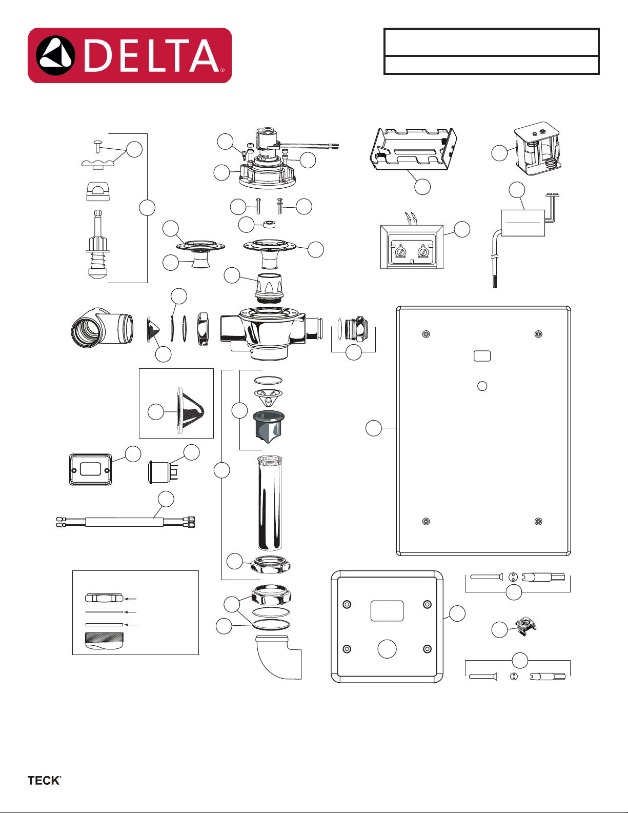
Electronic
after October 2014.
Concealed
Flushvalve
160__T6__ __ __A series
Write purchase model number here for future reference
13
14
Filter Screen
22
22
10c
10b
15
8b
8a
12
11a
16
11c
11b
9
10a
23
25
24
1
6
21
24VAC
6 VDC
2
3
5
Slip Joint Nut Installation
Nut
Fibre washer
Rubber washer
For valves manufactured
18
20
17
7
19
6
26
4
PLEASE LEAVE this M&I Sheet with the owner, maintenance plumber, etc as
items relating to ongoing maintenance suggestions and procedures are included.
213777, Rev. A
Page 2

Item # Part # Description
060799A Universal TECK washers and O-rings repair kit
061025A Universal TECK parts washers and O-rings repair kit
060704A٭
1
060771A٭
061273A ٭٭
2
061272A ٭٭
3 060679A Override button assembly
4 060072A No. 6 - 32 x 2” at head stainless steel screws (4/pkg) and security spanner bit package for 4-1/2“ (114 mm) cover
5 060680A 48” (1,220 mm) Solenoid Extension Wire
061244A
6
060674A
060675A
7 060073A No.10 - 32 x 2” at head stainless steel screws (4/pkg) and security spanner bit package for 14“ (356 mm) covers
8a 061024A Regulating screw and O-ring
061341A ٭٭
061342A ٭٭
8b
10a 061323A ٭٭٭ Diaphragm/Guide Assembly Complete - W/C (see Table 1)
10b 061324A ٭٭٭ Diaphragm Guide Assembly for Urinals (See Table 1)
10c 060079A-MMO Diaphragm only (12/pkg)
11a 060507A Poppet Pin Pack (3/pkg) (also see 11b) (See Table 1)
11b 060508A Poppet Pin Pack (3/pkg) (0.5L Valves only) (See Table 1)
11c 062025A Washer (3/pkg) (required for 6.0 & 4.8L Valves only) (See Table 1)
12 062007A ٭٭٭ Brass seat with O-ring
13 060479A Handle and screw
14 060845A Retro t check stem unit, capnut and handle complete
15 060082A Adjustable Tail O-Ring Package (20/pkg)
16 060785A Vacuum breaker sleeve complete
17 060094A Coupling ring
18
19
20
21 060683A ٭ 24VAC to 6VDC converter
22 060344A Filter screen kit (12/pkg)
23 060342A Plug and O-ring for handle end
24 060681A Flat battery holder (4 “C” cell batteries)
25 060684A Square battery holder (4 “C” cell batteries) - required for 4” (102 mm) box
26 060923A Nut retainers for access box frame (12/pkg)
061343A ٭٭
061344A ٭٭
061345A ٭٭
061346A ٭٭
061169A ٭٭
9 060078A Screws for Cast Cap (4/pkg)
060782A
060783A
060778A
060463A
060083A
060049A
Transformer (110 to 24 VAC) for 5 sensor modules
Transformer (110 to 24 VAC) for 10 sensor modules
Sensor module - urinal ush valve
Sensor module - water closet ush valve
4-1/2” x 4-1/2” (114 mm x 114 mm) (shown) stainless steel cover with studs and screws
14” x 14” (356 mm x 356 mm) (not shown) stainless steel cover with studs and screws
14” x 20” (356 mm x 508 mm) (shown) stainless steel cover with studs and screws
Cap/Solenoid & Regulating Screw Assembly for 0.5L (0.125 gal) xed urinals (see Table 1)
Cap/Solenoid & Regulating Screw Assembly for 1.9L (0.5 gal) xed urinals (see Table 1)
Cap/Solenoid & Regulating Screw Assembly for 4.2L (1.1 gal) xed water closets (see Table 1)
Cap/Solenoid & Regulating Screw Assembly for 4.8L (1.27 gal) xed water closets (see Table 1)
Cap/Solenoid & Regulating Screw Assembly for 6.0L (1.6 gal) xed water closets (see Table 1)
Cap/Solenoid & Regulating Screw Assembly for 1.9L (0.5 gal) adjustable urinals (see Table 1)
Cap/Solenoid & Regulating Screw Assembly for 6.0L (1.6 gal) adjustable water closets (see Table 1)
1-1/2” x 10” (38 mm x 254 mm) V.B., coupling ring and tube complete
1-1/2” x 22-3/4” (38 mm x 578 mm) V.B., coupling ring and tube complete
1½” Rough Coupling Nut & Washers
¾” Coupling Nut, ¾” Washers & ¾” Spud Flange
1½” Slip Joint Washers (12/pkg)
¾” (19mm) Rubber and ber washers (12/pkg)
NOTE: Refer to TECK ushometer repair parts and maintenance manual for additional parts and information.
٭ Each individual sensor module requires its own 24VAC to 6VDC hardwire converter.
٭٭ For valves manufactured before October 2014, you must replace both the sensor module and the cap/solenoid which are
included in; UR Kit - 061284A or WC Kit - 061285A.
٭٭٭ For valves manufactured before January 2013, you must replace the sensor module and the cap/solenoid, diaphragm assembly
and the brass seat with O-ring which are included in; UR Kit - 061286A or WC Kit - 061287A.
www. s p e c s e l e c t . c o m
Page 2
213777, Rev. A
Page 3

Table 1 - Cap/Pin/Diaphragm Confi guration Table
060508A
061324A
060507A
060507A &
061323A
Flush Volume
٭٭0.5L (0.125 gal)
Cap/Solenoid & Regulating Screw
(includes Cap, Solenoid, Regulating
Assembly
Screw)
061341A
Poppet Pin Diaphragm Assembly
٭UR - Fixed
UR - Adjustable
٭ W/C - Fixed
061342A
٭٭1.9L (0.5 gal)
061346A
1.9L (0.5 gal)
061343A
٭٭4.2L (1.1 gal)
061344A
٭٭4.8L (1.27 gal)
062025A
061345A
6.0L (1.6 gal)
061169A
W/C - Adjustable
NOTE: Must use all noted components listed in Table 1 to ensure correct fl ush volumes.
٭ Fixed models have epoxy in the adjustment screw.
٭٭ WaterSense
6.0L (1.6 gal)
®
compliant when paired with a WaterSense fi xture rated for the same fl ush volume.
www. s p e c s e l e c t . c o m
Page 3
213777, Rev. A
Page 4

BEFORE THE FIRST FLUSH
INSTALL FILTER SCREEN (included):
Note: Place lter in stop bore with conical screen facing the water ow.
Caution: Do not push lter in too far. Let lter seat against face of ush valve tail. Periodic cleaning of the lter screen with water is
recommended depending on local water conditions to remove any dirt or sediment. See lter screen M&I for additional installation
information.
FLUSH BOTH OLD AND NEW PIPES:
It is important to FLUSH and CLEAN thoroughly both old and new water piping to ELIMINATE contaminants (eg. scale, sediment, gravel,
cuttings, solder, etc.) from the line. Where the water has a sediment content, a PIPE STRAINER in the supply line should alleviate that
condition and protect working parts of ushometers and faucets. On a NEW INSTALLATION, always ush the valve 4 or 5 times to clean out
supply line debris. It is also advisable where more than one ushometer is installed on a water line, to ush out the water piping through the
last ushometer outlet of the pipe line.
ELIMINATE AIR FROM VALVES:
The FIRST FLUSH should ELIMINATE all air from the TECK ushometer.
DO NOT ADJUST ushometer based on the results of the rst ush.
TO PREVENT WATER HAMMER:
A capped-pipe vertical AIR CHAMBER may be installed at the last ushometer and/or at the back of an individual installation. This assures
SMOOTHER OPERATION of the valves and longer life for the working parts.
FLUSH VOLUME ADJUSTMENT:
1.60 U.S. gallons/6.0 litres for water closets
0.5 U.S. gallons/1.9 litres for urinal valves
The Regulating Screw (061024A, item #8a) may be adjusted according to job
conditions and xture installed, to the proper water volume to ush that particular xture
(except -6, -42, -48, -19 and -05 models which are not eld adjustable).
NOTE: 4.2, 4.8 and 6 litre water closets or washdown urinals may require the Inlet Stop
to be set at only one turn open.
For a SHORTER ush, turn Regulating Screw (061024A, item #8a) left (counter-
clockwise) and right (clockwise) for a LONGER ush (except -6, -42, -48, -19 and -05
models which are not eld adjustable).
Fig. 3
FLUSHVALVE
ADJUSTMENT
Adjustment Screw
RECOMMENDED WATER SUPPLY:
W/C - minimum owing pressure: 25 psi (172 kPa), minimum ow rate: 25 gpm (95 lpm)
UR - minimum owing pressure: 25 psi (172 kPa), minimum ow rate: 8 gpm (30 lpm)
www. s p e c s e l e c t . c o m
Page 4
213777, Rev. A
Page 5

ELECTRONIC FLUSH VALVE INSTALLATION INSTRUCTIONS
STEP 1 - ROUGH-IN FLUSH VALVE, FRAME
OR BOX
NOTE: Due to excess back pressure of low ow water
closets, outlet tubes must be braced to prevent tubes
from disconnecting.
• Install and attach ush valve to water supply as per Fig.1C.
4” Sensor Plate Models
If Hardwire Operated
• 102 mm (4”) box is supplied, remove suitable knockouts and insert
cable bushing as per Fig. 1A.
• Rough-in box for sensor location as per Fig. 1D.
Note: Solenoid extension cord supplied with the trim is 1,220 mm (48”)
long.
• Securely attach box to wall structure.
• Install CSA and/or UL approved Class 2 transformer or equivalent
in a convenient location or in a pipe chase. (Do NOT install the
transformer inside the control box.)
• Run suitable wire from 24VAC power source into box. Use wire which
complies with local electrical codes for 1 amp load. No.18 cable is
usually sucient.
• Attach supplied plasterguard as per Fig. 1B to ensure sensor mounting
holes are positioned correctly.
Fig. 1A
Fig. 1B
6mm
(1/4”) Min.
35mm
(1-3/4”) Max.
55mm
(2-5/32”)
102mm
(4”)
Plaster
Guard
Standard Electrical Box
102 x 102mm (4” x 4”)
Cable Bushing
Knockouts
Vandal Proof
Screws (4)
Small Sensor Box
Finished Wall
114mm
(4-1/2”)
Sensor
Stainless Steel Coverplate
114mm
(4-1/2”)
4” Sensor Plate Models
If Battery Operated
• 102 mm (4”) box and 4” box extension is supplied. Remove suitable
knockout as per Fig. 1A.
• Attach box extension to front of the box.
• Rough-in box assembly for sensor location as per Fig. 1D.
Note: Solenoid extension cord supplied with the trim is 1,220 mm (48”)
long.
• Securely attach box to wall structure.
• Attach supplied plasterguard as per Fig. 1B to ensure sensor mounting
holes are positioned correctly.
14” and 14” X 20” Sensor Plate Models
• 12” or 12” x 18” frame is supplied. Rough in frame so the valve will be
positioned as shown per Fig. 1D.
• Securely attach frame to wall structure.
Fig. 1C
305mm (12”)
Square
Access
Box Frame
Outlet Parts
Tubing, Elbow,
Wall and Spud
Flange, Spud
Nut, etc.
Supplied as
required for
Fixture specified.
Except for:
3/4” and 1-1/4” Top
Inlet Urinal Fixtures
where exposed
Tubing, Flanges,
Elbow, etc.
(Supplied by Others)
Flushvalve
Wheel
Handle
Stop
1” I.P. Inlet
121mm
(4-3/4”)
305mm
(12”) Square
www. s p e c s e l e c t . c o m
Page 5
213777, Rev. A
Page 6

Fig. 1D
BOF = Bottom Of Frame
356mm (14”)
305mm (12”)
Square Frame
Access
Box Frame
Flushvalve
Outlet Parts
Tubing, Elbow, Wall
and Spud Flange,
Spud Nut, etc.
Supplied as required
for Fixture specified.
Square
Stainless
Steel Cover
Sensor
of Sensor
Seat
Minimum
TOILET
76mm
(3”)
NOTE: Flushometer MUST be paired with a fixture of
equivalent flush volume.
4-1/2” square
stainless steel plate
(box 4” x 4”)
of
sensor
C
L
(Centerline)
Bottom of rough in box
to be 70mm (2.75”) below
centerline of sensor
* NOTE: Recommended height to sensor from top of fixture is 508-559 mm (20-22”)
with 610 mm (24”) maximum.
57mm
(2.25”)
to BOF
14” square
stainless steel plate
(frame 12” x 12”)
C
L
(Centerline)
Bottom of rough in box
to be 203mm (8”) below
centerline of sensor
stainless steel plate
frame
outline
of
sensor
76mm
(3”) to
BOF
(frame 12” x 18”)
Bottom of rough in box
to be 375mm (14.75”) below
centerline of sensor
14” x 20”
C
L
(Centerline)
of
sensor
248mm
(9.75”) to
BOF
NOTE: Due to excess back pressure of low flow water
closets, outlet tubes must be braced to prevent
tubes from disconnecting.
4-1/2” square
stainless steel plate
(box 4” x 4”)
Access
Box Frame
Flushvalve
Outlet Parts
Tubing, Elbow, Wall
and Spud Flange,
Spud Nut, etc.
Supplied as required
for Fixture specified.
(Except For 3/4” and
1-1/4” Top Inlet Urinal
Fixtures.)
305mm (12”) Square Frame
Sensor
of sensor
279mm
76mm (3”)
URINAL
(11”)
C
L
of
sensor
222mm
(8.75”)
to BOF
(Centerline)
BOF = Bottom Of Frame
14” square
stainless steel plate
(frame 12” x 12”)
76mm (3”) to BOF
of
sensor
frame
outline
C
L
(Centerline)
stainless steel plate
165mm
(6.5”)
14” x 20”
(frame 12” x 18”)
76mm (3”) to BOF
C
L
(Centerline)
of
sensor
Product Supplied as Shown by Solid Lines.
All Items Shown by Dotted Lines Supplied by Others.
www. s p e c s e l e c t . c o m
Page 6
213777, Rev. A
Page 7

STEP 2 - INSTALL SENSOR PLATE
If Hardwire Operated
• Attach hardwire converter supplied to the 24VAC power source using the wire
nuts provided.
• Attach converter to the sensor module using the snap connector. With power
to ushometer, there will be a sequence of red lights that strobe across the
sensing lens window which signies that the valve is now in operation mode.
• 4” Plate Models - Connect the female connectors from the sensor module to the solenoid ush valve. A 1,220 mm (48“) solenoid
extension cord has been provided, if required, to make the connection between the sensor module and solenoid. Make sure to correctly
match the wire colours on the sensor module to the solenoid.
• 14” Plate Models - Connect the female connectors from the sensor module to the solenoid on the ush valve. Make sure to correctly
match the wire colours on the sensor module to the solenoid.
• If the factory default settings for the sensor are not suitable, refer to step 4 for sensor adjustments.
• Attach sensor plate to the box using the 4 vandalproof screws provided.
Fig. 2
Sensor Extension Cord
If Battery Operated
• Install 4 “C” cell batteries provided into the battery holder and attach the holder to the sensor module using the battery clip. Use the +/on the battery holder for correct battery positioning. With power to ushometer, there will be a sequence of red lights that strobe across
the sensing lens window which signies that the valve is now in operation mode.
• 4” Plate Models - Connect the female connectors from the sensor module to the solenoid ush valve. A 1,220 mm (48“) solenoid
extension cord has been provided, if required, to make the connection between the sensor module and solenoid. Make sure to correctly
match the wire colours on the sensor module to the solenoid.
• 4” Plate Models - Install battery holder into the back of the box and attach the sensor plate to the box using the 4 vandalproof screw
provided.
• 14” Plate Models - Connect the female connectors from the sensor module to the solenoid on the ush valve. Make sure to correctly
match the wire colours on the sensor module to the solenoid.
• If the factory default settings for the sensor are not suitable, refer to step 4 for sensor adjustments.
• 14” Plate Models - Attach battery holder with the 2 way tape provided, to a secure location on the wall framing, etc.
STEP 3 - OPERATION MODE
A sequence of red lights that strobe across the sensing lens window will signify that the valve is now in operation mode.
Once in operation mode, if factory settings are preferred, no further action is required and the valve installation is complete.
Factory pre-set functions are:
Water closet sensing distance of 40” and ush delay is 4 seconds.
Urinal sensing distance of 20”, 24 hour ush is o, and no ush delay.
Once in operation mode, if adjustments are preferred, installer must move into set up mode.
FUNCTION AND TROUBLESHOOTING LIGHTS
BATTERY VERSION: NO LIGHTS-NO POWER
Check that the 4 “C” batteries are positioned properly in the battery holder. Use the +/- on the battery holder for correct positioning. If the
batteries are positioned correctly but there are still no lights, replace with 4 new “C” Alkaline batteries.*
HARDWIRE VERSION: NO LIGHTS-NO POWER
Check that the 24VAC transformer has power on the incoming 120VAC side. (Transformer breaker is turned on.)
Check the connection of the ushometer wires to 24VAC transformer.
Check that the connection of the hardwire converter is made to the electronic board within the electronic ush valve housing.
For further technical assistance, call Delta Commercial Technical Service at 1-800-387-8277 (Canada) or 1-877-509-2680 (U.S.A.).
1. Start-Up: When the system is rst powered, a sequence of red lights that strobe across the sensing lens window will signify that the
valve is now in operation mode.
2. Override Button in Operating Mode: BLUE light ashes once when Override Button is activated. Should the manual override button
stick, the program will continue to operate and will reset automatically if the override button is repaired or it returns to home position.
3. Battery Level Indicator: RED light ashes every 3 seconds, indicating approximately 5,000 ushes remain from when RED light rst
started ashing.
4. Checking Battery Strength: In operation mode, it is possible to check the strength of the batteries by holding down the override
button until the RED lights begin to ash. The strength of the batteries is proportional to the number of lights that are displayed when
the override button is held down. For example, 5 RED lights signify full battery strength; while 1 RED light indicates very weak battery
strength (replace batteries when this occurs).
* Note: All original settings will be retained when batteries are changed.
www. s p e c s e l e c t . c o m
Page 7
213777, Rev. A
Page 8

STEP 4 - MAKING ADJUSTMENTS
(Optional: Only required if factory settings are not preferred.)
• To move from operation mode into set-up mode: remove the plastic plug located in the rear of the sensor module and press the set-up
mode button once. A pencil or small screwdriver may be required. When done, place the plug back in the hole.
4.1 Adjusting Sensing Distances:
• Sequences of red lights will intermittently strobe across the sensor window, followed by a number of red lights which stay on to indicate
the current sensing distance.
Pre-set sensing distances are:
Water Closet Urinal
1 light 24” 1 light 12”
2 lights 32” 2 lights 16”
3 lights 40” (factory set) 3 lights 20” (factory set)
4 lights 48” 4 lights 24”
5 lights 56” 5 lights 28”
• A pulsating blue light on the far left of the sensor window will indicate if an object is detected. However, the sensing distance could be
set at a distance greater or shorter than the desired activating position.
• To ensure sensing distance is set to precise desired position, stand at desired activating distance.
• If the pulsating blue light is not present, press the override button (the red lights will increment).
• Continuing to press the override button will eventually loop the sensing distance back to 1 light (12” sensing distance for urinal, 24”
sensing distance for water closet).
• Press override button until pulsating blue light is present. The blue light indicates that the sensing distance has been adjusted to a
position that is detecting you.
Water closet only:
• Now stand back and ensure that the pulsating blue light disappears when you stand near the door of the water closet.
• Ensure that the door is not being detected as well. If so, decrease the range increment by 1 light (this is achieved by pressing the
override button until the lights loop back around to a setting that is one less the previous setting).
• Once again, verify that the sensor is not detecting the water closet door. If not, the sensor is now set at your desired position.
• The sensing distance for water closets can be set between 24” and 56”, and for urinals between 12” and 28”.
• If all adjustments have been completed, press and hold down the manual override button for 5 seconds. For water closets; this will
return the valve to operation mode. For urinals; this will advance the distance adjustment mode into the 24 Hour Flush adjustment
mode.
4.2 Adjusting 24 Hour Flush (for Urinal applications):
• When 3 red lights in the centre of the sensor window are on, 24 hour ush is on.
• When the red light in the middle of the 3 lights is o, the 24 hour ush is o.
• Press manual override button to toggle between on and o mode.
• If all adjustments have been completed, press and hold down the manual override button for 5 seconds until all lights go out.
www. s p e c s e l e c t . c o m
Page 8
213777, Rev. A
Page 9

PROBLEM SOLVING & MAINTENANCE SUGGESTIONS
NOTE: DO NOT USE EXCESSIVE FORCE to close the inlet stop stem. We RECOMMEND that the ushometer be ushed while closing
the inlet stop. The noise created by the water ow or the ow into the xture will stop when the inlet water is shut o.
NOTE: Always use DELTA COMMERCIAL GENUINE PARTS to maintain the warranty.
EXCESSIVE NOISE:
1. PARTIALLY close the inlet stop.
2. Pressures OVER 75 PSI may lead to an increase in NOISE, water could SPLASH out of the xture more easily and the LIFE of any
plumbing valve may be SHORTENED.
3. INSTALL a Pressure Reducing Valve set at a lower pressure if actual pressure is over 75 PSI. While the TECK Flushometer will operate
up to 125 PSI, the preferred operating range is between 35 to 65 PSI.
4. On ushometers that have been installed for a number of years, check the Renewable Seat (062007A, item #12) for wear and replace if
necessary.
EXCESSIVE WATER FLOW RATE:
1. OPEN inlet stop ONE TURN and adjust Regulating Screw (061024A, item #8a) to the xture requirement (except on -6, -19, -05, -42
and -48 models which are xed volume).
2. Operation of ushometer with inlet stop BELOW ONE TURN OPEN may cause EXCESSIVE NOISE. The lowest open setting for the
inlet stop may vary dependent on the installation.
SHORTAGE OF WATER TO PROPERLY FLUSH BOWL:
1. OPEN inlet stop fully.
2. CHECK pipeline for size or obstruction, partially closed gate or other supply line valve, corroded or undersize water piping.
3. CHECK water pressure.
4. Water ow rate is determined by BOTH the water pipe size AND the water pressure available.
5. A water closet ush valve requires a minimum water supply of 1” (or larger), depending on a number of dierent factors including water
pressure (PSI) available, pipe size and length of pipe run, number of xtures per washroom and per building, xture type, xture usage
factor, elevation of valve above the water main, etc. We strongly recommend that pipe size calculations be done to insure proper water
supply sizes.
Flushometers DO NOT provide a water supply; they are merely automatically timed self-closing valves. The inlet supply piping is the water
reservoir that must supply sucient water volume in a short period of time (4 to 10 seconds) to properly ush and clear the xture.
CONTINUOUS FLUSHING:
1. The Regulating Screw (061024A, item #8a) may be turned RIGHT (clockwise) TOO FAR. Adjust by slowly turning the Regulating Screw
LEFT (counter-clockwise) (except -6, -19, -05, -42 and -48 models which are xed volume).
2. If ush is still continous, close inlet stop, remove Regulating Screw (061024A, item #8a), CLEAN bypass slot in the Screw, REPLACE it
in the valve and ADJUST slowly for proper ush (except -6, -42, -48, -19 and -05 models which are xed volume).
3. Remove cast cap assembly (item #8b) and Diaphragm/Guide Assembly (061323A - WC item #10a or 061324A - UR, item #10b) and
check for contaminants at renewable seat (item #12) and diaphragm and check for debris in the cap for blockage. Also CHECK that the
Diaphragm/Guide slides easily in the Renewable Seat.
VALVE WILL NOT FLUSH:
1. When the valve has been taken apart for servicing and re-assembled and does NOT operate, check that the Cast Cap has been put on
the body properly. The Regulating Screw (061024A, item #8a) should always be on the same side as the inlet stop.
2. When all lights operate as expected but valve will not ush, check that the solenoid makes a clicking sound. If no clicking sound is
present, then replace with Cap Assembly (item #8b).
3. After a number of years, the valve will ush but shuts o immediately when activated. The Diaphragm (060079A-MMO, item #10c) is
worn or split and needs replacing.
SLIGHT WATER LEAK INTO FIXTURE:
1. EXAMINE the seating surface of the Diaphragm (060079A-MMO item #10c) for imbedded sediment.
CLEANING INSTRUCTIONS
CLEAN the outside of the chrome plated ushometer with a damp cloth.
CAUTION: MOST Tub & Tile xture cleaners contain ACIDS. DO NOT WIPE the cloth used to clean ceramic xtures over the ushometer
as it will remove the chrome plating and leave a discoloured surface.
www. s p e c s e l e c t . c o m
Page 9
213777, Rev. A
Page 10

Limited Warranty on Delta® Commercial Products
Commercial products covered under this warranty include:
series, and
TO THE EXTENT PERMITTED BY LAW, ANY IMPLIED WARRANTY
OR CONDITION, INCLUDING THE IMPLIED WARRANTIES OF
MERCHANTABILITY AND OF FITNESS FOR A PARTICULAR PURPOSE,
WARRANTY, WHICHEVER IS SHORTER. Some states/provinces do not
allow limitations on how long an implied warranty or condition lasts, so the
INCIDENTAL OR CONSEQUENTIAL DAMAGES (INCLUDING LABOR
CHARGES TO REPAIR, REPLACE, INSTALL OR REMOVE THIS
PRODUCT), WHETHER ARISING OUT OF BREACH OF ANY EXPRESS
OR IMPLIED WARRANTY OR CONDITION, BREACH OF CONTRACT,
TORT, OR OTHERWISE. MASCO CANADA LIMITED SHALL NOT
BE LIABLE FOR ANY DAMAGE TO THE COMMERCIAL PRODUCT
NEGLECT, CHANGING BUILDING CONDITIONS (SUCH AS VOLTAGE
SPIKES), AGGRESSIVE WATERS FOR STERILIZATION, GRAY WATER
OR INCORRECTLY PERFORMED INSTALLATION, MAINTENANCE OR
REPAIR, INCLUDING FAILURE TO FOLLOW THE APPLICABLE CARE
AND CLEANING INSTRUCTIONS, AND ANY OTHER EXCLUSIONS SET
PARTICULAR PRODUCT. Some states/provinces do not allow the exclusion
or limitation of special, incidental or consequential damages, so the above
limitations and exclusions may not apply to you. Note to residents of the State
of New Jersey: The provisions of this document are intended to apply to the
This warranty gives you specific legal rights, and you may also have other
This is Masco Canada Limited’s exclusive written warranty and the warranty
If you have any questions or concerns regarding our warranty, please call, mail
This equipment has been tested and found to comply with the limits for a Class A digital device, pursuant to Part 15 of the FCC Rules. These limits
are designed to provide reasonable protection against harmful interference when the equipment is operated in a commercial environment. This equipment
generates, uses, and can radiate radio frequency energy and, if not installed and used in accordance with the instruction manual, may cause harmful
interference to radio communications. Operation of this equipment in a residential area is likely to cause harmful interference in which case the user will
Parts and Finish
All parts (including electronic parts other than batteries) and finishes of this
Delta® commercial product are warranted to the original purchaser to be free
from defects in material and workmanship for five (5) years from the date of
purchase. No warranty is provided on batteries. Special terms and conditions
may apply for specific models. Please refer to the model-specific Maintenance
and Installation manual for more details.
What We Will Do
Masco Canada Limited will repair or replace, free of charge, during the
applicable warranty period (as described above), any part or finish that proves
defective in material and/or workmanship under normal installation, use and
service. If repair or replacement is not practical, Masco Canada Limited may
elect to refund the purchase price in exchange for the return of the product.
These are your exclusive remedies.
What Is Not Covered
Any labor charges incurred by the purchaser to repair, replace, install or
remove this product are not covered by this warranty. Masco Canada Limited
shall not be liable for any damage to the commercial product resulting
from reasonable wear and tear, misuse, abuse, neglect, changing building
conditions (such as voltage spikes), aggressive waters for sterilization, gray
water (recycled or repurposed water for toilet usage), improper or incorrectly
performed installation, maintenance or repair, including failure to follow the
applicable care and cleaning instructions, and any other exclusions set forth
in the Maintenance and Installation manual for the particular product. Masco
Canada Limited recommends using a professional plumber for all installation
and repair. We also recommend that you use only genuine Delta® replacement
parts.
What You Must Do To Obtain Warranty Service Or Replacement Parts
A warranty claim may be made and replacement parts may be obtained by
calling or writing as follows:
In the United States and Mexico:
Delta Faucet Company
Product Service
55 E. 111th Street
Indianapolis, IN 46280
customerservice@deltafaucet.com
1 800 345 DELTA (3358)
In Canada:
Masco Canada Limited
Technical Service Centre
350 South Edgeware Road
St. Thomas, Ontario N5P 4L1
customerservice@mascocanada.com
1 800 567 3300
®
Delta
Delta Commercial TECK® series, Delta Commercial HDF
®
Delta Commercial DEMDTM series. This warranty applies only to Delta®
Commercial products installed in the United States of America and Canada.
Limitation on Duration of Implied Warranties
IS LIMITED TO THE STATUTORY PERIOD OR THE DURATION OF THIS
above limitation may not apply to you.
Limitation of Special, Incidental or Consequential Damages
MASCO CANADA LIMITED SHALL NOT BE LIABLE FOR ANY SPECIAL,
RESULTING FROM REASONABLE WEAR AND TEAR, MISUSE, ABUSE,
(RECYCLED OR REPURPOSED WATER FOR TOILET USAGE), IMPROPER
FORTH IN THE MAINTENANCE AND INSTRUCTION MANUAL FOR THE
fullest extent permitted by the laws of the State of New Jersey.
Additional Rights
rights which vary from state/province to state/province.
is not transferable.
or email us as provided above.
This device complies with Part 15 of the FCC Rules. Operation is subject to the following two conditions:
(1) this device may not cause harmful interference, and
(2) this device must accept any interference received, including interference that may cause undesired operation.
be required to correct the interference at his own expense.
W
Changes or modifications not expressly approved by the manufacturer could void the user’s authority to operate the equipment.
CAN ICES-3 (A) / NMB-3(A)
For further technical assistance, call Delta Commercial Technical Service at 1-800-387-8277 (Canada) or 1-877-509-2680 (U.S.A.).
©
2018 Masco Canada Ltd.
www.deltacommercialfaucets.com
213777, Rev. APage 10
 Loading...