


Topo USA User Guide


Table of Contents
Getting Started ........................................................................................................ 1
Welcome to DeLorme Topo North America ................................................................ 1
Frequently Asked Questions .................................................................................... 2
How do I? ............................................................................................................ 7
Basic Functions ..................................................................................................... 9
Running DeLorme Topo North America ..................................................................... 9
Zooming In and Out .............................................................................................. 9
Panning/Centering the Map ................................................................................... 11
Copying Your Map to the Clipboard ........................................................................ 12
Saving a Map as a Bitmap or JPEG Image ............................................................... 12
Measuring Distance and Area ................................................................................ 14
Chart of Supported Coordinate Formats .................................................................. 15
Searching Tips .................................................................................................... 17
Exiting the Program ............................................................................................. 18
About the Interface ............................................................................................. 19
Tab Area ............................................................................................................ 19
Control Panel ...................................................................................................... 19
Overview Map ..................................................................................................... 20
Toolbar .............................................................................................................. 21
Using the Help System ......................................................................................... 21
Help Overview .................................................................................................... 21
Using the Help System ......................................................................................... 23
Help Documentation Conventions .......................................................................... 25
Glossary Terms ................................................................................................... 26
Recreational Contacts .......................................................................................... 33
Map Legend ........................................................................................................ 43
iii

Topo USA User Guide
Using the Toolbar ................................................................................................... 49
Showing/Hiding Toolbar Options ............................................................................ 49
Reordering the Toolbar Options ............................................................................. 49
To Create a New Project ....................................................................................... 49
To Open a Project ............................................................................................... 49
To Save a Project ................................................................................................ 50
To Open the Map Library ...................................................................................... 50
To Share Maps .................................................................................................... 50
To Create a Route ............................................................................................... 50
To Sync Files and Information with a Handheld GPS Device ....................................... 52
To Measure Distance ............................................................................................ 52
To Get Information About a Location ...................................................................... 52
To Create a Profile ............................................................................................... 53
To Add Images and Data to a GPS Location ............................................................. 54
To Choose Options .............................................................................................. 54
To Grab and Pan the Map ..................................................................................... 55
To Start/Stop Your GPS Connection ....................................................................... 55
To Use GPS NavMode ........................................................................................... 56
To Print ............................................................................................................. 56
To Print the Map Screen ....................................................................................... 57
Customizing the Map and Tab Display ....................................................................... 59
Display Options Overview ..................................................................................... 59
Customizing the Interface ..................................................................................... 59
Displaying Basic Map Features .............................................................................. 60
Customizing the Map Feature Preferences ............................................................... 63
Changing the Map Colors ...................................................................................... 65
Showing Hybrid Maps .......................................................................................... 65
Changing the Map Magnification Level .................................................................... 66
iv

Table of Contents
Changing the Contour Details Preferences ............................................................... 66
Changing How POIs Display on the Map .................................................................. 67
Setting Units of Measure Preferences ..................................................................... 68
Resizing the Map and Tab Areas ............................................................................ 71
Viewing Two Maps at the Same Time ..................................................................... 73
Showing or Hiding Tabs ........................................................................................ 75
Importing/Exporting Tab Manager Preferences ........................................................ 76
Reordering the Tabs ............................................................................................ 77
Using Keyboard Shortcuts ....................................................................................... 79
Selecting a Keyboard Shortcut Scheme .................................................................. 79
Creating a New Custom Scheme ............................................................................ 79
Assigning Keyboard Shortcuts in a Custom Scheme .................................................. 80
Customizing a DeLorme Scheme ........................................................................... 82
Renaming a Custom Scheme ................................................................................ 82
Deleting a Custom Scheme ................................................................................... 83
Importing a Custom Scheme ................................................................................. 83
Exporting a Custom Scheme ................................................................................. 84
Searching For Commands ..................................................................................... 84
Viewing All of the Shortcut Keys for a Scheme ......................................................... 85
Viewing Map Data .................................................................................................. 87
Saving Data to Your Hard Drive ............................................................................. 87
Connecting Data ................................................................................................. 87
Viewing Data ...................................................................................................... 87
Using Projects and Map Files .................................................................................... 89
Projects and Map Files Overview ............................................................................ 89
Creating and Deleting Projects .............................................................................. 89
Opening an Existing Project .................................................................................. 90
Editing a Project .................................................................................................. 91
v

Topo USA User Guide
Saving a Project .................................................................................................. 92
Creating Transfer Files ......................................................................................... 92
Importing Transfer Files ....................................................................................... 94
Emailing a Transfer File ........................................................................................ 95
Finding a Location on the Map .................................................................................. 97
Find Options ....................................................................................................... 97
Find Overview ..................................................................................................... 98
Performing a Basic Search .................................................................................... 98
Performing an Advanced Search ........................................................................... 100
Performing a POI Search ..................................................................................... 103
Finding Points of Interest Near Your Current Location .............................................. 104
Tutorial: Find Points of Interest on a Route ............................................................ 106
Finding a Symbol by its Name .............................................................................. 108
Tips on Viewing Search Results ............................................................................ 109
Keywords for Category Searches .......................................................................... 110
MapTags: Converting, Moving, Hiding, and Deleting ................................................ 114
Using Address Book Contacts .................................................................................. 117
Searching for Address Book Contacts .................................................................... 117
Importing Existing Address Book Information ......................................................... 117
Manually Entering Address Book Information .......................................................... 118
Centering the Map on an Address Book Contact ...................................................... 119
Editing a Contact In Your Address Book ................................................................. 120
Manually Moving a Contact on the Map .................................................................. 120
Relocating Address Book Contacts ........................................................................ 121
Deleting a Contact In Your Address Book ............................................................... 121
Showing/Hiding Address Book Contacts on the Map ................................................. 122
Deleting Your Entire Address Book ........................................................................ 123
Exporting Your Address Book ............................................................................... 123
vi

Table of Contents
Printing ............................................................................................................... 125
Printing a Map ................................................................................................... 125
Printing a Route and Directions ............................................................................ 126
Printing a Profile ................................................................................................ 128
Adding Text or Graphics to Your Map .................................................................... 129
Aligning Text and Graphic Items on Your Map ......................................................... 132
Snapping Text and Graphic Items on Your Map ....................................................... 133
Layering Multiple Text and Graphic Items on a Printed Map ...................................... 134
Changing the Background Color of a Printed Map .................................................... 135
Manually Assembling a Multi-page Map .................................................................. 135
Using the Draw Tools ............................................................................................. 141
Draw Overview .................................................................................................. 141
Viewing Hidden Draw Tools .................................................................................. 146
Draw File Management ........................................................................................ 146
Creating a New Draw File .................................................................................... 146
Saving a Draw File ............................................................................................. 147
Deleting a Draw File ........................................................................................... 148
Hiding Draw Files ............................................................................................... 148
Editing/Locking Draw Files ................................................................................... 149
Exporting Draw Files to Text Files ......................................................................... 149
Exporting Track Data Files to Text Files ................................................................. 150
Exporting Track or Waypoint Files to GPX Files ....................................................... 151
Importing Files to Draw Files ................................................................................ 151
Formatting a Text File to Import as a Draw File ...................................................... 154
Copying a Map Line to a Draw File ........................................................................ 156
Saving a Track as a GPS Log ................................................................................ 156
Viewing the Contents of a Draw File ...................................................................... 157
Copying a Draw File ............................................................................................ 159
vii

Topo USA User Guide
Changing Draw Object Types ............................................................................... 159
Renaming a Draw File ......................................................................................... 161
Creating a Direct Route from a Line Object ............................................................ 161
Copying a Draw Object From One Draw File to Another ............................................ 161
Moving a Draw Object to a Different Draw File ........................................................ 162
Using Draw Objects ............................................................................................ 163
Copying and Placing Draw Objects ........................................................................ 163
Moving Draw Objects .......................................................................................... 164
Renaming a Draw Object ..................................................................................... 165
Deleting Draw Objects ........................................................................................ 166
Snapping Draw Objects ....................................................................................... 168
Adding Points to Draw Objects ............................................................................. 169
Deleting Points and Line Segments from Draw Objects ............................................ 170
Labeling a Draw Object ....................................................................................... 170
Routable Roads, Trails, Tracks, Lines, Arcs , and Splines .......................................... 171
Drawing Routable Roads or Trails on the Map ......................................................... 171
Drawing a Line, Arc, or Spline on the Map .............................................................. 172
Drawing a Track on the Map ................................................................................ 174
Tutorial: Convert Tracks into Trails ....................................................................... 175
Editing a Routable Road, Routable Trail, Line, Arc, or Spline ..................................... 177
Editing a Track ................................................................................................... 178
Placing a Routable Road, Routable Trail, Line, Arc, or Spline at a Specific Location ....... 179
Joining and Breaking Linear Objects ...................................................................... 180
Circles, Rectangles, and Polygons ......................................................................... 181
Drawing a Circle, Rectangle, or Polygon on the Map ................................................ 181
Editing a Circle, Rectangle, or Polygon ................................................................... 182
Placing a Circle, Rectangle, or Polygon on the Map .................................................. 183
Waypoints, Symbols, MapNotes, Text Labels, and Images ........................................ 184
viii

Table of Contents
Adding a Waypoint, Symbol, MapNote, Text Label, or Image to the Map ..................... 184
Editing a Waypoint, Symbol, MapNote, Text Label, or Image .................................... 186
Placing a Waypoint, Symbol, Text Label, or Image at a Specific Location .................... 187
Moving and Deleting Draw MapNotes .................................................................... 188
Custom Symbols ................................................................................................ 189
Custom Symbols Overview .................................................................................. 189
Creating a New Symbol ....................................................................................... 190
GPS Device Custom Symbols ............................................................................... 191
Editing a Symbol ................................................................................................ 193
Finding a Custom Symbol .................................................................................... 194
Importing a Bitmap ............................................................................................ 195
Copying and Pasting ........................................................................................... 196
Pasting a Bitmap into XSym ................................................................................. 197
Dragging a Bitmap into XSym .............................................................................. 198
Removing a Symbol ............................................................................................ 199
Draw Tool Box ................................................................................................... 200
Using the Transparency Option ............................................................................. 201
Anchor Position .................................................................................................. 201
Cursor Position .................................................................................................. 202
Creating a New Symbol Set ................................................................................. 203
Opening a Symbol Set ........................................................................................ 203
Routing ............................................................................................................... 205
Creating a Route ................................................................................................ 205
Tutorial: Create a Route ...................................................................................... 207
Adding and Inserting Stops and Vias ..................................................................... 209
Changing the Routing Method .............................................................................. 212
Changing the Properties of a Stop Along Your Route ................................................ 213
Viewing Route Directions ..................................................................................... 213
ix

Topo USA User Guide
Avoiding a Specified Area When Routing ................................................................ 214
Saving Route Directions as Text ........................................................................... 215
Setting Your Routing Preferences .......................................................................... 216
Editing a Route .................................................................................................. 217
Editing Roads .................................................................................................... 219
Labeling a Route Point with a MapNote .................................................................. 219
Moving Route MapNotes ...................................................................................... 220
Displaying and Centering Routes on the Map .......................................................... 220
Saving a Route .................................................................................................. 221
Deleting a Route ................................................................................................ 222
Importing Routes ............................................................................................... 222
Tutorial: Plan a Long Distance Trip........................................................................ 222
Setting Your End of Day and Fuel Break Preferences................................................ 226
Estimating the Fuel Cost of Your Route .................................................................. 227
Converting a Route to a GPS Log .......................................................................... 227
Using GPS ............................................................................................................ 229
GPS Overview .................................................................................................... 229
GPS Options/Initializing GPS ................................................................................ 229
Using NavMode or Tab View ................................................................................. 233
Tutorial: Route with GPS—NavMode ...................................................................... 235
Tutorial: Route with GPS—Tab View ...................................................................... 239
Tracking a Route with GPS .................................................................................. 241
Getting Back on Track When Off Course ................................................................ 242
Panning the Map Automatically While GPS Tracking ................................................. 242
Playing Back a Log File ........................................................................................ 243
Previewing a GPS Log File .................................................................................... 244
Viewing File Details for a GPS Log ......................................................................... 245
Monitoring Your GPS Status ................................................................................. 246
x

Table of Contents
Monitoring GPS Satellite Information ..................................................................... 247
Viewing Sun and Moon Information ....................................................................... 249
About GPS ........................................................................................................ 249
Using Voice Navigation .......................................................................................... 253
Voice Overview .................................................................................................. 253
Activating and Monitoring Speech Recognition ........................................................ 254
Voice Commands ............................................................................................... 255
Voice Prompts ................................................................................................... 259
Voice Options .................................................................................................... 259
Voice Options .................................................................................................... 260
Training the Speech Recognition Engine ................................................................ 260
Speech Recognition Tips ...................................................................................... 261
Changing Voice Output ....................................................................................... 263
Voice Preferences ............................................................................................... 264
Geocaching .......................................................................................................... 267
Geocaching Menu ............................................................................................... 267
Geocaching Overview .......................................................................................... 268
Managing Pocket Queries .................................................................................... 269
Using Earthmate PN-Series GPS Devices .................................................................. 271
PN-Series GPS Overview ..................................................................................... 271
Syncing Maps and Data ....................................................................................... 271
Sync Overview ................................................................................................... 271
Syncing Maps, Points, Routes, and Tracks .............................................................. 272
Tutorial: Add a Map to an Earthmate PN-Series GPS ................................................ 274
Tutorial: Sync Data with a PN-Series GPS .............................................................. 278
Deleting Files from a PN-Series GPS ...................................................................... 282
Sync Options ..................................................................................................... 282
Firmware Updates .............................................................................................. 283
xi

Topo USA User Guide
Creating Custom Map Packages ............................................................................ 284
Creating a Custom Map Package ........................................................................... 284
Grid Size Comparisons ........................................................................................ 287
Data Zoom Level/Scale Bar Translation ................................................................. 288
Using Third-party GPS Devices ................................................................................ 291
Sending Route Information .................................................................................. 291
Sending Tracks .................................................................................................. 292
Sending Waypoints ............................................................................................. 293
Receiving a Route .............................................................................................. 294
Receiving a Track ............................................................................................... 295
Receiving Waypoints ........................................................................................... 296
Using Small-screen Devices .................................................................................... 299
Using Small-screen Devices ................................................................................. 299
Profiling Linear Objects .......................................................................................... 301
Creating a Profile ............................................................................................... 301
Viewing the Profile Elevation Graphs ..................................................................... 302
Statistical Data .................................................................................................. 305
Manually Setting Minimum and Maximum Elevation ................................................. 308
Clearing a Profile ................................................................................................ 308
User Profile Data ................................................................................................ 309
Viewing Your Map in 3-D ........................................................................................ 313
Viewing a 3-D Map ............................................................................................. 313
Setting Your 3-D Map Preferences ........................................................................ 315
Flying Over a 3-D Map ........................................................................................ 316
Tutorial: Fly in 3-D ............................................................................................. 317
Using NetLink and MapShare .................................................................................. 321
NetLink Overview ............................................................................................... 321
Tutorial: Share Maps .......................................................................................... 321
xii

Table of Contents
Using GeoTagger .................................................................................................. 327
Getting Started with GeoTagger ........................................................................... 327
Tagging an Image .............................................................................................. 327
Tagging Data ..................................................................................................... 329
Calculate the Timestamp Offset ............................................................................ 330
Legal Information ................................................................................................. 333
DeLorme Topo North America 10.0 Single-User License Agreement ........................... 333
Important Notices .............................................................................................. 338
Apache License, Version 2.0 ................................................................................ 345
Index .................................................................................................................. 351
xiii


Getting Started
Welcome to DeLorme Topo North America
Helpful Links
• DeLorme—product information and more
• Technical Support—searchable knowledge base, articles, troubleshooting
• Community Forums—a wealth of information from the people who use our
products
• DeLorme Weblog—announcements, tips and tricks, and tutorials
What's New
• Updated road and trail data in the US and Canada including more than 800,000 new
road names in the US.
• Updated with hi-detail lake, river and stream data for all 50 states.
• Includes elevation data for all of Mexico and updated elevation data for Alaska.
• Now includes park data in Canada, 38 National Parks and 100 popular Provincial
Parks.
DeLorme Topo North America Features
These are just some of the many features that you can enjoy with DeLorme Topo North
America:
• Try our data downloads for free! Included with your purchase is a download
certificate for $40 worth of data and imagery using the NetLink tab
required). You can also subscribe to the DeLorme Map Library and get unlimited
downloads for an annual fee of only $29.95.
• Use the Handheld Export tab to create custom maps to send to your Earthmate PN-
Series GPS.
• Search for trails, state parks, mountain peaks, unique natural features, points of
interest, and more.
(registration
• View your maps in 3-D and fly over the terrain with shaded relief, detailed land
use/land cover features, and elevation contours.
• Use the split-screen functionality to view two types of data for the same location at
the same time.
1

Topo USA User Guide
• Create trail, road, or direct routes
Customize your route by adding stops and vias.
• Use the toolbar to share maps, add data and images to the map, open/create/save
projects, start/stop GPS, edit your preferences, and more.
• Profile map items and objects you draw/add to the map to determin e c o or d inate
information, linear distance, elevation, grade, and so on.
• Print high quality, detailed, 2-D or 3-D single-page maps, and/or mural maps as
large as 3 x 3 pages. You can even print routes, route directions, and profiles.
• Create custom keyboard shortcuts or select a DeLorme shortcut scheme, such as 3-D
Navigation, to navigate the program more easily than ever.
• Connect your GPS device to the program and track your progress on a laptop as you
travel.
• And much more!
by adding start and finish points on your map.
Frequently Asked Questions
These questions are asked most frequently by our customers.
Click a question to reveal its answer. To hide the answer, click the question again.
• How do I get maps from DeLorme Topo North America to my Earthmate PN-Series
GPS device?
To get started, see these tutorials:
Tutorial: Add a Map to Your PN-Series GPS
Tutorial: Sync Data with a PN-Series GPS
To learn how to make a custom map, see Creating a Custom Map Package.
For more information, see the PN-Series GPS Help topics under Using Earthmate PN-
Series GPS Devices.
• Is my GPS device supported?
DeLorme software works with different types of GPS devices.
• DeLorme Earthmate GPS Handheld Devices—DeLorme Topo North
America 10.0 supports DeLorme Earthmate PN-30 and higher models.
2
• DeLorme Earthmate GPS Laptop Devices—LT-40 (and previous versions)
and BT-20 for laptops.

• USB GPS Support—DeLorme software can use the data output from a USB
GPS if the device meets one of the following criteria:
• When the GPS is attached to the computer, it is recognized and
displayed under Ports in the Microsoft® Windows® Device Manager.
• The unit is a Garmin USB device and the Garmin drivers are installed.
Note Magellan USB devices are not currently supported.
• Serial GPS Support—DeLorme software can use the data output from a
serial GPS device. The device must be connected to a free COM port and
output a generic NMEA (National Marine Electronics Association) stream.
• Bluetooth GPS Support—DeLorme software can use the data output from a
Bluetooth GPS device. You must configure your Bluetooth software to create a
virtual serial port.
• How do I find a specific location?
Getting Started
Use DeLorme Topo North America's search tools to locate places and points of
interest (POIs) in the United States and Canada and places in Mexico.
In addition, you can search for places along your route, within a certain radius of the
current map center, or within a particular region.
To access the search features in DeLorme Topo North America, click the Find tab.
For more information on searching for specific locations, see
Performing a Basic
Search, Finding Points of Interest Near Your Current Location, Performing a POI
Search, and Performing an Advanced Search.
• How can I find all of the nearby points of interest?
Right-click your loca tion on the map, click Find Travel POIs, and then click the
distance you want to search within (1 mile, 5 miles, or 10 miles). The points of
interest display in Find tab results area.
OR
If you are tracking with a GPS device, do a radar search
to locate points of interest
within a designated distance of your current GPS position.
• Where do I find the map settings and other Options settings?
Click the Options button on the toolbar to modify GPS, sync, voice, map
feature, display, keyboard shortcut, and 3-D preferences. For more information, see
To Choose Options
.
3

Topo USA User Guide
• How do I perform an Along the Way search in the Find tab and print my results?
Search for names or categories along your current route by performing an advanced
search in the Find tab. You can then print your search results using the Along the
Way print option.
Use the following steps to search for a name/category along your current route and
print the results:
•
1. Click the Find tab and then click Advanced. The Advanced dialog area
displays.
2. Select Category from the From drop-down list .
3. Select Current Route from the Within drop-down list.
4. Type the appropriate keyword in the Keywords text box.
5. Type the distance in the Distance text box.
6. Click Search.
The search results display in the dialog area.
7. Click the Print tab and then click Route. The Route dialog area displays.
8. Select the Along the Way check box.
9. Click Print Now.
The search results print.
• How do I submit a data update or fix the roads on my map?
•
• If you find there is a missing local road, you can add it to the current Draw
layer using the Routable Roads Draw tool. For more information, see Drawing
Routable Roads or Trails on the Map.
• To report an error to DeLorme:
•
1. Click the NetLink tab.
2. Click the Support subtab.
3. In the Map Corrections box, click the Submit Correction link.
4. Use the Customer Revisions wizard to submit the change.
• What is a project?
You can save all of your work as a single workspace so you can open it again later.
These saved workspaces are called projects.
4
A project is made up of the following items: coordinates of the map center, current
zoom level, current magnification, map display preferences, any added items: such
as draw layers, routes, and so on. As you create new routes or draw layers, change
Getting Started
preferences or the map center, and so on, they are added to the current project. You
can save or discard changes.
To learn how to create a project, see Creating and Deleting Projects
.
• What is the difference between a stop and a via?
When routing in DeLorme Topo North America, you have the option of
adding/inserting stops or vias
in the route. A stop is a location in a route where you
want to stop and then proceed from. A via is a location on the map that you want the
route to use.
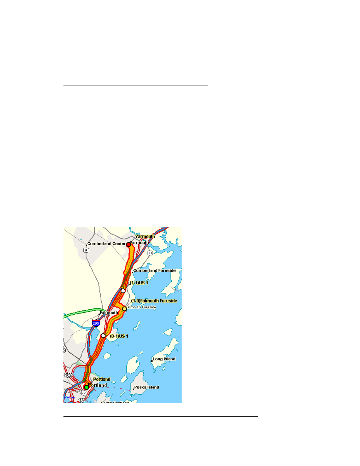
For example, if you create a route between Portland, Maine, and Yarmouth, Maine,
with no stops or vias, the r oute directions will tell y o u to take I-295. However, if you
want to take US Route 1 instead, you can place vias in the route on US Route 1 to
force the route to go by way of US Route 1. If you plan on stopping in Falmouth
Foreside for lunch, you will want your route directions to reflect that stop. When you
add a stop, you can recalculate to include it.
This map shows the area between Portland, Maine, and Yarmouth, Maine, with two
vias and one stop.
• What's the difference between adding and inserting a stop or via?
5

Topo USA User Guide
The Insert Stop/Via function arranges stops/vias geographically in the route.
The Add Stop/Via function adds stops/vias in the order you add them to the route.
For more information, see Adding and Inserting Stops and Vias
.
• Why did my route fail to calculate?
Your route will fail to calculate if you create a route:
•
• With a route start, stop, via, or finish point in an area that you have
designated as a Route Avoid
.
• That includes route points outside the United States. If you have the North
American version of DeLorme Topo North America, for routes that include
points outside of the United States, Canada, or Mexico.
• On an island without roads. In this case, DeLorme Topo North America looks
for the nearest road to that island to place the route point. If the nearest road
is not routable (for example, it is the only road on the island and/or the island
does not have ferry access), you will get an error message saying, "Route
failed to calculate."
• Why do X marks sometimes display on the map when I calculate a route?
• When you place a route point in a location that isn't on a street, DeLorme
Topo North America finds the closest street to that location, marks the space
between the point you clicked and the street with X marks, and starts the
route at the street.
• If you search for an address that is on a walkway and place a route point on
it, DeLorme Topo North America finds the closest street to that location,
marks the space between the point the clicked and the street with X marks,
and starts the route at the street.
• Why is the tab area and control panel so narrow?
DeLorme Topo North America was designed for resolutions of 800 x 600 or higher. If
you are using a very high resolution (such as 1920x 1200), the tab area and control
panel may appear to be very narrow. You can
modify the size of the map and tab
area or use the Windows® Control Panel to adjust your display settings.
• What's the best way to measure the distance of a road or trail?
6

Getting Started
The best way to determine the distance of a particular road or trail is to create a
route. You can create a route using right-click functionality, the too lbar, or the Route
tab. For more information, see Creating a Route
• What's the best way to measure a large area on the map?
The best way to measure a large area on the map is with the area tools on the Draw
tab (such as the polygon tool). When you draw an area object on the map, the area
displays next to the object on the map. If you click off the object, you can view the
area again by clicking the Select tool in the Draw tab and then clicking the area
object on the map. For more information about drawing area objects, see Drawing a
Circle, Rectangle, or Polygon on the Map.
• What's the best way to measure a short distance on the map?
The best way to measure a short distance (that is not made up of a road/trail) on the
map is to use the Measure tool on the toolbar. You can measure linear distance
and area on the map based on the units chosen in the Display tab of the Options
dialog box. For instructions on using the measure tool, see
Area.
• Why won't 3-D billboards display?
.
Measuring Distance and
If you receive a message saying that 3-D billboards cannot be displayed, ensure that
you have a 32 MB video card with the most recent drivers and that it supports
DirectX and transparencies.
How do I?
Click a question to open the related Help topic. See also, Frequently Asked Questions.
Controlling the Map
How do I pan the map?
How do I zoom the map in and out?
How do I change the map view to show the left map view, right map view, or both?
Display Preferences
How do I change the map colors?
Draw Tools
How do I add a road or trail to my map?
7

Topo USA User Guide
Earthmate PN-Series GPS
How do I use my mapping app lication with my PN-Series GPS?
Searching for a Location
How do I search for a location?
GPS
How do I start tracking with my GPS device?
Map Data
How do I work without the DVD?
How do I switch the data that displays in the left map windo w?
Map Files
What is a project?
Routing
How do I create a route?
How do I track a route with my GPS receiver?
How can I automatically recalculate my route when I'm off course?
How can I avoid a specific area when routing?
Printing
How do I print a map?
Profile
How do I view a profile of a route I've created?
1. Center the route you want to profile on the map.
2. Click the Profile tab.
3. Select a route on the map to generate its profile. When the object is selected, it is
highlighted and the Profile graph displays in the Profile dialog area.
3-D
How do I generate a 3-D map?
How can I expand my 3-D map to fit the entire screen?
8

Getting Started
Basic Functions
Running DeLorme Topo North America
After you install the program, you can run it with the DVD to use the data without installing
it to your computer's hard drive. For more information on installing data to your hard drive,
see Saving Data to Your Hard Drive
.
To Access Data from the DVD
Choose one of the following ways to access the data using the DVD.
• If you installed a desktop shortcut, insert a DeLorme Topo North America DVD into
your computer's DVD drive and then double-click the DeLorme Topo North
America 10.0 icon.
OR
• Insert a DeLorme Topo North America DVD into your DVD drive. Click Start, point to
Programs > DeLorme > Topo North America 10.0, and then click DeLorme
Topo North America 10.0.
Zooming In and Out
You can use the drag and zoom feature, zoom tools, or the data zoom level(Data zoom level
is the relationship between what you see in a map view and how it exists in reality. It is the
amount of geographic data displayed on a computer monitor. The data zoom level is similar
to the traditional fractional relationship expressed on paper maps. For example, 1:24,000,
1:100,000, 1:500,000, and so on.) to quickly change the zoom level of the map view.
Notes
• Increase the data zoom level number to show a smaller geographic area at greater
detail.
• Decrease the data zoom level number to show a larger geographic area at lesser
detail.
• If you view both the right (primary) and left (secondary) maps at different data
zoom levels, a box (or lines, depending on the current data zoom level) displays on
the map that is zoomed out the furthest. The box/lines indicate th e area that is in
view on the other map.
• If you view the right and left maps at the same data zoom level but they are not
equally represented on the screen (50/50), a box (or lines) displays on the map that
9
Topo USA User Guide
is covering the most screen area. The box/lines indicate the area that is in view on
the other map.
To Drag and Zoom In
Use the following steps to zoom in either the right or left map.
1. Click and hold down the left mouse button as you drag the mouse in a down-right
direction on the map to encompass the area you want to display. A view box displays
on the screen and changes dimension as you move the mouse. A label displays the
data zoom level at the current map center.
2. Once you reach the map area or data zoom level you want to display, release the
mouse button. The area you selected fills the map window, the map re-centers, and
the map view adjusts to show the appropriate level of detail.
Tip To move the view box to another location, press the SHIFT key at any time.
To Drag and Zoom Out
Use the following steps to zoom in either the right or left map.
1. Click and hold down the left mouse button as you drag the mouse in an up-left
direction on the map. A staircase with a small circle displays on the screen.
2. Continue dragging the mouse in an up-left direction. The small circle moves up the
steps, one step per data zoom level. A label displays the data zoom level to t he
bottom-right of the staircase.
3. Once you reach the data zoom level you want to display, release the mouse button.
The map view adjusts to display the appropriate level of detail. The map center is
retained on your screen.
To Zoom In/Out Using the Zoom Tools
There are two sets of zoom tools. The zoom tools for the right map are located in the
Control Panel
Right
. The zoom tools for the left map are located at the top of the left map view.
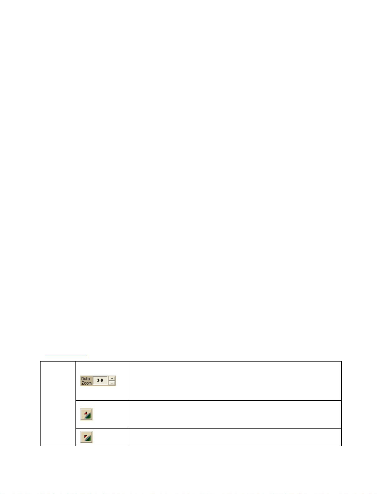
Click the up arrow to zoom out one minor data zoom level at a
time. Click the down arrow to zoom in one minor data zoom
level at a time.
Map
Controls
10
Click the Zoom In 1 tool to increase the detail number to the
next full level.
Click the Zoom Out 1 tool to decrease the detail number to t he
Getting Started
next full level.
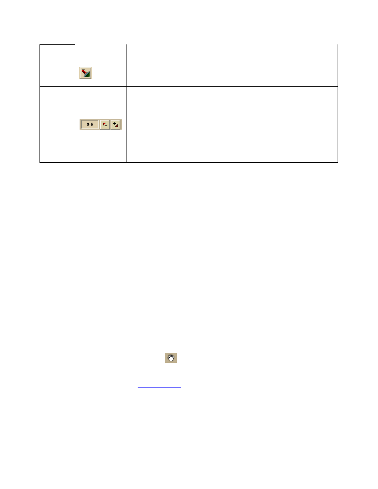
Click the Zoom Out 3 tool to decrease the detail number by
three full levels.
Click the plus button to increase the detail number to the next
full level.
Left
Click the minus button to decrease the detail number to the
Map
next full level.
Controls
The data zoom level of the left map displays in the text area to
the left of the buttons.
Tips
• Press ALT+PAGE UP on your keyboard to zoom out to the next full data zoom level.
Press ALT+PAGE DOWN on your keyboard to zoom in to the next full data zoom
level.
• Use the mouse wheel to zoom the map in and out. Rotate the mouse wheel to zoom
in by individual data zoom level steps or hold the SHIFT key while rotating t he
mouse wheel to zoom to the next full data zoom level.
Panning/Centering the Map
Use any of the following methods to pan (move) or center the map.
• Click anywhere on the map. The point you click becomes the new map center.
• When you point near the map edge, a white hand displays. Drag the hand to move
the map in that direction.
• With your cursor anywhere on the map, press the CTRL key on your keyboard—the
cursor becomes a white hand. Hold down your left mouse button to drag the map to
a new location.
• Click the Map Panning button on the toolbar to drag/pan the 2-D or 3-D map in
any direction.
• Click anywhere on the overview map
center. This allows you to traverse greater distances with each mouse click than you
can within the main map.
. The point you click becomes the new map
11
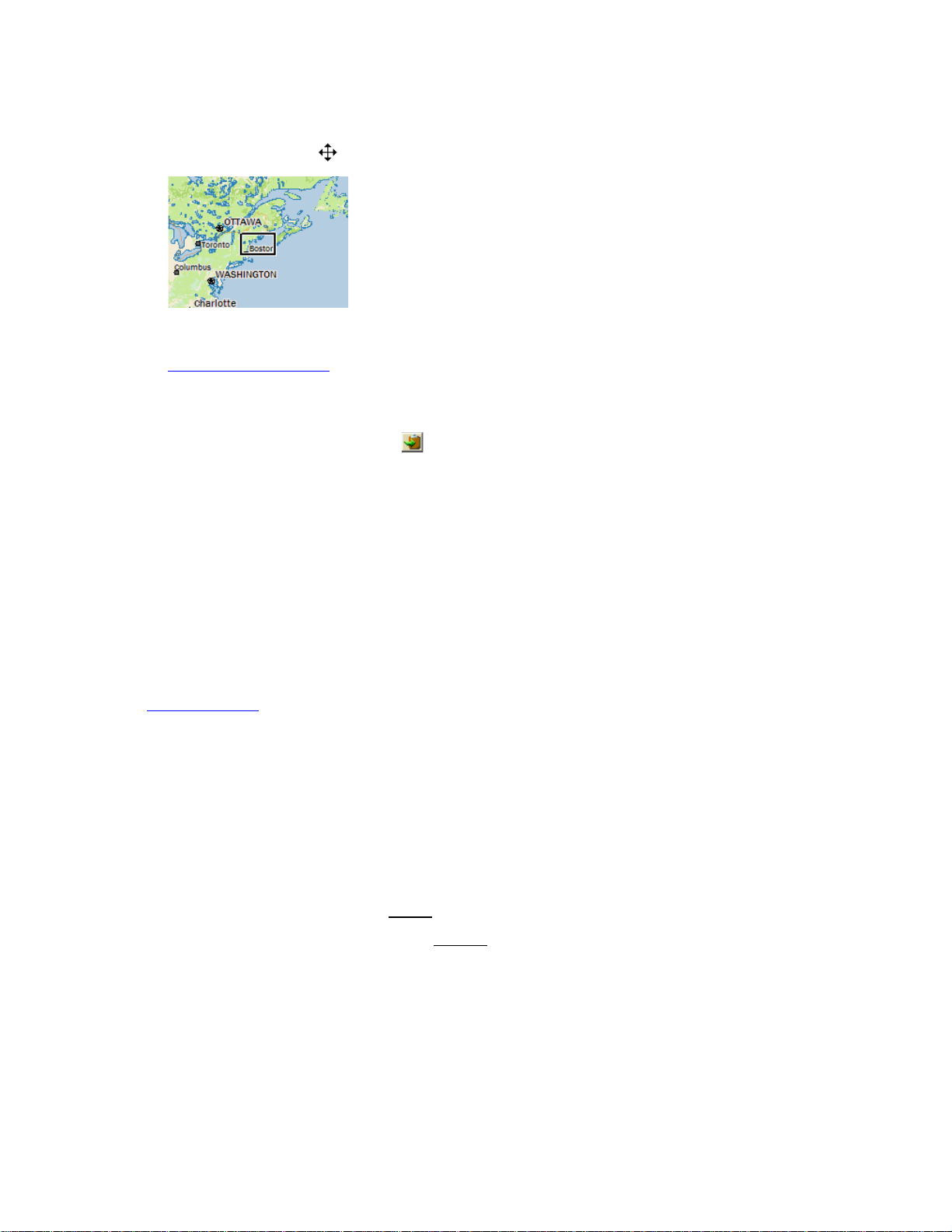
Topo USA User Guide
• Point anywhere on the black view box in the overview m a p wind ow. When the
pointer becomes a , drag the view box to the new location.
• Use the search features on the Find tab to center the map on a particular location.
• Assign shortcut keys
to pan the map up, down, left, or right in small increments.
Copying Your Map to the Clipboard
Click the Copy to Clipboard button on the Print tab to copy your map to the clipboard.
You can then paste it into another program.
You can also right-click anywhere on the map and click Copy Map to Clipboard.
Saving a Map as a Bitmap or JPEG Image
You can save the current map view as a bitmap (.bmp) or JPEG (.jpg) image in all page
layout formats: Single, 2 x 2, and 3 x 3. If you select a multi-page format, all the active
pages are saved as individual bitmaps or JPEGs. The file name is the specified file name
with an incremental page number at the end.
See Printing a Map
To Save a Map as a Bitmap or JPEG
Use the following steps to save a map as an image.
1. Locate the area on the map that you want to save as an image.
for information about printing a map without saving it as a file.
2. Click the Print tab and then click the Map subtab (if it is not already selected).
3. Under Map, select Left, Right, or Both.
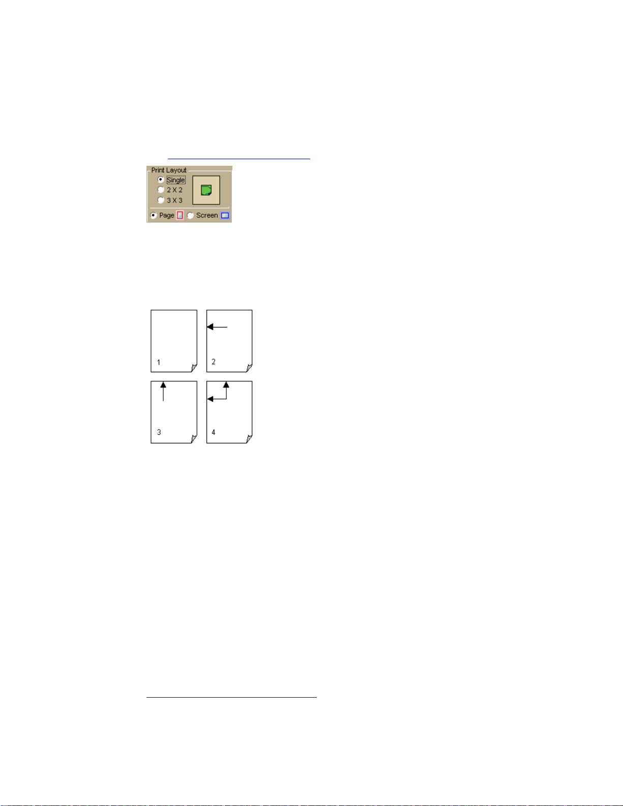
4. Under Print Layout, select Page(the map print area is based on the paper size
specified in the Setup options) or Screen(the map print area is based on the screen
size).
The print area for a Page map displays as a red box and the print area for a Screen
map displays as a blue box on the overview map.
5. If you selected Page in step 4, the follow ing options are available.
12
Getting Started
• Under Print Layout, select a layout option (Single, 2 x 2, or 3 x 3). The
print area displays on both the Map and the Overview Map. In the example
below, 2 x 2 is selected. This means the print area encompasses four
standard pages at whatever paper size you specified in the Setup options. You
can assemble a multi-page map
into a large map.
• If you selected 2 x 2 or 3 x 3 and do not want to save all the pages in the
multi-page map on the map layout graphic, click each page you do not want
to save. The page appears dimmed or gray. In the example below, page 4 will
not print.
• Verify this is the location and photo zoom you want to save. If not, pan the
map to the location and zoom to the level you want.
Note Changing the photo zoom enlarges/reduces the map features and
changes the map area that you save as an image. If you increase the photo
zoom level, map text, lines, symbols, etc. are larger and your map area is
reduced. If you decrease the photo zoom level, map text, lines, symb o ls, etc.
are smaller and your map area is enlarged. The reduction/enlargement
percentages for your photo zoom level display under the Photo Zoom dropdown list.
• If you want to use other tabs and functions but not lose your current print
area, print photo zoom, or other settings, select the Lock Print Center check
box. This locks the print area and changes the tab label to red.
• Add text or graphics to your map
.
13

Topo USA User Guide
• Select the Print Preview check box to zoom the map and view the entire
area that will be saved as a bitmap image. Clear the check box to return to
your previous data zoom level.
6. Click the Save button .
The Save 2D Map Image dialog box opens.
7. Type the file name in the File Name text box, select to save the file as a .bmp or
.jpg from the Save as Type drop-down list, select the DPI (dots per in ch) value
(optional), and click Save.
Measuring Distance and Area
Use the Measure tool on the toolbar to measure linear distance and area on the map
based on the units chosen in the Display tab of the Options dialog box.
The snap function snaps (attaches) the point of a measurement line to a point on a road or
another measurement object. This ensures a more accurate measurement of distance or
area. To measure area, you must completely enclose the area by snapping your finish point
to your starting point.
Notes
• The Measure tool is the best way to measure short distances on the map. If you want to
measure the distance of a road, try creating a route
area on the map, use the area object tools in the Draw tab.
• To disable the auto-snap function, hold down the ALT key on your keyboard while using
the Measure tool.
• Measure objects (lines and areas) are saved with the current map project. When you
create a new map project, the measure objects do not display. If you want the same
measure objects on your new project, you must recreate them.
• To view information about a measurement line, right-click it and click Info. The
measurement information is automatically displayed in the Info tab.
. If you want to measure a large
To Measure Distance or Area
Use the following steps to measure linear distance or area on the map.
1. Verify you have the correct units of measure selected in the Display tab of the
Options dialog box. For more information, see Setting Units of Measure Preferences
2. On the toolbar, click the Measure tool . The pointer changes to .
14
.
Getting Started
3. Click point-by-point to draw a measurement line on the map. A text box displays
next to your pointer indicatin g the total distance of the measurement taken.
Note When you pass over a point in a road, measurement line, or measurement
area to which you can snap, a yellow circle defines the snap point. Click to snap the
point of the measure line to the road or measurement object's point coordinate.
4. To end a measurement line, double-click the last point of the measurement line.
OR
Click the last point of your measure line or area and then click the Measure tool on
the toolbar.
The measure line is a two-pixel wide yellow line and the total length of the line is
displayed in a label at each endpoint of the line.
5. To end a measure area, hover over the starting point until the yellow snap circle
displays, and then double-click the last point to the starting point. The closure area is
transparently shaded, and the area and perimeter measurements display.
Chart of Supported Coordinate Formats
These are the supported search formats. Sample coordinates are for Yarmouth, Maine.
Tip Examples of search formats are listed in the Advanced search drop-down text boxes
along with a history of your most current search criteria.
Coordinate
Format
Latitude/Longitude N 43 48 30, W70 9 52 N 43 48 30 W70 9 52
QuickSearch Advanced Search
N 43 48.4910, W 070
09.8440
N434829.4600,
W0700950.6400
N43-48-30, W70-9-52 N43-48-30 W70-9-52
N 43 48.4910 W 070 09.8440
N434829.4600 W0700950.6400
N 43:48:29.46, W
70:9:50.64
4348, -7009 4348 -7009
N 43:48:29.46 W 70:9:50.64
15
Topo USA User Guide
4348N, 7009W 4348N 7009W
N4348, W7009 N4348 W7009
4348n, 7009w 4348n 7009w
n4348, w7009 n4348 w7009
4348 N, 7009 W 4348 N 7009 W
N 4348, W 7009 N 4348 W 7009
4348 n, 7009 w 4348 n 7009 w
n 4348 w 7009 n 4348 w 7009
434829, -700950 434829 -700950
4348.491, -7009.844 4348.491 -7009.844
4348.491, -7009.844 4348.491 -7009.844
434829.46, -700950.64 434829.46 -700950.64
43.80818333, -
70.16406667
43 48.4910 N, 70 09 50.64 W 43 48.4910 N 70 09 50.64 W
43 48.4910 n, 70 09 50.64
w
N 43 48.4910, W 70 09
50.64
434829.46 N, 700950.64 W 434829.46 N 700950.64 W
43, -70 43 -70
MGRS/USNG 19TDJ 06354 51187
43.80818333 -70.16406667
43 48.4910 n 70 09 50.64 w
N 43 48.4910 70 09 50.64 W
Same as QuickSearch
16
19TDJ0635451187
(NAD27)*
19TDJ06355109
19TDJ064511

19TDJ0651
UTM/UPS 19T 0406311E 4850964N Zone 19T
Easting 0406311E
Northing 4850964N
19T 0406311 4850964 Zone 19T
Easting 0406311
Northing 4850964
19T / 0406311 / 4850964 Zone 19T
Easting 0406311
Northing 4850964
Getting Started
SPCS
* Use this example for USNG with non-standard datum.
ME-W 0500490 0355150 Zone ME-W
Easting 0500490
Northing 0355150
Searching Tips
When you use the Quick Search subtab on the Find tab or the Route tab to search for a
location, you must enter the information in a specific format.
Tips
• Use punctuation as in the e xamples in the table below.
• Do not use periods.
• Search with the minimum amount of information to increase the number of results.
For example, if you search for Kalalau Trail in Hawaii but you are not sure of the
spelling, type "Kal, HI" and then scroll through the results until you find a match.
This table shows formats for search types.
For this type of search... Use this format... Example
Address
Street address, City, State
Street address, ZIP Code 100 Congress St, 04101
100 Baxter Blvd,
Portland, ME
17

Topo USA User Guide
Street address, City, State, ZIP
Code
City City, State Atlanta, Georgia
ZIP/Postal Code Within the U.S.: ##### (5-digit
ZIP Codes only)
Within Canada: ### (6-digit
Postal Codes only)
Minor Point of Interest POI name, City, State Subway, Columbus, OH
Major Point of Interest or
Landmark
Latitude/Longitude See Chart of Supported Coordinate Formats
For more information about the Find tab, see the Help topics under Finding a Location on
the Map.
POI/landmark name Mount Rushmore
POI/landmark name, State Space Needle, WA
100 Congress St,
Portland, ME 04101
04096
J8E756
Exiting the Program
To exit the program, click the Close button in the upper-right corner of the screen.
The Save Changes dialog box opens if you made changes to a project.
• Click Yes to save changes.
Note If only one change was made, the program closes after you save the project.
• Click No to discard changes and close the program.
• Click Cancel to return to DeLorme Topo North America.
No changes are saved.
If you made more than one change to the project or changes to more than one project,
once you save your project, the Exit dialog box opens.
• Click Save and Exit to save changes to the selected files and close the program.
Note Clear the check box for any file you do not want to save.
• Click No to discard changes and close the program.
• Click Cancel to return to DeLorme Topo North America.
No changes are saved.
18

Getting Started
About the Interface
Tab Area
You can access most of the application's functions from the tab area at the bottom of the
screen. To access Help for a specific tab, click the Help button on the tab. You can also
reorder the tabs, show or hide individual tabs or show or hide the tab panel
• Map Files
• Find
• Draw
• Route
• NetLink
• Handheld Export
• Info
• Profile
• 3-D
• Print
• Voice
• GPS
Control Panel
.
The Control Panel, located to the right of the map view, displays information pertinent to
the current map view and map cursor position. It also includes zoom and map pan buttons.
You can customize your interface to show or hide the Control Panel
.
19

Topo USA User Guide
Data Zoom Level—The current data zoom level of the map view; ranges
between 1-0 (maximum zoom out) and 17-0 (maximum zoom in).
Zoom Tools—Buttons that quickly zoom out three levels, out one level, or
in one level. For more information, see Zooming In and Out
.
Compass Rose—A group of nine buttons on a globe. The outer buttons
have yellow arrows; click one of the arrow buttons to pan the map in that
direction. Click the middle button to center the map on the previous map
view. This button performs an undo function for the last pan or zoom (up
to 256 times).
Map Rotation Tool—The arrow in the graphic indicates True North in
relation to the rotated map. Use the Map Rotation Tool to rotate the map
in any direction. You can rotate the map by click ing or dragging the square
map graphic in the direction you want or by selecting/typing the degree of
map rotation from the drop-down list.
Map Coordinates—Coordinates for the current map cursor position
display based on the units of measurement preferences
Display tab of the Options dialog box.
chosen in the
Elevation and Interval—Display in the measurement chosen in the
Display tab of the Options dialog box. The data zoom level affects interval
display.
Scale Bar—Indicates the distance one scale bar unit equals in the
measurement chosen under in the Display tab of the Options dialog box.
Overview Map
The overview map is a small map in the lower-right corner of the screen that offers a wideangle view of your current map view area. It is approximately three data zoom-levels out
from the current map view.
Tips
• Click anywhere on the overview map and that point becomes the new map center.
This allows you to travel greater distances with each mouse click than you can within
the larger, current map view.
20

Getting Started
• Use the black view box in the overview map window to pan the map. Point anywhere
on the view box. When the pointer becomes a , drag the view box to the new
location.
Toolbar
• You can show or hide toolbar options.
• You can change the order of the toolbar options.
Default Toolbar
This is the default toolb ar—click an area on the toolbar image for more information. You can
also view these topics in the Using the Toolbar section of the Help.
Additional Toolbar Options
These button groups are hidden in the default toolbar. To show a button group, right-click
the toolbar and click the check box next to the name of the group.
GPS/Nav Mode
Map Panning
Using the Help System
Help Overview
21

Topo USA User Guide
There are several ways to get more information about the program's features and
functionality.
Tips and Info
There are three ways help is provided within the program.
• Pop-up Tutorials
When you perform some actions in the program, a pop-up Did you know . . .?
tutorial opens. These provide additional information for using that particular function.
If you do not want to see that specific pop-up tutorial again, select the Do Not
Show Again check box before you close it.
If you do not want to see any pop-up tutorials, click the Help button on the toolbar
and then click Shut Off All Pop-Up Tutorials.
• ToolTips
When you point to a tool for a few seconds, a short label (ToolTip) describing the tool
displays on your screen. ToolTips also display in windows and dialog boxes when you
point to a button, icon, or other feature.
• Information Boxes
Several tabs contain information boxes. Information boxes provide descriptions
about the features and functions of the selected tab.
Help System
Click the Help button on the toolbar to view the Help menu, and then click an item to
select it.
Tip To access a Help menu item using its underlined letter, click the Help button and then
press the underlined letter for the item on your keyboard. For example, to access the Map
Legend, click the Help button and then press the M key on your keyboard.
Tab Help
To get specific help for the tab you are using, click the Tab Help button to open a
related Help topic. The button is available in the main tab area and in the Options dialog
box. In addition, many dialog boxes have a Help button that will open a help topic for a
particular task.
Glossary
22

Getting Started
See the Glossary Terms
topic.
Using the Help System
To open Help, click the Help button on the toolbar and then click Help Topics, or
press the F1 key on your keyboard. To open a task-related Help topic for the tab you are
working with, click the Help button on the tab.
• The Help system has four tabs.
Contents
To view an outline of the Help system contents, click the Contents tab.
• To view the additional topics under a particular book, double-click the
book.
• To view a topic, click the page.
Index
Use the following steps to search the Help system index.
o
1. While in the Help system, click the Index tab.
2. Type a keyword in the entry field. The list automatically scrolls to the
closest matching entry.
3. Double-click the topic.
OR
Click the topic and then click Display.
OR
Click the topic and press the ENTER key on your keyboard.
Note
o
• If you don't find what you're looking for in the index, click the Search
tab and try a search for your keyword.
o Search
Use the following steps to search for particular words or phrases within topics
in the Help system.
o
1. While in the Help system, click the Search tab.
23

Topo USA User Guide
2. Type a keyword in the entry field and then click List Topics or press
3. Double-click the topic under Select Topic to Display.
o Favorites
Use the Favorites tab to save topics for quick reference.
From the Help system, click the Favorites tab and then:
o
• To save a topic that you are viewing, click Add.
• To display a saved topic, double-click it in the list.
the ENTER key on your keyboard. A list of topics containing the
keyword displays.
OR
Click the topic and then click Display.
OR
Click the topic and press the ENTER key on your keyboard.
OR
Click it in the list of topics and then click Display.
• To remove a topic from Favorites, click it in the list and then click
Remove.
• You can move, resize, and minimize the Help window.
Printing Help Topics
To print any of the Help topics, select a topic (page with question mark) or heading (book
symbol) and then click Print. You can print the selected topic or a heading and all
subtopics.
OR
Right-click the topic displaying in the right window to print only that topic.
Tips
• Before you click Print, expand any links in the topic that include information you
want to print within your topic.
24

Getting Started
• To print all the Help topics, click the top level boo k in table of contents and then click
Print.
Web Help
A web version of the Help system is available on the DeLorme Technical Sup p o rt website.
On the support site, select your product from the Browse by Category drop-down list, and
click the link for Help top ics.
Help Documentation Conventions
The table below explains the formatting styles used in the Help documentation, including
links that expand, jump to another location within the same topic, or open a new topic.
The table below defines each convention and its use.
The convention... Is used for...
ALL CAPITALS Acronyms, names of certain commands, and keys on the
keyboard.
Note Use of the plus sign (+) between key names indicates key
combinations that perform various actions. For example, in the
directions "Press CTRL+SHIFT+F3 on your keyboard," you must
press and hold the CTRL and SHIFT keys while pressing F3.
Bold Command buttons, tab names, and options when used in
procedures and exercise steps. Also used for information that
25

Topo USA User Guide
you type exactly into a particular field.
Headings and table headings are bold for emphasis.
Italic Directory names and paths. Also used when referring to titles of
chapters, sections, and publications.
Blue underlined text Hyperlinks. These links act differently depending on their
context. When it is:
• Referenced with "for more information," the link goes to
another topic.
• Embedded in text, such as in the example "Open the file,"
the link goes to another topic, opens drop-down text that
expands within the same topic, or displays a secondary
window with a definition or graphic.
Red underlined text Opens expanding text that provides explanatory information. The
expanding text is italicized blue text.
Note
Notes
Tip
Tips
Additional information.
Helpful hints.
Glossary Terms
ADT
Alaska Daylight Time
Almanac
Data downloaded from satellites that contains the identity codes, location, and time
information for each satellite.
Arctic Circle
Parallel, or line of latitude around the Earth, at approximately 66°30' N. Because of the
Earth's inclination of about 23 1/2° to the vertical, it marks the southern limit of the area
26

Getting Started
within which, for one day or more each year, the Sun does not set (about June 21) or rise
(about December 21).
AST
Alaska Standard Time
Average Grade
Average of the grade from the start to the current cursor position (or finish).
Azimuth
The direction of travel or the direction between two points in reference to true or magnetic
north. When expressed in degrees, its value ranges from 0 to 360. A compass heading is an
azimuth. In most places, the word bearing has grown to mean the same thing as azimuth.
However, azimuth is always measured from true or magnetic north in a clockwise direction.
For example, due east is 90 and due west is 270. See also, Bearing.
Bearing
Like an azimuth, a bearing is measured in reference to true or magnetic north, but its value
never goes over 90. A bearing is always measured from the cardinal directions of north or
south. A typical bearing would be N45 E, which is the same as an azimuth of 45. The
bearing S45 W is an azimuth of 225. The use of the word bearing has changed over the
years and now means the same as azimuth. When tracking, bearing displays the direction of
travel between your current position and your next waypoint, relative to true or magnetic
North.
Bread crumb trail
A set of dots that display on your computer screen to record your progress as you travel.
CDT
Central Daylight Time
Climbing Distance
27

Topo USA User Guide
The total distance where the terrain is uphill.
Climbing Elevation
The amount of ascending vertical distance.
Coordinates
A set of numbers (e.g., latitude and longitude) used to identify the specific location of a
point.
Course
The azimuth and length of a line, considered together.
CST
Central Standard Time
Current Elevation
The elevation above sea level at a specific point.
Descending Distance
The total distance where the terrain is downhill.
Descending Elevation
The amount of descending vertical distance.
Differential GPS (DGPS)
A technique to improve GPS accuracy that uses pseudo-range errors recorded at a known
location to improve the measurements made by other GPS receivers within the same
general geographic area.
Dilution of Precision (DOP)
The total effect of all error sources in locating a position.
28

Getting Started
Download
To transfer information from a remote unit, such as a GPS receiver, to a computer.
EDT
Eastern Daylight Time
Easting
The measure of a position relative to the x-axis (horizontal) of a grid system.
Elevation Gain
The difference in elevation from the start of the profile to the end of the profile.
Ephemeris
Data that indicates the position and status of satellites.
EST
Eastern Standard Time
GMT
Greenwich Mean Time; used as the standard of time throughout the world.
GPS
Global Positioning System; a "constellation" of orbiting satellites used to calculate a precise
position on or near the earth's surface.
Grade
Actually percent grade, rise over run (100 x (rise/run)). For example, 6 means that for
every 100 ft, you gain 6 ft in elevation.
HDOP
29

Topo USA User Guide
Horizontal Dilution of Position; the measure of how much the geometry of the satellites
affects the horizontal position estimate.
Heading
Azimuth of the longitudinal axis of an aircraft or ship. Heading may differ from direction of
travel when flying or boating due to currents in the air or water.
Initialize
To set to a starting position, as in obtaining initial coordinates for a GPS receiver.
Latitude
The measure of a position on the earth's surface north or south of the equator in degrees,
minutes, and seconds. Defined as the angle from the equator's horizontal plane
perpendicular to the polar axis. All lines of latitude are parallel and are often referred to as
parallels.
Log
A record of the speed, direction, and route of travel as obtained via GPS.
Logging
Recording the speed, direction, and route traveled using GPS.
Longitude
The measure of a position on the surface of the earth east or west of the Prime Meridian in
degrees, minutes, and seconds. Defined as the angle from the vertical plane running
through the polar axis and the prime meridian. All lines of longitude meet at the poles and
are often referred to as meridians.
Maximum Elevation
The elevation of the highest point on a profile.
Maximum Speed field
30

When GPS tracking, displays your maximum speed.
MDT
Mountain daylight time
Minimum Elevation
The elevation of the lowest point on a profile.
MST
Mountain standard time
NMEA
Getting Started
National Marine Electronics Association
Northing
The measure of a position relative to the y-axis (vertical) of a grid system.
PDOP
The measure of how much the error in the position estimate produced from satellite range
measurements is amplified by a poor arrangement of satellites (with respect to the receiver
antenna).
Port
A hardware interface used by a computer to communicate with an external device.
PPS
Precise Positioning System; radio signals available to military and other authorized
personnel for GPS.
Real time
The actual time during which something takes place.
31

Topo USA User Guide
Receiver
Hardware device that receives data, such as from satellites.
Snapping
Attaching a point on one draw object to the exact coordinates of a point in another draw
object. You can snap the central shape point of an arc to another object or snap a routable
road to an existing road, enabling routing from the drawn road to the road system on the
map database.
Speed field
When GPS tracking, displays your speed as you travel.
Terrain Distance
The 3-D distance of the profile accounting for elevation rise and descent.
Third-party GPS device
A GPS receiver manufactured by a company other than DeLorme, such as GARMIN,
Magellan, Brunton, Lowrance, Trimble, and so forth.
Time field
When connected to a DeLorme GPS receiver, displays the Greenwich mean time.
Track
To observe or plot the moving path of an object.
Upload
To transfer information from a computer to a remote unit, such as a GPS receiver.
VDOP
32

Getting Started
The measure of how much the geometry of the satellites affects th e vertical pos ition
estimate.
Waypoints
Marked positions with specific coordinates that can be downloaded or uploaded.
Zone
A named grid system of any of the UTM/UPS, MGRS, or State Plane coordinate systems and
used as a basis for coordinate display. For example, UTM zone 19 specifies the six-degree
swath between longitude 66W to 72W and running from 84S to 80N. Another example is
zone ME-W in the State Plane coordinate system, which specifies an area that covers the
western half of Maine. When using one these coordinate systems, the current zone and
coordinates east and north (the eastings and northings) of the zone origin are displayed.
Recreational Contacts
Tip
You can find most trails using QuickSearch
can use the Advanced search option on the Find tab to search for trails:
• If you know the name of the trail you want to search for, select Name and/or
Category from the Find drop-down list and then select a Within option (U.S. State
is helpful when you do not know the city/town the trail is located in). Type the name
of the trail in the Name text box, type trail in the Keywords text box, type the
location information (if applicable), and then click Search.
• If you do not know the name of the trail, select Category from the Find drop-down
list and then select the Within optio n. Type trail in the Keywords text box, type
the location information (if applicable), and then click Search.
Click a link to jump to tha t place in the table.
• National Recreation Information
on the Find tab. If a search is not successful, you
• National Historic Trail Information
• National Scenic Trails
• Trails of Interest
33

Topo USA User Guide
tion:
tion:
National Recreation Information
Contact
Name
Web Site Information Phone
Number
Recreation.gov www.recreation.gov 877-444-
6777
National
Forest Service
www.fs.fed.us/ 800-832-
1355
NFS Locator www.fs.fed.us/recreation/map/state_list.shtml 202-205-
1706
National Park
Service
www.nps.gov NPS Center
for
Recreation &
Conserva
202-3546900
NPS Locator www.nps.gov/findapark/index.htm N/A
National
Monuments
www.blm.gov/wo/st/en/prog/blm_special_areas/NLCS/monuments.html BLM National
Landscape
Conservation
System:
202-2083516
National
Historic
Sites—NPS
www.nps.gov/nr/
NPS Center
for
Recreation &
Conserva
202-3546900
U.S. Fish and
Wildlife
www.fws.gov
800-344-
WILD
Service
34

Getting Started
Conservation:
National
Trails—BLM
National
Trails—NPS
National
Association of
RV Parks &
www.blm.gov/wo/st/en/prog/blm_special_areas/NLCS/Trails.html
BLM National
Landscape
Conservation
System:
202-2083516
www.nps.gov 202-208-
3100 or NPS
Center for
Recreation &
202-3546900
www.gocampingamerica.com
www.arvc.org
800-3952267
Campgrounds
(ARVC)
National Historic Trail Information
Trail Name State(s) Web Site Information Phone
Number
California
National
Historic Trail
CA, ID,
KS, MO,
NE, NV,
OR, UT,
WY
Info
Center:
MO
www.octa-trails.org/
www.nps.gov/cali/
816-2522276
El Camino
Real de Tierra
NM, TX,
Mexico
www.caminorealcarta.org/ 575-528-
8267
35

Topo USA User Guide
Adentro
Info
www.nps.gov/elca/
National
Historic Trail
Iditarod
National
Historic Trail
Juan Bautista
De Anza
National
Historic Trail
Lewis and
Clark National
Historic Trail*
Center:
NM
AK www.iditarodnationalhistorictrail.org/
www.blm.gov/ak/st/en/prog/nlcs/iditarod.html
AZ, CA,
Mexico
www.therapure.com/anza-trail/anzamen.htm
www.nps.gov/juba/
Info
Center:
CA
IA, IL,
ID, KS,
www.lewisandclark.org/
www.nps.gov/lecl/
MO, MT,
ND, NE,
OR, SD,
N/A
N/A
800-7013434
Mormon
Pioneer
National
Historic Trail*
Nez Perce
National
Historic Trail
Old Spanish
National
Historic Trail
WA
Info
Center:
MT
IA,
IL,NE,
UT, WY
ID, OR,
MT, WY
Info
Center:
ID
AZ, CA,
CO, NM,
NV, UT
www.mormontrails.org/
www.nps.gov/mopi/
www.nezpercetrail.net/
www.fs.fed.us/npnht/
www.oldspanishtrail.org/
www.nps.gov/olsp/
N/A
208-9400053
505-4256039
36

Getting Started
Oregon
National
Historic Trail
Overmountain
Victory
National
Historic Trail
Pony Express
National
Historic Trail*
CA, ID,
KS, MO,
NE, NV,
OR, UT,
WY
Info
Center:
MO
NC, SC,
TN, VA
Info
Center:
SC
CA, CO,
KS, MO,
NE, NV,
www.octa-trails.org/
www.nps.gov/oreg/
www.ovta.org/
www.nps.gov/ovvi/
www.xphomestation.com/
www.nps.gov/poex/
888-8116282
N/A
N/A
Santa Fe
National
Historic Trail
Selma To
Montgomery
National
Historic Trail
Trail of Tears
National
Historic Trail*
UT, WY
CO, KS,
MO, NM,
www.santafetrail.org/
www.nps.gov/safe/
OK
Info
Center:
NM
AL www.nps.gov/semo/
AL, AR,
GA, IL,
www.nationaltota.org/
www.nps.gov/trte/
KY, MO,
MS, NC,
620-2852054
334-877-
1984/334872-0509
501-6669032
OK, TN
37

Topo USA User Guide
Info
Center:
AR
* A trail that is a point in the data, but cannot be searched for using the Find
functionality.
National Scenic Trails
Trail Name State(s) Web Site Information Phone Number
Appalachian
National Scenic
Trail
Appalachian
Trail
Conservancy
Continental
Divide National
Scenic Trail
Florida National
Scenic Trail
CT, GA, MA, MD,
www.nps.gov/appa/index.htm
304-535-6278
ME, NC, NH, NJ,
NY, PA, TN, VA,
VT, WV
Info Center: WV
WV www.appalachiantrail.org
www.nps.gov/appa/
Appalachian
Trail
Conservancy:
304-535-6331
CO, ID,MT,
www.fs.fed.us/cdt
888-909-CDTA
NM,WY
Info Center: CO
FL www.floridatrail.org/ 877-HIKE-FLA
Ice Age National
Scenic Trail
Natchez Trace
National Scenic
Trail
North Country
National Scenic
Trail
38
WI www.iceagetrail.org/
www.nps.gov/iatr/
AL, MS, TN
www.nps.gov/natt/
N/A
Info Center: MS
MI, MN, ND, NY,
OH, PA, WI
www.northcountrytrail.org/
www.nps.gov/noco/
Info Center: MI
800-227-0046
866-445-3628

Getting Started
Phone
Numbe
Pacific Crest
National Scenic
CA, OR, WA
Info Center: CA
www.pcta.org/
www.fs.fed.us/pct/
919-285-1846
Trail
Potomac
Heritage
National Scenic
DC, MD, PA, VA,
WV
Info Center: WV
www.potomactrail.org/
www.nps.gov/pohe/
571-436-7801
Trail
Trails of Interest
Trail Name State(s) Web Site Information
Abol Trail ME www.mainerec.com/baxter1.asp?Category=101&PageNum=101 N/A
Achenbach
Trail
ND www.nps.gov/thro/planyourvisit/hiking-and-trail-information.htm N/A
Balsam
Mountain
Trail
Black Creek
Trail
Black
Heritage
Trail
Chattanooga
Trail
Chilkoot
Trail
NC, TN www.nps.gov/grsm/
865-
4361200
MS www.fs.fed.us/r8/mississippi/ 601-
9651600
MA www.nps.gov/boaf/planyourvisit/things2do.htm
www.afroammuseum.org/trail.htm
6177425415
SC www.sctrails.net/trails/ALLTRAILS/Hiking/Upcountry/Chattooga.html 803-
7340173
AK,
Canada
www.nps.gov/klgo/planyourvisit/chilkoottrail.htm 907-
9832921
Freedom MA www.thefreedomtrail.org/ 617-
39

Topo USA User Guide
Trail
357-
8300
Glacier
Gorge Trail
CO www.nps.gov/romo/planyourvisit/list_hiking_trails.htm 970-
5861206
John Muir
Trail
CA www.pcta.org/about_trail/muir/over.asp 916-
2851846
Kalalau Trail HI www.hawaiistateparks.org/hiking/kauai/Index.cfm?hike_id=13 808-
5870300
Kekekabic
Trail
MN www.kek.org/index2.html 800-
818HIKE
King Ravine
Trail
NH www.fs.fed.us/r9/forests/white_mountain/recreation/hiking/ 603-
5366100
Long Path NJ, NY www.nynjtc.org/panel/gohiking 201-
5129348
Long Trail VT www.greenmountainclub.org/page.php?id=2 802-
2447037
Ouachita
AR, OK www.friendsot.org/
N/A
National
Recreation
Trail
Outer
TX www.nps.gov/bibe/planyourvisit/oml-itinerary.htm
N/A
Mountain
Loop Trail
40

Getting Started
Ozark
Highlands
National
MO
www.arkansas.com/outdoors/hiking/traildetail.aspx?type=B&trail=Ozark Highlands Trail
479968-
2354
Recreation
Trail
Pinhoti Trail AL www.alabamatrail.org/hikingAL/Pinhoti/PinhotiI.htm N/A
Ruby Crest
National
Recreation
NV www.fs.fed.us/r4/htnf/
775-
331-
6444
Trail
Sheltowee
Trace
National
KY www.sheltoweetrace.com/
www.fs.fed.us/r8/boone/recreation/sheltowee.shtml
859-
745-
3100
Recreation
Trail
Shining Sea
MA www.capecodbikeguide.com/shiningsea.asp N/A
Bike Trail
Slickrock
Bike Trail
UT www.utah.com/bike/trails/slickrock.htm 800-
635-
6622
Snack Den
Ridge
NC, TN www.nps.gov/grsm/ 865-
436-
1200
Teton Crest
WY www.nps.gov/grte/ N/A
Trail
Timberline
Trail
OR www.fs.fed.us/r6/mthood/ 503-
668-
1700
Tonto Trail AZ www.nps.gov/grca/planyourvisit/campsite-information.htm 928-
41
638-

Topo USA User Guide
7888
Wild Azalea
Trail
Wonderland
Trail
LA www.fs.fed.us/r8/kisatchie/ 318-
473-
7160
WA www.nps.gov/mora/planyourvisit/the-wonderland-trail.htm 360-
569-
2211
42

Map Legend
The features that display on the map may display differently depending on which map colors
you chose on the Display tab of the Options dialog box. The tables below show the
symbolization of each feature, by map color.
Notes
• Not all features are available at all zoom levels.
• Not all features are available in all datasets.
• High-contrast Color features display the same as Street Color features (except for land,
which displays as black).
Routable Trail Features
Topo
Colors
Street
Colors
Description
Major Trail (National Scenic, National Historic, etc.)
4-wheel Drive Trail
Trail/Walkway/Foot Trail
Important Some trails may cross private property. Contact the applicable trail department
to ensure you have the appropriate permissions before following a major trail. For contact
information, see Recreational Contacts
.
Routable Road Features
Ferry Passenger
Ferry Vehicle
Interstate Highway (can also include this symbol: )
Limited Access Road
Local Road
Major Connector, Forest Road
Minor Connector
Non Limited Access Interstate
43

Topo USA User Guide
Primary State Route
State Route (can also include this symbol: )
Toll Road
U.S./National Route (can also in clude this symbol: )
Unclassified Road
Unimproved Road
Land Cover
Topo
Colors
Street
Description
Colors
n/a Bare Rock or Sand
Bureau of Land Management La nd
Bureau of Mine Reclamation Land
n/a Forest, evergreen
n/a Forest, mixed
Ice or Snowfield
Indian Reservation (at data zoom level 11)
Indian Reservation (at data zoom level 2 thru 10-7)
Intermittent Water
Land
44
n/a Mine or Quarry
n/a Transitional Area, Lava, Salt Flats, or Mixed Barren
Military Area (at data zoom level 11)
Military Area (at data zoom level 2 thru 10-7)
Parks
River/Stream

Map Legend
n/a Wetlands
Point Features
Topo
Colors
Street
Colors
Water
Description
Amusements
Airport (private)
Airport (commercial public)
Airport (general aviation public)
Business (Amusement, Recreation, Specialty or Dept.
Store)
Camping (at data zoom level 14)
Camping (at data zoom level 11 thru 13)
Cemetery
Educational Facility
Exit, with services (at data zoom levels 10 thru 11-7)
Exit, without services (at data zoom levels 10 thru 11-7)
Exit, food (at data zoom levels 12 thru 17)
Exit, gas (at data zoom levels 12 thru 17)
Exit, lodging (at data zoom le vels 12 thru 17)
Exit, other (at data zoom levels 12 thru 17)
Family Outings
Fast Food
Gas
Hospital
45

Topo USA User Guide
Lodging
Metropolitan City
Military Base
National Capital (data zoom level 7 thru 10)
National Capital (data zoom levels 2 thru 6)
Outdoor Adventures
Point of Interest
Population Center
Public Service
Religious (buildin gs)
Rest Area with Facilities (at data zoom levels 10 thru 11)
Rest Area with Facilities (at data zoom level 12)
Line Features
Topo
Colors
Street
Colors
Rest Area without Facilities (at data zoom levels 10 thru
11)
Rest Area without Facilities (at data zoom level 12)
Restaurants (general)
Restaurants (specialty)
Small City
State Capital
Unique Natural Feature (at data zoom level 8)
Description
County Boundary
46
Dam

Map Legend
Game Management District
International Boundary
Park Boundary
Pipeline
Power Line
Railroad (Abandoned)
Railroad
Runway
State Boundary
DeLorme Atlas and Gazetteer Symbols
Symbol Description
Developed Boat Ramp (at data zoom levels 11 and 12)
Developed Boat Ramp (at data zoom level 13)
Freshwater Fishing (at data zoom levels 11 and 12)
Freshwater Fishing (at data zoom level 13)
Hunting (at data zoom levels 11 and 12)
Hunting (at data zoom level 13)
Saltwater Fishing (at data zoom levels 11 and 12)
Saltwater Fishing (at data zoom level 13)
Undeveloped Boat Ramp (at data zoom levels 11 and 12)
Undeveloped Boat Ramp (at data zoom level 13)
47


Using the Toolbar
Showing/Hiding Toolbar Options
You can customize the toolbar to show the options you use most. You can also activate
toolbar options that are not turned on by default or hide or show the entire toolbar. Some
toolbar options are grouped—for these, you can show or hide the group of buttons.
To Modify the Toolbar
1. Right-click the toolba r .
Toolbar options with a selected check box next to them are displayed on the toolbar.
2. Click an item to activate or inactivate it in the toolbar.
Reordering the Toolbar Options
To reposition the toolbar groups horizontally or vertically, just drag the dotted vertical bar
that separates each group to the new location (left, right, up, or down).
To Create a New Project
To create a new project, click the New button on the toolbar. If you made changes to
the open project, the Save Changes dialog box opens to ask you if you want to save your
changes.
For more information, see Creating and Deleting Projects
.
To Open a Project
To open an existing project:
49

Topo USA User Guide
1. Click the Open button on the toolbar.
OR
Click the arrow next to the Open button, and then click Open Project.
If you made changes to a project that is already open, the Save Changes dialog box
opens. Note Map Files have .tpx and are saved by default in C:\DeLorme
Docs\Projects.
The Open File dialog box opens.
2. Select the project you want to view and click Open.
For more options for opening files, see Opening an Existing Project
.
To Save a Project
To save the project that is currently open:
1. Click the Save button on the toolbar.
The Save File dialog box opens.
2. Browse to the location where you want to save the project.
If you want to rename the project, type a new name in the File Name text box.
3. Click Save.
To Open the Map Library
To open the Map Library subtab on the NetLink tab, click the Map Library button.
To Share Maps
To share your current map view, a route map and directions, or a profile, click the
MapShare button on the toolbar to open the MapShare Wizard.
MapShare lets you share maps—even 3-D maps, routes, and profiles.
For information on emailing maps, routes, and profiles with the MapShare Wizard, click the
Help button in the MapShare Wizard.
To Create a Route
To set route points using the toolbar:
1. Type the location where you want to start your route in the Start text box (next to
the green Start button).
OR
Click the green Start button and then click the location on the map where you
50

Using the Toolbar
want to start your route.
OR
Select an address book entry, a previous location, or your current GPS position from
the Start drop-down list.
2. Type the location where you want to end your route in the Finish text box (next to
the red Finish button).
OR
Click the red Finish button and then click the location on the map where you
want to end your route.
OR
Select an address book entry or your current GPS position from the Finish dropdown list.
3. Optional. If you want to add a stop or via to your route, click the Stop button or
the Via button and then click the location on the map where you want to add or
insert the stop or via. Repeat this step for each stop or via you want to add to your
route.
Note If the Add option is selected in the Route tab, stops and vias are added in the
order they are added to the route. If the Insert option is selected in the Route tab,
stops and vias are added in the order they are approached in the route. For more
information, see Adding and Inserting Stops and Vias
.
4. Click the Calculate button .
Notes
• If you have only the left map window open, the route Start, Finish, and Stop
buttons on the toolbar and on the Route tab are grayed out. To activate the options,
use the map resize tool
to expose the right map window.
• To use the current GPS location in a route, you must connect your device to your
computer and click the GPS button on the toolbar (hidden
by default) or on the
GPS tab.
• Once a route is calculated, you can use the subtabs in the Route tab to view route
directions, edit a route, and more. Click the Directions subtab to view the route
directions, the Advanced subtab to display the advanced routing options, or click
Back on Track to add your current GPS position as a stop to the current route.
51

Topo USA User Guide
To Sync Files and Information with a Handheld GPS Device
Click the Sync button on the toolbar (also on the GPS and Handheld Export tabs) to
open the Earthmate® GPS Sync dialog to sync maps, waypoints, geocaches, tracks, and
routes with an Earthmate PN-Series GPS device.
If you are using another device, click the arrow to open the sync menu and select Other
Device to open the Exchange Wizard.
For more information on syncing information, see the Help topics listed under Using
Earthmate PN-Series GPS Devices or Using Thir d-Party GPS Devices.
To Measure Distance
Use the following steps to measure linear distances and perimeter/area on the map. For
more information, see Measuring Distance and Area
1. Click the Measure tool on the toolbar.
2. Click point-by-point to draw a measurement line on the map. A text box displays
next to your pointer indicatin g the total distance of the measurement taken.
Note When you pass over a point in a road, measurement line, or measurement
area to which you can snap, a yellow circle defines the snap point. Click to snap
the point of the measure line to the road or measurement object's point coordinate.
Press and hold the ALT key on your keyboard to disable snapping.
3. To end a measurement line, double-click the last point of the measurement line. The
measure line displays as a two-pixel wide yellow line and the total length of the line
displays in a label at each endpoint of the line.
4. To end a measure area, hover over the starting point until the yellow snap circle
displays and then double-click the last point to the starting point. The perimeter
measurements display.
.
To Get Information About a Location
Use the Information button on the toolbar to click a point, symbol, feature,
measurement line, track, or area on the map to identify it and view detailed information
about it.
The Information button is hidden by default
menu and click Information.
52
; to show it, right-click the toolbar to open the

Using the Toolbar
Use the following steps to get information about a particular map feature.
1. Click the Information button.
2. Click the map feature you want information for, such as a road, town, measurement
line, waypoint, track, draw symbol, or point of interest.
The Info tab opens and displays a list of information categories.
Note Descriptive information may include a name or feature type, length/area,
ZIP/Postal Code, town name, county name, state/province, coordinates, and
Standard Industrial Classification categories.
3. Click the plus sign next to each of the information categories to expand the category
to view more detailed information.
OR
Right-click in the information box and click Expand All to expand all of the
information categories. Right-click in the information box again and click Collapse
All to minimize all of the information categories.
4. Optional. Repeat steps 1–3 to get information about another location.
5. Optional. Right-click in the information box and click Print to print your map feature
information.
Notes
• You can also get information about a location using the right-click option. Jus t r ightclick the location and click Info.
• The status bar (located above the tab area) displays draw object type, draw file
information, point of interest name (if applicable), street name/address, highway, city,
state/province, and ZIP/Postal Code information for the map location that your cursor is
positioned on.
• Some map features (such as campgrounds, national scenic/historic trail information
centers, and state parks) display with a blue outline at higher data zoom levels. The
blue outline indicates that the feature has a hyperlink to its website. To open the
hyperlink, right-click the feature and then click Open Hyperlink OR click the URL in the
Info tab.
To Create a Profile
To create a profile:
53

Topo USA User Guide
1. Center your 2-D map
OR
Center the route
2. Click the Profile button on the toolbar.
3. Move your pointer over the map. The pointer changes from to when it
passes over an object that you can profile.
4. Select a linear object or route on the map to generate its profile.
When the object is selected, it is highlighted and the Profile graph displays in the
Profile tab area.
Note Move your pointer along the elevation profile in the Profile graph. The
intersection of the vertical and horizontal blue lines travels along the top of the
terrain profile. These lines indicate the height and distance of the particular location.
A small crosshair follows along the corresponding object on the map.
You can also right-click a linear object or route on the map and click Profile. For more
on the area with the linear object you want to profile.
you want to profile on the map.
information about profiles, see the Help topics under Profiling Linear Objects.
To Add Images and Data to a GPS Location
To open the GeoTagger Wizard, where you can combine images and data with GPS
information on the map, click the GeoTagger button on the toolbar.
The Geotagger button is hidden by default
menu and click Geotagger.
For more information, see Getting Started with GeoTagger.
; to show it, right-click the toolbar to open the
To Choose Options
To open the Options dialog box, click the Options button on the toolbar. Use the
Options dialog box to set preferences for program options.
The Options dialog box has the following tabs:
• GIS
• GPS
• Sync
• Voice
• Find (GPS Radar)
54

Using the Toolbar
• Map Features (Basic and Custom
• Display
• Keyboard Shortcuts
• 3-D
An Options button that opens the Options dialog box is also available on the 3-D, Find >
GPS Radar, and GPS tabs.
To open the Options menu, click the arrow next to the Options button on the
toolbar. The following menu options are available:
• Options—Opens the Options dialog box.
• Tab Manager—Opens the Tab Manager dialog box where you can
individual tabs and reorder tabs.
• Netbook Mode—Allows you to turn the Netbook Mode on or off. If the mode is
turned on, the check box next to it is selected. Click Netbook Mode to turn i t on or
off. For more information, see Using Small-screen Devices
)
show or hide
.
You can also customize your interface:
• Show Tab Area Panel—Allows you to show or hide all the tabs. If Show All Tabs is
turned on, the check box next to it is selected. Click Show Tab Area Panel to show
or hide the tab area.
• Show Control Panel—Allows you to show or hide the Control Panel. If Show Control
Panel is turned on, the check box next to it is selected. Click Show Control Panel to
show or hide it.
To Grab and Pan the Map
To drag and pan the 2-D or 3-D map in any direction, click the Map Panning button on
the toolbar.
The Map Panning button is hidden by default
menu and click Map Panning.
Tip With your cursor anywhere on the map, press the CTRL key on your keyboard—the
cursor becomes a white hand. Hold down your left mouse button to drag the map to a new
location.
; to show it, right-click the toolbar to open the
To Start/Stop Your GPS Connection
55

Topo USA User Guide
The GPS button on the toolbar lets you start your GPS connection if the device is not active
or stop the connection if it is active.
The GPS button is hidden by default
GPS/NavMode.
To start or stop your GPS connection, click the GPS button on the toolbar.
• If you are using NavMode
but you can show them. For more information, see Customizing the Interface.
• If you start a connection and you are not using NavMode, the GPS tab area opens so
you can monitor your GPS status
Note NavMode is enabled by default. If you want to use the GPS tab for your default mode,
you can disable NavMode
on the GPS tab in the Options dialog.
; to show it, right-click the toolbar and click
, the GPS tab is minimized and the Control Panel is hidden,
.
To Use GPS NavMode
NavMode offers a hands free, full-screen view that you can view in 2-D or 3-D.
The NavMode button is hidde n b y d e fa ult
GPS/NavMode.
To Turn NavMode On/Off
; to show it, right-click the toolbar and click
Click the NavMode button to turn it on or off. The button is grayed out unless you
have a GPS device plugged in or are playing back a GPS log file
indented , NavMode is on.
You can also change your GPS view in the Options dialog box:
1. Click the Options button on the toolbar and click the GPS tab.
OR
Click the Options button on the GPS tab.
2. Clear the Use NavMode check box if you do not want to use NavMode when you
start your GPS. Select the check box if you do want to start GPS in NavMode.
3. Click OK.
. When the button appears
To Print
56

Using the Toolbar
To print a map using the current settings in the Print tab, click the Print button on the
toolbar.
The Print button is hidden by default
and click Print.
For more information, see Printing a Map.
; to show it, right-click the toolbar to open the menu
To Print the Map Screen
To print the current view as it displays on the screen, click the Print Screen button on
the toolbar.
The Print Screen button is hidden by default
menu and click Print Screen.
; to show it, right-click the toolbar to open the
57


Customizing the Map and Tab Display
Display Options Overview
The following topics e xplain how to use the Display o ptions in the Options dialog box:
• Displaying Basic Map Features
• Customizing the Interface
• Customizing the Map Features Preferences
• Changing the Map Colors
• Changing the Map Magnification Level
• Changing the Contour Detail Preferences
• Changing How POIs Display on the Map
• Setting Units of Measure Preferences
Customizing the Interface
You can customize the interface for your application by hiding the tab panel area and the
Control Panel. If you optimized your installation for use with a netbook, you can turn
Netbook Mode on or off.
To Customize the Interface
1. Click the arrow next to the Options button on the toolbar.
2. To turn on an option when it is not selected, click it to select the chec k box.
OR
To turn off an option when it is selected, click it to clear the check box.
• Use Tab Manager to show or hide individual tab s or reorder tabs
• Use Show Tab Area Panel to show or hide the entire tab area.
• Use Show Control Panel to show or hide the Control Panel.
• Use Netbook Mode to turn the optimized small-screen device view on or off.
For more information, see Using Small-screen Devices
Notes
• You can also use keyboard shortcuts
• Your settings are saved until you change them.
• Click Options in the menu to open the Options dialog box.
to customize the interface.
.
.
59

Topo USA User Guide
Displaying Basic Map Features
You can show or hide basic map features on your map.
You can also customize map features and customize the interface
Notes
• If you cannot make changes to the basic preference check boxes, verify the Use
Custom Map Features check box is not selected.
• Click Use Defaults to change the map feature settings to the default preferences.
• The map features available are based on the Map Colors option
.
you are using.
To Select Basic Map Feature Preferences
Use the following steps to change the basic map feature preferences. Changes made to the
map view display almost immediately after selection.
1. Click the Options button on the toolbar.
OR
Click the arrow next to the Options toolbar button to open the menu. Then, click
Options to open the dialog box.
2. Click the Map Features tab.
3. Select the check box next to th e map features you want to display on the map.
OR
Clear the check box next to the map features you want to hide on the map.
• Shaded Relief
Shaded relief becomes visible at data zoom level 6-0 or greater. It simulates
the effect of sun shining on terrain features and casting shadows, providing
greater depth perception of the image. Lighter shades of gray indicate gentle
terrain and darker shades indicate steep terrain. Using shaded relief may slow
down the draw time of the map screen as you pan.
• Contours
Contour lines are available at data zoom level 6-0 or greater. Contour lines
show the elevation of the land in feet or meters. The closer the contour lines,
the greater the slope. The distance between the lines is the contour interval,
which is indicated in t he Control Panel (distance units
Options dialog box).
• Land Cover
are controlled in the
60

Customizing the Map and Tab Display
Land cover colors are available at all data zoom levels. Colors indicate
vegetation and land cover areas on the map such as rock and sand, forests,
transitional areas, and wetlands.
• Grids
The Grids option can be used to identify coordinate points on the map. Grid
lines automatically adjust for the data zoom level of your map.
• Parks or Reserves
Parks and Reserves are available at data zoom level 7-0 or greater and
include areas such as parks, preserves, recreational area and public forests.
• Publicly Managed Lands
Publicly Managed Lands are only available when the Bureau of Land
Management (BLM) dataset is downloaded and installed. The feature includes
areas such as lands managed through the Bureau of Land Management and
displays at all data zoom levels.
• Game Management Districts
Wildlife Management U n its are only available when the Wildlife Management
Units (WMU) dataset is downloaded and installed. The feature includes areas
of managed wildlife and game and displays at data zoom level 6-0 or greater.
• USGS Quadrangle Coverage
The USGS 7.5 minute quadrangle coverage is indicated by red lines. These
display at data zoom level 8-0 or greater. Quadrangle names display at data
zoom level 9-0 and higher. To view quad info such as Orig Date and Quad
Order ID number (needed when purchasing quads), right-click a point within
the quad and then click Info. An information box displays in the lower-right
corner of the screen.
• 3DTQ Region Coverage
Displays the DeLorme 3DTQ product CD volume label, which covers each map
area at data zoom level 10-0 or greater.
• Map Center Crosshair
The map center crosshair indicates the map center at any data zoom level.
• Exits
View exits on primary limited access roads, interstates, and toll roads.
Available at data zoom level 10-0 or greater.
61

Topo USA User Guide
• One Ways
One ways display as bright green triangles on roads, pointing toward the
direction of travel (most noticeable in large cities). They are available at data
zoom level 13-0 or greater.
• Places (Minor)
View smaller towns, suburbs, locales, and natural features. Zoom levels vary.
• Roads (Minor)
View secondary roads, local and rural routes, trails, and railroads. Zoom
levels vary.
• Points of Interest
• Major—View many different points of interest, including recreational
• Minor—View general points of interest including educational,
areas, public safety, rest areas, and more.
technology, government, and religious buildings/locations.
• Business (Major)—View many different travel-related points of
interest including hospitals, camping, restaurants, and more.
• Business (Minor)—View general points of interest including small
shops and food stores, laundromats, and golfing.
• ZIP-Postal Codes
ZIP/Postal Code boundaries display at data zoom level 8-0 and greater, with
ZIP/Postal Code labels displaying at data zoom level 10-0 and greater.
• Town Borders
• View town borders at data zoom level 10-0 and greater for the
following states:
Arkansas
Connecticut
Illinois
Indiana
Iowa
Kansas
Louisiana
Maine
Maryland
Massachusetts
Michigan
Minnesota
Mississippi
Missouri
Nebraska
New
Hampshire
New
Jersey
North
Carolina
North
Dakota
Ohio
Pennsylvania
Rhode
Vermont
Virginia
Washington
DC
West
Virginia
Wisconsin
62
Island

Customizing the Map and Tab Display
New York
South
Dakota
•
• County Borders
View shaded outlines of U.S. counties at data zoom levels 7-0 or greater.
• International Labels
View country labels at data zoom levels 1-0 through 4-0.
• Urban Area Color
Displays a shaded map area in populated regions at data zoom levels 5-0.
4. Click OK to commit the change and exit the Options dialog box.
OR
Click Apply to commit the change and keep working in the Options dialog box.
Customizing the Map Feature Preferences
You can change the display of a wide variety of map features so you can customize your
map to meet your specific needs. You can even customize which POIs display.
To Set Custom Map Features
This is an advanced feature that lets you create a specific, custom set of map features for
your map display from hundreds of options. Note that changes are not visible until you click
the Done button.
1. Click the Options button on the toolbar.
OR
Click the arrow next to the Options toolbar button to open the menu. Then, click
Options to open the dialog box.
2. Click the Map Features tab.
3. Select the Use Custom Map Features check box and then click Customize
Features to display the custom options.
Note Custom map feature selections override selections in the basic features list.
4. To quickly search for a particular type of feature, type the name of the item in the
Search text box.
A list of matching keywords displays and corresponding feature types are listed in
63

Topo USA User Guide
the Search Results window. Results for the number of keywords and types found
also display.
A selected check box indicates the feature displays on the map.
• Select/clear the individual feature check box to show or hide that feature.
• Click the small None button to the right of the Search Results window to
show none of the features listed.
• Click the small All button to the right of the Search Results window to
display all of the features listed.
• Click Only to display only those features listed in the Search Results
window.
• Click Exclude to display all features except those listed in the Search
Results window.
5. To use the map feature tree to select which POIs display on the map, click the plus
signs to expand the individual branches. A selected check box indicates the feature
type displays on the map.
Note Some branches expand further than others. Selecting/clearing a check box at
a certain branch of the tree shows/hides all the items below that level.
• Select/clear the individual map feature check box to show or hide that
feature.
• Click All to select all map features in the program.
• Click None to select none of the types in the program.
Note A small number of features cannot be turned off. They are part of the
base map display and cannot be changed. This is why certain levels on the
tree remain unavailable (appear dimmed or gray).
6. Click OK to accept the change and exit the Options dialog box.
OR
Click Apply to accept the change and keep working in the Options dialog box.
Notes
• When you save the current project, the following feature preferen ces are saved in
reference to map features:
o Major map features preferences
o Individual custom feature preferences
64

Customizing the Map and Tab Display
o When you create a new project, the current map settings are used. Click Use Defaults
to return to the default settings.
Changing the Map Colors
When you use a laptop computer while traveling, it can be difficult to see the map display
on your screen. This can be especially true at night or on a bright sunny day. Changing your
default map colors to high-contrast map colors can make your map display easier to see.
To Change the Map Colors
Use the following steps to change the map display.
1. Click the Options button on the toolbar.
OR
Click the arrow next to the Options toolbar button to open the menu. Then, click
Options to open the dialog box.
2. Click the Display tab.
3. From the Map Colors drop-down list, select High-Contrast Colors to make the
map display darker for improved in-vehicle visibility, Street Colors to emphasize
streets and highways on the map, or Topo Colors to emphasize contours, parks and
public lands, land cover, and so on.
4. Click OK to accept the change and exit the Options dialog box.
OR
Click Apply to accept the change and keep working in the Options dialog box.
Showing Hybrid Maps
Raster data, such as aerial and satellite data, is image-based and does not provide typical
map information, such as street names, route numbers, and so on. The Hybrid Map feature
in the left map window lets you overlay this type of map information onto raster data.
Note You cannot create a route in the left map window. Once you create a route in the
right map window, the route line displays in the left map window.
To Show Roads and Text Labels on Imagery
Use the following steps to show roads, road names and numbers, names of bodies of water
and more on imagery in the left map window.
1. Ensure the left map window is displaying and your raster data, such as Satellite
Imagery (Sat 10) or Aerial Imagery (DOQQ),is displayed.
65

Topo USA User Guide
2. At the top of the left map window, select the raster dataset from the data drop-down
list.
3. Click the Hybrid Map button. All roads, contours, points, text labels, and so on
display identically to the data that is display e d in the right map window.
Note The Hybrid Map button is unavailable for vector dataset types.
Changing the Map Magnification Level
If you want to change the size of the map image, but not change the degree of geographic
detail on the map, use the magnification settings in the Options dialog box.
To Change the Map Magnification
Use the following steps to change the map magnification.
1. Click the Options button on the toolbar.
OR
Click the arrow next to the Options toolbar button to open the menu. Then, click
Options to open the dialog box.
2. Click the Display tab.
3. Select a magnification percentage (50%, 75%, 100%, 125%, 150%, 175%, or
200%) from the Magnification drop-down list.
Note Although the size of the image changes, the degree of geographic detail does
not.
4. Click OK to accept the change and exit the Options dialog box.
OR
Click Apply to accept the change and keep working in the Options dialog box.
Changing the Contour Details Preferences
Contour detail preferences affect how contours display on the map.
To Set the Contour Detail Preferences
Use the following steps to change the contour preferences.
1. Click the Options button on the toolbar.
OR
Click the arrow next to the Options toolbar button to open the menu. Then, click
Options to open the dialog box.
2. Click the Display tab.
66

Customizing the Map and Tab Display
3. Under Appearance, select the contour detail from the Contours drop-down list.
• Normal Detail—Uses the default values for displaying contours and labels.
• High Detail—Approximately doubles the default values for displaying
contours and labels.
• Low Detail—Approximately halves the default values for displaying contours
and labels.
4. Click OK to accept the change and exit the Options dialog box.
OR
Click Apply to accept the change and keep working in the Options dialog box.
Changing How POIs Display on the Map
You can change the data zoom level at which large POI symbols display on the map.
To Change the Data Zoom Level for Large POI Symbols
Use the following steps to change the data zoom level at which large POI symbols are
displayed on the map.
1. Click the Options button on the toolbar.
OR
Click the arrow next to the Options toolbar button to open the menu. Then, click
Options to open the dialog box.
2. Click the Display tab.
3. Select the data zoom level from the Large Symbols At drop-down list.
4. Click OK to accept the change and exit the Options dialog box.
OR
Click Apply to accept the change and keep working in the Options dialog box.
Notes
• The appearance of a POI many change at different data zoom levels.
• The number of points of interest that displays is dependent on the basic map
features you selected on the Map Features tab in the Options dialog box. For more
information, see Displaying Basic Map Features
This table shows the actions that may happen if you display major and minor POIs.
.
67

Topo USA User Guide
If you
view large
symbols
at data
zoom
level...
14 names and
15 small
16 N/A small square
You will see
the following
information
at data
zoom level
13-0
small square
symbols
squares only
You will see
the following
information
at data
zoom level
14-0
name of the
POI and the
large symbol
name of the
POI and a
small square
symbol
symbols
You will see
the following
information
at data
zoom level
15-0
name of the
POI and the
large symbol
name of the
POI and the
large symbol
name of the
POI and a
You will see
the following
information
at data
zoom level
16-0
name of the
POI and the
large symbol
name of the
POI and the
large symbol
name of the
POI and the
You will see
the following
information
at data
zoom level
17-0
name of the
POI and the
large symbol
name of the
POI and the
large symbol
name of the
POI and the
only
N/A small square
symbols and
some names
of POIs
small square
symbol
name of the
POI and a
small square
symbol
large symbol
name of the
POI and a
small square
symbol
large symbol
name of the
POI and the
large symbol
Setting Units of Measure Preferences
You can change the units of measure used to represent how coordinate formats, distance,
datum, and bearing listings display. Changing these preferences affects how units of
measure display in several areas of the program: such as on the map and in the Control
Panel.
As you change your unit of measure preferences, a description of each choice displays in the
information box (in the center of the Options dialog box) immediately after you select it.
To Change the Coordinate Prefe r e nces
Changing the coordinate preferences affects the:
• Coordinates display on the Control Panel.
68

Customizing the Map and Tab Display
• Coordinate MapNotes.
• Grid label display, if Grids are selected in Map Features.
• Any other place where coordinates display or print.
Use the following steps to change how coordinate measurement units display.
1. Click the Options button on the toolbar.
OR
Click the arrow next to the Options toolbar button to open the menu. Then, click
Options to open the dialog box.
2. Click the Display tab.
3. Select the coordinate display format from the Coordinates drop-down list.
• Degrees
• Degrees, Minutes
• Deg, Min, Sec
• UTM/UPS (Universal Transverse Mercator/Universal Polar Stereographic)
• MGRS (Military Grid Reference System)
• USNG (United States Natio nal Grid)
• SPCS (State Plane Coordinate System)
Note When you select SPCS, an additional drop-down box displays for Zone.
Select the zone from the list.
4. Select the datum from the Datum drop-down list.
• WGS84 (World Geodetic System of 1984)
• NAD27 (North American Datum of 1927), which also includes OOH (Old
Hawaiian) Datum when in Hawaii
• NAD83 (North American Datum of 1983)
5. Click OK to commit the change and exit the Options dialog box.
OR
Click Apply to commit the change and keep working in the Options dialog box.
Notes
Note The Datum displayed is automatically adjusted when your change your
coordinate preference.
69

Topo USA User Guide
• UTM/UPS and MGRS coordinate systems are best used with NAD27 datum. 95% of
the USGS quads containing UTM grid lines uses the NAD27 datum, which is helpful if
you are comparing a map generated from your mapping application to a USGS map.
• If the USNG coordinate system is not matched with NAD83 datum, a warning
message displays (unless you selected the Do Not Show This Message Again option).
• If the UTM/UPS or MGRS coordinate system is mismatched to WGS84 datum, a
warning message displays (unless you selected the Do No t Sho w This Message Again
option).
• The State Plane Coordinate System originally used NAD27 datum and was measured
in statute miles. Some states have updated their systems to WGS84 datum and/or
kilometers. If you are working with a site map, verify the datum, distance measures,
and zone used and match them in your application.
To Change the Distance Preferences
Distance preferences affect how distance and areas display throughout the program.
Use the following steps to change the measurement units for distance and area.
1. Click the Options button on the toolbar and then c lick Options.
2. Click the Display tab.
3. Select the measurement from the Measurements drop-down list.
• Statute Miles (statute feet are used for small distances)
• Kilometers (meters are used for small distances)
• Nautical Miles/Feet (statute feet are used for small distances)
• Nautical Miles/Meters (meters are used for small distances)
4. Click OK to commit the change and exit the Options dialog box.
OR
Click Apply to commit the change and keep working in the Options dialog box.
To Change the Bearing Prefe r e nces
Bearing listings are created as the result of creating route directions in the Route tab or
from an Advanced (Distance From) search in the Find tab. Bearing refers to the compass
direction of a given object measured clockwise in degrees (for example, 30°) or nearest
compass point (for example, NNE) and indicated from True North or Magnetic North.
Notes
70

Customizing the Map and Tab Display
• Magnetic declination is the difference in degrees between True North and Magnetic
North at a specific location.
• The bearing setting does not affect map appearance.
Use the following steps to change the bearing.
1. Click the Options button on the toolbar and then c lick Options.
2. Click the Display tab.
3. Select the bearing from the Bearing drop-down list.
• True North—The direction to the north pole. This is the default setting.
• Magnetic North—The direction that a compass needle points.
4. Click OK to commit the change and exit the Options dialog box.
OR
Click Apply to commit the change and keep working in the Options dialog box.
Resizing the Map and Tab Areas
You can horizontally and vertically resize the primary (right) map, secondary (left) map, tab
area, and overview map with the map and tab area resize tools.
Notes
• The tab and overview map window size does not change when you choose another
tab.
• Some tab areas that provide search results automatically resize depending on the
number of results.
• You can also hide the tab area panel
To Resize the Map and Tab Area Usi ng the D rag Method
Use the drag method to horizontally or vertically resize these areas.
1. Point to the frame area between the tab and overview map windows. The cursor
becomes a .
OR
.
Point to the horizontal edge of the tab/main map window. The cursor becomes a
.
2. Drag to resize.
71

Topo USA User Guide
3. To cancel the resize while dragging, press the ESC key on your keyboard. The size
just prior to this resize is restored.
To Resize the Map Area Using the Resize Tools
The map resize tool runs perpendicular to the tab area. If the secondary and primary maps
are both displaying, the resize tool is the bar that separates them. When the bar is moved
all the way to the left of the map, only the primary map displays. When the bar is moved all
the way to the right of the map, only the secondary map displays.
There are several methods you can use to resize the map area:
• Drag the bar left to expose the area of the primary map you want to see.
• Drag the bar right to expose the area of the secondary map you want to see.
• Click the right arrow on the resize tool once to move the secondary map 1/4 of the
screen width. You can repeat this step until the primary map is no longer visible.
• Click the left arrow on the resize tool once to move the primary map 1/4 of the
screen width. You can repeat this step until the secondary map is no longer visible.
• Double-click the bar above the right arrow to show only the secondary map.
• Double-click the bar below the left arrow to show only the primary map.
• Double-click the bar between the right an d left arrows to display an equal percentage
of both the secondary and primary maps.
To Resize the Tab and Map Area Using the Resize Tools
There are two tab area resize tools. The horizontal resize tool is located above the tab area
and lets you adjust the height of the tab area. The vertical resize tool is located between the
tab area and the overview map lets you resize the width of the tab area.
Using the Horizontal Resize Tool
• Drag the horizontal bar up/down to expose the tab area you want to see.
• Click the up arrow on the horizontal resize tool once to incrementally increase the
tab height. You can repeat this step until the top of the tab area is flush with the
bottom of the compass rose in the control panel.
• Click the down arrow on the horizontal resize tool once to incrementally decrease the
tab height. You can repeat this step until only the tab names display.
72

Customizing the Map and Tab Display
• Double-click the bar to the right of the up arrow to expand the tab height to its
maximum percentage (if the tab height is at the default mode or higher).
Note If the tab area is below the default mode, double-click the bar to return the
tab height to its default percentage.
• Double-click the bar to the left of the down arrow to decrease the tab height to its
minimum percentage (if the tab height is at the default mode).
Note If the tab area is above the default mode, double-click the bar to return the
tab height to its default percentage.
• Double-click the bar between the up and down arrows to return the tab height to its
default view.
Using the Vertical Resize Tool
• Drag the vertical bar left to expose the area of the overview map you want to see.
• Drag the vertical bar right to expose the tab area you want to see.
• Click the right arrow on the vertical resize tool once to incrementally increase the tab
width. You can repeat this stop until the overview map is no longer exposed.
• Click the left arrow on the vertical resize tool once to incrementally increase the
width of the overview map. You can repeat this step until the tab area is no longer
exposed.
• Double-click the bar above the right arrow to show only the tab area.
• Double-click the bar below the left arrow to show only the overview map.
• Double-click the bar between the right and left arrows to return the tab and overview
maps to their default views.
Viewing Two Maps at the Same Time
The split-window lets you view two maps at the same time.
You can access the left map using the map resize tool that runs perpendicular to the tab
area. If the left and right maps are both displaying, the resize tool will be the bar tha t
separates them. When the bar is moved all the way to the left of the map, only the right
map will display. When the bar is moved all the way to the right of the map, only the left
map will display. For more information on using the map resize tool, see
Resizing the Map
and Tab Areas.
Accessing Data Collections
73

Topo USA User Guide
When the left map window is activated, a bar displays on the top of the left map (see
graphic below). This bar displays two drop-down lists: one for swapping data and one for
changing the map from 2-D to 3-D and vice versa. You can also use the Hybrid Map
to show roads on raster data and use zoom tools that work specifically wit h the left map
window. All of the compatible data collections that you saved to your hard disk drive are
available from the data drop-down list.
Note For more information about saving data to your hard disk drive, see Saving Data to
Your Hard Drive.
Note The graphic above displays Color Aerial Imagery, available separately from DeLorme.
option
Additional Facts About Split-Window Functionali ty
The maps interact as follows:
• If you are viewing both the right and left maps at different data zoom levels, a box
(or lines, depending on the current data zoom level) displays on the map that is
zoomed out the furthest. The box/lines indicate the area that is in view on the
opposite map.
• If you are viewing the right and left maps at the same data zoom level but they are
not equally represented on the screen (50/50), a box (or lines) displays on the map
that is covering the larger amount of screen area. The box/lines indicate the area
that is in view on the opposite map.
• Both windows are centered on the same coordinate position. Panning or rotating in
one map causes the same action on both maps.
• The left map window has its own zoom level controls. You can change the zoom level
of the left map without affecting the zoom level in the right map window. However,
after you adjust the zoom level in the left map window, the zoom tools on the
Control Panel
level 6-0 and the right map at zoom level 8-0, and you click the Zoom Out 1 tool,
the left map displays at zoom level 5-0 and the right map at 7-0.
• The overview map in the tab area is always associated with the right map window.
• Other tab functionality may be affected by use of the split-screen function, as
follows:
Draw—The line and polygon draw tools work in either map window. The
Select tool highlights the same draw object on both maps and you can
incrementally adjust the map. For example, if the le ft map is at zoom
74

Customizing the Map and Tab Display
then manipulate both objects at the same time. Draw files are created for
both windows in the same project.
Route—You can create routes only in the right window; routes display in both
windows.
GPS—You can log with GPS in the rig ht map window; log playback displays in
both windows.
3-D—The 3-D map always displays in the left map window.
Showing or Hiding Tabs
The Tab Manager feature allows you to customize your program by showing or hiding
individual tabs. You can access Tab Manager:
• During installation
• After installation using the Tab Manager option in the Options menu
• From the Start menu
Notes
• If you use Tab Manager while the program is open, you must exit and restart the
program to view the tab changes.
• To show or hide the entire tab area panel, click the arrow next to the Options
button on the toolbar. If the tab area is showing and you want to hide it,
click Show Tab Area Panel to clear the check box next to it. If the tab area is
hidden and you want to show it, click Show Tab Area Panel to select the check
box.
To Show Individual Tabs
Use the following steps to show tabs using Tab Manager.
1. Open DeLorme Topo North America, click the arrow next to the Options button
on the toolbar, and select Tab Manager from the menu.
OR
From the Start menu, point to Programs> DeLorme>Topo....>Tools, and then
click Tab Manager.
2. Select the check box next to each tab you want to display in the program.
Note Click Default to show all the tabs in the program in the default order.
3. Click OK.
75

Topo USA User Guide
4. Exit DeLorme Topo North America.
5. Open DeLorme Topo North America.
To Hide Individual Tabs
Hiding tabs may significantly increase the startup speed of DeLorme Topo North America.
Use the following steps to hide tabs using Tab Manager.
1. Open DeLorme Topo North America, click the arrow next to the Options button
on the toolbar, and select Tab Manager from the menu.
OR
From the Start menu, point to Programs> DeLorme>Topo....>Tools, and then
click Tab Manager.
2. Clear the check box next to each tab you want to hide in the program.
OR
Click Minimum. Only the required tabs will display in the pr o gram.
Note Find, Map Files, Info, and NetLink are required tabs and cannot be hidden.
3. Click OK.
4. Exit DeLorme Topo North America.
5. Open DeLorme Topo North America.
Importing/Exporting Tab Manager Preferences
Tab Manager includes a feature that allows you to share your custom tab manager
preferences with other DeLorme Topo North America users.
To Import Tab Manager Preferences
Use the following steps to import another user's Tab Manager preferences.
1. If your application is open, click the arrow next to the Options button on
the toolbar and click Tab Manager.
OR
From the Start menu, point to Programs > DeLorme > Topo... > Tools and then
click Tab Manager.
2. Click File and then click Import.
The Import Tab Configuration dialog box opens.
76

Customizing the Map and Tab Display
3. Browse to the location of the configuration (preferences) file, select it, and then click
Open.
Tab Manager displays with the preferences saved in the imported configuration file.
4. Click OK to close Tab Manager.
5. Exit your application .
6. Open your application.
To Export Tab Manager Preferences
Use the following steps to export your Tab Manager preferences as a configuration file.
1. If your application is open, click the arrow next to the Options button on
the toolbar and click Tab Manager.
OR
From the Start menu, point to Programs > DeLorme > Topo... > Tools, and then
click Tab Manager.
2. Click File and then click Export.
The Export Tab Configuration dialog box opens.
3. Type a name for the configuration (preferences) file in the File Name text box and
then click Save. Configuration files are saved by default in C:\DeLorme
Docs\Configuration.
4. Click OK to close Tab Manager.
Reordering the Tabs
Use the Tab Manager feature to customize your program by reordering tabs. You can access
Tab Manager:
• During installation
• After installation using the Tab Manager option in the Options menu
• From your computer's Start menu
Note If you use Tab Manager to make changes while the program is open, you must exit
and restart the program to view the tab changes.
To Reorder the Tabs
Use the following steps to reorder the tabs with Tab Manager.
1. Open DeLorme Topo North America, click the arrow next to the Options button
on the toolbar and click Tab Manager. OR
77

Topo USA User Guide
From the Start menu, point to Programs> DeLorme>Topo... >Tools, and then
click Tab Manager.
2. Click the tab you want to reorder to highlight it.
3. Click the up arrow or the down arrow to move the tab to the new position.
4. Repeat steps 2 and 3 for each tab you want to reorder.
5. Optional. Click Default to cancel the reordering process and use the default tab
order (showing all available tabs).
6. Click OK.
7. Exit DeLorme Topo North America.
8. Open DeLorme Topo North America..
78

Using Keyboard Shortcuts
Selecting a Keyboard Shortcut Scheme
Your application comes with the following DeLorme keyboard shortcut schemes:
• 3-D Navigation
• Desktop Mapping
• In-vehicle Navigation
You cannot edit DeLorme schemes, but you can create custom schemes that you can edit.
You can create as many additional custom schemes
as you need.
To Select a Keyboard Shortcut Scheme
Use the following steps to select a keyboard shortcut scheme.
1. Click the Options button on the toolbar.
OR
Click the arrow next to the Options toolbar button to open the menu. Then, click
Options to open the dialog box.
2. Click the Keyboard Shortcuts tab.
3. Select a scheme from the Scheme drop-down list.
4. Click Apply to activate the selected scheme.
Creating a New Custom Scheme
You can create a custom keyboard shortcut scheme for different program uses.
To Create a Custom Scheme
Use the following steps to create a custom scheme.
1. Click the Options button on the toolbar.
OR
Click the arrow next to the Options toolbar button to open the menu. Then, click
Options to open the dialog box.
2. Click the Keyboard Shortcuts tab.
3. Click File and then click New.
The Scheme drop-down list is completed with Custom Scheme# (where # indicates
the incremental number for the number of custom scheme files you have created).
Note If you want to rename the new scheme file, click File, click Rename, and then
79

Topo USA User Guide
type a new name in the Scheme text box. Press the ENTER key on your keyboard
when finished. The new name displays.
4. Assign keyboard shortcuts
for the commands that are listed.
Assigning Keyboard Shortcuts in a Custom Scheme
There are three DeLorme keyboard shortcut schemes that you cannot edit; however, you
can create a custom scheme that you can edit with Keyboard Shortcuts tab in the Options
dialog box.
To Assign Keyboard Shortcuts in a Custom Scheme
Use the following steps to edit a custom scheme.
1. Click the Options button on the toolbar.
OR
Click the arrow next to the Options toolbar button to open the menu. Then, click
Options to open the dialog box.
2. Click the Keyboard Shortcuts tab.
3. Select a custom scheme
Note You cannot edit DeLorme schemes.
from the Scheme drop-down list.
4. Select the List option.
5. From the Commands drop-down list, select the command grouping to which you
want to assign shortcuts. If you want assign shortcuts to several groupings, select
All Commands.
6. Click to select the command to which you want to assign a shortcut.
7. Click inside the Customize Shortcut text box.
8. Press the shortcut key combination on your keyboard that you want to assign for
that command.
9. Click Assign. The shortcut for that command changes to the combination you
assigned and displays as "pending."
10. Repeat the steps for each command you want to assign.
11. Click Apply to save the changes.
OR
Click OK to save the changes and close the Options dialog box.
OR
80
Click Cancel to cancel your pending changes and close the Options dialog box.

Using Keyboard Shortcuts
Notes
• To sort the command list view, click a heading (Group, Command, or Shortcut).
• You cannot change the following keyboard shortcut combinations:
o ALT+F4 (Close Window)
o F1 (Help)
o ALT+F1 (Help Menu)
o SHIFT+F10 (Context Menu)
o CTRL+C (Copy)
o CTRL+V (Paste)
o CTRL+X (Cut)
o CTRL+Y (Redo)
o CTRL+Z (Undo)
o ALT+M (Set Focus on Map)
o You cannot use the following keys when assigning shortcuts:
o Windows Key
o Application Key
o Print Screen
o Scroll Lock
o Sleep
o Pause/Break
o Enter
o Caps Lock
o Num Lock
o Spacebar
o Insert
o Backspace
o Multi-media Keys
o You cannot assign a letter or number on its own. For example, you cannot assign a
keyboard shortcut with the number 3; you must use a modifier (such as CTRL or ALT)
with letters and numbers.
81

Topo USA User Guide
Customizing a DeLorme Scheme
You cannot edit DeLorme schemes; however, you can create a copy of a DeLorme sch eme
that you can modify to fit your needs.
To Customize a DeLorme Scheme
Use the following steps to customize a DeLorme scheme.
1. Click the Options button on the toolbar.
OR
Click the arrow next to the Options toolbar button to open the menu. Then, click
Options to open the dialog box.
2. Click the Keyboard Shortcuts tab.
3. Select the DeLorme scheme you want to copy from the Scheme drop-down list.
4. Click File and then click Copy.
The active scheme changes to Copy of Desktop Mapping#, Copy of In-vehicle
Navigation#, Copy of 3-D Navigation#, etc. (depending on the DeLorme scheme you
chose to copy).
5. Assign keyboard shortcuts
6. Optional. Rename the scheme.
for the copied scheme.
Renaming a Custom Scheme
Custom schemes can be renamed to whatever name you choose. You cannot rename
DeLorme schemes.
To Rename a Custom Scheme
Use the following steps to rename a custom scheme.
1. Click the Options button on the toolbar.
OR
Click the arrow next to the Options toolbar button to open the menu. Then, click
Options to open the dialog box.
2. Click the Keyboard Shortcuts tab.
3. Select the custom scheme you want to rename from the Scheme drop-down list.
4. Click File and then click Rename.
The Scheme text box becomes active.
82

Using Keyboard Shortcuts
5. Type the name in the Scheme text box.
6. Click Apply. The new name displays.
OR
Press the ENTER key on your keyboard. The new name displays.
OR
Press the ESC key on your keyboard to keep the old name.
Deleting a Custom Scheme
Once you have created a custom scheme, you can delete it at any time. You cannot delete
DeLorme schemes.
To Delete a Custom Scheme
Use the following steps to delete a custom keyboard shortcut scheme.
1. Click the Options button on the toolbar.
OR
Click the arrow next to the Options toolbar button to open the menu. Then, click
Options to open the dialog box.
2. Click the Keyboard Shortcuts tab.
3. Select the custom scheme you want to delete from the Scheme drop-down list.
4. Click File and then click Delete.
5. Click Yes when asked if you are sure you want to delete the scheme.
Importing a Custom Scheme
You can share their keyboard shortcut schemes with other DeLorme users.
To Import a Custom Scheme
Use the following steps to import a custom scheme.
1. Click the Options button on the toolbar.
OR
Click the arrow next to the Options toolbar button to open the menu. Then, click
Options to open the dialog box.
2. Click the Keyboard Shortcuts tab.
3. Click File and then click Import.
The Import Scheme File dialog box opens.
83

Topo USA User Guide
4. Browse to the location where you saved the .keyscheme file, select it, and then click
Open.
The imported file is now your active scheme.
Exporting a Custom Scheme
You can share their keyboard shortcut schemes with other DeLorme users.
To Export a Custom Scheme
Use the following steps to export a custom scheme.
1. Click the Options button on the toolbar.
OR
Click the arrow next to the Options toolbar button to open the menu. Then, click
Options to open the dialog box.
2. Click the Keyboard Shortcuts tab.
3. Select the scheme you want to export from the Scheme drop-down list.
4. Click File and then click Export.
The Export Scheme File dialog box opens.
5. Type a name in the File Name text box, browse to the location where you want to
save the .keyscheme file, and then click Save.
Searching For Commands
The Keyboard Shortcuts tab in the Options dialog box has a Search feature that lets you
search for a specific command or command group.
Note You can sort the command list view at any time by clicking the heading you want to
sort by (Group, Command, or Shortcut).
To Search For a Command or Command Group
Use the following steps to search for a command or command group.
1. Click the Options button on the toolbar.
OR
Click the arrow next to the Options toolbar button to open the menu. Then, click
Options to open the dialog box.
2. Click the Keyboard Shortcuts tab.
3. Select the Search option.
84

Using Keyboard Shortcuts
4. In the Commands text box, begin typing the name of the command or command
group you are searching for. As you type, the list box under the Commands text box
displays word matches.
Viewing All of the Shortcut Keys for a Scheme
The Reference Card option in the Keyboard Shortcuts tab lets you view a complete list of all
of the scheme's shortcut keys.
To View a List of Shortcut Keys
Use the following steps to view a list of shortcut keys for a scheme.
1. Click the Options button on the toolbar.
OR
Click the arrow next to the Options toolbar button to open the menu. Then, click
Options to open the dialog box.
2. Click the Keyboard Shortcuts tab.
3. Select the scheme that contains the shortcut keys you want to view from the
Scheme drop-down list.
4. Optional. To sort the lis t view, click the heading you want to sort by (Group,
Command, or Shortcut).
5. Click Reference Card.
The list displays in yo ur default Web browser and is sorted by the same column you
selected in step 3.
6. Optional. Print the list from your Web browser.
Print a reference card from your web browser
• Use the Print Preview functionality in your web browser to see if the list will
display as you want it to. If you do not like the way the lis t looks in the preview
(for example, the list prints without grid lines i n the table or does not print in
color), change the advanced print settings in your Web browser.
• If you want to remove the header and footer text from the printout, from the File
menu, select Page Setup. Remove the text and the header and footer text boxes
and then click OK.
• Changes made to the browser's advanced print settings and page setup affect the
85

Topo USA User Guide
printing of all web pages.
86
 Loading...