

Page 1
FRIGGITRICI / FRYER / FRITEUSE
SCHEDA TECNICA 98050
FRITEUSE / FREIDORA
DE' LONGHI FP / FP-A / FP-EC
FP / FP-A / FP-EC (Ex: B)
DATI TECNICI / TECHNICAL DATA / TECHNISCHE DATEN
DONNEES TECHNIQUES / DATOS TECNICOS
Voltaggio / Voltage / Spannung / Voltage / Voltaje V / Hz 230 / 50
Max.potenza assorbita / Max. input power / Max.Leistungsaufnahme W 1800
Max.puissance absorbée / Max.potencia absorbida
Capacità max d'olio / Max. oil capacity / Max Ölfassungsvermögen l 1.2
Capacité max d'huile / Capacidad max de aceite
Resistenza / Heating element / Heizkörper W 1800
Elément chauffante / Resistencia
Termostato / Thermostat / Thermostat / Thermostat / TermostatoTypeTSB 141141
°C from 76 to156
Termostato di sicurezza / Safety thermostat / Sicherheitsthermostat °C 226
Thermostat de sécurité / termostato de seguridad
Interruttori / Switch / Schalter / Interrupteur / Interruptore V / A 250 / 10
Contaminuti* / Timer* / Uhr* Type ITALORA (mech.)
Programmateur* / Programador* Time 20 min
Motore cesto / Basket motor / Korbmotor Type Elettrovago
Moteur du panier / Motor del cesto W 4 4
K
Ω 5,5 4.5
(at25°C) (at20°C)
RPM 2.4 2 - 2.4
óRegesa
*solo: FP-A / *only: FP-A / *nur: FP-A / *seulement: FP-A
1
Page 2
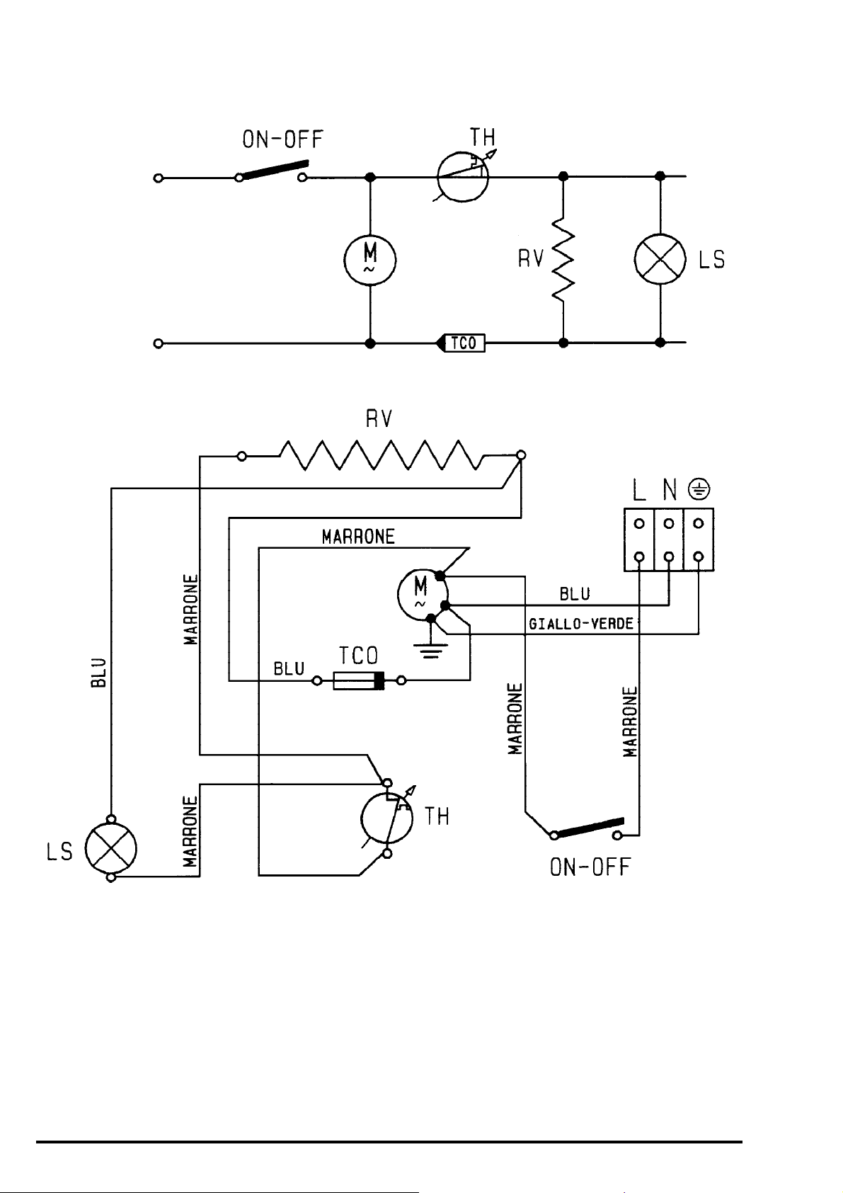
SCHEMA ELETTRICO / ELECTRICAL DIAGRAM / SCHALTPLAN
SCHEDA TECNICA 98050
SCHEMA ELECTRIQUE / SCHEMA ELECTRICO
FP / FP-A / FP-EC
L
N
COLORI COLOURS FARBEN COULEURS COLORES
Blu Blue Blau Bleu Azul
Giallo-verde Yellow-green Gelb-Grün Jaune-vert Amarillo-verde
Marrone Brown Braun Marron Castano
LEGENDA LEGEND ZEICHENERKLÄRUNG LEGENDE LEGENDA
LS Spia acceso/spento On/off warning light An/Aus Kontrolleuchte Voyant marche/arrêt Testigo abierto/cerrado
M Motore cesto Basket motor Korbmotor Moteur panier Motor cesto
ON-OFF Interruttore generale Main switch Hauptschalter Interrupteur générale Interruptor general
RV Resistenza Heating element Heizkörper Elément chauffante Resistencia
TCO Fusiblile termico Thermal fuse Thermische Sicherung Fusible thermique Fusible térmico
TH Termostato Thermostat Thermostat Thermostat Termostato
2
Page 3

SCHEMA ELETTRICO / ELECTRICAL DIAGRAM / SCHALTPLAN
SCHEDA TECNICA 98050
SCHEMA ELECTRIQUE / SCHEMA ELECTRICO
FP / FP-A / FP-EC (Ex:B)
ON-OFF
TH
M
M
TCO
RV
LS
RV
TCO
TH
ON-OFF
LS
COLORI COLOURS FARBEN COULEURS COLORES
Blu Blue Blau Bleu Azul
Giallo-verde Yellow-green Gelb-Grün Jaune-vert Amarillo-verde
Marrone Brown Braun Marron Castano
LEGENDA LEGEND ZEICHENERKLÄRUNG LEGENDE LEGENDA
LS Spia acceso/spento On/off warning light An/Aus Kontrolleuchte Voyant marche/arrêt Testigo abierto/cerrado
M Motore cesto Basket motor Korbmotor Moteur panier Motor cesto
ON-OFF Interruttore generale Main switch Hauptschalter Interrupteur générale Interruptor general
RV Resistenza Heating element Heizkörper Elément chauffante Resistencia
TCO Fusiblile termico Thermal fuse Thermische Sicherung Fusible thermique Fusible térmico
TH Termostato Thermostat Thermostat Thermostat Termostato
3
Page 4

ACCESSIBILITA' / ACCESSIBILITY / ZUGÄNGLICHKEIT
SCHEDA TECNICA 98050
ACCESSIBILITE' / ACCESIBILIDAD
1) ELECTRICAL COMPONENTS
1.1 To gain access to inside components, remove
the bottom cover by unsrewing its two screws
2) ALUMINIUM POT REPLACEMENT
2.1 Remove the bottom cover as descibed
above
2.2 Unscrew the two screws "B"
2.3 Disconnect all terminals
2.4 Pull out the oil drainage pipe
2.5 Remove the bottom frame by pressing on
the tabs "F"
2.6 Pull out the condensate water drainage tray
2.7 Unscrew the screw "C"
2.8 Unscrew the screw "D"
2.9 Remove the lid
2.9.1 Remove the aluminum pot by pulling it from
above
4
Page 5

3) CASING REPLACEMENT
SCHEDA TECNICA 98050
3.1 After having carried out operation as
above, unscrew screws "E" and "A" to
free the casing
TECHNICAL INFORMATIONS
FRYERS
Fryers FP series
Coupling of thermostat gear-slide of FP series.
To re-assembly the two components, after having executed a riparation, follow the below procedure:
1) - Position the thermostat at the maximum temperature by turning its shaft completely anticlockwise (See
figure.1).
2) - The gear must be positioned as shown in figure 2.
3) - Now move the temperature slide of the fryer on 190°C (maximum temperature).
4) - Insert the tooth "A" (see fig. 2) in the first slot of the slide (that one which corresponds to the side of 190°).
5) - Then mount the bottom cover and close the appliance.
Fig. 1 Fig. 2
Position of the thermostat tab
when set at maximum temperature
A
Ingranaggio
5
 Loading...