

Page 1
RADIANT HEATER
SAFETY INSTRUCTIONS
(KEEP IN A SAFE PLACE)
SPARE COPIES OF THIS LEAFLET CAN BE OBTAINED FROM YOUR DEALER
U.K. AGENT:
De’Longhi Ltd.
15/16 Bridle Close - Stewarts Road
Finedon Industrial Estate
Wellingborough
Ph 0933 442040
X-Press 1-03-2002 11:54 Pagina 1
Page 2
Heater safety instruction. (Keep in a safe place).
Spare copies of this leaflet can be obtained from your dealer.
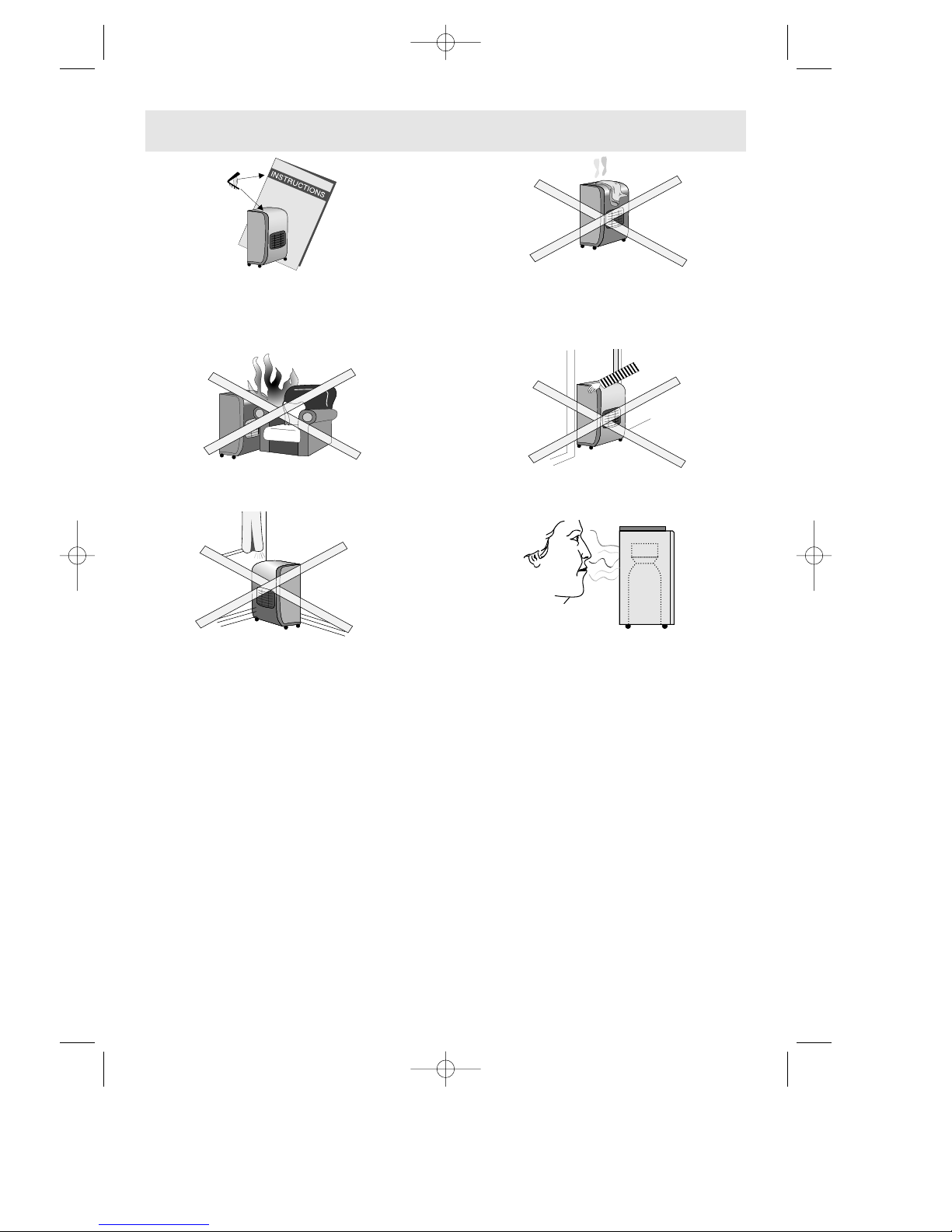
1 Always use heater in accordance with
instructions supplied with each heater.
Keep Instructions in a safe place.
2 Do not place clothes or other materials
on the heater, as apart from the danger
of fire their presence could affect the efficient working of the appliance.
3 Do not position heater close to chairs and
fabrics.
4 Do not move heater from room to room
when it is lit.
5 Do not position heater alongside a wall or
near curtains, etc. Always face heater
towards centre of room.
Special care should be taken if the heater is on a surface where it can move or
twist on its wheels or castors if knocked by
a child or dog, etc.
6 A LEAK WILL SMELL
If a leak is suspected, turn the gas off at
cylinder. Do not disconnect the regulator.
Extinguish all naked lights. Check all connections. Slowly turn the gas on and brush
the connections with soapy water or liquid
detergent - a gas leak will form bubbles. If
a leak is found turn the gas off and inform
your Dealer. DO NOT use the heater again
until it has been inspected by your Dealer.
If the cylinder valve appears to be
leaking when turned off, refit the Black
Branch Cap or Orange Valve Cap.
- This appliance MUST NOT be used in basements, high rise flats, bathrooms or bedrooms
and in rooms having volume less than 15m
3
(30m3in living rooms) for three burner models,
18m
3
(36m3in living rooms) for two burner models.
- Be sure installation is complying to local standard.
- Do not install the appliance in a room which might contain gas, oil or sulphur, or near sources of heat.
- The appliance should not be used at altitudes exceeding 1500 m. as the analyzer may be
triggered off causing the appliance to switch off unexpectedly.
Ventilation
Use only in a well ventilated room (see page 4 of these instructions, where applicable).
Do not change cylinders in the presence of naked lights.
2
X-Press 1-03-2002 11:54 Pagina 2
Page 3
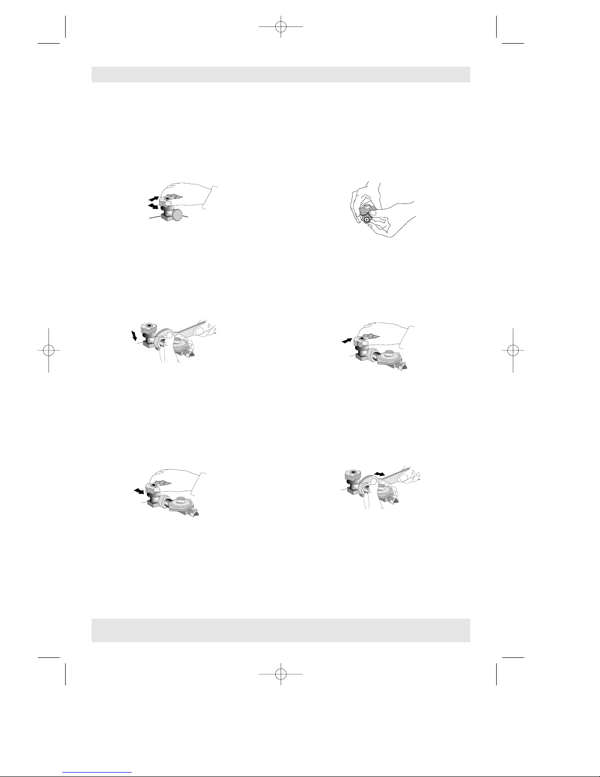
SCREW ON REGULATOR
1. Connecting cylinder and turning the gas on
a Make sure that the black plastic cap is
screwed onto outlet of full cylinder.
Ensure valve operates freely by turning
anticlockwise to open and clockwise to
close. Firmly close valve by turning
handwheel clockwise. Remove black
plastic cap from valve outlet and store in
a safe place for future use.
b Make sure black neoprene washer is in
place on the regulator iniet. Regularly
examine, and if unduly compressed or
damaged, replace. Do not replace with
red branch cap washer.
c Support regulator, screw union nut onto
cylinder valve by turning nut anti-clockwise
(left-hand thread). Tighten just over hand
tight using Calor Spanner. After fitting the
regulator it may have assumed a position
out of the horizontal. This is not important.
Do not attempt to twist regulator.
d Place cylinder in cabinet so that the cylin-
der valve is facing into the compartment.
Open cylinder valve by turning
handwheel anticlockwise. Make sure that
all connections are gas tight, by brushing
with soapy water or liquid detergent (a
gas leak will form bubbles). Now refer to
the lighting instructions on the heater.
a Close cylinder valve by turning
handwheel clockwise. Check that the
heating elements and pilot are out.
b Open back the appliance, remove cylinder
and place close to heater (do not strain
hose). Support regulator, use a Calor
Spanner to disconnect regulator/ cylinder
valve union by turning nut clockwise (left-
hand thread). Care must be taken to ensure that the outlet connection on the regulator is not damaged or strained. Screw black
plastic cap onto valve outlet. Place empty
cylinder in a safe place.
2. Turning off and disconnecting the cylinder
Where the screw on regulator is used in conjuction with a switch-on adaptor refer to
instructions supplied with adaptor.
3
Gas Bottle
Gas Bottle with 15 kg of maximum capacity can be installed. Changing of gas bottle must not
be carried out in the presence of a naked flame. Use the gas bottle always in upright position.
If a screw on regulator is used ensure that the rgulator washer is present and in good condition - replace if any doubt. To place the bottle in position, remove the rear panel which faces
the inside during transport, by unfastening the screws; than put the bottle in position and
replace the panel. Do not turn the bottle upside down to use completely its content.
X-Press 1-03-2002 11:54 Pagina 3
Page 4

4
MODEL NO. 182H SWITCH ON REGULATOR (Suitable for Calor Switch-on 21 mm Gas Bottle)
1. Connecting the cylinder
aRotate the plastic cap on the cylinder
valve until the arrow points out through
the gap in the valve shroud.
b Pull the lanyard out, then upwards. The
cap will lift off the valve. Do not use
tools. Leave the cap hanging down from
the valve while the cylinder is in use.
c Ensure that the point of the switch is
pointing down. Place the regulator
down over the cylinder valve.
d Turn the switch clockwise so that it points
to the left (the OFF position). the regulator is now secured gas-tight to the valve,
which is still closed OFF. There will be a
“click” into the lock-on position.
2. Turning the gas on and off
a To turn the gas on, turn the switch clockwi-
se so that it points upwards. The cylinder
valve is now open and the gas is on.
b Turn the switch anti-clockwise to the left
and the gas is off. Do not touch the centre button.
3. Disconnecting the cylinder
There are 2 steps in disconnecting the regulator
a depress the centre button of the black
switch.
b Keeping the button in the depressed
position, turn the black switch anticlockwise until it points downwarnds. The
regulator can be lifted off the valve.
Never turn the switch to the “disconnect” position when the burner is alight. Wait until the burner and pilot go out; at this point turn the switch to the “disconnect” position.
Always replace the orange safety cap on the cylinder valve.
X-Press 1-03-2002 11:54 Pagina 4
Page 5

5
MODEL NO. 541101 REGULATOR
Connecting the cylinder
aTurn the orange cap so that the arrow is
pointing to the gap in the shroud.
b Remove the orange safety cap by pul-
ling the lanyard out, then up. Do not use
tools. Leave the cap hanging.
cCheck that the black sealing washer is
fitted inside the cylinder valve. Place the
regulator down over the valve until the
lever of the coupling engages with an
audible click.
d When gas is required, turn the switch
anticlockwise to the ON (6 o’clock) position.
Disconnecting the cylinder
a Turn the switch clockwise to the OFF posi-
tion.
bWAIT until the burner and pilot light have
gone out.
IF THE FLAME DOES NOT GO OUT - TURN
THE SWITCH BACK TO “ON”, LEAVE THE
APPLIANCE ALIGHT, AND CALL YOUR
GAS SUPPLIER.
c Never lift the disconnect lever whilst tur-
ning the ON/OFF switch.
d With the regulator switch in the OFF posi-
tion lift the disconnect lever and lift the
regulator from the cylinder valve.
e REPLACE the orange safety cap onto the
empty cylinder, or part full cylinder if not
in use.
X-Press 1-03-2002 11:54 Pagina 5
Page 6

6
GENERAL SAFETY INSTRUCTIONS
Cylinder valve
If heater does not completely extinguish, including pilot, when gas is turned off, do not remove regulator. Return valve to open position and leave heater alight, which is perfectly safe,
until attended to by the gas supplier.
Regulators, hoses and clips
Check that tubing is completely over the nozzles at each end of the
tubing and that it is held firmly in place by hose clips. Examine flexible
tubing regularly and get your dealer to fit new tubing 400 mm long
complying to local standard, if perished, worn or damaged. In any
case replace the tube every 5 years. L.P.G. attacks natural rubber - use
only tubing to B.S. 3212 Type 2 supplied by your dealer.
When connecting the regulator to the container avoid undue twisting of the flexible hose.
A regulator to B.S. 3016 set at 28 mbar (11,2 in w.g.) for butane must be connected to the
appliance with the above tubing, using suitable hose clips.
Ventilation
Use only in a well ventilated room.
Adequate ventilation must be provided in rooms in which
the heater is used. This ensures removal of the products of
combustion and allows the entry of replacement air.
Adequate ventilation should considerably reduce the
possibility of condensation occurring.
The following table shows the smallest size of room suitable for the heater and the ventilation which must be provided. The heater may be used for
short periods in smaller rooms.
Maintenance
Ensure that the heater is kept free of dust. When not in use the heater should be covered and
stored in a dust-free place. Stains on the exterior should be removed with a soapy solution
when the heater is cold. Dry with a polishing cloth do not use abrasive cleaners which will
damage the paint finishes. Refer any major maintenance to your Local Authorised Dealer
Major servicing should be carried out every 2 - 3 years. If in doubt refer to your authorised
dealer.
Safety guard:
The guard on this appliance conforms to the requirements of B.S. 1945: 1971 and satisfies the
heater appliances (fireguards) regulations. The guard is to prevent risk of fire or injury from
burns and no part of it should be permanently removed.
It does not give full protection for young children or the infirm.
Positioning the heater:
DO NOT PLACE clothes or other materials on the heater.
DO NOT POSITION heater close to chairs or fabrics.
DO NOT MOVE the heater across the room when lit.
DO NOT POSITION the heater alongside a wall or near curtains etc.
ALWAYS face the heater towards the centre of the room.
Type Category Max. Input Low Input Gas pressure
Gas combustion
air-quantity
See rating label
This appliance is designed to operate with Butane, propane or mix. LPG at nominal pressure: 28÷30 mbar
Kw g/h
4,2 305
Kw g/h
1,50 109
28÷30 mbar 8,4 m
3
/h
Room Size Room Aperture
42 m
3
105 cm
2
X-Press 1-03-2002 11:54 Pagina 6
Page 7

7
Operating instructions:
The gas is turned on and off at the cylinder. The heat input and spark for ignition are controlled by the knob situated on the top right hand side.
Lighting the heater:
1 Turn on the gas cylinder by either:
a Turning the cylinder valve anti-clockwise where a screwed cylinder connection is used.
or b Turn the black switch clockwise so that it points towards the flame
symbol where a switch-on system is used (Model No. 182H).
or c Turn the switch anti-clockwise to the ON (60’ clock) position (Model
No. 541101).
2 Fully depress the grey button ( ) for 10 seconds and push 2 or 3 times the red button ( )
(if pilot flame does not ignite, repeat the above mentioned operations). Continue to fully
depress the grey button for a further 20 seconds to allow the thermocouple probe to heat
up, then release.
3 Turn the thermostat knob anticlockwise on position 6 and allow all three burners to heat
up.
When the room has reached the desired temperature, slowly rotate the thermostat knob
clockwise until the side burners turn off.
In this way the appliance will maintain the desired room temperature automatically chan-
ging from maximum input (❑❑❑)to low input (❑) and viceversa.
Turning off the heater:
The heater will only be totally “OFF” when the supply of gas from the cylinder has been turned
“OFF” after use the appliance must be turned “OFF” at the valve.
a Turning the cylinder valve clockwise where a screwed connection is used.
or b Turning the black switch anti-clockwise so that it points in the horizon-
tal position if a switch-on system is used (Model No. 182H).
or c Turn the switch clockwise to the OFF position (Model No. 541101).
DO NOT ATTEMPT to relight until FIVE minutes have elapsed.
Warning for switch-on system:
when the heat is alight, never turn the switch on the cylinder to the disconnect position. Wait
until heater and pilot go out, then and only then, should the switch be turned to the disconnect position if the cylinder requires changing.
FOR MODEL No. 182H
If the black switch of your regulator is fitted with a centre button this
must be depressed before turning to the disconnect position.
FOR MODEL No. 541101
With the regulator switch in the OFF position, lift the disconnect lever and lift
the regulator from the cylinder valve.
It is dangerous to switch to the disconnect position when the heater is alight.
ON
OFF
DISCONNECT
573627/10.95
X-Press 1-03-2002 11:54 Pagina 7
 Loading...