

Page 1

R410A
Page 2

1
.
1.1 Rimozione panello oscilante......................... 03 1.1 Remove oscillating panel............................... 03
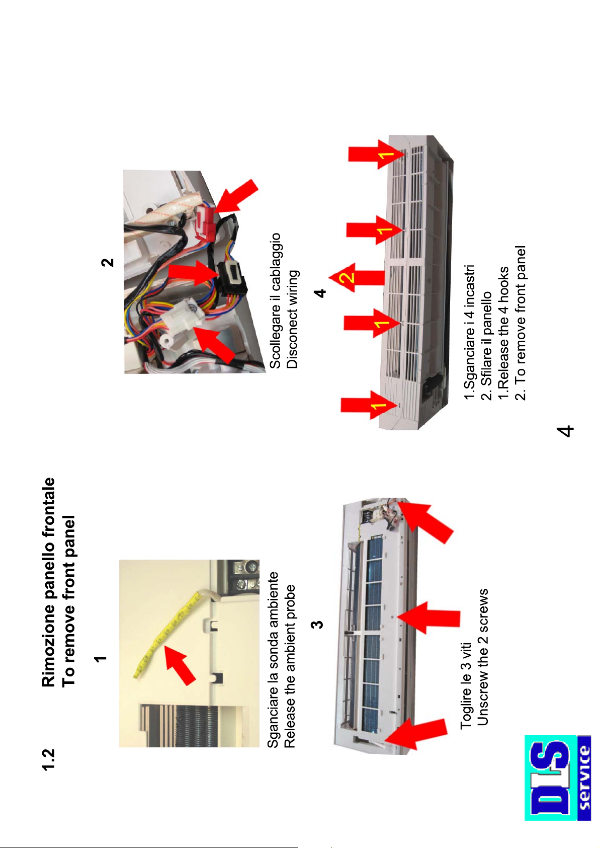
1.2 Rimozione panello frontale........................... 04 1.2 Remove front panel....................................... 04
CONTENUTO
1. ACCESSIBILITA' UNITA' INERNA.............. 02 1. ACCESSIBILITY THE INDOOR UNIT............02
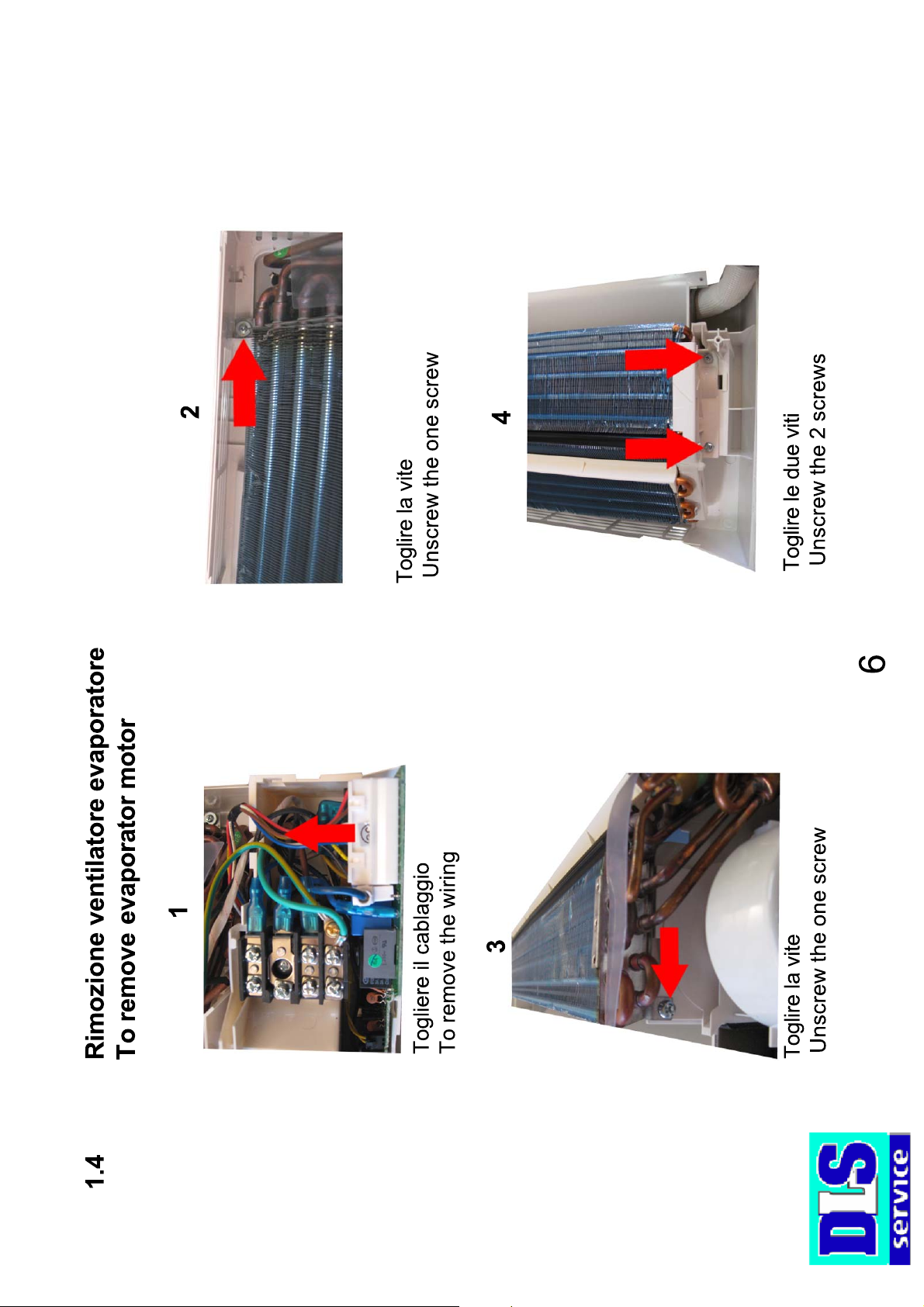
1.4 Rimozione ventilatore evaporatore............... 06 1.4 Remove evaporator motor............................. 06
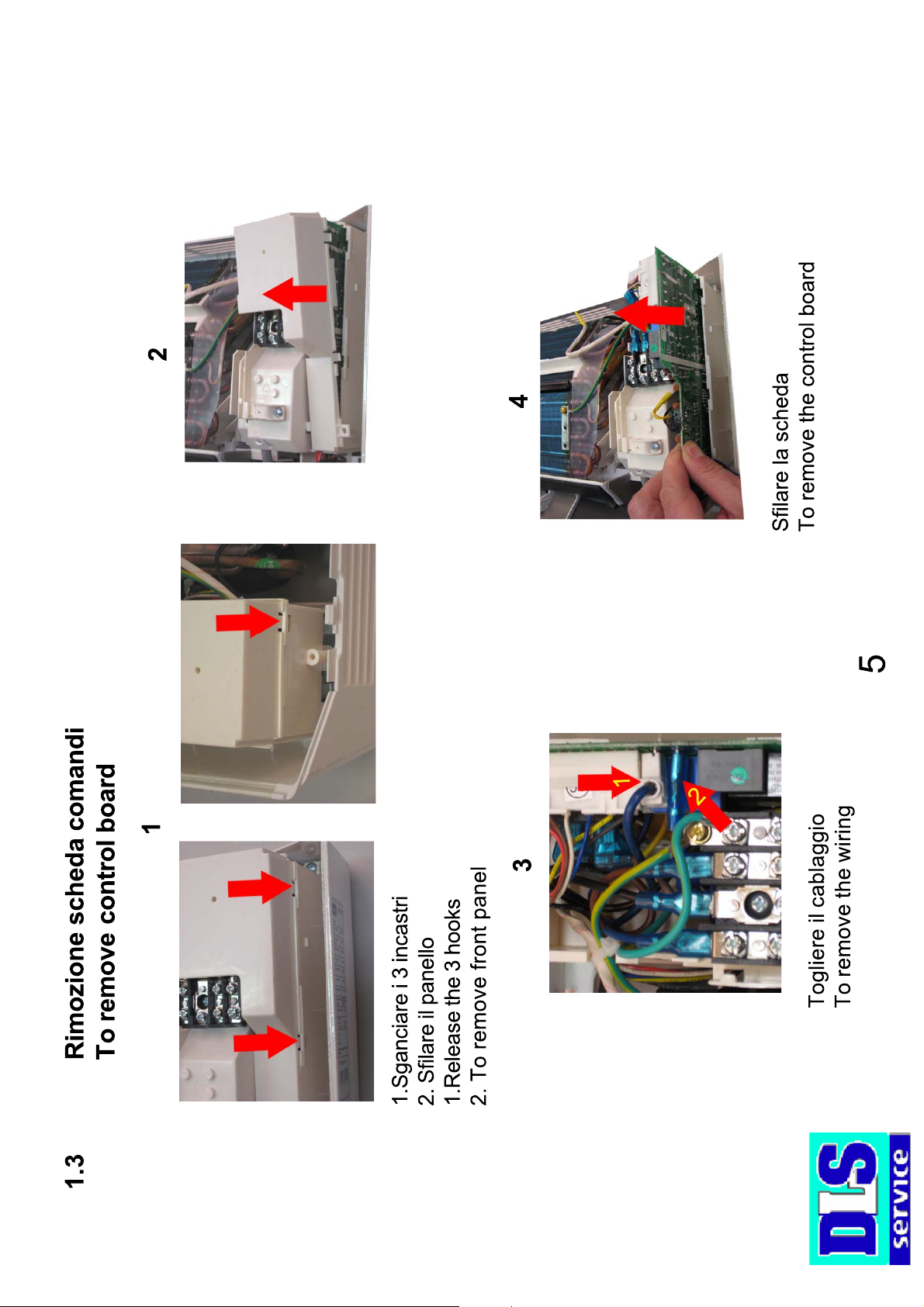
1.3 Rimozione scheda comandi.......................... 05 1.3 Remove control board................................... 05
ACCESSIBILITA' UNUITA' ESTERNA......... 07 ACCESSIBILITY THE OUTDOOR UNIT........ 07
1.5 Rimozione scheda potenza.......................... 08 1.5 Remove power board.................................... 08
1.6 Rimozione ventilatore condensatore............ 09 1.6 Remove condenser motor............................. 09
2. SCHEDA TECNICA..................................... 10 2. TECNICAL DATA SHEET............................. 10
2.1 Schemi elettrici............................................ 11 2.1 Wiring diagram............................................. 11
3. CIRCUITO FRIGORIFERO.......................... 14 3. REFRIGERATION CYCLE DIAGRAM.......... 14
4. CODICI ERRORI......................................... 16 4. ERRORS CODE........................................... 16
5. CONNESSIONE ATTACCHI RAPIDI........... 19 5. QUICK CONECTION.................................... 19
Page 3

2
ACCESSIBILITY
1. ACCESSIBILITA’
Page 4

Page 5
Page 6
Page 7
Page 8

6
1.Togliere la vite
1.To remove the screw
1.To remove the motor
.1.Sfilare il motore
7
1.4
5
1.To remove the 2 screws
.1.Togliere le 2 viti
2.Togliere il coperchio
78
2.Alzare la ventola e sfilarla
1.To raise battery the evaporator
2.To remove front panel
.1.Alzare batteria l'evaporatore
2.To raise the fan and to parade it
Page 9

3
5
1.Togliere le 2 viti
2. Sollevare il coperchio
1.Unscrew the 2 screws
2.To remove the panel
Togliere le 4 viti
Unscrew the 4 screws
8
2
Togliere la vite
Unscrew the one screw
1
To Remove power board
1.5 Rimozione scheda potenza
Togliere le 2 viti
Unscrew the 2 screws
4
Togliere la vite
Unscrew the one screw
Page 10

3
Sganciare i 3 incastri
Release the 3 hooks
4
2
9
Togliere le 4 viti
To remove the 4 screws
1
To Remove condenser motor
Togliere la vite
Unscrew the one screw
Togliere le 2 viti
Unscrew the 2 screws
3
Togliere il dado
To remove the nut
1.6 Rimozione ventilatore condensatore
Page 11

10
TECNICAL DATA
SHEET
2. SCHEDA TECNICA
Page 12

Unità interna / indoor unit
11
2.1 Schema elettrico / Wiring diagram PLS110 / PLS120
Page 13

Unità interna / Indoor unit
12
2.1 Schema elettrico / Wiring diagram PLS130
Page 14

Unità esterna / Autdoor unit
13
2.1 Schema elettrico / Wiring diagram PLSI / 120 / 130
Page 15

14
REFRIGERATION
CYCLE DIAGRAM
3. CIRCUITO FRIGORIFERO
Page 16

OUTODOOR UNIT
EER
HEAT
EXCHANGE
(CONDENSER)
COOLING
REVERSING
VALVE
COMPRESSOR
HEATING
INDOOR UNIT
LIQUID
SIDE
VALVE
HEAT
EXCHANGE
(EVAPORATOR)
GAS SIDE
ACCUMU
LATOR
VALVE
15
3.1
Page 17

CODES ERROR
16
4. CODICI ERRORE
Page 18

Errore
Protezione alte temperature in cool
Protezione aria fredda
Codice
E8(*)
E9(*)F1F2
Sensore ambiente unità esterna
Sensore tubo unità interna
Sensore ambiente unità esterna
F3(*)
Sensore tubo unità esterna
Sensore di mandata unità esterna
F4(*)
F5(*)
Error
High temperature protection only cool
Code
E8(*)
Protection against cold air
Indoor unit room sensor disconnected
indoor unit pipe sensor disconnected
Outdoor unit ambient sensor disconnected
E9(*)F1F2
F3(*)
Outdoor unit pipe sensor diconnected
Outdoor unit delivery line sensor
short-circuited/disconnected
F4(*)
F5(*)
17
88
Codici errori scheda comandi solo per modello DC INVERTER
Errore
Protezione alta temperatura solo HP
Protezione sbrinamento
Codice
E1(*)
E2(*)
Protezione basse pressioni
Protezione scarico compressore
Protezione sovraccarico corrente
E3(*)
E4(*)
E5(*)
Malfuzionamento comunicazione
Conflitto MODE
E6(*)
E7(*)
(*) Codici di allarme validi solo per modello DC INVERTER.
88
Error
High temperature protection only HP
Code
E1(*)
Defrost protection
Low pressure protection
Compressor gas discharge protection
Current overload protection
E2(*)
E3(*)
E4(*)
E5(*)
Communication malfunction
MODE conflict
E6(*)
E7(*)
(*) Alarm codes valid only for DC INVERTER model
4.1 Codes error control board only for DC INVERTER model
Page 19

Page 20

19
RAPIDI
QUICK CONECTION
5. CONNESSIONE ATTACCHI
Page 21

Locating pin Clip
Take off the clip from the push-pull
connector ( male plug )
Press the handle downwards
and remove the panel
The user must remove the
temperproof closures.
Insert the push-pull connector (male plug) into the
female socket and re-position the fixing cable at the
The locating pin must be facing downwards.
same time.
20
5.1
Screw
Remove one screw
Connector
Pull the ferrule inwards as indicated
by the arrow.
remove the cover protecting the
connections by sli-ding back the
lockout.
Before carrying out the connection
Page 22

Terminal
Cable clamp
Connect the cable terminal
Secure the cable tothe appliance using
the clamping device provided
21
Mount the large handle
5.
It is difficult to press the clip down
fully if the fixing cable has not been
properly re-positioned.
After fully closing the push-pull connection,
insert the shear pin into the relative hole
shown.
Rotate the clip and press it down as far as it
will go.
 Loading...