

Page 1
ELECTRIC HEATING CONVECTOR
Instructions booklet
Please keep in a safe place as you may need to refer to them at a later date
5713003700 11-06-2002 14:03 Pagina 1
Page 2
2
1
2
3
4
5
6
7
8
9
10
11
12
12
1
3
13
1
4
14
1
5
15
1
6
16
1
7
17
18
18
1
9
19
20
20
2
1
21
22
22
2
3
23
24
24
1
2
3
4
5
6
7
8
9
1
0
10
1
1
11
12
12
13
13
1
4
14
1
5
15
1
6
16
1
7
17
1
8
18
1
9
19
2
0
20
2
1
21
22
22
2
3
23
24
24
Fig.1
411 mm
275 mm (mi
n
.
)
600 mm (min.)430 mm (min.)
A
A
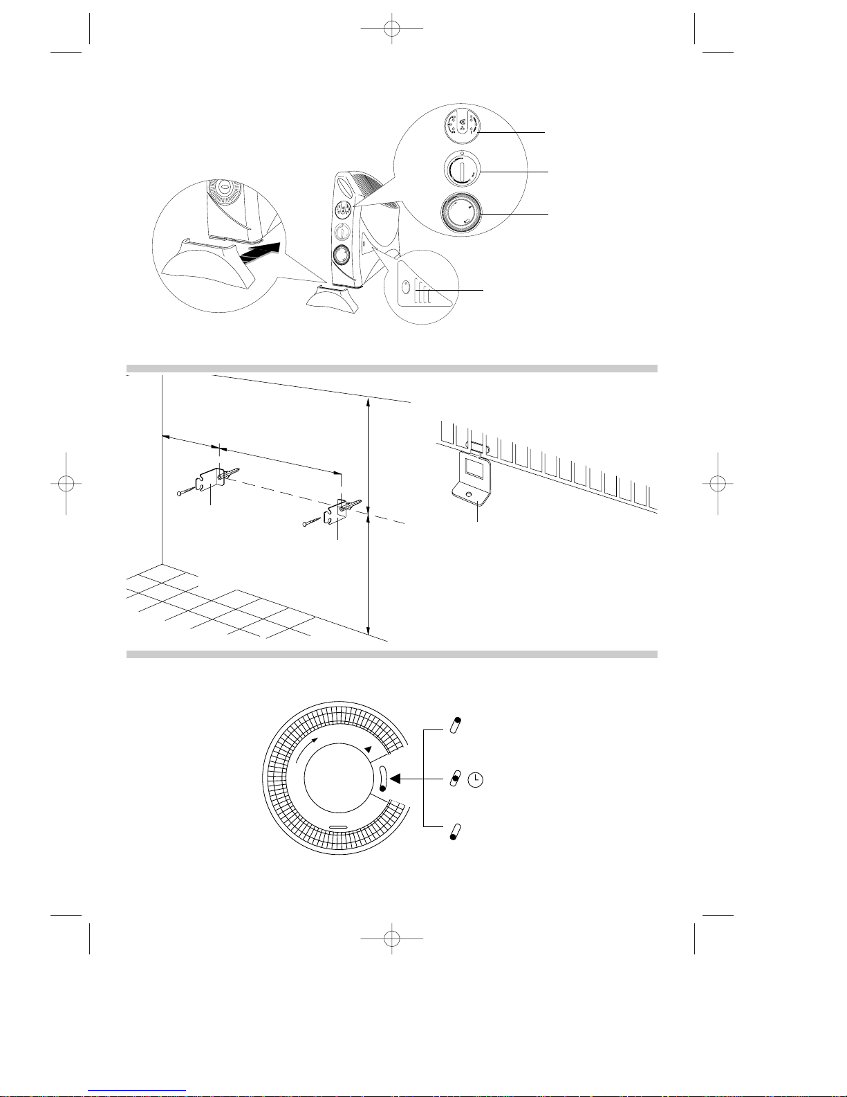
Fig.2
Power selector
Timer
Thermostat dial
Turbo fan switch
B
Fig.3
1
0
Fig.4
MANUAL (Timer override)
TIMED OPERATION
HEATER OFF
5713003700 11-06-2002 14:03 Pagina 2
Page 3
3
GENERAL INSTRUCTIONS
Remove the heater from the packaging. Check that neither the heater nor the power cable has been damaged during transport.
Do not operate the heater if damaged.
Your convector is suitable for either freestanding or wall mounting usage. Do not assemble the feet if wall mounting.
ASSEMBLING THE FEET
To fit the feet to the appliance, proceed as follows:
Insert the foot into the slot at the side and push it in all the way until it hooks onto the two teeth (Fig. 1).
WALL-MOUNTING
IMPORTANT:
Before drilling into any wall ensure no electrical cables are present in the area.
In order to wall mount your convector please proceed as follows:
1. Fix two brackets “A” following carefully the dimensions as indicated in figure 2. Use a 6 mm masonry drill and suitable wall
plugs and 2 x No 8 screws (minimum length 25 mm).
2. Hang the convector on the two brackets fixed to the wall and insert metal brackets “B” into the bottom rear section of the
base of the convector as indicated in figure 3, one at each end.
Mark the positions for fixing these brackets to the wall.
This bracket when fixed retains the base of the convector in a fixed position, preventing removal.
3. Remove the convector heater from the hanging brackets and drill the wall for 2 x suitable wall plugs and insert them.
4. Fit the convector to the 2 brackets “A”. Insert Brackets “B” to the convector base and fix brackets “B” to the wall plugs by
means of 2 x No 8 screws ( minimum length 25 mm).
Your convector is now wall mounted.
The appliances should not be installed directly under a wall power socket.
Do not use your heater in a bathroom.
The appliance should not be installed immediately below a permanent mains outlet.
Position the appliance so that the plug and the socket can be easily reached even after installation.
ELECTRICAL CONNECTION
- Before plugging the appliance into the mains, check that your supply voltage is the same as that shown on the rating plate
of the appliance.
- If using more than one appliance at a time, it is important to ensure that the ring main is adequate to cope with the power
requirements.
- This appliance complies with EEC Directive 89/336 relating to electromagnetic compatibility.
The wires in the mains lead are coloured in accordance
with the following code:
Blue: Neutral
Brown: Live
As the colours of the wires in the mains lead may not correspond
with the coloured markings identifying the terminals in your plug,
proceed as follows:
The blue wire must be connected to the terminal marked with the
letter N or coloured black.
The brown wire must be connected to the terminal marked with the
letter L or coloured red.
I
f you have a 3-pins plug, do not connect any wire to the “earth”
terminal.
ELECTRICAL CONNECTION (U.K. ONLY)
A) If your appliance comes fitted with a plug, it will incorporate a
13 Amp fuse. If it does not fit your socket, the plug should be
cut off from the mains lead, and an appropriate plug fitted, as
below.
WARNING: Very carefully dispose of the cut off plug after removing
the fuse: do not insert in a 13 Amp socket elsewhere in the house
as this could cause a shock hazard.
With alternative plugs not incorporating a fuse, the circuit
must be protected by a 15 Amp fuse.
If the plug is a moulded-on type, the fuse cover must be refitted when changing the fuse using a 13 Amp Asta approved
fuse to BS 1362. In the event of losing the fuse cover, the
plug must NOT be used until a replacement fuse cover can
be obtained from your nearest electrical dealer. The colour of
the correct replacement fuse cover is that as marked on the
base of the plug.
B) If your appliance is not fitted with a plug, please follow the
instructions provided below:
5713003700 11-06-2002 14:03 Pagina 3
Page 4

This heater has ECC (electronic climate control) which automatically monitors and selects the ideal power to maintain a
chosen temperature.
HOW TO USE IT
Insert the plug into the mains socket and switch on, pressing the button (fig. 5) one or more times, to select your operating heating power as follows:
4
Press once
Maximum power
Press twice
Medium power
Press three times
Minimum power
Press four times
OFF
A
B
C
D
If maximum power has been selected, adjust the thermostat dial (fig. 6) to the desired comfort
temperature from (5°C) and MAX (35°C).
If the selected temperature is higher than the actual room temperature, the appliance will start
automatically and rapidly heat the room until it reaches the selected temperature. The unit will
automatically maintain the temperature at a constant level by cycling between max power, med
power and min power as it approaches the selected comfort temperature (see fig. 7).
Maximum power example (fig. 7)
MAX
MAX MED MIN OFF
Cycles between
Display LEDs
*
If the room temperature exceeds the selected temperature level, the appliance will switch off (fig. 5D). The heater will
switch back on automatically when the room temperature falls below the selected temperature level.
If medium power level has been selected using the button, and the thermostat set, the heater will modulate between
the medium and minimum power levels. As with the maximum power setting, if the room temperature exceeds the selected temperature, the appliance will switch off, and then on again when the temperature falls.
(For models with timer, ensure that the switch on the timer dial (fig.4) is in position
1, manual.
NOTE: if the timer switch is at the
0 position (fig.4), the heater is off and will not operate).
Fig. 6
The LEDs on
the left hand
side show you
the power
selected
The LEDs on the right
hand side show you
the actual power the
heater is operating at.
Important: when the
heater has been set for
timed operation and is
in a standby period (i.e
waiting to come on),
the LEDs on the right
hand side will light up
and go out intermittently. (See timer instructions).
Button
Fig. 5
Selected power
Power used
5713003700 11-06-2002 14:03 Pagina 4
Page 5

Frost stat function
Press the button, it is recommended to select maximum power level.
Set the thermostat dial to the “ “ position (fig. 6).
When set in this way, the appliance will switch on automatically only if the room temperature falls below 5°C, to prevent
freezing, at minimum energy consumption.
This function is not guaranteed in the event of power failures, even if lasting just a few seconds.
Models with turbo fan boost (see fig. 1)
A number of models have a turbo fan boost for even more rapid and uniform heating. To use this function, press the
switch on the fan grill.
Cool air ventilation
To operate the fan only for “cool air” ventilation, ensure that ECC is off and turn the thermostat to the maximum then
press the switch on the fan grill.
5
*
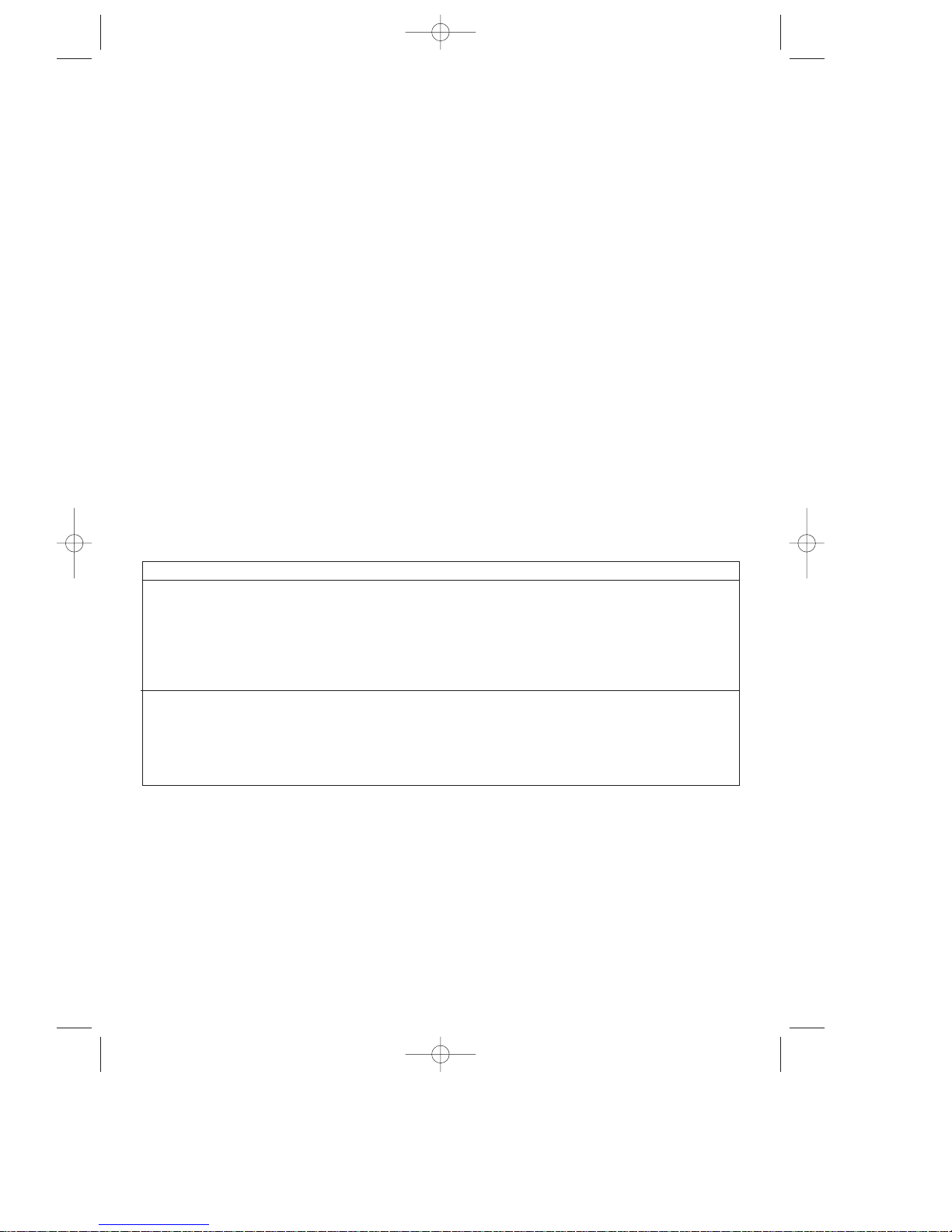
USING THE TIMER
If you wish to use the timer, position the switch in the
middle position .
1= Manual (timer override)
= Timed operation
0 = Heater off
SETTING THE CORRECT TIME
Check the time on your watch. If for example it is 4.00
pm. (16.00), turn the dial in a clockwise direction until
the number 16 is lined up with the triangular pointer .
21
20
19
16
pointer
N.B.: Never turn the dial in an anti-clockwise direction!
The timer is in effect, an electric clock and works only
if the plug is connected to the power supply.
Whenever the plug is disconnected or there is a
power failure, the clock must be re-set.
TO PROGRAM THE TIMER
1) Set the operating times by pushing out the
notches on the dial corresponding to the period
required (each notch represents 15 mins.)
2) Make sure that the timer indicates the correct
time (see instructions on setting the correct time).
3) Select the desired function as shown in the table
on page 5.
21
20
19
16
operating time
Once programmed in this way, the appliance will
repeat the pre-established program every day, if the
selector is in the position.
TIMER OVERRIDE
If you wish to override the timer settings, push the
timer switch to position 1 (fig.4)
manual (timer over-
ride).
To return to timed operation push the switch
back to the middle position (fig.4)
1
0
5713003700 11-06-2002 14:03 Pagina 5
Page 6

MAINTENANCE
Before carrying out any maintenance, unplug the heater from the mains and wait for it to cool. The convector requires no
particular maintenance. It is sufficient to remove the dust with a soft, dry cloth. Never use abrasive powders or solvents. If
necessary remove concentrated areas of dirt with a vacuum cleaner.
WARNINGS
ATTENTION: in order to avoid any danger caused by an accidental resetting of the safety system, this appliance must
not be powered through an external timer.
- Do not make use of this heater in the immediate proximity of bathroom, washbasins or swimming pools..
- Never use the heater to dry laundry.
- Never place the power cable on top of the heater while it is hot.
- Only use the heater in an upright position.
- Do not block the hot-air outlet grilles or the intake grille located on the bottom of the heater.
- The heater must be positioned at least 50cm from furniture or other objects.
- If the power cable is damaged, it must be replaced by the manufacturer or an authorised technical service centre.
- Do not use this appliance in rooms which have an area smaller than 4m2. We recommend that you do not place the
heater in a draught, because strong draughts of air may adversely affect the equipment’s operational efficiency.
- The heater must never be placed immediately under a fixed mains socket.
- IMPORTANT: Never for any reason cover the appliance during operation as this could lead to dangerous
overheating.
-A safety device intervenes and turns off the appliance in the event of overheating or because the appliance is positioned in a strong draught of air. To reactivate it, remove the plug from the electrical outlet, allow the appliance to
cool (about 5’), remove the cause of the overheating/draught and then reconnect the appliance to the mains and
turn it back on.
-A number of models have a special device to cut off current if the unit is overturned, placed at an angle or knocked,
a sound alarm indicates this problem.
- The use of an extension lead is not recommended, as overheating of the extension lead may occur during the operation of the heater.
- As with any electrical appliance, whilst the instructions aim to cover as many eventualities as possible, caution and
common sense should be applied when operating your appliance, particularly in the vicinity of young children.
6
5713003700 11-06-2002 14:03 Pagina 6
Page 7

5713003700/06.02
5713003700 11-06-2002 14:03 Pagina 7
 Loading...