

DeLonghi GWHD18A1NK3EA Service Manual
Room Air Conditioner
SPLIT TYPE ROOM AIR CONDITIONER
Prior to installation, this air-conditioning unit must
be submitted for approval by the utility service
which provides electricity (EN 61000-3 Norm).
MODEL:
GWHD18A1NK3EA
(Applied to new Refrigerant R-410A)
-BEFORE SERVICING THE UNIT, READ THE SAFETY PRECAUTIONS IN THIS MANUAL.
-ONLY FOR AUTHORIZED SERVICE PERSONNEL.
SERVICE MANUAL
CAUTION

Air Conditioner Service Manual
TABLE OF CONTENTS
Safety Precautions ...........................................................................................................................1
Dimensions .......................................................................................................................................6
Product Specifications ....................................................................................................................8
Installation.........................................................................................................................................9
Flaring work and connection of piping.........................................................................................11
Connecting the cable between indoor unit and outdoor unit.....................................................16
Checking the drainage and forming the pipings .........................................................................18
Air purging ......................................................................................................................................19
Test running ....................................................................................................................................21
Functions.........................................................................................................................................22
Operation.........................................................................................................................................24
Disassembly....................................................................................................................................31
Schematic Diagram ........................................................................................................................38
Troubleshooting Guide ..................................................................................................................42
1 Room Air Conditioner
Safety Precautions
Safety Precautions
To prevent injury to the user or other people and property damage, the following instructions must
be followed.
■ Incorrect operation due to ignoring instruction will cause harm or damage. The seriousness is
classified by the following indications.
■ Meanings of symbols used in this manual are as shown below.
This symbol indicates the possibility of death or serious injury.
This symbol indicates the possibility of injury or damage to properties only.
Be sure not to do.
Be sure to follow the instruction.
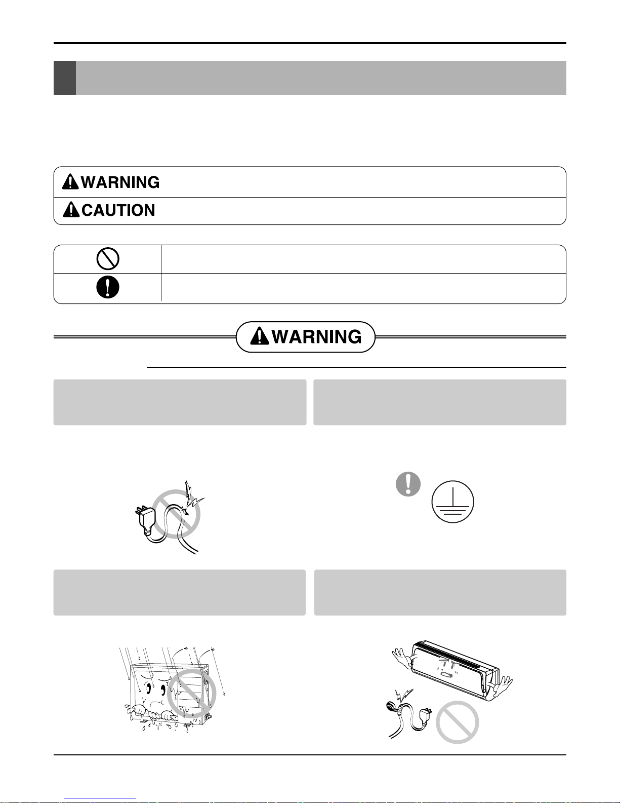
Do not use damaged power cords, plugs, or a
loose socket.
Always use the power plug and socket with the
ground terminal.
• There is risk of fire of electric shock. • There is risk of electric shock.
Install the panel and the cover of control box
securely.
Do not modify or extend the power cord.
• There is risk of fire of electric shock. • No grounding may cause electric shock.
■ Installation
Service Manual 2
Safety Precautions
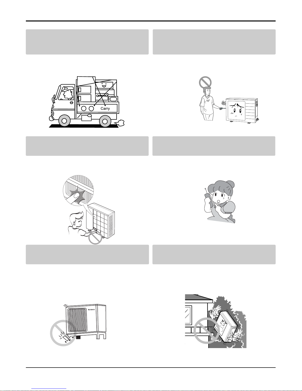
Do not install the product on a defective installation stand.
Be sure the installation area does not
deteriorate with age.
• It may cause injury, accident, or damage to the
product.
• If the base collapses, the air conditioner could fall
with it, causing property damage, product failure,
and personal injury.
• Sharp edges could cause injury. Be especially careful of the case edges and the fins on the condenser
and evaporator.
•
There is risk of fire, electric shock, explosion, or injury.
Be cautious when unpacking and installing the
product.
For installation, always contact the dealer or
an Authorized service center
For re-installation of the installed product,
always contact a dealer or an authorized service center.
Do not install, remove, or re-install the unit by
yourself.
• There is risk of fire, electric shock, explosion, or
injury.
• There is risk of fire, electric shock, explosion, or
injury.
3 Room Air Conditioner
Safety Precautions
■ Operation
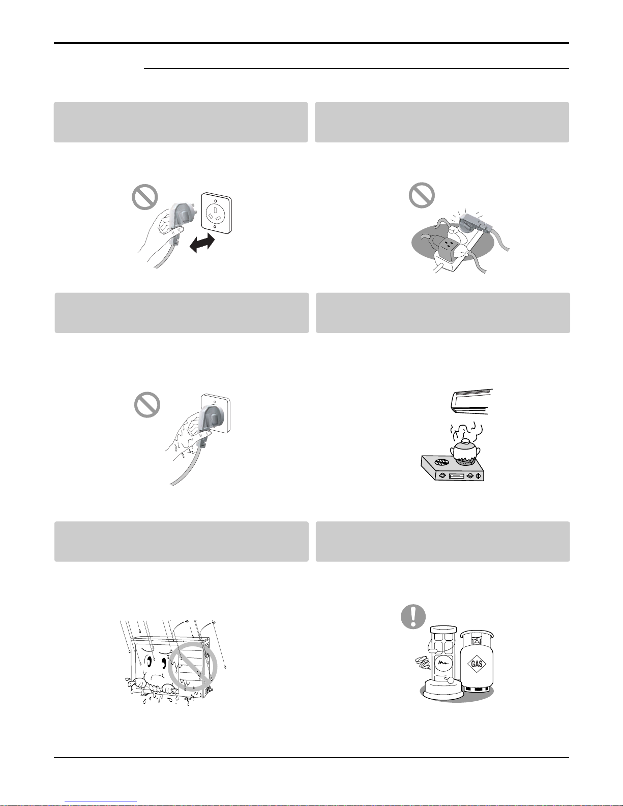
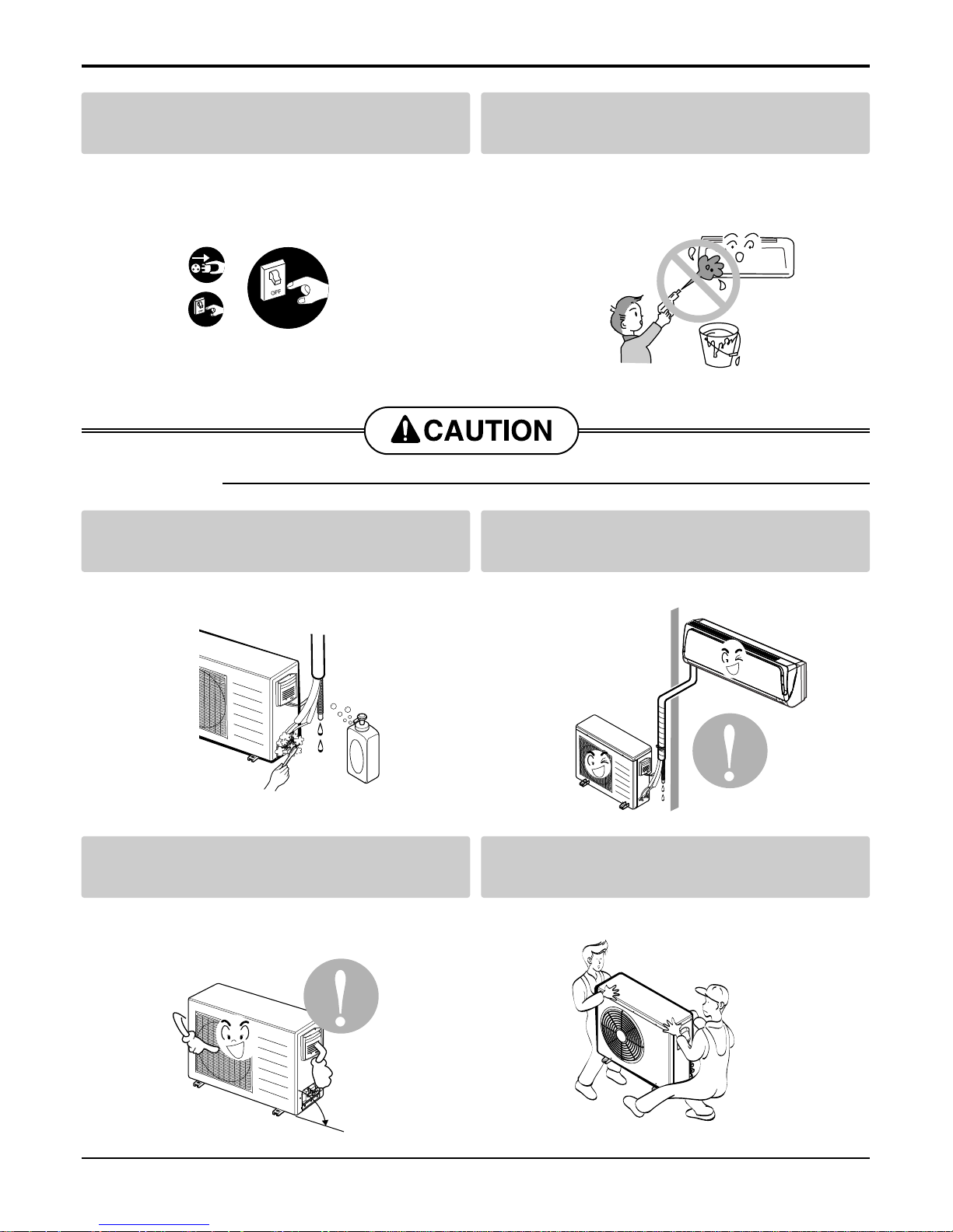
Do not turn the air-conditioner ON or OFF by
plugging or unplugging the power plug.
Use a dedicated outlet for this appliance.
• There is risk of fire or electrical shock. • There is risk of fire or electrical shock.
Grasp the plug to remove the cord from the
outlet. Do not touch it with wet hands.
Do not place a heater or other appliances near
the power cable.
• There is risk of fire or electrical shock. • There is risk of fire and electric shock.
Do not allow water to run into electrical parts. Do not store or use flammable gas or com-
bustibles near the air conditioner.
• There is risk of fire, failure of the product, or electric
shock.
• There is risk of fire or failure of product.
Service Manual 4
Always check for gas (refrigerant) leakage after
installation or repair of product.
Install the drain hose to ensure that water is
drained away properly.
• Low refrigerant levels may cause failure of product. • A bad connection may cause water leakage.
Keep level even when installing the product. Use two or more people to lift and transport
the air conditioner.
• To avoid vibration or water leakage. • Avoid personal injury.
■ Installation
90˚
Unplug the unit if strange sounds, odors, or
smoke comes from it.
Be cautious that water could not enter the
product.
• There is risk of electric shock or fire. • There is risk of fire, electric shock, or product damage.
Safety Precautions
5 Room Air Conditioner
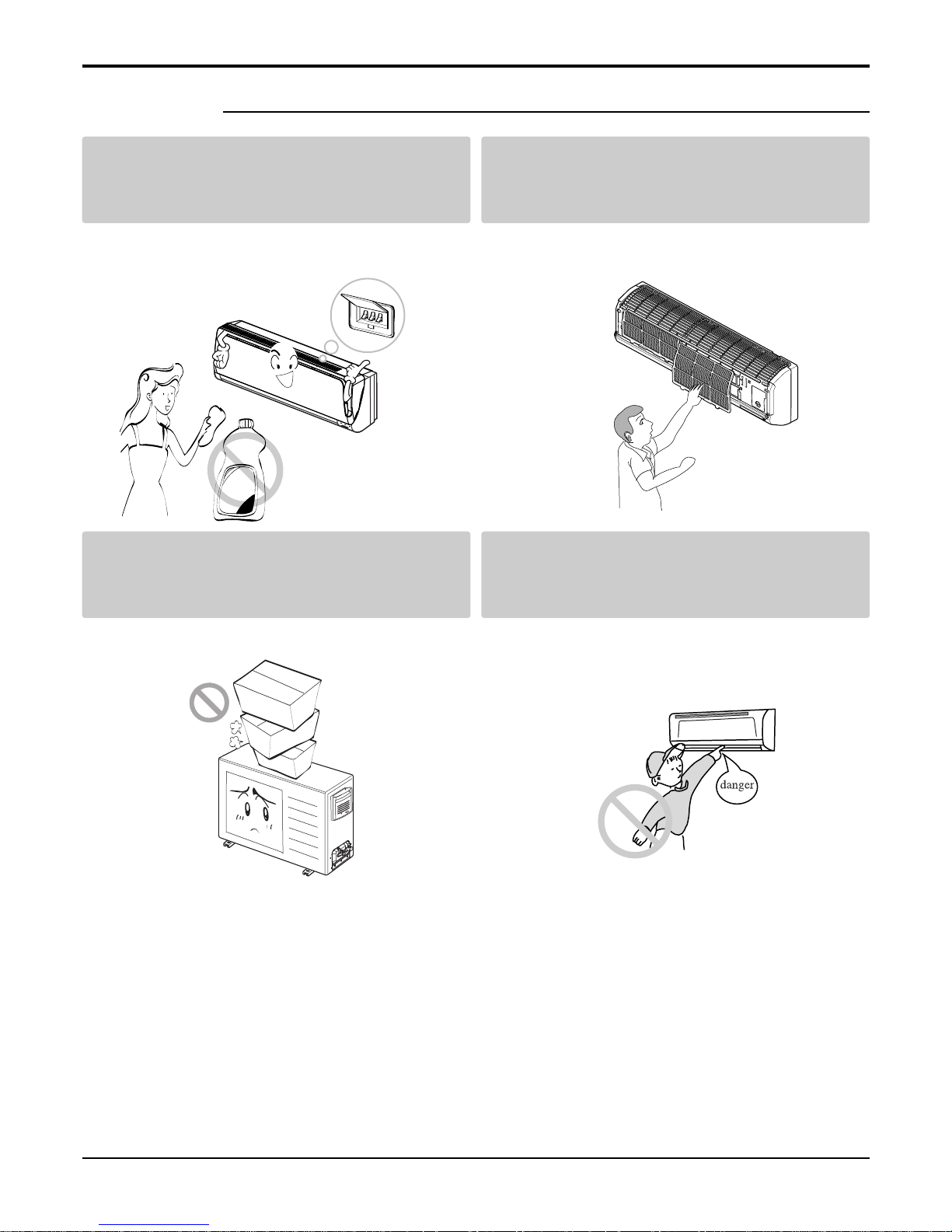
Use a soft cloth to clean. Do not use harsh
detergents, solvents, etc.
Do not touch the metal parts of the product
when removing the air filter. They are very
sharp!
• There is risk of fire, electric shock, or damage to the
plastic parts of the product.
• There is risk of personal injury.
Do not step on or put anyting on the product.
(outdoor units)
Do not insert hands or other objects through
the air inlet or outlet while the air conditioner
is plugged in.
• There is risk of personal injury and failure of product. • There are sharp and moving parts that could cause
personal injury.
■ Operation
x
a
W
Safety Precautions
Service Manual 6
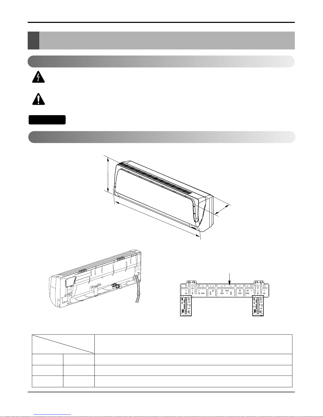
Dimensions
Dimensions
D
H
W
Installation plate
W mm 907
H mm 285
D mm 231
Model
Dimension
18k Btu Series
Indoor Unit
This symbol alerts you to the risk of electric shock.
This symbol alerts you to hazards that could cause harm to the
air conditioner.
This symbol indicates special notes.
NOTICE
Symbols Used in this Manual
7 Room Air Conditioner
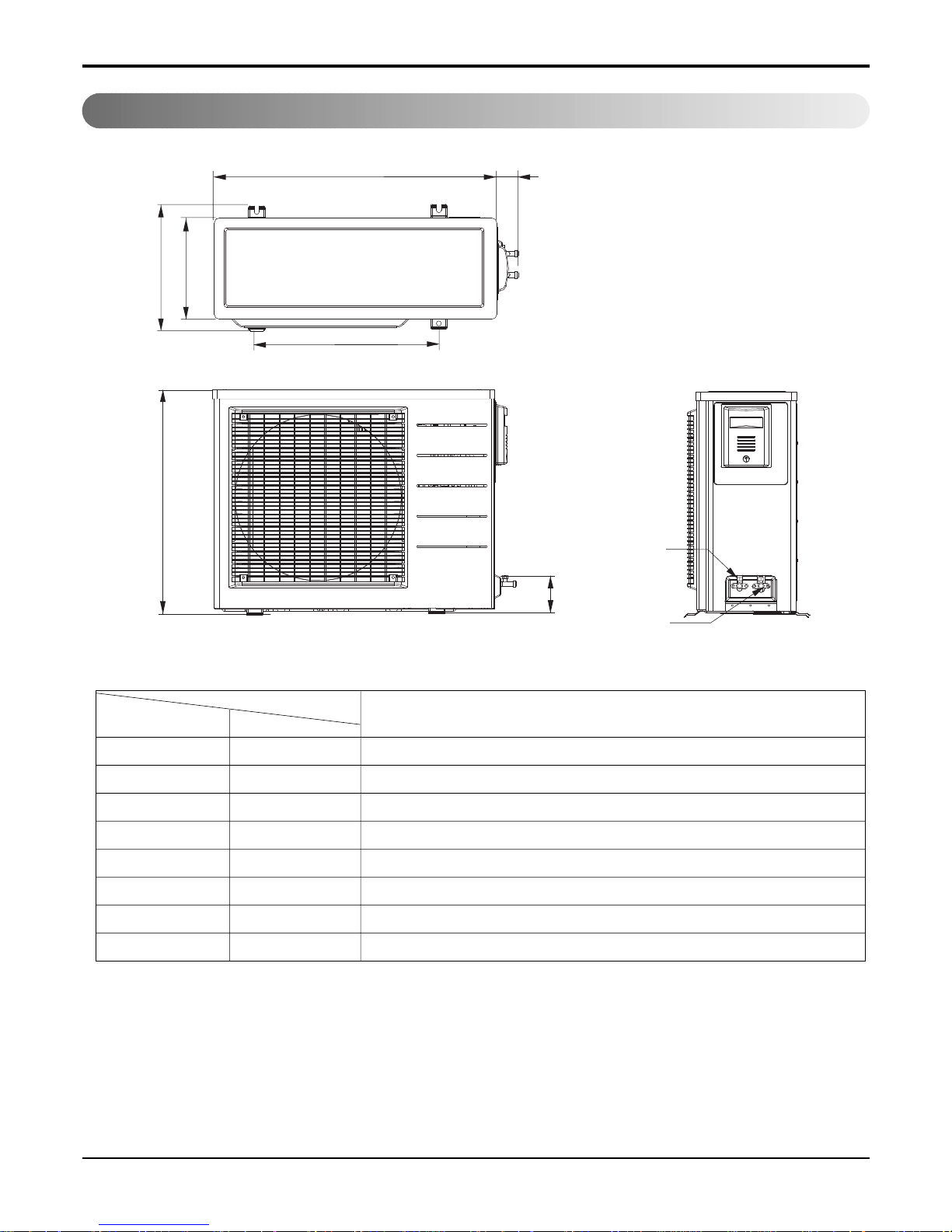
W
L2
L3
1L
D
H
L5
Gas side
(3-way valve)
Liquid side
(2-way valve)
MODEL
DIM unit
W mm 845
H mm 680
D mm 304
L1 mm 378
L2 mm 68
L3 mm 530
L4 mm 14
L5 mm 100
Dimensions
Outdoor Unit
18k Btu Series
Service Manual 8
Product Specifications
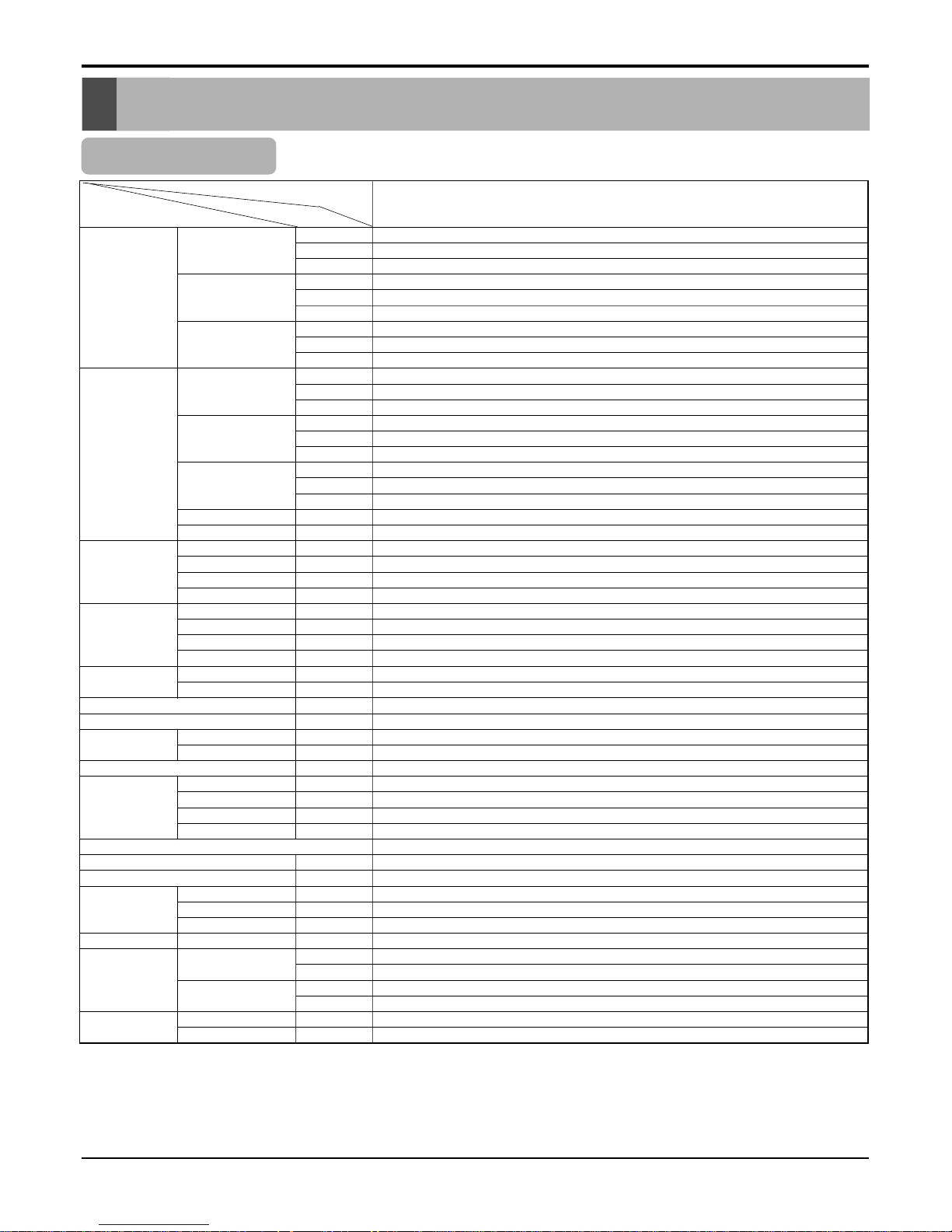
Product Specifications
Table-1
Model Name
Item Unit
W
MIN kcal/h.(W)
Btu/h.
W
Cooling Capacity Type kcal/h.(W)
Btu/h.
W
Max kcal/h.(W)
Btu/h.
W
MIN kcal/h.(W)
Btu/h.
W
Heating Capacity Type kcal/h.(W)
Btu/h.
W
Max kcal/h.(W)
Btu/h.
IN:20°C,Out: -10°C(Heater ON)
Btu/h.
IN:20°C,Out: -10°C(Heater OFF)
Btu/h.
Power Input Cooling W
Heating W
Heating(-10°C,Heater ON)
W
Heating(-10°C,Heater OFF)
W
Running Current Cooling A
Heating A
Heating(-10°C,Heater ON)
A
Heating(-10°C,Heater OFF)
A
COP Cooling W/W
Heating W/W
Power Supply V,Hz
Power Factor %
Air Circulation Indoor,Max m3/min(CFM)
Outdoor,Max m3/min(CFM)
Moisture Removal l/h.(pts/h.)
Noise Level Indoor,High dB(A)±3
(Sound Med. dB(A)±3
Pressure,1m) Low dB(A)±3
Outdoor,Max dB(A)±3
Refrigerant(R410A)Charge
Power Cord DXL
Connecting Cable DXL
Connecting Tube Liquid Side mm(in)
(Ø. Socket Flare) Gas Side mm(in)
Length,std m(in)
Drain Hose (O.D , I.D) mm(in)
Indoor mm
Dimension inch
(W*H*D) Outdoor mm
inch
Net Weight Indoor kg(lbs)
Outdoor
kg(lbs)
1314
1130
4483
4920
4232
16787
5171
4447
17643
1326
1140
4526
5740
4937
19585
6318
5434
21557
-
1728
2140
-
-
7.53
9.36
-
-
2.85
2.68
240/50
98
800
-
2
47
45
42
57
1600
1.5mm2
1.5mm2
6.35(1/4
)
12(1/2)
5(127)
21.5,16.0(0.85,0.63
)
907X290X231
35.7X11.4X9.1
840X675X304
33.1X26.6X12.0
13(29)
52(115)
GWHD18A1NK3EA
9Room Air Conditioner
Installation
Installation
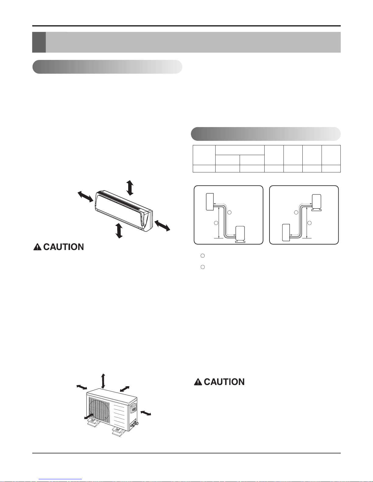
Indoor unit
• Do not have any heat or steam near the unit.
• Select a place where there are no obstacles in front of the
unit.
• Make sure that condensation drainage can be conveniently
routed away.
Do not install near a doorway.
• Ensure that the space around the left and right of the unit is
more than "A". The unit should be installed as high on the
wall as possible, allowing a minimum of "B" from ceiling.
• Use a stud finder to locate studs to prevent unnecessary
damage to the wall.
Outdoor unit
• If an awning is built over the unit to prevent direct sunlight
or rain exposure, make sure that heat radiation from the
condenser is not restricted.
• Ensure that the space around the back and sides is more
than 10cm. The front of the unit should have more than
70cm of space.
• Do not place animals and plants in the path of the warm air.
• Take the air conditioner weight into account and select a
place where noise and vibration are minimum.
• Select a place so that the warm air and noise from the air
conditioner do not disturb neighbors.
Rooftop Installations:
• If the outdoor unit is installed on a roof structure, be
sure to level the unit. Ensure the roof structure and
anchoring method are adequate for the unit location.
• Consult local codes regarding rooftop mounting.
More than 10cm
More than
5cm
More than 2.3m
More than
5cm
• Capacity is based on standard length and maximum allowance length is on the basis of reliability.
Pipe Size
Capacity
(Btu/h)
GA
S LIQUID
Max.
Length
A
(m)
Additional
Refrigerant
(g/m)
Max.
Elevation
B
(m)
Standard
Length
(m)
18k
1/2
"(Ø12.7) 1/4"(Ø6.35) 5 5 15 20
Maximam length of the pipe 15m
Hight less than 5m
Outdoor unit
Indoor unit
A
B
Outdoor unit
Indoor unit
A
B
B
A
Piping Length and Elevation
Install the indoor unit on the wall where the height
from the floors more than 2.3 meters.
More than 10cm More than 10cm
More
than 60cm
More than 60cm
More than 70cm
Selection of the Best Location
Service Manual 10
Installation
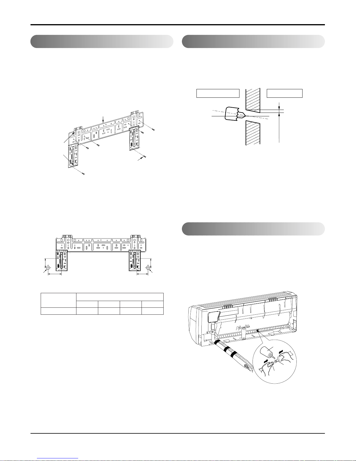
The wall you select should be strong and solid
enough to prevent vibration
1. Mount the installation plate on the wall with four
type A screws. If mounting the unit on a concrete
wall, use anchor bolts.
• Mount the installation plate horizontally by aligning
the centerline using a level.
2. Measure the wall and mark the centerline. It is
also important to use caution concerning the
location of the installation plate-routing of the
wiring to power outlets is through the walls typically. Drilling the hole through the wall for piping connections must be done safely.
• Drill the piping hole with a ø65mm hole core drill.
Drill the piping hole at either the right or the left
with the hole slightly slanted to the outdoor side.
.
•
.
•
.
•
.
• .
How to Fix Installation Plate Drill a Hole in the Wall
Drain hose junction
• Remove the rubber stopple in the desired drain direction.
• Insert drain hose into the handle of drain pan, and join
drain hose and connecting hose according to the figure
by.
Installation Plate
Type "A" screw
Chassis
Hook
5-7mm
(3/16"~5/16")
Indoor
WALL
Outdoor
Installation plate
Left rear piping Right rear piping
Ø70mm
Ø70mm
D B
A
C
Connecting
pa
rt
Adhesi
ve
Drain
hose
A B C D
18
k 105 65 260 65
CHASSIS
(Grade)
Distance (mm)
11 Room Air Conditioner
Flaring work and connection of piping
Flaring work and connection of piping
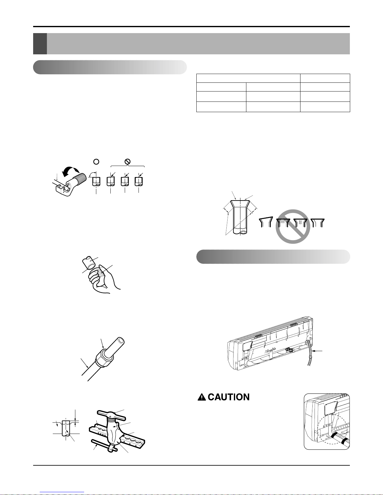
Flaring work
Flaring work
Main cause for refrigerant leakage is due to defect in the
flaring work. Carry out correct flaring work using the following procedure.
Cut the pipes and the cable.
• Use the piping kit accessory or pipes purchased locally.
• Measure the distance between the indoor and the outdoor unit.
• Cut the pipes a little longer than the measured distance.
• Cut the cable 1.5m longer than the pipe length.
Check
• Compare the flared work with figure below.
• If flare is noted to be defective, cut off the flared sec-
tion and re-flare it.
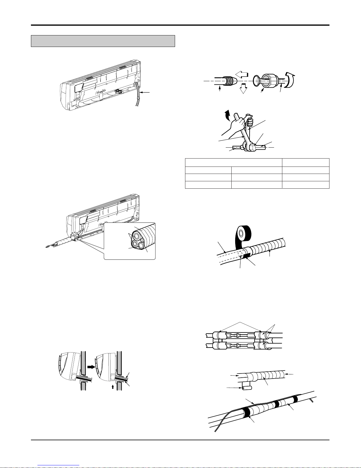
• Preparing the indoor unit's piping and drain hose for installation through the wall.
• Remove the plastic tubing retainer(see illustration below)
and pull the tubing and drain hose away from chassis.
• Replace the plastic tubing holder in the original
position.(Optional)
• Carry out flaring work using flaring tool as shown below.
Burr removal
• Completely remove all burrs from the cut cross section of
pipe/tube.
• Put the end of the copper tube/pipe in a downward direction as you remove burrs in order to avoid dropping burrs
into the tubing.
Putting nut on
• Remove flare nuts attached to indoor and outdoor unit,
then put them on pipe/tube having completed burr removal.
(not possible to put them on after flaring work)
Flaring work
• Firmly hold copper pipe in a die in the dimension shown in
the table above.
Copper
pipe
90°
Slanted Uneven Rough
Bar
Copper pipe
Clamp handle
Red arrow mark
Cone
Yoke
Handle
Bar
"A"
Inclined
Inside is shiny without scratches
Smooth all round
Even length
all round
Surface
damaged
Cracked Uneven
thickness
= Improper flaring =
Drain hose
Pipe
Reamer
Point down
Flare nut
Copper tube
mm inch mm
Ø6.35 1/4 0~0.5
Ø12.7 1/2 0~0.5
Outside diameter A
Connection of piping -- Indoor
When install, make sure that the
remaining parts must be removed
clearly so as not to damage the piping and drain hose, especially power
cord and connecting cable.
Service Manual 12
Flaring work and connection of piping
Route the indoor tubing and the drain hose in the direction of
rear right.
Drain hose
Connecting
cable
Vinyl tape(narrow)
Connection
pipe
Connecting cable
Vinyl tape
(wide)
Wrap with vinyl tape
Indoor
unit pipe
Pipe
Plastic bands
Insulation material
Vinyl tape(narrow)
Adhesive
Drain pipe
Indoor unit drain hose
Wrench
Indoor unit tubing
Open-end wrench (fixed)
Connection pipe
Flare nut
Indoor unit tubing Flare nut Pipes
pipe
Connecting
Connecting cable
Tape
Drain hose
Insert the connecting cable into the indoor unit from the outdoor unit through the piping hole.
• Do not connect the cable to the indoor unit.
• Make a small loop with the cable for easy connection later.
Tape the tubing, drain hose, and the connecting cable. Be
sure that the drain hose is located at the lowest side of the
bundle. Locating at the upper side can cause drain pan to
overflow inside the unit.
NOTE: If the drain hose is routed inside the room, insulate
the hose with an insulation material* so that dripping from
"sweating"(condensation) will not damage furniture or floors.
*Foamed polyethylene or equivalent is recommended.
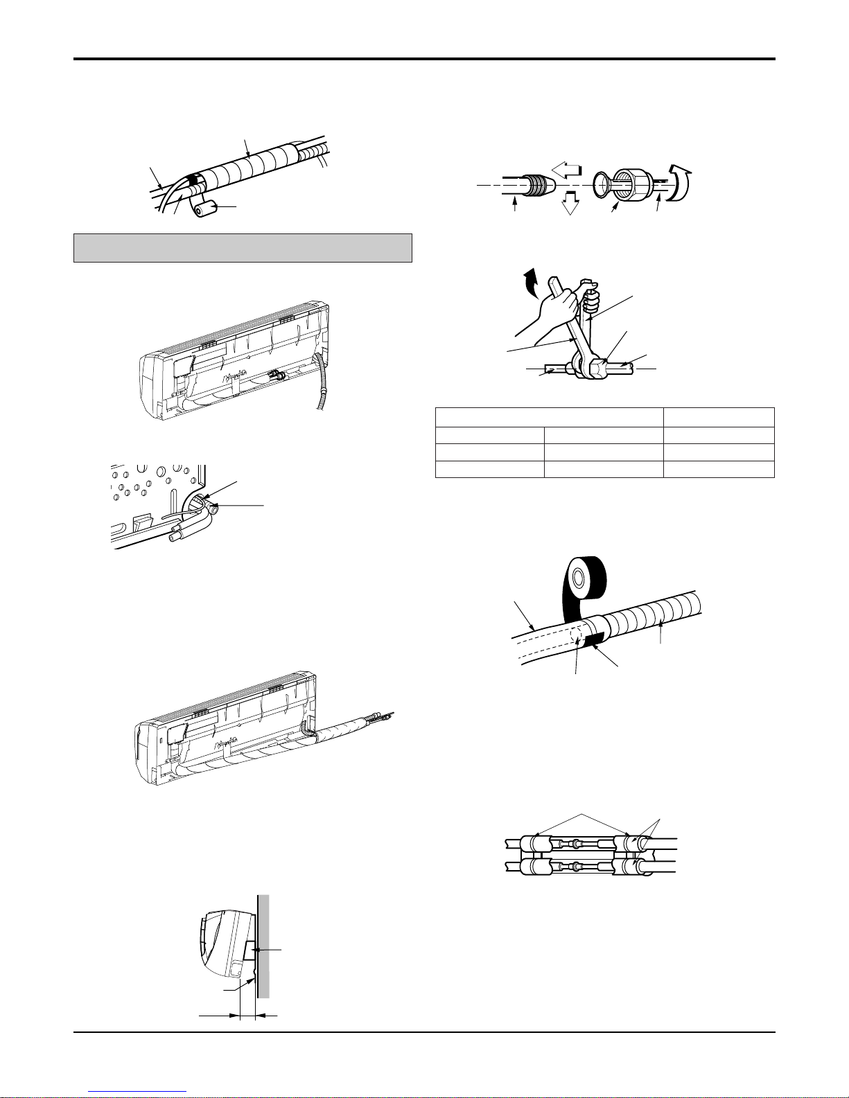
Indoor unit installation
• Hook the indoor unit onto the upper portion of the installation plate.(Engage the two hooks of the rear top of the
indoor unit with the upper edge of the installation plate.)
Ensure that the hooks are properly seated on the installation plate by moving it left and right.
Press the lower left and right sides of the unit against the
installation plate until the hooks engage into their slots(clicking sound).
Connecting the pipings to the indoor unit and
drain hose to drain pipe.
• Align the center of the pipes and sufficiently tighten
the flare nut by hand.
• Tighten the flare nut with a wrench.
• When extending the drain hose at the indoor unit, install the
drain pipe.
Wrap the insulation material around the connecting portion.
•Overlap the connection pipe insulation material and the
indoor unit pipe insulation material. Bind them together with
vinyl tape so that there is no gap.
• Wrap the area which accommodates the rear piping hous-
ing section with vinyl tape.
mm inch kg.m
Ø6.35 1/4 1.8
Ø12.7 1/2 5.5
Outside diameter Torque
For right rear piping
Drain hose
13 Room Air Conditioner
Flaring work and connection of piping
• Bundle the piping and drain hose together by wrapping
them with vinyl tape for enough to cover where they fit into
the rear piping housing section.
Connecting the pipings to the indoor unit and
the drain hose to drain pipe.
• Align the center of the pipes and sufficiently tighten the
flare nut by hand.
• Tighten the flare nut with a wrench.
• When extending the drain hose at the indoor unit, install the
drain pipe.
Wrap the insulation material around the connecting portion.
• Overlap the connection pipe heat insulation and the indoor
unit pipe heat insulation material. Bind them together with
vinyl tape so that there is no gap.
Route the indoor tubing and the drain hose to
the required piping hole position.
Insert the piping, drain hose, and the connecting cable into the piping hole.
Insert the connecting cable into the indoor unit.
• Don't connect the cable to the indoor unit.
• Make a small loop with the cable for easy connection later.
Indoor unit installation
• Hang the indoor unit from the hooks at the top of the installation plate.
• Insert the spacer etc. between the indoor unit and the
installation plate and separate the bottom of the indoor unit
from the wall.
Tape the drain hose and the connecting cable.
• Connecting cable
Drain pipe
Connecting cable
Wrap with vinyl tape
Drain hose
Pipe
Vinyl tape(wide)
Indoor unit tubing Flare nut Pipes
Installation plate
Spacer
Indoor unit
8cm
Plastic bands
Insulation material
Vinyl tape
Adhesive
Drain hose
Indoor unit drain hose
(narrow)
Wrench
Indoor unit tubing
Connection pipe
Flare nut
Open-end wrench (fixed)
For left rear piping
mm inch kg.m
Ø6.35 1/4 1.8
Ø12.7 1/2 5.5
Outside diameter Torque
Service Manual 14
Flaring work and connection of piping
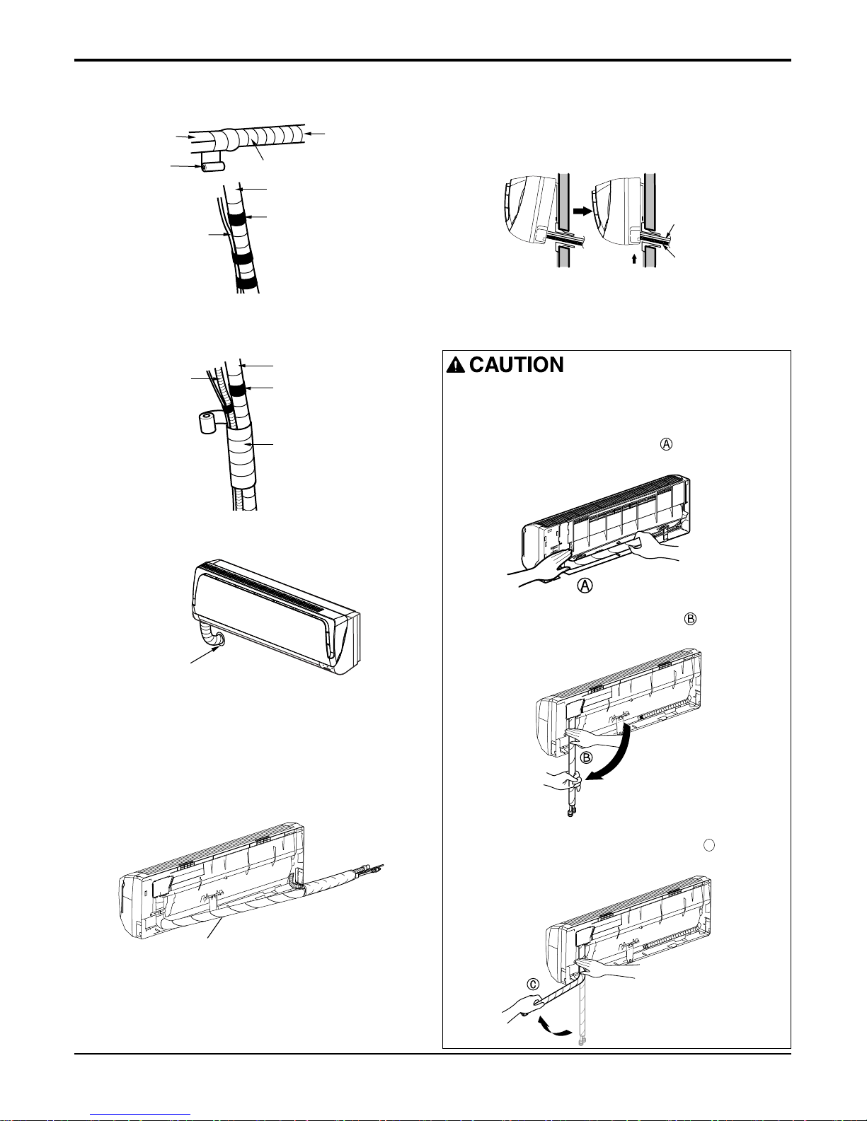
• Wrap the area which accommodates the rear piping housing section with vinyl tape.
Indoor unit installation
• Remove the spacer.
• Ensure that the hooks are properly seated on the installa-
tion plate by moving it left and right.
Press the lower left and right sides of the unit against the
installation plate until the hooks engage into their
slots(clicking sound).
• Bundle the piping and drain hose together by wrapping
them with cloth tape over the range within which they fit
into the rear piping housing section.
Reroute the pipings and the drain hose across
the back of the chassis.
Set the pipings and the drain hose to the back
of the chassis with the tubing holder.
• Hook the edge of tubing holder to tap on chassis and push
the bottom of tubing holder to be engaged at the bottom of
chassis.
Vinyl tape(narrow)
Connection
pipe
Connecting cable
Indoor
unit piping
Pipe
Vinyl tape
(wide)
Wrap with vinyl tape
Drain hose
Vinyl tape(narrow)
Pipe
Wrap with
vinyl tape(wide)
Piping for
passage through
piping hole
Tubing holder
Installation Information (For left piping)
• Good case
For left piping. Follow the instruction below.
• Press on the upper side of clamp. ( )
• Unfold the tubing to downward slowly. ( )
• Bend the tubing to the left side of chassis.( C )
Drain hose
Connecting
cable
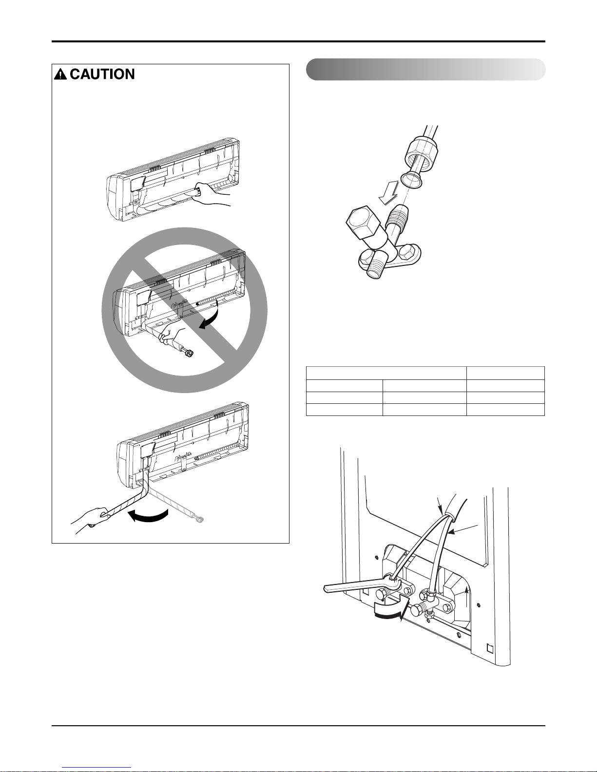
15 Room Air Conditioner
Connection of the pipes-Outdoor
Flaring work and connection of piping
Align the center of the pipings and sufficient
ly
tighten the flare
nut by hand.
Final
ly, tighten the flare nut with torque wrench
until the wren
ch clicks.
• When tightening the flare nut with torque wrench, ensure
the direction for tightening follows the arrow on the wrench.
• Bad case
• Following bending type from right to left could cause
problem of pipe damage.
Outdoor unit
Gas side piping
(Bigger diameter)
Liquid side
piping
(Smaller
diameter)
mm inch kg.m
Ø6.35 1/4 1.8
Ø12.7 1/2 5.5
Outside diameter Torque
Service Manual 16
Connect the cable to the Indoor unit.
Connecting the cable between indoor unit and outdoor unit
Connecting the cable between indoor unit and outdoor unit
Connect the cable to the indoor unit by connecting the wires to the terminals on the control board individually
according to the outdoor unit connection. (Ensure that the color of the wires of the outdoor unit and the terminal No.
are the same as those of the indoor unit.)
• The above circuit diagram is subject to change without notice.
• The earth wire should be longer than the common wires.
• When installing, refer to the circuit diagram behind the panel front of the indoor unit.
• Connect the wires firmly so that they may not be pulled out easily.
• Connect the wires according to color codes, referring to the wiring diagram.
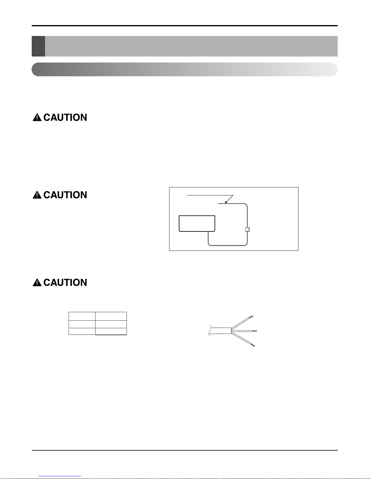
If a power plug is not used, provide a circuit
breaker between power source and the unit as
shown by.
Air
Conditioner
Main power source
The power cord connected to the indoor unit and the power connecting cable connecting the indoor and outdoor
unit should be selected according to the following specifications (Type "B" approved by HAR or SAA).
H07RN-FH05W-F
Connecting cable
(mm2)
Power cord
1.5
1.5
Circuit Breaker
Use a circuit
breaker or time
delay fuse.
17 Room Air Conditioner
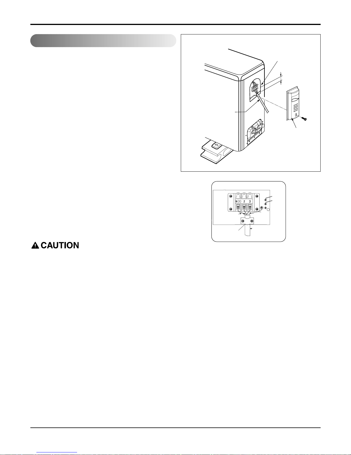
Connecting the cable between indoor unit and outdoor unit
Rem
ove the control cover from the unit by
loosening the scr
ew.
Connect the wires to the terminals on the control board individually.
Secure the ca
ble onto the control board with
the co
rd clamp.
Refix the cont
rol cover to the original position
with the scr
ew.
Use a recogni
zed circuit breaker "A"
between the power source and the unit.
A disconnecting d
evice to adequately discon-
nect all supp
ly lines must be fitted.
This Air-conditioner use 20A.
After the confirmation of the above conditions, prepare the wiring as follows:
1) Never fail to have an individual power circuit specifically for the air conditioner. As for the method of wiring,
be guided by the circuit diagram posted on the inside of control cover.
2) The screw which fasten the wiring in the casing of electrical fittings are liable to come loose from vibrations
to which the unit is subjected during the course of transportation. Check them and make sure that they are
all tightly fastened. (If they are loose, it could cause burn-out of the wires.)
3) Specification of power source.
4) Confirm that electrical capacity is sufficient.
5) See to that the starting voltage is maintained at more than 90 percent of the rated voltage marked on the
name plate.
6) Confirm that the cable thickness is as specified in the power source specification.
(Particularly note the relation between cable length and thickness. (Refer to page 8))
7) Always install an earth leakage switch having operating current not exceeding 30mA in a wet or moist area.
8) The following would be caused by voltage drop.
• Vibration of a magnetic switch, which will damage the contact point, fuse breaking, disturbance of the normal func-
tion of the overload.
9) The means for disconnection from a power supply shall be incorporated in the fixed wiring and have an air
gap contact separation of at least 3.5mm in each active(phase) conductors.
Terminal block
Over 5mm
Cover control
Connecting cable
Outdoor Unit
Power connection cord
Wire clamp
YE/GN
Blue
Black
Brown
Connect the cable to the outdoor unit
 Loading...