

DeLonghi ceramic COOKTOPS Use And Care Instructions Manual

distributed by
Pty Ltd
DèLonghi
LCH
ceramic
COOKTOPS
INSTALLATION and SERVICE INSTRUCTIONS
USE and CARE INSTRUCTIONS
CAUTION:
< In order to avoid a hazard this appliance must be installed according to
these instructions for installation.
WARNING:
< This appliance is to be installed only by an authorised person.
< This appliance must be used only for the task it has explicitly been designed
for, that is for cooking foodstuffs. Any other form of usage is to be considered as
inappropriate and therefore dangerous.
< Do NOT place combustible materials or products on this appliance at any time.
< Do NOT spray aerosols in the vicinity of this appliance while it is in use.
TECHNICAL INFORMATIONS:
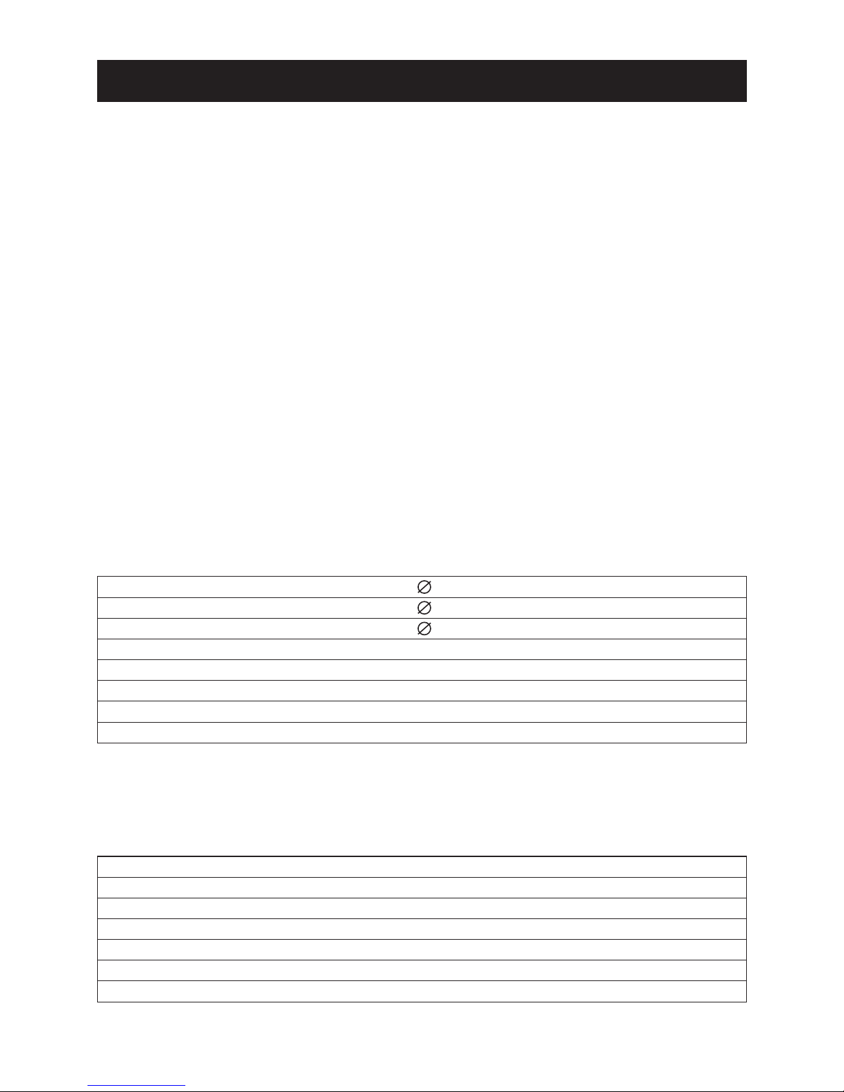
DIMENSIONS (Table 2):
(Note: Also refer to Figure 1 side)
Use and Care
INSTALLATION
2
General Dimensions
Width
Depth
575 mm
Cut-out Dimensions
Depth Below Mounting Surface
Width
Depth
505 mm
52 mm
560 mm
490 mm
Triple circuit hotplate
145 1200-1300 W
nr. 2
Triple circuit hotplate
180 1700-1850 W
nr. 1
Triple circuit hotplate
195 1900-2050 W
nr. 1
Hotplate and residual heat indicator
“ON” indicator light
Glass overheat cut-out device
nr. 1
Voltage
230-240 V~ / 400-415 V 3N~ 50 Hz
Maximum absorbed power
6000 - 6500 W
nr. 1
nr. 4
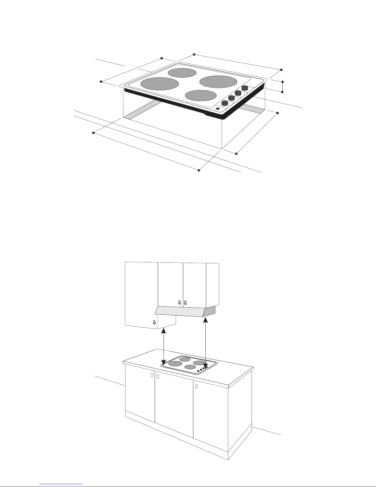
Figure 1
CLEARANCES:
Installation clearances and protection of combustible surfaces shall comply with
page 4.
Figure 2
3
57
5
505
5
2
560
490
450 mm
750 mm

The installation shall comply with the dimensions in Figures 1 and 2, bearing in
mind that:
< A minimum clearance of 40 mm has to be kept between the bottom of the
cooking hob and the top af an appliance or a thermal barrier (see next
page).
< Overhead clearances - In no case shall the clearances between the
highest part of the hob and a range hood be less than 600 mm, or for an
overhead axhaust fan, 750 mm. Any other downward facing combustible
surface less than 600 mm above the highest part of the hob shall be
protected for the full width and depth of the cooking surface area.
However, in no case shall this clearance to any surface be less than
450 mm.
< Side clearances - Where the dimension from the periphery of the nearest
hotplate to any vertical combustible surface is less than 200 mm, the
surface shall be protected to a height of not less than 150 mm above the
hob for the full dimension (width or depth) of the cooking surface area.
< Protection of combustible surfaces - The required protection shall
ensure that the surface temperature of the combustible surface does not
exceed 50°C above ambient. The fixing of 5 mm tick ceramic tiles to the
surface or attaching fire resistant material to the surface and covering with
sheet metal with minimum tickness of 0,4 mm would satisfy this
requirement.
CAUTION :
The underside surface of the cooking hob can reach a temperture exceeding
105°C during normal use.
If after installation the underside surface is accessible throught under-bench
cupboard doors and the like, it is essential that a rigid barrier is installed so
that such access is restricted. In order to avoid a hazard the barrier must be
of low thermal conductivity material installed according to the instructions
for installation.
Use and CareUse and Care
4
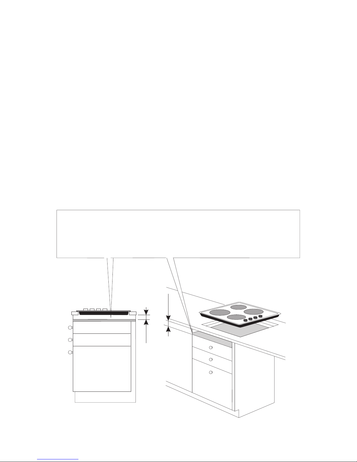
THERMAL BARRIER INSTALLATION :
WARNING:
< If the hob is installed over drawers or cupboards, a thermal
protection barrier must be fitted at least 40 mm beneath the base of
the hob (see Figure 3).
Note:
< Above not applicable if hob is mounted directly above an oven.
< For access to the hob for servicing or installation, ensure that the barrier
can be removed from beneath by the use of a tool.
< A gap of 20 mm may be allowed at rear for electrical connection and
ventilation
Figure 3
5
THERMAL PROTECTION BARRIER (min 15 mm thick)
Fitted the full lenghts of the hob below the workbench and must be
removable with the use of a tool for installation and service.
40 mm40 mm
40 mm40 mm
 Loading...