

DeLonghi AP 1246 G Installation And Service Instructions Manual

INSTALLATION and SERVICE INSTRUCTIONS
USE and CARE INSTRUCTIONS
AP 1246 G
DUAL FUEL
COOKER
distributed by
DèLonghi
Pty Ltd

2
PRODUCT LABEL
Dear Customer,
Thank you for having purchased and given your preference to our product.
The safety precautions and recommendations reported below are for your
own safety and that of others. They will also provide a means by which to
make full use of the features offered by your appliance.
Please keep this booklet in a safe place. It may be useful in future, either to
yourself or to others in the event that doubts should arise relating to its
operation.
This appliance must be used only for the task it has explicitly been
designed for, that is for cooking foodstuffs. Any other form of usage is to be
considered as inappropriate and therefore dangerous.
The manufacturer declines all responsibility in the event of damage caused
by improper, incorrect or illogical use of the appliance or be faulty
installation.
This cooker has been designed and constructed in accordance with the following codes
and specifications:
AGA101 (AS 4551) Approval Requirements for Domestic Gas cooking appliances
AS/NZS 3350-1 General Requirements for Domestic electrical appliances
AS/NSZ 3350-2-6 Particular Requirements for Domestic electrical cooking appliances
AS/NSZ 1044 Electromagnetic Compatibility Requirements.
IMPORTANT:
■ This appliance is designed and manufactured solely for the cooking of domestic
(household) food and is not suitable for any non domestic application and therefore
should not be used in a commercial environment.
■ The appliance guarantee will be void if the appliance is used within a non domestic
environment i.e. a semi commercial, commercial or communal environment.
■ WARNING: Accessible parts will become hot when in use.
To avoid burns and scalds children should be kept away.
3
FIRST TIME USE THE OVEN
It is advised to follow these instructions:
■ Insert shelves and tray.
■ Switch on the empty oven on max to eliminate grease tracks from the heating elements.
■ Let the oven cool down, switch off the electrical supply, then clean the inside of the oven with a cloth soaked in water and
neutral detergent and dry thoroughly.
■ Clean the interior of the oven with cloth soaked in water and detergent (neutral) then dry carefully.
IMPORTANT PRECAUTIONS AND RECOMMENDATIONS FOR
USE OF ELECTRICAL APPLIANCES
Use of any electrical appliance implies the necessity to follow a series of fundamental rules.
In particular:
■ Never touch the appliance with wet hands or feet;
■ Do not operate the appliance barefooted;
■ The appliance is not intended for use by young children or infirm persons with
supervision
■ Young children should be supervised to ensure they do not play with the
appliance
The manufacturer cannot be held responsible for any damages caused by improper, incorrect or illogical use of the appliance.
IMPORTANT PRECAUTIONS AND RECOMMENDATIONS
After having unpacked the appliance, check to ensure that it is not damaged.
In case of doubt, do not use it and consult your supplier or a professionally qualified technician.
Packing elements (i.e. plastic bags, polystyrene foam, nails, packing straps, etc.) should not be
left around within easy reach of children, as these may cause serious injuries.
■ Do not attempt to modify the technical characteristics of the appliance as this may
become dangerous to use.
■ Do not carry out cleaning or maintenance operations on the appliance without
having previously disconnected it from the electric power supply.
■ After use, ensure that the knobs are in off position.
■ Do not allow children or other incapable people to use the appliance without
supervision.
■ During and after use of the cooker, certain parts will become very hot. Do not
touch hot parts.
■ Keep children away from the cooker when it is in use.
■ Young children should be supervised to ensure that they do not play with the
appliance.
■ Some appliances are supplied with a protective film on steel and aluminium parts.
This film must be removed before using the appliance.
■ Fire risk! Do not store flammable material in the ovens and in the warming drawers.
■ Make sure that electrical cables connecting other appliances in the proximity of the
cooker cannot come into contact with the hob or become entrapped in the oven
doors.
■ Do not line the oven walls with aluminium foil. Do not place baking trays or the drip
tray on the base of the oven chamber.
■ The manufacturer declines all liability for injury to persons or damage to property
caused by incorrect or improper use of the appliance.
■ IMPORTANT NOTE: WHERE THIS APPLIANCE IS INSTALLED IN MARINE
CRAFT OR IN CARAVANS, IT SHALL NOT BE USED AS A SPACE HEATER.
■ WARNING: In order to prevent accidental tipping of the appliance, for example
by a child climbing onto the open oven door the stabilizing means must be
installed. Please refer to instructions for installation.
IMPORTANT

4
CAUTION:
■ This appliance must be installed in accordance with these installation instruc-
tions.
■ This appliance shall only be serviced by authorized personnel.
■ This appliance is to be installed only by an authorised person.
■ Incorrect installation, for which the manufacturer accepts no responsibility,
may cause personal injury of damage.
■ Always disconnect the cooker from mains power supply before carrying out
any maintenance operations or repairs.
■ In the room where the cooker is installed, there must be enough air to allow the
gas to burn correctly, according to the current local regulations.
ELECTRICAL REQUIREMENTS
■ The appliance must be connected to the mains checking that the voltage
corresponds to the value given in the rating plate and that the electrical cable
sections can withstand the load specified on the plate.
■ The appliance must be connected directly to the mains placing a two pole
switch with minimum opening between the contacts of 3 mm between the
appliance and the mains.
■ The power supply cable must not touch the hot parts and must be positioned
so that it does not exceed 50°C above ambient.
■ Once the appliance has been installed, the switch must always be accessible.
■
If the supply cord is damaged it must be replaced by the manufacturer or
it’s Service Agent or a similarly qualified person in order to avoid a hazard.
WARNING: This cooker must be connected to electrical supply using V105
insulated cable.
N.B. The connection of the appliance to earth is mandatory.
If the installation requires alterations to the domestic electrical system call a qualified
electrician.
He should also check that the domestic electrical system is suitable for the power
drawn by the appliance.
Figure 1.1
Figure 1.2a
PE
12345
N (L2)L1
230 V - 240 V
230 V3 - 240 V3
PE
12345
PE
12345
PE
12345
400 V 2N - 415 V 2N
400 V 3N - 415 V 3N
L1
L
2 L3
N
L1 L2 L3
N
L1 L2
INSTALLATION
1
C
D
A
B
5
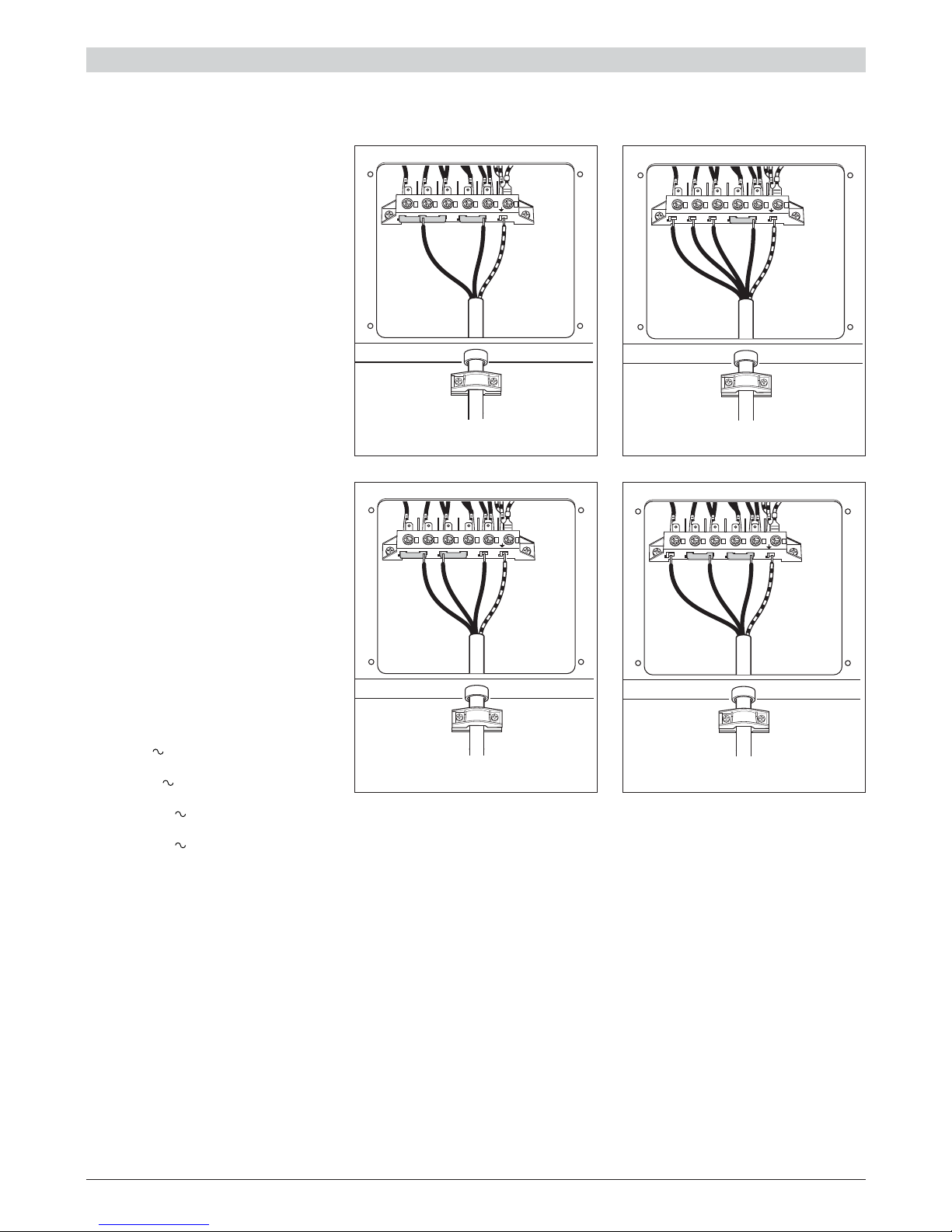
CONNECTING THE FEEDER
CABLE
To connect the feeder cable to the cooker
it is necessary to:
■ Remove the 4 screws that hold
shield A behind the cooker.
■ Open completely the cable clamp D.
■ Position the U bolts onto terminal
block B (fig. 1.1) according to the
diagrams in figs. 1.2a - 1.2b.
■ Insert the feeder cable into the cable
save C. The supply cable must be
of a suitable size for the current
requirements of the appliance; see
the section “Feeder cable section”.
■ Connect the phase and earth cables
to terminal B according to figures
1.2a - 1.2b.
■ Pull the feeder cable and block it
with the cable clamp D
■ Re-mount shield A.
N.B. The earth conductor must be left
about 3 cm longer than the others.
Figure 1.2b
FEEDER CABLE SECTION
type “H05RR-F”
230-240 V 3 x 4 mm2(**)
230 -240 V3 4 x 2,5 mm
2
(**)
400 -415 V 3N 5 x 2,5 mm
2
(**)
400 -415 V 2N 4 x 2,5 mm
2
(**)
(**) – Connection with wall box connection
– Diversity factor applied
INSTALLATION
230-240 V ~
23451
N(L2)
PE
L1
230 V 3 - 240 V 3 ~
23451
PE
L1 L2 L3
400 V 3N - 415 V 3N ~
23451
PE
L1 L2 L3 N
400 V 2N - 415 V 2N ~
23451
PE
L1 L2 N
6
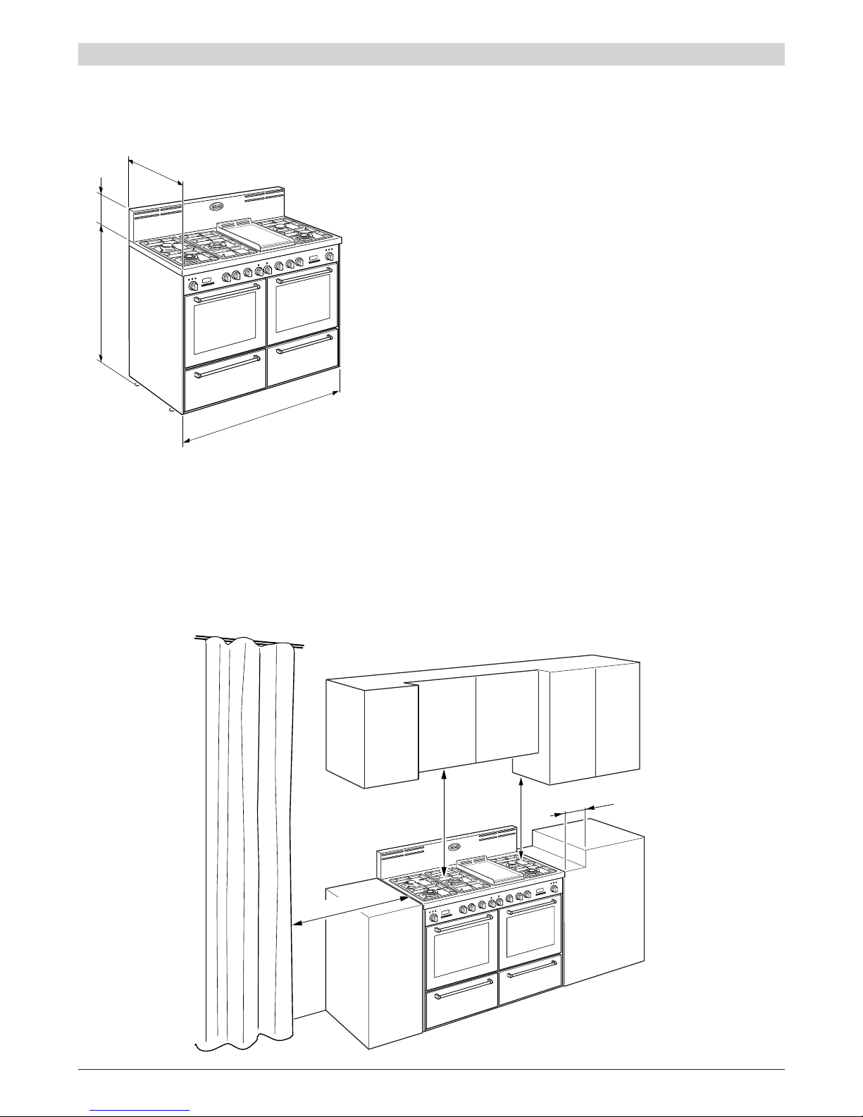
(450 mm)
(650 mm)
(500 mm)
(200 mm)
Fig. 1.4
INSTALLATION
Figure 1.3
Figure 1.4
CLEARANCES
■ Installation clearances and protection of combustible surfaces shall
comply with the current local regulations eg. AG 601 (AS 5601) Gas
Installations code.
■ Installation shall comply with the dimension in Fig 1.4 bearing in mind
that
Overhead Clearances
■ In no case shall the clearances between the highest part of the cooker
be less than 600mm or for an overhead exhaust fan 750mm. All other
downward facing combustible surfaces less than 600mm above the
cooker surface shall be protected for the full width of the cooking surface
in accordance with the standards noted above. In no case shall the
clearance be less than 450mm.
Rear and Side Clearances
■ Where the dimensions from the periphery of the nearest burner to any
vertical combustible surface is less than 200mm the surface shall be
protected in accordance with the standards to a height of not less than
150mm above the cooking surface for the full width or depth of the
cooking surface
■ Where the dimensions from the periphery of the nearest burner to any
horizontal combustible surface is less than 200mm, the horizontal surface
shall be greater than 10mm below the surface of the hob, or the
horizontal surface requirement above.
Protection of combustible surfaces.
■ The standards above specify that where required protection shall ensure
that the surface temperature of the combustible surface does not exceed
65°C above room temperature.
If the cooker is located on a pedestal it is necessary to provide safety measures
to prevent falling out.
203 mm
608 mm
1216 m
m
min 915 mm
max 927 mm
7
A
A
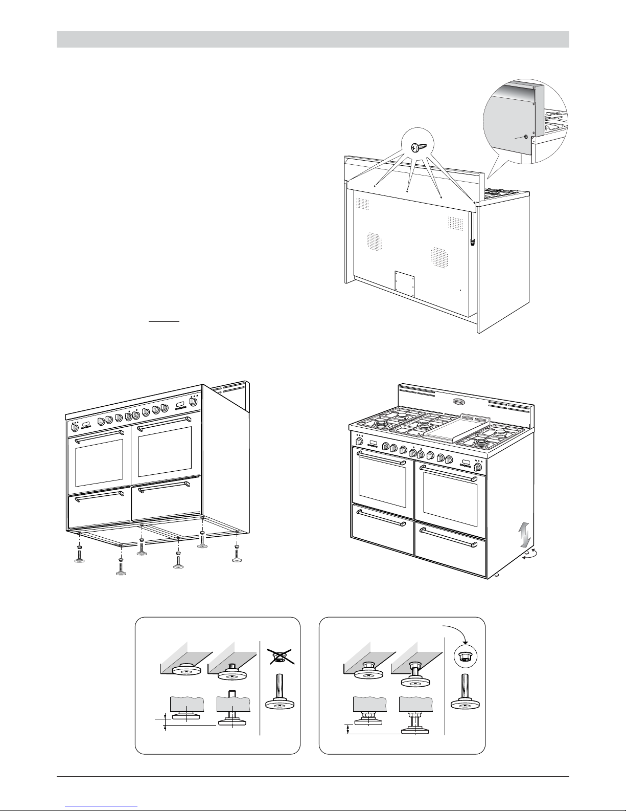
ASSEMBLING THE BACKGUARD
It is mandatory to install the backguard
■ Assemble the backguard as shown in figure 1.5 and
fix it by screwing the 5 screws “A”.
LEVELLING THE COOKER
■ The range is equipped with 6 LEVELLING FEET (already
fitted on the appliance) and may be levelled by screwing or
unscrewing the feet (fig. 1.7).
■ It is important to observe the prescriptions of figures 1.6,
1.8a, 1.8b.
+ 8 mm
+ 8 mm
0 mm
+ 12 mm
Supplied with the range
in a separate kit
INSTALLATION
Figure 1.5
Figure 1.6 Figure 1.7
Figure 1.8a Figure 1.8b
8
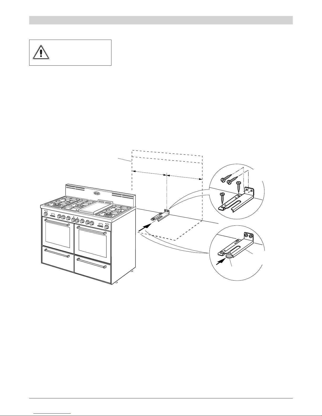
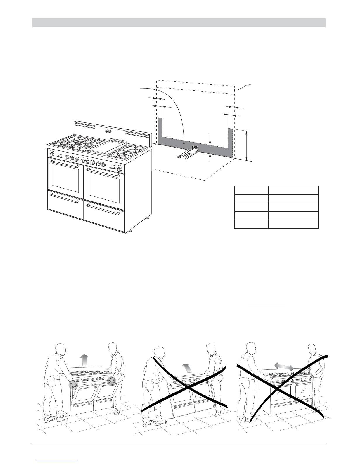
ANTI-TIP STABILITY DEVICE INSTALLATION INSTRUCTIONS
WARNING: In order to prevent accidental tipping of the appliance, for example by a child climbing onto the open oven door, the stabilizing means must
be installed. Please refer to instructions for installation.
1. The anti-tip bracket has to be attached as shown on figure below (only rear cental
position), it has to be fixed on the floor and on the rear wall by no. 4 (four) suitable
screws (not supplied).
2. After fixing the anti-tip bracket, slide range into place. Be sure the rear central foot
slides under the anti-tip bracket attached.
=
=
Dotted line showing the position
of the range when installed
ANTI-TIP
STABILITY
DEVICE FIXING
Rear central
feet of range
Anti-tip
stability device
YOU MUST USE STABILITY
ANTI TIP BRACKET TO
PREVENT UNIT FROM
TIPPING.
INSTALLATION
Figure 1.9
9
Figure 1.11
Figure 1.12
Figure 1.13
WARNING
To move the cooker always ensure
two people carry out this manoeuvre
to prevent damage to the appliance
(fig. 1.11).
MOVING THE COOKER
WARNING
Be carefull: do not lift the cooker by
the door handles (fig. 1.12).
WARNING
When moving cooker to its final position DO
NOT DRAG (fig. 1.13).
Lift feet clear of floor (fig. 1.11).
INSTALLATION
A
D
B
B
C
C
GAS AND ELECTRIC CONNECTION
Dotted line showing the
position of the range
when installed
* : Depending on feet regulation
Area for GAS and ELECTRIC connection
Rif. mm
A 400
B 71
C 16,5
D
107 - 119
(*)
Figure 1.10
10
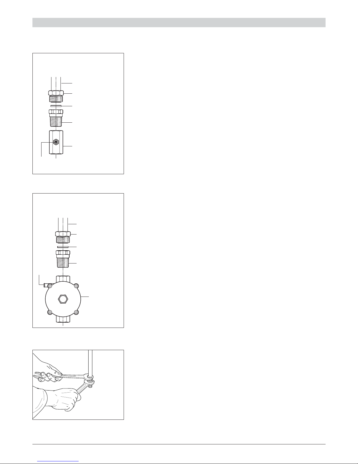
GAS SUPPLY:
■ The connection must be performed by an authorised person according to the rel-
evant standards.
■ Before connecting the appliance to the gas main, mount the brass conical adap-
tor onto the gas inlet pipe, upon which the gasket has been placed (figures 1.14a-
1.14b).
Conical adaptor and gasket are supplied with the appliance (packed with conversion kit for use with Natural gas or Universal LPG).
■ This appliance is suitable for use with Natural Gas or Universal LPG. (Check the
“gas type” sticker attached to the appliance).
■ For Natural Gas models the gas supply is connected to the pressure regulator
which is supplied with the appliance (fig. 1.14b). Adjust the regulator to obtain a
test point pressure of 1 kPa with both of the triple ring burners operating at the
maximum.
■ For Universal LPG models the gas supply is connected to the test point adaptor
which is supplied with the appliance (fig. 1.14a) and ensure that the supply pressure is regulated to 2.75 kPa.
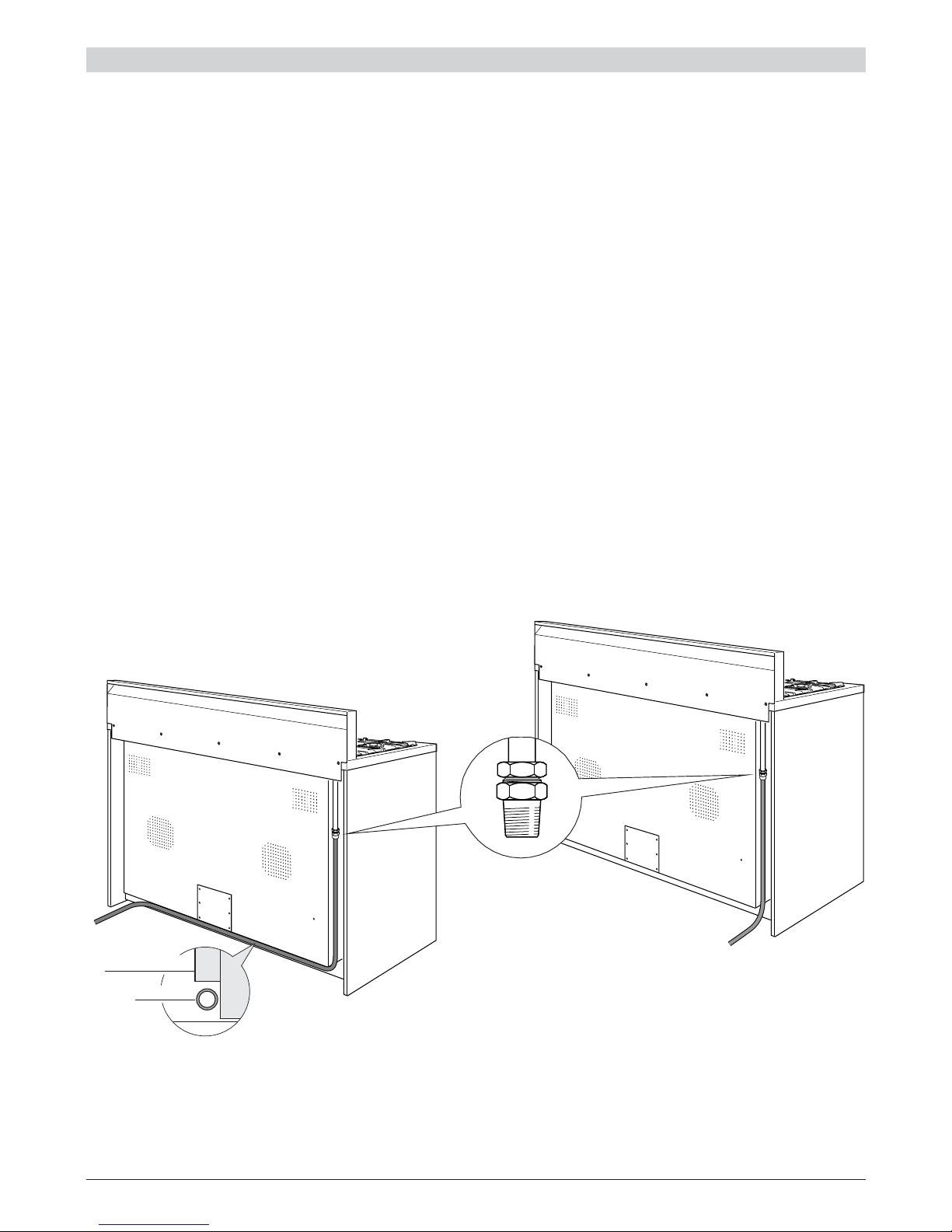
■ The connection must be made at the rear of appliance. If the connection pipe
cross the cooker, it must be positioned under the cooker rear protection (fig.
1.16).
■
IMPORTANT: Use two spanners to tighten or loosen the connecting pipe (fig.
1.15)
Figure 1.14b
Gas connection for
NATURAL GAS
Gas inlet pipe
Nipple
Gasket
Brass conical adaptor
(Thread tight: use
suitable seal)
Gas regulator
Test
point
Gas connection for
UNIVERSAL LPG
Figure 1.14a
Gas inlet pipe
Nipple
Gasket
Brass conical adaptor
(Thread tight: use
suitable seal)
Test point adaptor
Test
point
Figure 1.15
INSTALLATION
11
1. After connecting the gas supply, check the piping and connections for leaks using
a soap and water solution. The presence of bubbles indicates a leak, tighten or
replace connections as appropriate.
Warning: Do not use any naked flame to check for leaks.
2. Adjust the test point pressure or supply pressure to the value which is appropriate
for the gas type.
3. The operation of the appliance must be tested when installation is completed.
4. Turn on the appliance gas controls and light each burner individually and in combination. Check for a well defined blue flame without any yellow tipping. If any abnormality is evident then check that the burner cap is located properly and the injector
nipple is aligned correctly.
5. Check the minimum burner setting by quickly rotating the gas control knob from the
maximum to the minimum position, the flame must not go out. If adjustment is
required carry out the “Setting the burner minimum" procedure described.
6. If satisfactory performance cannot be obtained, the installer shall check the installation and notify the local gas supply authority for a gas supply problem, or if it is
an appliance problem, our Customer Service Centre should be called to obtain the
nearest authorized Delonghi Service Agent.
Figure 1.16
gas pipe
cooker
rear protection
WARNING, This appliance IS NOT SUITABLE for installation with a hose
assembly.
INSTALLATION
12
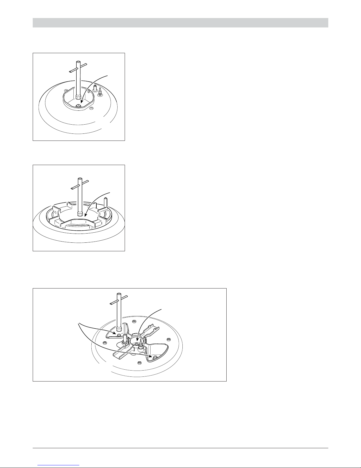
CONVERSION PROCEDURE (to convert to Universal LPG)
REPLACING THE INJECTORS
The conversion procedure must be carried out only by an authorised person.
This appliance is suitable for use with Natural gas or Universal LPG (check the “gas
type” sticker attached to the appliance). A label stating the type of gas used after
replacing the injectors must be attached at the rear of the appliance, in proximity of the
gas inlet connection. The nominal gas consumption and injector size details are provided in table at page 15.
To r eplace the injectors proceed as follows:
■ Remove pan supports and burners from the cooktop.
■ Using a spanner, remove the injectors J (figs. 1.17a, 1.17b, 1.17c) and replace
them with the correct ones according to the gas type (see following tables page 15).
■ Affix to the rear of the appliance, in proximity of the gas inlet connections, the
warning label (supplied with the conversion kit) stating that the cooker has been
converted for use with Universal LPG / Natural gas.
IMPORTANT
■ If the cooker is suitable for use with Natural gas and must be converted for use
with Universal LPG, before connecting to gas main remove the appliance gas
regulator and replace with test point adaptor (see figs. 1.14a-1.14b).
■ If the cooker is suitable for use with Universal LPG and must be converted for
use with Natural gas, before connecting to the gas main remove the appliance
test point adaptor and replace with gas regulator (see figs. 1.14a-1.14b).
NOTE:
Gas regulator and test point adaptor are supplied with the appliance (packed with conversion kit).
The burners are designed so that regulation of primary air is not required.
Rapid
burner
Triple ring
burner
DUAL
burner
J
Injector for inner crown
J
Injectors for
outer crowns
J
J
INSTALLATION
Figure 1.17c
Figure 1.17b
Figure 1.17a
13
V
I
INSTALLATION
Figure 1.22
Figure 1.23
Figure 1.20
Figure 1.21
Figure 1.19
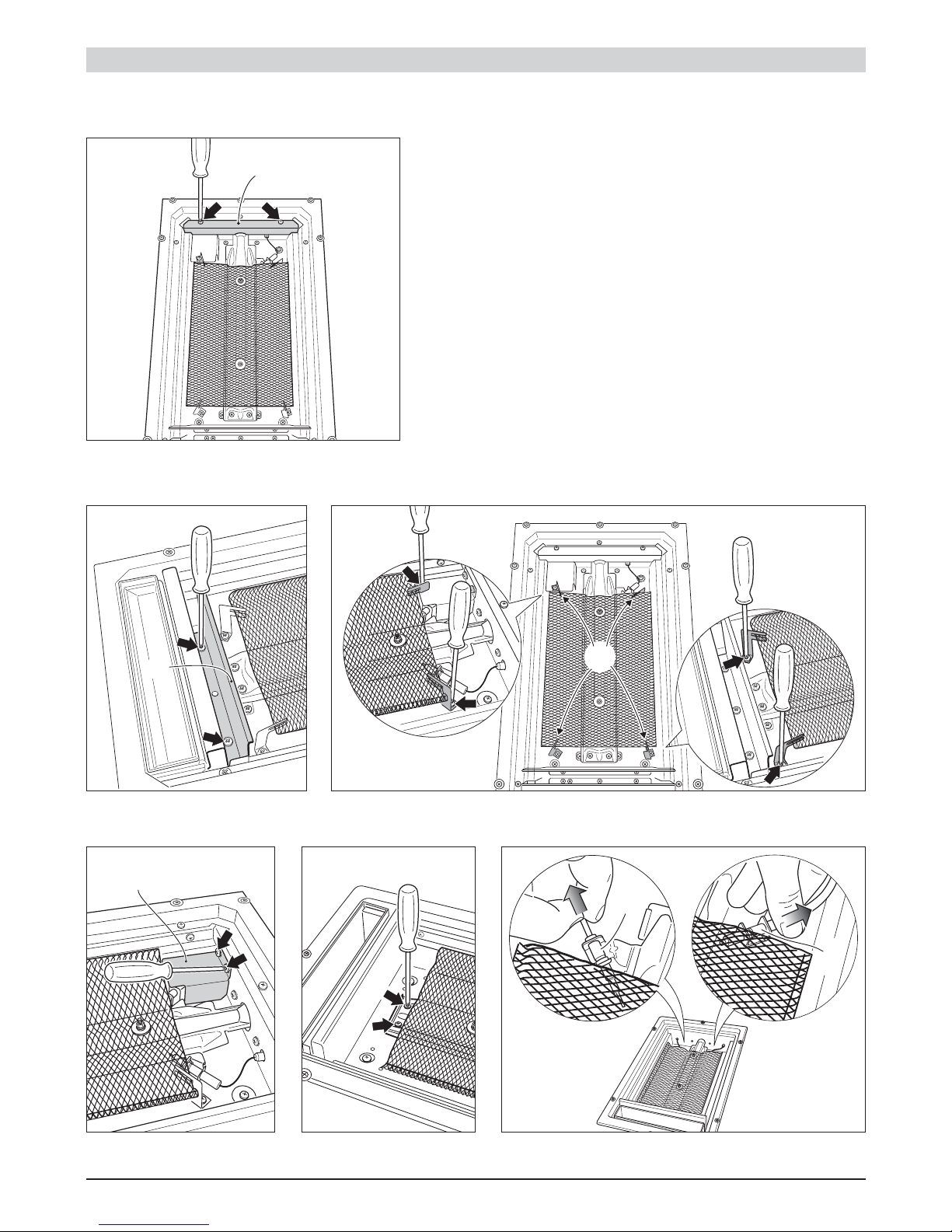
OPERATIONS TO BE EXECUTED FOR THE
REPLACEMENT OF THE INJECTOR
OF THE GRID-
DLE BURNER
■ Lift and remove the griddle stainless steel plate.
■ Unscrew the no. 2 (two) screws and remove the plate "B" (fig.
1.18).
■ Unscrew the no. 2 (two) screws and remove the shield "P" (fig.
1.19).
■ Unscrew the no. 4 (four) screws and remove the no. 4 (four) clips
"S" (fig. 1.20).
■ Unscrew the no. 2 (two) screws and remove the thermocouple
protection "T" (fig. 1.21).
■ Unscrew the no. 2 (two) burner front fixing screws (fig. 1.22).
■ Gently unlock the safety valve probe "V" and the ignition
electrode "I" (fig. 1.23). Take care not to damage the probe and
the ignition electrode.
S
Figure 1.18
B
P
T
14
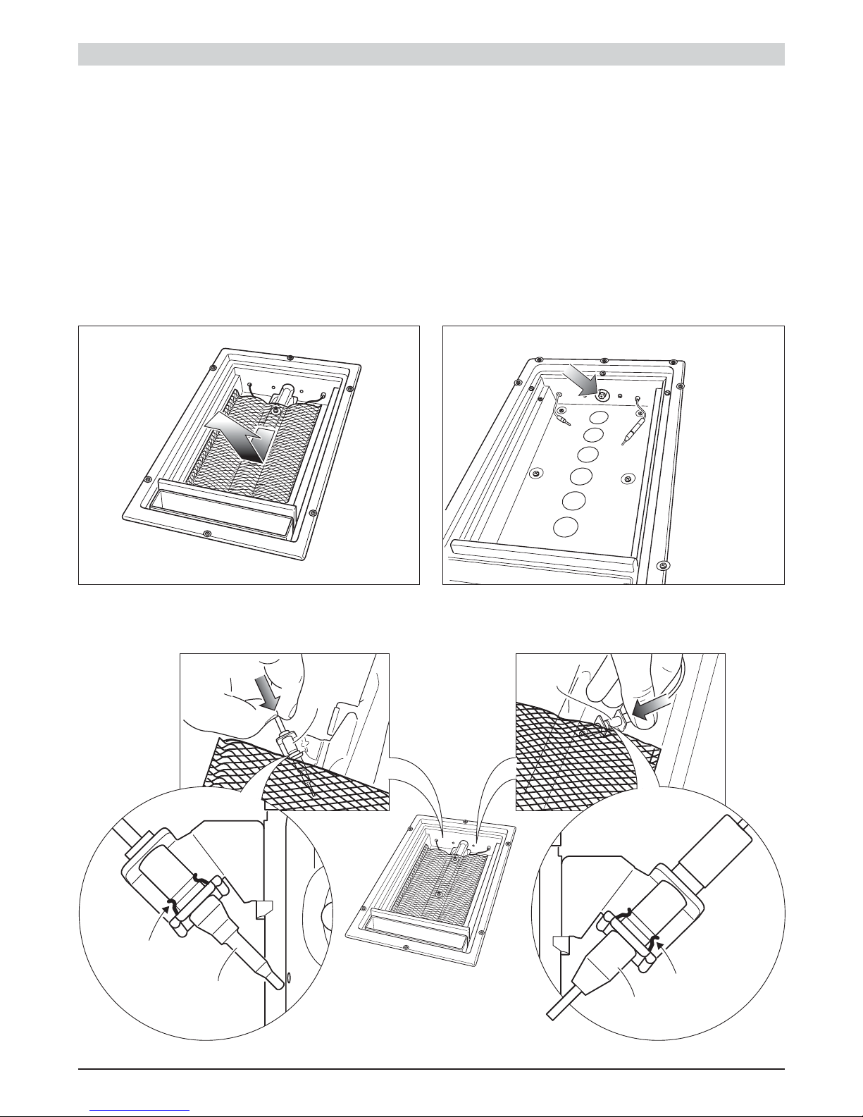
Anchorage
clip
Anchorage
clip
I
I
V
V
INSTALLATION
■ Remove the burner as shown in figure 1.24.
■ Using a 7 mm box spanner, unscrew the injector (indicated by the arrow
in fig. 1.25) and replace it by the proper one according to the kind of
gas.
■ Then replace the burner and other components repeating the above steps
in reverse order.
IMPORTANT: Pay special attention to replace correctly the safety valve
probe "V" and the ignition electrode "I" as per figures 1.26 and 1.27.
Check the correct operation of the safety valve and the ignition electrode.
Figure 1.24
Figure 1.26
Figure 1.27
Figure 1.25
15
Natural gas Universal LPG
Test Point Pressure [kPa] 1.0 2.75
BURNERS
Rapid (R) 1.45 10.30 0.91 11.20
Triple ring (TC) 1.65 13.30 0.95 11.90
Inner crown 0.85 (no. 1 central) 3.60 (*) 0.50 (no. 1 central) 3.20 (*)
Dual (D)
Outer crowns 1.15 (no. 2 outer)
16.00 (#)
0.62
(no. 2 outer) 13.00 (#)
Griddle 1.75
14.90
1.05 14.60
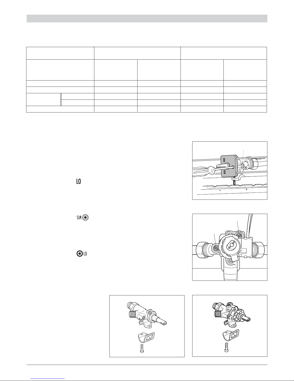
SETTING THE BURNER MINIMUM
When switching from one type of gas to another, the minimum flow rate must also be
correct: the flame should not go out even when passing suddenly from maximum to
minimum flame.
To r egulate the flame follow the instructions below:
Rapid and triple ring burners
■ Light the burner
■ Set the gas valve to position
■ Remove the knob
■ With a thin screwdriver pass by the hole of microswitch and turn the screw F
until adjustment is correct (fig. 1.28).
Inside crown of DUAL burner
■ Light the DUAL burner
■ Set the gas valve to position
■ Remove the knob
■ Using a screwdriver turn the screw H until the correct setting is obtained (fig.
1.29).
Outside crowns of DUAL burner
■ Light the DUAL burner
■ Set the gas valve to position
■ Remove the knob
■ Using a screwdriver turn the screw G until the correct setting is obtained (fig.
1.29).
For Universal LPG gas, tighten the adjustment screws completely.
F
G
H
Gas
Consumption
[MJ/h]
Injector
Orifice Dia.
[mm]
Gas
Consumption
[MJ/h]
Injector
Orifice Dia.
[mm]
LUBRICATION OF THE GAS
TAPS
■ If the gas tap becomes stiff, it is
necessary to dismantle it carefully
and clean it with petroleum spirit.
Specialist high temperature resistant grease should be used to
lubricate the tap before replacing.
■ The operations must be carried out
by an authorised person/service
agent.
Figure 1.30
Figure 1.28
Figure 1.29
INSTALLATION
TABLE FOR THE CHOICE OF THE INJECTORS
(*) Power calculated with only inner crown operating.
(#) Power calculated with inner and outer crowns operating.
Figure 1.31
Rapid and
triple ring
burners
DUAL
burner
16
CAUTION:
■ This appliance must be used only for the task it has explicitly been
designed for, that is for domestic cooking of foodstuffs. Any other form of
usage is to be considered as inappropriate and therefore dangerous.
■ Do NOT place combustible materials or products on this appliance at any
time.
■ DO NOT SPRAY AEROSOLS IN THE VICINITY OF THIS APPLIANCE
WHILE IT IS IN OPERATION.
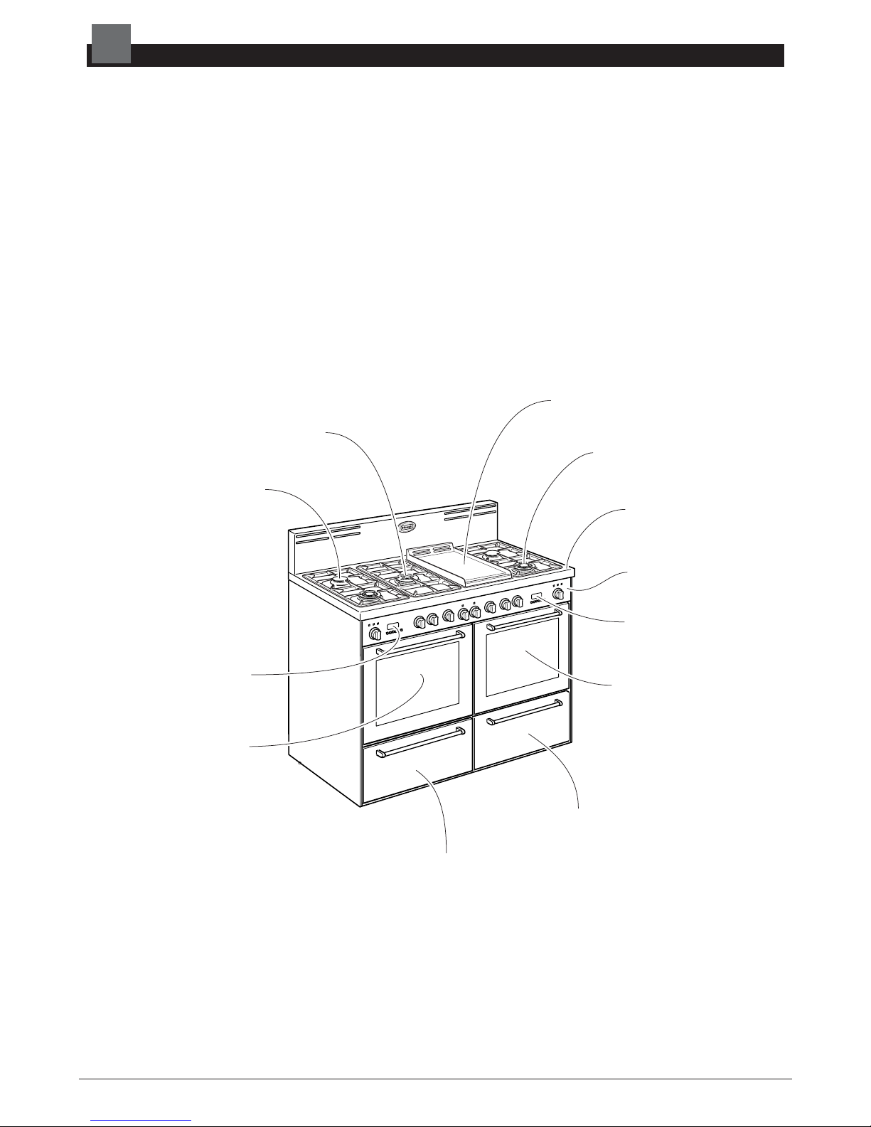
Right warming drawer
(chapter 5 - page 29)
Gas griddle
(chapter 4 - page 23)
Top burners (Rapid burner)
(chapter 3 - page 18)
Top burners (Dual burner)
(chapter 3 - page 20)
Top burners (Triple ring)
(chapter 3 - page 18)
Right self cleaning oven
(chapter 6 - page 31)
Left self cleaning oven
(chapter 6 - page 31)
Cooking hob
(page 17)
Control panel
(page 16)
Left oven
electronic programmer
(chapter 7 - page 43)
Right oven
electronic programmer
(chapter 7 - page 43)
Left warming drawer
(chapter 5 - page 29)
USE & CARE
2
Figure 2.1
17
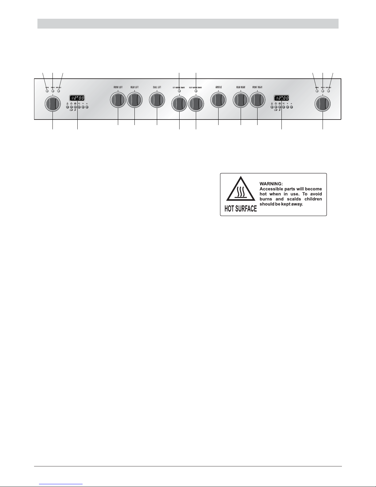
CONTROLS DESCRIPTION
Gas cooking hob controls:
1. Front left burner (2) control knob
2. Rear left burner (1) control knob
3. Central left dual burner (3) control knob
4. Central right griddle (4) control knob
5. Rear right burner (1) control knob
6. Front right burner (2) control knob
Left self cleaning oven controls:
7. Function selector control knob
8. Electronic programmer
9. Heating pilot light
10. Oven on pilot light
11. Door locked pilot light
Right self cleaning oven controls:
12. Function selector control knob
13. Electronic programmer
14. Heating pilot light
15. Oven on pilot light
16. Door locked pilot light
Left warming drawer controls:
17. Warming drawer control knob
18. Warming drawer on pilot light
Right warming drawer controls:
19. Warming drawer control knob
20. Warming drawer on pilot light
A
U
T
O
A
U
T
O
1
87
10 18 20119 15 1614
2 3
17 19
4 5 6
13 12
USE & CARE
- CONTROL PANEL
Figure 2.2
Please note: This appliance incorporates nr. 2 safety cooling fans which you will hear operating whenever
the oven or grill are in use. These fans are to reduce the external temperature of the appliance and cool the
internal components.
 Loading...