

Page 1

MoistureCheck
MOISTURE METER
Owner’s Manual
Version 2.2
For MoistureCheck Meters starting with Serial #12284
Delmhorst Instrument Co.
Rev 7
May, 2010
Page 2

TABLE OF CONTENTS
PAGE
GENERAL DESCRIPTION & FEATURES 4
OPERATING INSTRUCTIONS 5
NAVIGATION 5
INSTALLING THE BATTERY 6
TO POWER THE METER ON 7
METER USE 7
BASIC & ENHANCED MODES 7
USING THE METER IN BASIC MODE 7
To Take Pin Readings in Basic Mode 7-8
To Set the Alarm in Basic Pin Mode 8-9
To Change the Temperature Correction 9
To Take Scan Readings in Basic Mode 9-10
To Set the Alarm in Basic Scan Mode 10
To Reset the Meter to Default Settings in Basic Mode 10
USING THE METER IN ENHANCED MODE 11
Job Definition 11
To Create or Modify a Job in Pin Mode 11-12
To Set Temperature Correction 12
To Set the Alarm in Enhanced Pin Mode 13
To Take Pin Readings in Enhanced Mode 13-14
To Take Scan Readings in Enhanced Mode 14
To Set the Alarm in Enhanced Scan Mode 14-15
MAIN MENU OPTIONS 15
STORAGE 15
VIEW STATISTICS 15-16
STORED READINGS 16-18
CLEAR MEMORY 18
RESTORE DEFAULTS 18
IR LINK 18-20
SETUP MENU 20-21
TAKING A READING – PRACTICAL APPLICATIONS 22
TESTING WOOD 22
PAINT FAILURE AND MOISTURE 22-23
EIFS 23
USING THE 0-100 REFERENCE SCALE 23
Copyright 2005, Delmhorst Instrument Co.
Page 2 of 29
Page 3

TESTING CONCRETE 24
TESTING INSULATION 24-25
TESTING DRYWALL 25
CARE OF YOUR METER 26
SERVICE FOR YOUR METER 27
WARRANTY 28
SPECIES LIST 29
Copyright 2005, Delmhorst Instrument Co.
Page 3 of 29
Page 4

GENERAL DESCRIPTION/FEATURES
Thank you for your purchase of Delmhorst Instrument Co’s newly designed MoistureCheck
handheld wood moisture meter. The MoistureCheck provides the user with a host of data
acquisition capabilities, and offers the latest in features and functionality. Even with its wide
range of functions, the MoistureCheck is intuitive and easy to operate. We recommend that you
read the following pages in detail to take full advantage of all that the MoistureCheck has to
offer.
Outstanding Features:
• Pin mode
o 5%-60% wood scale (Douglas Fir)
§ Corrects for 69 individual wood species over the range of
5%-60%MC
§ Corrects for temperature over the range of 0-255F/-18-124C
o 0.1% - 6% Sheetrock® scale
o 0-100 numerical reference scale for non-wood building materials
• Scan Mode
o 0-300 numerical reference scale
• General Features:
o Integral Contact pins mounted on top of meter provide 5/16” penetration
o Connector for external Electrodes
o On-screen reading recall of up to 1400 readings
o Date and time stamp for each stored reading
o Job groupings
o Optional infrared linking capability w/ application software
o 9V battery
o 1-year warranty
o Carrying Case
Copyright 2005, Delmhorst Instrument Co.
Page 4 of 29
Page 5

OPERATING INSTRUCTIONS
-User Guide-
This guide provides step-by-step instructions on powering up, using and powering down the
meter.
NAVIGATION:
The meter uses an on-screen, menu-driven approach to navigate through the meter features,
allowing for an intuitive understanding of keypad functions. Each screen presents the user with a
number of selectable options. One of the options is always selected and the user can move
(navigate) the selection to any other available option. The keypad is aimed at providing
navigational control, and not at accessing specific features. There are four directional keys
aligned intuitively around a middle (fifth) key (see Figure 1): Above (UP), below (DOWN), to the
right (RIGHT) and to the left (LEFT). The middle key is used to SELECT the option highlighted on
the screen. For purposes of this owner’s manual, the five keys will be referred to as SELECT and
ï ð ñ ò.
Fig. 1 Keypad Layout
Copyright 2005, Delmhorst Instrument Co.
Page 5 of 29
Page 6

INSTALLING THE BATTERY:
The battery compartment is located on the underside of the case, at the bottom of the handle.
1. Open the battery compartment by sliding the lid back while pressing on the release indent.
2. Ensure correct polarity, and push the battery in flush with the bottom board until the
connectors snap together on both sides.
3. Replace the battery compartment lid.
IMPORTANT NOTE:
DO NOT REMOVE THE BATTERY WITHOUT TURNING THE METER OFF FIRST. BATTERY
REMOVAL WHILE THE METER IS ON MAY CAUSE LOSS OF STORED READINGS AND MAY
CORRUPT THE STORAGE MEMORY. IF THIS OCCURS, CERTAIN FUNCTIONS (SUCH AS
STATISTICS, READING RECALL, ETC) WILL FAIL AND LOCK UP THE METER. If the battery is
removed by accident while the meter is ON, and if the readings already stored are important, DO
NOT store additional readings. Turn the meter back on and perform a PC download. Beware that
any readings stored during the power cycle that included the battery removal WILL NOT be
available and CANNOT be recovered. Once the download is complete, perform a meter reset by
choosing “RESTORE DEFAULTS” in the Storage Menu. If a download is not necessary, go
directly to “RESTORE DEFAULTS”.
LOW BATTERY:
The meter features a battery status monitor, designed to warn the user as well as protect
measurement accuracy from impending battery failure conditions. The battery warning is
triggered by either continuous or temporary low voltage conditions. Visible (a battery icon on the
top right side of the display) and audible (buzzer warble) indicators accompany a battery warning.
Once a permanent low battery condition is detected, all measurement functions are disabled.
Enough power remains for other menu functions, including a PC download, although almost any
user action at this time causes a low-battery warning to be generated. The battery should be
replaced immediately. If the battery reaches critical levels, the meter will refuse to stay on at
power-up.
This gradual warning system is intended to provide the user advanced battery status notice and
give ample time for replacement before operational limitations occur.
NOTE: Stored readings are not lost during battery replacement or low battery conditions. Current
meter settings are maintained as well.
Copyright 2005, Delmhorst Instrument Co.
Page 6 of 29
Page 7

TO POWER THE METER ON:
To turn the meter on, press and hold the SELECT button for approx. 2 seconds.
The first screen will temporarily display the meter name and the software revision level. Refer to
this revision level whenever you call Customer Service.
The next screen is the MAIN MENU. Use ï ð ñ ò keys to select the desired function/mode
and then press SELECT to activate the function.
METER USE
BASIC AND ENHANCED MODES:
MoistureCheck may be used as a BASIC meter, which allows the user to begin taking readings
in either the scan mode or pin mode, without having to set up a job definition. BASIC mode does
not allow for data collection and is the default mode of the meter upon power up.
Or, MoistureCheck may be used in ENHANCED mode, which requires the user to set job
definitions and materials for each location within a job. The meter also stores each reading in
ENHANCED mode to allow for on screen reading recall or download to a PC.
USING THE METER IN BASIC MODE:
MoistureCheck is shipped from the factory set to BASIC mode. Use this option if you wish to use
the meter for scan or pin readings without having to set up a job.
Although Basic Mode does not allow for data acquisition, it does allow the user to set the type of
material being tested, and set the alarm to sound if a pre-established %MC is exceeded.
TO TAKE PIN READINGS IN BASIC MODE:
1. From the BASIC Main Menu, use the ò key to highlight PIN MODE. Then, use the
SELECT key to enter the pin mode.
2. The meter will display the main %MC READ screen, as shown below:
Copyright 2005, Delmhorst Instrument Co.
Page 7 of 29
Page 8

3. Use the ò key to highlight the default material (Douglas Fir) if you wish to change it
to a different material. Press the SELECT key to get into the SELECT MATERIAL sub
menu.
4. Use the ñ ò keys to highlight the material you are testing. Press the SELECT key to
choose that material. This will bring you back to the main %MC READ screen.
5. Use the ï ð keys to highlight the pin type selection. Press the SELECT key to
toggle between 4-pin (non-insulated) pins and 2-pin (insulated) pins.
You may begin taking readings by inserting the pins into the material and pressing the
SELECT key. This will display a %MC reading. If you wish to hold a reading on screen,
press the SELECT key again; otherwise remove the pins from the material being tested
and take another reading.
TO SET THE ALARM IN BASIC PIN MODE:
1. If you wish to set the alarm to beep after a pre-selected %MC value is reached, use the
ñ ò keys from the %MC screen to highlight the ALARM. Press the SELECT key to
enter the alarm sub menu.
2. The default status of the alarm is “OFF.” Press the SELECT key to turn it on.
3. After the alarm is turned on, use the ï ð keys to scroll up or down to a higher or
lower alarm value.
4. After you have selected the alarm value, use the ò key to highlight DONE. Press
SELECT to get back to the %MC READ screen.
Copyright 2005, Delmhorst Instrument Co.
Page 8 of 29
Page 9

Default alarm settings in pin mode are as follows for different materials:
All wood materials: 15%
Drywall: 1.0%
Concrete: 68 (on the 0-100 relative scale)
Note: The default alarm setting in scan mode is 300.
TO CHANGE THE TEMPERATURE CORRECTION:
MoistureCheck defaults to a temperature of 70ºF. As wood temperature increases, its electrical
resistance decreases and indicated moisture content rises. Lower wood temperatures result in
lower indicated moisture content. A correction is necessary if the wood temperature is outside
the range of 50ºF (10ºC) to 90ºF (32ºC). Set the temperature accordingly and the meter will
make the correction.
1. To change temperature, use the ï ð keys from the %MC READ screen to highlight
the TEMPERATURE, T: 70ºF. Press the SELECT button to get into the
TEMPERATURE sub menu.
2. To scroll through the temperature settings, use the ï ð keys to scroll up or down
to a higher or lower temperature value. Temperature values will change in 5°F
increments.
3. To change between ºC and ºF press SELECT key when the COMP TEMP is
highlighted.
4. After you have selected the appropriate temperature setting, use the ò key to
highlight DONE. This will bring you back to the %MC READ screen and you may begin
taking readings.
TO TAKE SCAN READINGS IN BASIC MODE:
1. From the BASIC Main Menu, use the ñ ò? key to highlight SCAN MODE. Then, use
the SELECT key to get into the SCAN mode main menu.
The meter will display the main SCAN mode main menu, as shown below:
Copyright 2005, Delmhorst Instrument Co.
Page 9 of 29
Page 10

2. You may begin taking readings by firmly pressing the back of the meter onto the
material. This will display a relative reading that ranges between 0 and 200.
TO SET THE ALARM IN BASIC SCAN MODE:
1. If you wish to set the alarm to beep after a pre-selected relative value is reached, use
the ñ ò keys from the SCAN screen to highlight the ALARM. Press the SELECT key
to enter the alarm sub menu.
2. The default status of the alarm is “OFF.” Press the SELECT key to turn it on.
3. After the alarm is turned on, use the ï ð keys to scroll up or down to a higher or
lower alarm value.
4. After you have selected the alarm value, use the ò key to highlight DONE. Press
SELECT to get back to the %MC SCAN screen.
Note: Default alarm setting for SCAN mode is 300.
TO RESET THE METER TO DEFAULT SETTINGS IN BASIC MODE:
1. Use the ï ð keys from the BASIC main menu to highlight #4: DEFAULTS. Press
the SELECT key. The meter will display the following question:
2. Use the ï ð keys to answer “YES” or “NO.” If you answer “yes,” the meter will
return to factory default settings in basic mode; i.e. Species = Douglas fir, Temperature
correction = 70 F, Alarm = OFF in pin mode. In Scan mode, Alarm = “off.”
Copyright 2005, Delmhorst Instrument Co.
Page 10 of 29
Page 11

USING THE METER IN ENHANCED MODE:
To use MoistureCheck in enhanced mode, use the ñ ò keys to highlight #3: ENHANCED.
Setting the meter to enhanced mode requires you to create job definitions and store readings as
described below.
NOTE: Although MoistureCheck’s default mode is BASIC, it will remember the mode last
saved at power off, and will remain in the saved mode at next power up.
Settings stored in each particular mode will not be affected by restoring defaults in a
different mode.
JOB DEFINITION:
Using MoistureCheck in ENHANCED mode allows you to define jobs. In this mode,
MoistureCheck also stores each reading and allows you to download the data to a PC or laptop
via Infrared connection. Jobs may be defined only when using the meter in pin mode. Scanned
readings cannot be part of a job.
TO CREATE OR MODIFY A JOB IN PIN MODE:
1. From the Enhanced Main Menu, highlight PIN MODE.
2. Use the ñ ò keys to highlight JOB. Press SELECT to enter the job sub menu.
3. Use the ðkey to change the job number. Press the ò key and highlight DONE.
Press SELECT to save that job number.
If it is a new job, the “Create Job” screen will appear as follows:
At the “Create Job” screen, you may select the material being tested, specify the
temperature at which measurements will be taken, and select an alarm value, if desired.
All parameters are alterable while taking readings in the new job, except for the species.
Copyright 2005, Delmhorst Instrument Co.
Page 11 of 29
Page 12

If the job was previously defined and used, you will be asked if you want to “Append
Data?”
Use the ï ð keys to answer “YES” or “NO.” If YES is selected, the meter will
retrieve the selected job’s settings (during this time a “PROCESSING…” message
appears) and then switch back to the Pin Mode screen with the restored settings.
If NO is selected, the meter returns to the Job sub menu.
TO SET TEMPERATURE CORRECTION:
MoistureCheck defaults to a temperature of 70ºF. As wood temperature increases, its electrical
resistance decreases and indicated moisture content rises. Lower wood temperatures result in
lower indicated moisture content. A correction is necessary if the wood temperature is outside
the range of 50ºF (10ºC) to 90ºF (32ºC). Set the temperature accordingly and the meter will
make the correction.
1. To change the temperature, use the ñ ò keys from the CREATE JOB sub menu to
highlight the temperature, T: 70ºF.
2. Press the SELECT key to enter the COMP TEMP sub menu.
3. Using the ï ð keys, scroll up or down to a higher or lower temperature value.
Temperature values will change in 5º F increments.
4. To change between C and F, press the SELECT key when the COMP TEMP is
highlighted.
Copyright 2005, Delmhorst Instrument Co.
Page 12 of 29
Page 13

TO SET THE ALARM IN ENHANCED PIN MODE:
1. If you wish to set the alarm to beep after a pre-selected value is reached, use the ò
key from the MC READ screen, highlight ALARM, and press the SELECT key to enter the
ALARM sub menu.
2. The default status of the alarm is “OFF.” Press the SELECT key to turn it on.
4. After the alarm is turned on, use the ï ð keys to scroll up or down to a higher or
lower alarm value.
5. After you have selected the alarm value, use the òkey to highlight DONE. Press
SELECT to get back to the MC READ screen
Default alarm settings in PIN mode are as follows for different materials:
All wood materials: 15%
Drywall: 1.0%
Concrete: 68 (on the 0-100 relative scale)
TO TAKE PIN READINGS IN ENHANCED MODE:
1. From the Enhanced Main Menu, use the ñ ò keys to highlight #1, PIN MODE.
2. Press the SELECT key to get into the ENHANCED READ screen. The current location
will stay the same while toggling between scan and pin modes.
This screen contains the following information: material, pin setting, temperature
correction, Job #, alarm setting, mode, and memory used.
3. Insert the pins into the material. The meter will start taking measurements in one of
the two following ways, depending on whether it is set for CONTINUOUS or
TRIGGERED mode. To choose between TRIGGERED or CONTINUOUS, use the
ñ ò and ï ð keys to highlight MODE, and then press the SELECT key to toggle
between TRIG and CONT.
Copyright 2005, Delmhorst Instrument Co.
Page 13 of 29
Page 14

• When the meter is set to Triggered mode, a single reading is taken every time
the SELECT button is pressed. Each reading is stored in memory. The last
measurement remains displayed on the screen.
• When the meter is set to Continuous mode, press SELECT key to initiate the
reading cycle. The meter keeps taking MC readings in this mode. These readings
are NOT stored until the SELECT key is pressed again. To exit continuous mode
WITHOUT STORING the current reading, press any directional key (ñ ò and
ï ð). To exit continuous mode and STORE the current reading, press the
SELECT key. Exiting continuous mode leaves the last reading on the screen. To
resume continuous mode, press the SELECT key again. Use the ñ ò and
ï ð keys to choose a different option.
4. At any time, you may modify Temperature (T).
The EXIT option in both SCAN and PIN MODE menus will cancel the measurement
process and will put the meter in the MAIN MENU.
TO TAKE SCAN READINGS IN ENHANCED MODE:
1. In the MAIN Menu, highlight option #2: SCAN
The screen will look as follows:
2. You may begin taking readings by firmly pressing the back of the meter onto the
material.
3. This will display a relative reading that ranges between 0 and 300.
TO SET THE ALARM IN ENHANCED SCAN MODE:
1. If you wish to set the alarm to beep after a pre-selected relative value is reached,
highlight option #2: SCAN MODE from the ENHANCED main menu. This will bring
you to the SCAN screen.
2. Use the ò and ð keys and highlight ALARM: OFF. Press the SELECT key to enter
the alarm sub menu.
3. The default status of the alarm is “OFF.” Press the SELECT key to turn it on.
Copyright 2005, Delmhorst Instrument Co.
Page 14 of 29
Page 15

4. After the alarm is turned on, use the ï ð keys to scroll up or down to a higher or
lower alarm value.
5. After you have selected the alarm value, use the òkey to highlight DONE. Press
SELECT to get back to the SCAN screen.
Default alarm setting for SCAN mode is 300.
MAIN MENU OPTIONS:
STORAGE:
The Storage Menu groups all meter features related to measurement storage, retrieval and
manipulation. All operations on stored readings may only be performed on a single job.
1. While in the main menu, use the arrow keys to highlight option #3 STORAGE
2. Press the SELECT key to enter the storage sub menu. There are four available
selections in this menu shown below.
View Statistics:
o This menu option selects the meter’s statistical analysis option. Selecting this option
gives the user access to two sets of statistical data. A screen shot example of the first set is
shown below:
Copyright 2005, Delmhorst Instrument Co.
Page 15 of 29
Page 16

o The first line indicates the Moisture Content (MC) job being analyzed.
o The second line shows the number of readings stored in the specific job
o The third line shows the Average MC value for all stored readings in the specific job.
o The fourth line shows the Standard Deviation for the specific job.
o The fifth line shows the Coefficient of Variation for the specific job.
o Selecting “MORE” gives the user access to the second set of statistical data.
o Selecting “DONE” returns the user to the storage menu screen.
NOTE:
The second set of calculations may require significant processing time, depending on the number
of readings stored in the specific job. The meter will display a screen with the word
“PROCESSING…” while calculations take place. User input is ignored during this time. Control is
returned to the user once the algorithm is complete and the second statistics screen is shown, as
in the example below:
o The first line indicates the specific MC job.
o The second line indicates the number of readings present in the specific job.
o The third line shows the 95% Confidence Interval for the specific job. This is the value
(+/-) away from the calculated average value within which 95% of the stored readings are
guaranteed to exist.
o The fourth line shows the value of the lowest MC reading stored in the specific job.
o The fifth line shows the value of the highest MC reading stored in the specific job.
There are no control entries present in this screen, such as “MORE”, “CANCEL” or “DONE”.
The only available option is to return to the storage menu screen, by pressing any key.
Stored Readings:
1. From the storage sub menu, use the keys to highlight “STORED READINGS.”
Press the SELECT key to enter the stored readings sub menu.
Copyright 2005, Delmhorst Instrument Co.
Page 16 of 29
Page 17
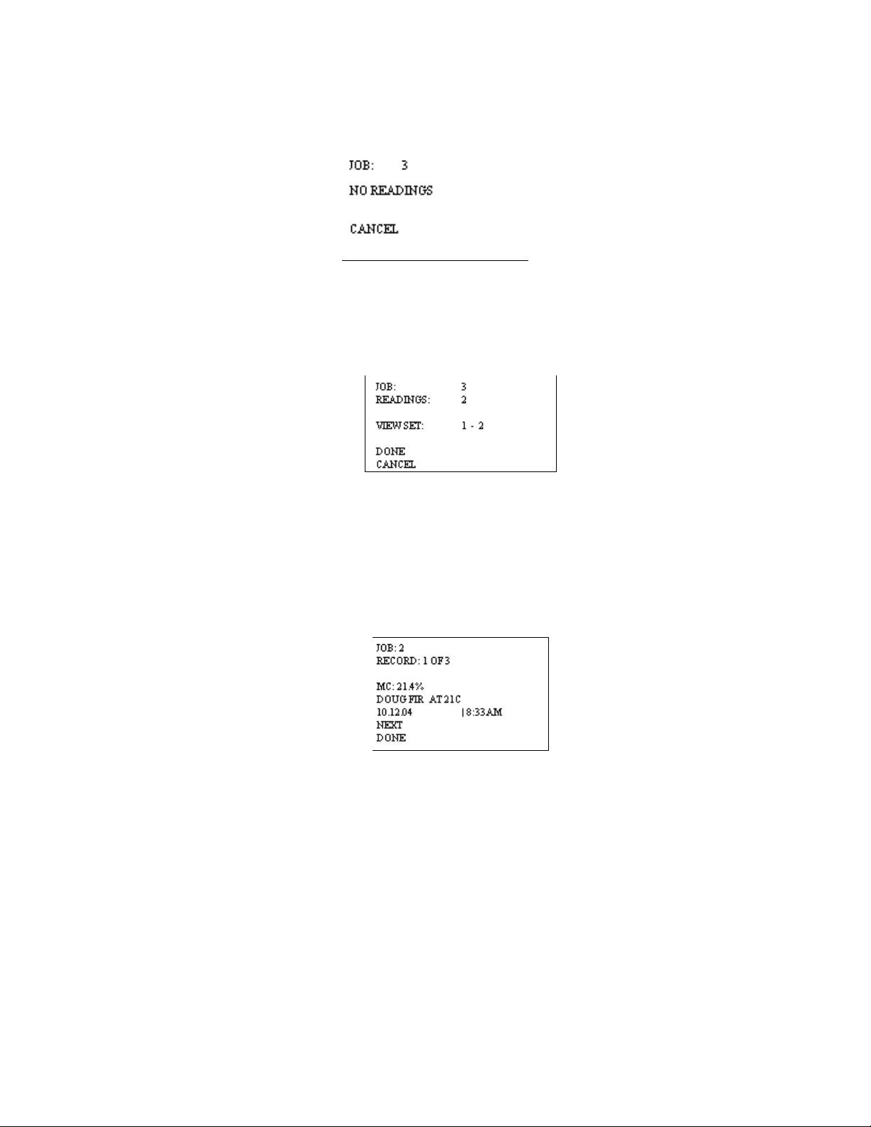
2. By using the ï ?ð keys you may select which job you wish to view. If there are no
readings in a job, the following screen will display:
If there are readings saved to a job, the following screen will display:
After you have made your job selection, scroll to DONE and press the SELECT key.
A complete record of information per reading will be displayed. You will be able to
scroll through each reading, using the NEXT key. Scroll to “DONE” if you do not wish to
see any more readings.
A selected job containing readings offers two other selectable options: “VIEW SET” and
“DONE”.
o VIEW SET: This option allows the user to view a specific range of readings in a
particular job, as opposed to the entire set, by providing a configurable start point. It
becomes useful when large numbers of readings are present in the meter. View Set
always begins by displaying “1 TO XXX”, where XXX is the maximum number of readings
in the selected job. If left unchanged, the first reading to be reviewed will be number 1.
Readings may only be reviewed in ascending sequential order.
Using the ï ?ð keys, the left-side value can be changed in increments of 10. For
example, assume the selected job contains 23 readings. The View Set entry will begin by
displaying “1 TO 23”. Successive Right button presses will yield the following: “11 TO 23”
and “21 TO 23”. At this point, the value on the left side is within 10 readings of the value
Copyright 2005, Delmhorst Instrument Co.
Page 17 of 29
Page 18

on the right side. Alternately, pressing the Left button causes the meter to subtract 10
from the current left-side value.
o DONE: Selecting this option signals to the meter that the user has completed the reading
recall setup process and is ready to begin reviewing readings.
NOTE: There may be a significant delay while the meter processes the required set of readings
for review, depending on the number of jobs present in the meter, percentage of memory space
occupied by readings, current job size and fragmentation. The meter will display a screen with the
word “PROCESSING…”. User input is ignored during this time. Control is returned to the user
once the algorithm is complete and the Retrieved Readings screen is displayed, as shown in the
example above:
Cancel: This feature returns the meter to the Storage Menu
• CLEAR MEMORY:
This option will delete all the readings stored in the meter, but will keep the defined job
structures in tact.
§ RESTORE DEFAULTS:
This will delete all defined parameters and readings stored in the meter. The meter will be
now set to the factory parameters: T = 70F, Non-insulated probe, Backlight = OFF,
Power-off time = 2 min.
Note: Memory deletion and restoring defaults are both irreversible.
§ EXIT:
This menu option returns the meter to Main Menu.
IR LINK:
This menu option initiates a wireless communication session during which the currently
stored readings will be downloaded to a PC. Before using this feature, the target PC must be
loaded with Delmhorst’s Universal Application Program and a Delmhorst base unit must be
connected to an available USB port.
Requirements:
The wireless communication technology employed in the meter requires line-of-sight access
between the red side window of the meter and the receiving window of the Base Unit. Simply
place the meter and Base Unit on a flat surface, with the red side window of the meter facing the
Copyright 2005, Delmhorst Instrument Co.
Page 18 of 29
Page 19

receiving window of the Base Unit. Separation requirements between the meter and Base Unit
are anywhere from 0 to 12 inches.
Operation:
1. Begin by starting the Delmhorst Instrument Co. Universal Application Program
(double click the application icon or choose the program from the Start Menu).
2. Once the MoistureCheck and base unit are lined up and the base unit is connected
to a USB port (a green LED should be lit), select the IR LINK option in the Main
Menu. The meter will display the message “Linking…” for a few seconds, followed
by “Link OK” when successful communication is established with the base unit. The
base unit will also indicate communication established by turning off the green LED
and turning on a red LED.
3. Press the “MANAGE DATA” button in the Delmhorst Instrument Co. Universal
Application Program. The meter will display “Data” on the screen and the base unit
will alternately turn on a yellow and red LED while data transfer takes place (red
indicates communication between the meter and Base Unit, while yellow indicates
communication between the base unit and the PC). When finished, the meter will
return to the Main Menu and the base unit will, once again, turn on its green LED. For
further details on managing the meter data in the PC please refer to the HELP
feature in the program.
NOTE: The above sequence of events in initiating communication between the PC
and the meter is not mandatory. The Application Program may be started first, or the
IR Link may be selected first. The MANAGE DATA button may also be pressed
before communication is started between the Base Unit and the meter. The meter,
base unit and Application Program all have ample delays built in to allow the other
link components to come online in any sequence.
Troubleshooting The I/R Link:
Most problems tend to occur due to the positioning of the meter relative to the base unit. There
are a few error messages that may appear on the meter’s screen:
a. Timeout: This error message occurs when too much time has passed between data
sent by the meter and the response that should have been received from the base
unit. Possible causes:
• Meter misalignment with the Base Unit (make sure the communication windows
are facing each other, within the distance indicated).
• No connection to the PC. The Base Unit must be connected to the PC through a
USB cable. Check connection.
b. KBD: This message occurs when the user presses a key during communications. Do
not push any key on the meter during data transfer. The meter interprets this as a request
to escape this activity and returns to the Main Menu. The base unit should return to a
green LED status in a few seconds. A message should appear on the PC screen as well,
indicating lost communications.
Copyright 2005, Delmhorst Instrument Co.
Page 19 of 29
Page 20

c. Sync: This message occurs when data framing is lost during data transmission. This
would only happen if the wireless link becomes unreliable. Ensure the meter and
base unit are aligned and restart the session.
d. Data E: This message occurs when the content of a correctly framed data packet is
invalid. Again, this is an unreliable wireless link problem.
NOTE: Individual records cannot be downloaded to the PC. The entire storage content is
delivered to the PC during a link session
SETUP MENU:
The Setup group of features allows access to the configurable parameters of the meter. They are:
Date and Time, Power-off time, Backlight, and Conversions (temperature mode and electrode
type). All can only be accessed in the Setup Menu. To get to the Setup Menu, use the ñ ò
keys to highlight option #5: SETUP.
SETUP MENU ENTRY DESCRIPTIONS:
o Return to Main Menu: This menu option returns the meter to Main Menu. The meter
also returns to Main Menu if no user input is detected for 20 Seconds.
o Set Date and Time: This menu option allows user access to the date and time set
screen:
The Date and Time set screen is populated with the time and date values present in the
meter at access time. UP and DOWN key action switches the row selection among available
parameters. LEFT and RIGHT key action changes the selected parameter’s value (for
“DONE” and “CANCEL” – parameters without assigned values, the LEFT and RIGHT keys
perform no function). All parameter values are incremented using the RIGHT key and
decremented using the LEFT key. The DAY parameter moves forward through weekdays
using the RIGHT key and backward using the LEFT key. The SELECT (center) key is only
active when menu selection is applied to “HOURS” (switch between standard or military
time), “DONE” or “CANCEL”. Selecting “DONE” exits this screen back to the SETUP
MENU and updates the clock with the newly chosen values. Selecting “CANCEL” exits this
screen back to the SETUP MENU without updating the clock.
Copyright 2005, Delmhorst Instrument Co.
Page 20 of 29
Page 21

o Set Power_Off time: This menu option allows the user to change the amount of time
allowed to lapse between the last key press and meter shut-down. Allowable range is
1min – 9min, with a default value of 2min.
o Set Backlight: This menu option allows the user to change the amount of time allowed to
lapse between the last key press and backlight shutdown. The default setting for this
feature is “NO”, where the backlight is completely disabled. Backlight shutdown delays
are 10, 20, 30sec. It is recommended that the backlight delay be set to the minimum
amount of time necessary in order to maximize battery life.
o Conversions: This menu option allows the user to change the temperature scale from
Fahrenheit (default) to Celsius. You can also change the electrode type from 4-pin (or
default non-insulated) to 2-pin (or insulated).
NOTE: Except for clock settings, all other parameters will return to their default values, as
indicated above, when the “RESTORE DEFAULTS” option is selected in the Storage
Menu. The values chosen for the Setup Menu parameters will remain in effect even if the
meter is turned off, and even if the battery is removed.
TAKING A READING – PRACTICAL APPLICATIONS
The following application notes are intended for use with the meter in PIN
MODE.
TESTING WOOD:
The contact pins provided are best for materials up to 6/4. On materials over 6/4 or for
hardwoods over 4/4 we recommend using a remote probe such as the 26-ES ram-type electrode.
Mount the 26-ES directly to the external connector.
⇒ Set the meter’s parameters as described previously in the owners’ manual. If the species
(construction-grade only) is unknown, set the meter to the reference calibration, Douglas Fir
and take the readings at face value.
Copyright 2005, Delmhorst Instrument Co.
Page 21 of 29
Page 22

⇒ To take a reading, align the contact pins parallel to the grain and push them to their full
penetration into the wood, if possible. Insulated pins read only at the tip and can be driven to
the desired depth.
⇒ Press the SELECT button and read the moisture content on the meter scale. The meter
displays the %MC for two seconds.
⇒ To add a reading to the previously stored readings, release the SELECT button if you are in
triggered mode. If you are in continuous mode, the meter will not store a new reading until
the SELECT button is pressed and released again during the reading cycle.
NOTE: MC RANGE AND VALID READINGS
Readings below 5% or above 60% are displayed as LOW or HIGH, respectively. However,
since the resistance of the wood also depends on the species and temperature of the wood, the
meter may not always be able to read down to 5%. For different species and different wood
temperatures, there is a minimum %MC limit below that the meter can not read. All readings
below this “lowest limit” are displayed as LOW, and are not stored. These readings are not
considered valid readings and are not used by the meter in any statistical calculations.
PAINT FAILURE AND MOISTURE
Moisture is by far the most frequent cause of paint failure. The key to preventing paint failure is to
insure that moisture is not absorbed through the wood to the back of the paint film. So, in order to
insure quality paint jobs, wood must remain dry after the application of paint.
Outdoor wood can be safely painted without danger of peeling if the %MC is 15% or less. In drier
climates, the maximum reading should be 10% to 11%. Indoor wood should be between 7% and
8% prior to painting.
The following conditions may cause high moisture content in wood:
⇒ Leaky gutters and down spouts
⇒ Leaky pipes or condensation on cold water lines in attic or hollow walls
⇒ Faulty flashing around windows, doors and where porch and dormer roofs meet sidings
⇒ End-grain wood that is not sealed with paint at all joints around windows, corners, and butt
joints
⇒ Porch columns that do not have good drainage and ventilation where they rest on porch
floors
⇒ Siding or any other wood that is in contact with the ground may absorb moisture
⇒ Siding and shingles without sufficient lap so that water is forced up through cracks by wind
pressure
⇒ Ice dams
⇒ Condensation of vapor within hollow walls
EIFS (Exterior Insulation & Finish Systems) *
Moisture intrusion problems in EIFS (also known as synthetic stucco) stem from leaking window
frames, improper use of or lack of sealant, and faulty installation of flashing.
Copyright 2005, Delmhorst Instrument Co.
Page 22 of 29
Page 23

If you suspect a problem take a visual inspection. Look for gaps around windows, doors, air
conditioning units, light fixtures, hose bibs, dryer vents and other areas of potential penetration.
Also look for visible signs of water damage. If you feel a problem exists, use the Moisture Check
with a # 21-E electrode. This electrode includes the #608 - (4") insulated pins or #608/001 (6”)
Insulated pins in EIFS Package.
Procedure:
⇒ Drill two 1/4" holes about ¾” apart at an upward 45° angle.
⇒ Push the # 21-E Electrode into the holes through the polystyrene and into the substrate.
⇒ Press the SELECT button and read the moisture content on the meter scale. The meter
displays the %MC for two seconds.
⇒ To add a reading to the previously stored readings, release the SELECT button if you are in
triggered mode. If you are in continuous mode, the meter will not store a new reading until
the SELECT button is pressed and released again during the reading cycle.
*If the sheathing is plywood, set the meter to the proper species if known. If the species is
unknown, use Douglas Fir. If the sheathing is gypsum material, set the species to Drywall.
USING 0-100 NUMERICAL REFERENCE SCALE (REL 0-100)
When taking a reading on hard materials such as concrete or masonry, set the meter to REL 0100 for a qualitative indication of the moisture level.
Make the best use of reference scale by first establishing a benchmark for the material you are
testing. Take readings in areas that you know are dry, or acceptable. Then take readings on
areas that are wet. These “dry to wet” readings can be used as reference points against which
subsequent readings are compared. Understanding the meter’s behavior on a particular material,
along with these comparative readings, your experience, and visual clues will all help determine
the overall condition. All readings should be evaluated in the light of factors such as type of paint,
type of construction, and climatic conditions.
The user-selectable alarm will sound if the displayed reading is above the alarm value.
TESTING CONCRETE SLABS FOR FLOORING APPLICATIONS
Moisture meters are an effective tool to check moisture in concrete. They can tell you where there
may be excess moisture and help determine if you need to conduct further testing.
It is important to test both the surface and mid-section of the slab, especially if the slab is on or
below grade. This will help determine if there is continuous moisture migration toward the
surface. If this condition exists, the moisture movement may be so slow that once it reaches the
surface, moisture evaporates and causes a “dry” reading when a surface test is made.
However, if a sub-surface test is made, the meter may read “wet” indicating the presence of
moisture. When the slab is covered and the upward movement of moisture continues, moisture
will move into a hygroscopic (wood) floor, or build-up pressure under a non-breathing synthetic
floor, causing delamination.
Copyright 2005, Delmhorst Instrument Co.
Page 23 of 29
Page 24

Taking a surface reading:
Drive two hardened-steel masonry nails about 3/4" apart into the finish coat of concrete floor.
Drive them about 1/8" deep so they make firm contact with the concrete and do not move when
touched.
Ø Touch the nails with the contact pins.
Ø Press The select key and read the meter. If the meter reads less than “68”, the surface
is dry. However, sub-surface tests should be made to verify if the slab is dry throughout.
Subsurface test:
Ø Drill two 1/4" holes, 3/4" apart and 1/2" to 2" deep.
Ø Drive the masonry nails into the bottom of the holes and make the tests as described
above. Nails must not touch sides of drilled holes.
If the meter still indicates a “dry” condition, the floor is ready for covering. Tests should
be made at several points, especially when the slab is thick (4” or more) and air
circulation is poor. Make tests only in newly drilled holes.
Even readings in the “wet” range can indicate relatively low moisture content in Concrete.
For example, readings in the “68 to 77” range indicate approximately 2% to 4% moisture
content.
When evaluating a slab for readiness, always consider its age, thickness, whether the
slab is on grade or suspended, whether a vapor barrier is present and the drainage
condition of the ground.
TESTING INSULATION:
⇒ Set the meter scale for the “REL 0-100” as described in the Create/Edit a Job section on
page 12.
⇒ To take a reading, attach a 21-E electrode with 4” insulated contact pins to the meter. Push
the contact pins through the Sheetrock® into the insulation behind it.
⇒ Press the SELECT button and read the moisture content on the meter scale. The meter
displays the “relative” moisture level for two seconds.
⇒ To add a reading to the previously stored readings, release the SELECT button if you are in
triggered mode. If you are in continuous mode, the meter will not store a new reading until
the SELECT button is pressed and released again during the reading cycle.
TESTING DRYWALL
⇒ Set the meter scale for Sheetrock® as described in the Create/Edit a Job section on page
12.
⇒ To take a reading, push the contact pins into the Sheetrock® to their full penetration, if
possible.
Copyright 2005, Delmhorst Instrument Co.
Page 24 of 29
Page 25

⇒ Press the SELECT button and read the moisture content on the meter scale. The meter
displays the %MC for two seconds.
⇒ To add a reading to the previously stored readings, release the SELECT button if you are in
triggered mode. If you are in continuous mode, the meter will not store a new reading until
the SELECT button is pressed and released again during the reading cycle.
Note:
Readings between 0.1% and 0.5% indicate a sufficiently dry moisture level.
Readings between 0.5% and 1% indicate a borderline situation. Readings
greater than 1% indicate material that is too wet for painting or wallpaper. A
reading above 1% also indicates enough moisture present to allow mold growth
to occur but only if other factors are also present such as a high RH level and
food source.
Copyright 2005, Delmhorst Instrument Co.
Page 25 of 29
Page 26

CARE OF YOUR METER
Ø Store your meter in a clean, dry place. The protective carrying case provided is an ideal
storage place when the meter is not in use. If the meter has been left in a hot or cold
environment overnight or for an extended period, the calibration of the pinless mode may be
adversely affected. Under these conditions, allow the meter to acclimate to the temperature
conditions in which it will be used for minimum 1-2 hours, or as long as possible.
Ø Change contact pins as needed. Keep pin retainers hand tightened.
Ø Clean the meter and contact pins with any biodegradable cleaner. Use the cleaner sparingly
and on external parts only. Keep cleaner out of the external connector.
Remove the battery if the meter will not to be used for one month or longer.
Copyright 2005, Delmhorst Instrument Co.
Page 26 of 29
Page 27

SERVICE FOR YOUR METER
Ø Before sending in your meter we recommend you give one of our trained technicians a
call. Many times troubleshooting can be taken care of over the phone. Call us at 877DELMHORST.
Ø Pack your meter securely. Enclose a purchase order or letter with a brief description of the
problem.
Ø There is no need to call us for a return authorization number if you are within the U.S.
Customers outside the U.S. must contact us for more specific instructions prior to returning a
meter.
Ø Include your name, address, daytime phone and fax numbers or e-mail address. If you
believe the meter is under warranty, please provide the original sales slip or invoice.
Ø Ship via UPS, Express Mail, Priority Mail or any overnight courier who provides prompt
service. Do not use standard parcel post.
Ø Insure your instrument for its full value and ship prepaid. We are not responsible for damage
in transit.
Ø We do not accept COD shipments or cover any incoming freight or duty charges on returned
merchandise
Ø Turnaround time on repairs is approximately two weeks.
Ø We will call you with an estimate if you specifically request one, or if we determine that the
meter may be too costly to repair.
Ø Non-warranty repairs will be returned via UPS/COD unless you have already
established other payment terms. There is no COD service outside the U.S. To pay by
credit card, include the card number and expiration date with your repair. We accept
Visa/MasterCard, American Express.
Warranty repairs will be returned at no charge if shipped within the U.S. via UPS Ground Service.
Freight charges for expedited services (i.e., Federal Express, UPS/2 Day, UPS/1 Day, etc.) are
the customer’s responsibility and will be charged as per the above terms.
Copyright 2005, Delmhorst Instrument Co.
Page 27 of 29
Page 28

WARRANTY
Delmhorst Instrument Co., referred to hereafter as Delmhorst, guarantees the MoistureCheck
meter for one year from date of purchase and any optional electrodes against defects in material
or workmanship for 90 days. If, within the warranty period of the Model MoistureCheck , you find
any defect in material or workmanship, return the meter following the instructions in the “Service
for Your Meter” section. This warranty does not cover abuse, alteration, misuse, damage
during shipment, improper service, unauthorized or unreasonable use of the meter or electrodes.
This warranty does not cover batteries, pin assemblies, or pins. If the meter or any optional
electrodes have been tampered with, the warranty shall be void. At our option, we may replace
or repair the meter.
Delmhorst shall not be liable for incidental or consequential damages for the breach of any
express or implied warranty with respect to this product or its calibration. With proper care and
maintenance the meter should stay in calibration; follow the instructions in the “Care of Your
Meter” section.
Under no circumstances shall Delmhorst be liable for any incidental, indirect, special, or
consequential damages of any type whatsoever, including, but not limited to, lost profits or
downtime arising out of or related in any respect to its meters or electrodes and no other
warranty, written, oral or implied applies. Delmhorst shall in no event be liable for any breach of
warranty or defect in this product that exceeds the amount of purchase of this product.
The express warranty set forth above constitutes the entire warranty with respect to Delmhorst
meters and electrodes and no other warranty, written, oral, or implied applies. This warranty is
personal to the customer purchasing the product and is not transferable.
Delmhorst Instrument Co.
51 Indian Lane East
Towaco NJ 07082
877-DELMHORST
www.delmhorst.com
e-mail - info@delmhorst.com
For 60 years Delmhorst has been the leading manufacturer of high quality moisture meters and
thermo-hygrometers. Today we offer the innovative KIL-MO-TROL in-kiln monitoring system. We
also offer a wide range of meters for a variety of applications including woodworking/lumber,
agriculture, construction, paper, restoration, IAQ and flooring.
510INS-0023 REV 05/2010
Copyright 2005, Delmhorst Instrument Co.
Page 28 of 29
Page 29

SPECIES LIST:
38
The following 71 species are programmed in the meter. The default species is Douglas Fir.
1 DOUGLAS FIR 37 MAGNOLIA
2 SHEETROCK®
3 REL 0-100 39 MAHOGANY, HONDURAN
4 SPF 40 MAHOGANY, PHILLIPINE
5 ALDER 41 MAPLE
6 ASH, WHITE 42 MASSARANDUBA
7 ASPEN 43 MERANTI
8 APITONG 44 MONKEY POT
9 BAMBOO 45 MYRTLE
10 BASSWOOD 46 OAK, RED
11 BEECH, EUROPEAN 47 OAK, WHITE
12 BIRCH 48 OSB
13 BUBINGA 49 PECAN
14 CEDAR, RED 50 PINE, LONGLEAF
15 CEDAR, INCENSE 51 PINE, PONDEROSA
16 CEDRELLA 52 PINE, RADIATA
17 CHERRY 53 PINE, SHORTLEAF
18 CHILEAN CHERRY 54 PINE, SOUTHERN YELLOW
19 COCOBOLO 55 PINE, SUGAR
20 COTTONWOOD 56 PINE, WHITE
21 CUMARU 57 POPLAR, YELLOW
22 CYPRESS 58 PURPLEHEART
23 EBONY, AFRICAN 59 RAMIN
24 ELM, AMERICAN 60 REDWOOD
25 FIR, RED 61 ROSEWOOD, BRAZILIAN
26 FIR, WHITE 62 RUBBERWOOD
27 GUM, BLACK 63 SPF - COFI
28 GUM, RED 64 SPRUCE, ENGLEMA
29 HACKBERRY 65 SPRUCE, SITKA
30 HEMLOCK 66 TAURAI
31 HICKORY 67 TEAK
32 IPE 68 VIROLA
33 JATOBA -Also BRAZILIAN CHERRY 69 WALNUT, BLACK
34 KERUING 70 WALNUT, BRAZILIAN
35 KOA 71 WESTERN HEMLOCK - COFI
36 LARCH
Delmhorst Instrument Co.
51 Indian Lane East
Towaco, NJ 07082-1025
Tel: 973-334-2557 / 877-DELMHORST
Fax: 973-334-2657
E-mail: info@delmhorst.com
Web site: www.delmhorst.com
MAHOGANY, AFRICAN
Copyright 2005, Delmhorst Instrument Co.
Page 29 of 29
 Loading...