

Dell XPS H233, XPS H266 User Manual

'HOO'LPHQVLRQ
6(59,&(0$18$/
;36+DQG;36+6\VWHPV
®


'HOO'LPHQVLRQ;36
6(59,&(0$18$/
+DQG;36+6\VWHPV
®

Information in this manual is subject to change without notice.
1997 Dell Computer Corporation. All rights reserved.
Reproduction in any m an ner whatsoever without the written permission of Dell Comput er Corporation is strictly forb idden.
Trademarks used in this text: Dell, the DELL logo, and Dell Dimension are registered trademarks of Dell Computer Co rporation; Intel and Pentium are registered
trademarks and MMX is a trademark of Intel Corporation; Microsoft, MS-DOS, Windows NT, and W indows are registered trademarks of Microsoft Corporation; IBM
is a registered trademark of International Business Machine s Corpo ration; VESA is a registered trademark of Video Electronics Standards Association.
Other trademarks and tr ade names may be used in this docum ent to refer to either the ent itie s cla i mi ng the marks and names or their products. Dell Computer
Corporation disclai m s a ny proprietary interest in trad emarks and trade names other th an its own.
May 1997 P/N 84980

Contents
Chapter 1
System Overview. . . . . . . . . . . . . . . . . . . . . . . . . . . . . . . 1-1
System Features . . . . . . . . . . . . . . . . . . . . . . . . . . . . . . . . . . . . . . . . . . . . . . . 1-2
Advanced Expansion Subsystem . . . . . . . . . . . . . . . . . . . . . . . . . . . . . . . 1-6
EIDE Subsystem. . . . . . . . . . . . . . . . . . . . . . . . . . . . . . . . . . . . . . . . . . . . 1-7
Hard-Disk Drive Options . . . . . . . . . . . . . . . . . . . . . . . . . . . . . . . . . . . . . 1-7
Computer Service . . . . . . . . . . . . . . . . . . . . . . . . . . . . . . . . . . . . . . . . . . . . . . 1-8
Power Supply . . . . . . . . . . . . . . . . . . . . . . . . . . . . . . . . . . . . . . . . . . . . . . 1-8
DC Power Distribution . . . . . . . . . . . . . . . . . . . . . . . . . . . . . . . . . . . . 1-9
DC Power Connector Pin Assignments . . . . . . . . . . . . . . . . . . . . . . 1-11
System Board . . . . . . . . . . . . . . . . . . . . . . . . . . . . . . . . . . . . . . . . . . . . . 1-13
Main Memory . . . . . . . . . . . . . . . . . . . . . . . . . . . . . . . . . . . . . . . . . . 1-13
System Board Jumpers . . . . . . . . . . . . . . . . . . . . . . . . . . . . . . . . . . . 1-14
Interrupt Assignments. . . . . . . . . . . . . . . . . . . . . . . . . . . . . . . . . . . . . . . . . . 1-16
DMA Channel Assignments. . . . . . . . . . . . . . . . . . . . . . . . . . . . . . . . . . . . . 1-17
Technical Specifications. . . . . . . . . . . . . . . . . . . . . . . . . . . . . . . . . . . . . . . . 1-18
Chapter 2
Basic Troubleshooting . . . . . . . . . . . . . . . . . . . . . . . . . . 2-1
Initial User Contact. . . . . . . . . . . . . . . . . . . . . . . . . . . . . . . . . . . . . . . . . . . . . 2-1
External Visual Inspection . . . . . . . . . . . . . . . . . . . . . . . . . . . . . . . . . . . . . . . 2-2
Observing the Boot Routine . . . . . . . . . . . . . . . . . . . . . . . . . . . . . . . . . . . . . . 2-3
Internal Visual Inspection. . . . . . . . . . . . . . . . . . . . . . . . . . . . . . . . . . . . . . . . 2-4
Eliminating Resource Conflicts . . . . . . . . . . . . . . . . . . . . . . . . . . . . . . . . . . . 2-5
Running the Diagnostics. . . . . . . . . . . . . . . . . . . . . . . . . . . . . . . . . . . . . . . . . 2-6
Getting Help . . . . . . . . . . . . . . . . . . . . . . . . . . . . . . . . . . . . . . . . . . . . . . . . . . 2-6
v

Chapter 3
Beep Codes and Error Messages . . . . . . . . . . . . . . . . . . 3-1
POST Beep Codes . . . . . . . . . . . . . . . . . . . . . . . . . . . . . . . . . . . . . . . . . . . . . 3-1
System Error Messages . . . . . . . . . . . . . . . . . . . . . . . . . . . . . . . . . . . . . . . . . 3-3
Chapter 4
Removing and Replacing Parts . . . . . . . . . . . . . . . . . . . 4-1
Precautionary Measures . . . . . . . . . . . . . . . . . . . . . . . . . . . . . . . . . . . . . . . . . 4-1
Computer Cover. . . . . . . . . . . . . . . . . . . . . . . . . . . . . . . . . . . . . . . . . . . . . . . 4-2
Front Bezel. . . . . . . . . . . . . . . . . . . . . . . . . . . . . . . . . . . . . . . . . . . . . . . . . . . 4-3
Drives . . . . . . . . . . . . . . . . . . . . . . . . . . . . . . . . . . . . . . . . . . . . . . . . . . . . . . . 4-4
Front-Panel Insert. . . . . . . . . . . . . . . . . . . . . . . . . . . . . . . . . . . . . . . . . . . 4-4
Drive Cage . . . . . . . . . . . . . . . . . . . . . . . . . . . . . . . . . . . . . . . . . . . . . . . . 4-5
5.25-Inch Drive . . . . . . . . . . . . . . . . . . . . . . . . . . . . . . . . . . . . . . . . . . . . 4-6
Upper 3.5-Inch Drive . . . . . . . . . . . . . . . . . . . . . . . . . . . . . . . . . . . . . . . . 4-7
Lower 3.5-Inch Drive (Mini Tower Computer Only) . . . . . . . . . . . . . . . 4-8
3.5-Inch Diskette Drive . . . . . . . . . . . . . . . . . . . . . . . . . . . . . . . . . . . . . . 4-9
Primary Hard-Disk Drive. . . . . . . . . . . . . . . . . . . . . . . . . . . . . . . . . . . . 4-10
Secondary Hard-Disk Drive. . . . . . . . . . . . . . . . . . . . . . . . . . . . . . . . . . 4-11
Power Supply . . . . . . . . . . . . . . . . . . . . . . . . . . . . . . . . . . . . . . . . . . . . . . . . 4-13
Microprocessor Fan Assembly. . . . . . . . . . . . . . . . . . . . . . . . . . . . . . . . . . . 4-14
Card Guide Assembly . . . . . . . . . . . . . . . . . . . . . . . . . . . . . . . . . . . . . . . . . 4-15
Control Panel Board. . . . . . . . . . . . . . . . . . . . . . . . . . . . . . . . . . . . . . . . . . . 4-16
System Board Components . . . . . . . . . . . . . . . . . . . . . . . . . . . . . . . . . . . . . 4-17
Expansion Cards. . . . . . . . . . . . . . . . . . . . . . . . . . . . . . . . . . . . . . . . . . . 4-18
SIMMs . . . . . . . . . . . . . . . . . . . . . . . . . . . . . . . . . . . . . . . . . . . . . . . . . . 4-19
SEC Cartridge and Heat Sink Assembly . . . . . . . . . . . . . . . . . . . . . . . . 4-20
Battery . . . . . . . . . . . . . . . . . . . . . . . . . . . . . . . . . . . . . . . . . . . . . . . . . . 4-21
System Board . . . . . . . . . . . . . . . . . . . . . . . . . . . . . . . . . . . . . . . . . . . . . . . . 4-22
Appendix A
System Setup Program . . . . . . . . . . . . . . . . . . . . . . . . . .A-1
System Setup Screens. . . . . . . . . . . . . . . . . . . . . . . . . . . . . . . . . . . . . . . . . . .A-1
Main Screen . . . . . . . . . . . . . . . . . . . . . . . . . . . . . . . . . . . . . . . . . . . . . . .A-2
IDE Device Configuration Submenu . . . . . . . . . . . . . . . . . . . . . . . . .A-4
Boot Options Submenu . . . . . . . . . . . . . . . . . . . . . . . . . . . . . . . . . . .A-5
vi

Advanced Screen . . . . . . . . . . . . . . . . . . . . . . . . . . . . . . . . . . . . . . . . . . .A-7
Peripheral Configuration Submenu . . . . . . . . . . . . . . . . . . . . . . . . . .A-8
Chipset Configuration Submenu. . . . . . . . . . . . . . . . . . . . . . . . . . . .A-10
Plug and Play Configuration Submenu. . . . . . . . . . . . . . . . . . . . . . .A-11
Security Screen . . . . . . . . . . . . . . . . . . . . . . . . . . . . . . . . . . . . . . . . . . . .A-12
Power Screen . . . . . . . . . . . . . . . . . . . . . . . . . . . . . . . . . . . . . . . . . . . . .A-13
Exit Screen . . . . . . . . . . . . . . . . . . . . . . . . . . . . . . . . . . . . . . . . . . . . . . .A-15
Index
Figures
Figure 1-1. Computer Orientation . . . . . . . . . . . . . . . . . . . . . . . . . . . . . . . 1-3
Figure 1-2. Desktop Computer Features. . . . . . . . . . . . . . . . . . . . . . . . . . . 1-4
Figure 1-3. Mini Tower Computer Features. . . . . . . . . . . . . . . . . . . . . . . . 1-5
Figure 1-4. Back-Panel Features (Typical). . . . . . . . . . . . . . . . . . . . . . . . . 1-6
Figure 1-5. DC Power Cables. . . . . . . . . . . . . . . . . . . . . . . . . . . . . . . . . . . 1-9
Figure 1-6. DC Power Distribution. . . . . . . . . . . . . . . . . . . . . . . . . . . . . . 1-10
Figure 1-7. DC Power Connector P1 . . . . . . . . . . . . . . . . . . . . . . . . . . . . 1-11
Figure 1-8. DC Power Connectors P2, P3, P4, P5, and P6. . . . . . . . . . . . 1-12
Figure 1-9. DC Power Connector P7 . . . . . . . . . . . . . . . . . . . . . . . . . . . . 1-12
Figure 1-10. System Board Features. . . . . . . . . . . . . . . . . . . . . . . . . . . . . . 1-13
Figure 1-11. System Board Jumpers. . . . . . . . . . . . . . . . . . . . . . . . . . . . . . 1-14
Figure 4-1. Computer Cover Removal . . . . . . . . . . . . . . . . . . . . . . . . . . . . 4-2
Figure 4-2. Front-Bezel Removal (Mini Tower Chassis). . . . . . . . . . . . . . 4-3
Figure 4-3. Front-Bezel Removal (Desktop Chassis). . . . . . . . . . . . . . . . . 4-3
Figure 4-4. Front-Panel Insert Removal . . . . . . . . . . . . . . . . . . . . . . . . . . . 4-4
Figure 4-5. Drive Cage Removal . . . . . . . . . . . . . . . . . . . . . . . . . . . . . . . . 4-5
Figure 4-6. 5.25-Inch Drive Removal. . . . . . . . . . . . . . . . . . . . . . . . . . . . . 4-6
Figure 4-7. Upper 3.5-Inch Drive Removal . . . . . . . . . . . . . . . . . . . . . . . . 4-7
Figure 4-8. Lower 3.5-Inch Drive Removal
(Mini Tower Computer Only) . . . . . . . . . . . . . . . . . . . . . . . . . 4-8
Figure 4-9. 3.5-Inch Diskette Drive Removal . . . . . . . . . . . . . . . . . . . . . . 4-9
Figure 4-10. Primary Hard-Disk Drive Removal . . . . . . . . . . . . . . . . . . . . 4-10
Figure 4-11. Secondary Hard-Disk Drive Assembly Removal . . . . . . . . . 4-11
Figure 4-12. Secondary Hard-Disk Drive Removal . . . . . . . . . . . . . . . . . . 4-12
Figure 4-13. Power Supply Removal . . . . . . . . . . . . . . . . . . . . . . . . . . . . . 4-13
vii

Figure 4-14. Microprocessor-Fan Assembly Removal . . . . . . . . . . . . . . . 4-14
Figure 4-15. Card-Guide Assembly Removal . . . . . . . . . . . . . . . . . . . . . . 4-15
Figure 4-16. Control-Panel Board Removal . . . . . . . . . . . . . . . . . . . . . . . 4-16
Figure 4-17. System Board Components . . . . . . . . . . . . . . . . . . . . . . . . . . 4-17
Figure 4-18. Expansion Card Removal . . . . . . . . . . . . . . . . . . . . . . . . . . . 4-18
Figure 4-19. SIMM Removal. . . . . . . . . . . . . . . . . . . . . . . . . . . . . . . . . . . 4-19
Figure 4-20. SIMM Replacement. . . . . . . . . . . . . . . . . . . . . . . . . . . . . . . . 4-19
Figure 4-21. SEC Cartridge and Heat Sink Removal. . . . . . . . . . . . . . . . . 4-20
Figure 4-22. Battery Removal . . . . . . . . . . . . . . . . . . . . . . . . . . . . . . . . . . 4-21
Figure 4-23. System Board Removal. . . . . . . . . . . . . . . . . . . . . . . . . . . . . 4-22
Figure 4-24. System Board Mountings . . . . . . . . . . . . . . . . . . . . . . . . . . . 4-23
Figure 4-25. Guide-Bracket Assembly Removal. . . . . . . . . . . . . . . . . . . . 4-24
Figure A-1. Main Screen. . . . . . . . . . . . . . . . . . . . . . . . . . . . . . . . . . . . . . .A-2
Figure A-2. IDE Device Configuration Submenu. . . . . . . . . . . . . . . . . . . .A-4
Figure A-3. Boot Options Submenu . . . . . . . . . . . . . . . . . . . . . . . . . . . . . .A-5
Figure A-4. Advanced Screen. . . . . . . . . . . . . . . . . . . . . . . . . . . . . . . . . . .A-7
Figure A-5. Peripheral Configuration Submenu. . . . . . . . . . . . . . . . . . . . .A-8
Figure A-6. Chipset Configuration Submenu . . . . . . . . . . . . . . . . . . . . . .A-10
Figure A-7. Plug and Play Configuration Submenu . . . . . . . . . . . . . . . . .A-11
Figure A-8. Security Screen . . . . . . . . . . . . . . . . . . . . . . . . . . . . . . . . . . . A-12
Figure A-9. Power Screen. . . . . . . . . . . . . . . . . . . . . . . . . . . . . . . . . . . . .A-13
Figure A-10. Exit Screen. . . . . . . . . . . . . . . . . . . . . . . . . . . . . . . . . . . . . . .A-15
Tables
Table 1-1. DC Voltage Ranges. . . . . . . . . . . . . . . . . . . . . . . . . . . . . . . . . 1-8
Table 1-2. System-Board Jumper Descriptions . . . . . . . . . . . . . . . . . . . 1-15
Table 1-3. Interrupt Assignments . . . . . . . . . . . . . . . . . . . . . . . . . . . . . . 1-16
Table 1-4. DMA Channel Assignments . . . . . . . . . . . . . . . . . . . . . . . . . 1-17
Table 1-5. Technical Specifications . . . . . . . . . . . . . . . . . . . . . . . . . . . . 1-18
Table 3-1. POST Beep Codes. . . . . . . . . . . . . . . . . . . . . . . . . . . . . . . . . . 3-2
Table 3-2. System Error Messages . . . . . . . . . . . . . . . . . . . . . . . . . . . . . . 3-3
Table A-1. Main Screen Categories. . . . . . . . . . . . . . . . . . . . . . . . . . . . . .A-2
Table A-2. IDE Device Configuration Submenu Categories . . . . . . . . . .A-4
Table A-3. Boot Options Submenu Categories . . . . . . . . . . . . . . . . . . . . .A-5
Table A-4. Advanced Screen Categories. . . . . . . . . . . . . . . . . . . . . . . . . .A-7
Table A-5. Peripheral Configuration Submenu Categories. . . . . . . . . . . .A-8
viii
Table A-6. Chipset Configuration Submenu Categories . . . . . . . . . . . . . A-10
Table A-7. Plug and Play Configuration Submenu Categories . . . . . . . . A-11

Table A-8. Security Screen Categories . . . . . . . . . . . . . . . . . . . . . . . . . .A-12
Table A-9. Power Screen Categories . . . . . . . . . . . . . . . . . . . . . . . . . . . .A-13
Table A-10. Exit Screen Categories. . . . . . . . . . . . . . . . . . . . . . . . . . . . . .A-15
ix

ead This First
R
A prerequisite for using this manual to service Dell computer systems is a
basic knowledge of IBM®-compatible PCs and prior training in IBMcompatible PC troubleshooting techniques. In addition to information
provided in this manual and the online System User’s Guide that came with
the syste m, Dell provides the Diagnostics and Troubleshooting Guide for
troubleshooting procedures and instructions on using the Dell diagnostics to
test the computer system.
arnings, Cautions, and Notes
W
Throughout this manual, there may be blocks of text printed in bold type or in
italic type. These blocks are warnings, cautions, and notes, and they are used as
follows:
WARNING: A WARNING indicates the potential for bodily harm and provides instructions for how to avoid the problem.
CAUTION: A CAUTION indicates either potential damage to hardware or
loss of data and provides instructions for how to avoid the problem.
NOTE: A NOTE provides helpful information about using the computer system.
x

Chapter 1
System Overview
he Dell Dimension® XPS H233 and XPS H266 systems are high-speed,
T
single-processor computer systems that use an Intel® Pentium® II microprocessor with MMX™ technology. These Dell® systems incorporate an ISA
expansion bus as well as a high-performance PCI local bus. These buses are
built into the system board, which also integrates all other elements of the basic
computer system.
The Dell Dimension XPS H233 and XPS H266 systems are available in either a
desktop or a mini tower configuration. Both configurations use the same system
board and base chassis. The only difference, other than physical mounting, is
the number of externally-accessible 3.5-inch drive bays.
The Dell Dimension XPS H233 system operates at an internal frequency of
233 MHz and an external frequency of 66 MHz. The Dell Dimension XPS
H266 system operates at an internal frequency of 266 MHz and an external frequency of 66 MHz. A single-edge contact (SEC) cartridge connected to the
system board contains the system’s microprocessor and cache circuitry.
Main memory consists of two or four EDO SIMMs arranged in pairs. The base
configuration for main memory is two 16-MB nonparity SIMMs. Main memory
can be expanded up to 128 MB using 16- or 32-MB SIMMs.
The front of the computer has two 5.25-inch drive bays, one (desktop system) or
two (mini tower system) 3.5-inch drive bay(s), plus a 3.5-inch diskette-drive
bay . The 5.25-inch and 3.5-inch drive bays can hold diskette drives, tape drives,
or CD-ROM drives.
System Overvi ew 1-1

S
ystem Features
In addition to the standard features found in a traditional PC, the Dell
Dimension XPS H233 and XPS H266 systems include the following new and/or
advanced features:
An Intel Pentium II microprocessor with MMX technology, specifically
•
designed to handle complex multimedia and communications software.
Secondary cache of 512 KB of SRAM included within the SEC cartridge.
•
Main memory consisting of 32 to 128 MB of high-speed EDO SIMMs.
•
Error correction code (ECC) support built into the system board that co r r e c ts
•
single-bit errors and detects all multiple-bit errors when parity SIMMs are
installed.
Three 32-bit PCI expansion-card slots and two 16-bit ISA expansion-card
•
slots. One shared expansion-card slot can accept either a PCI or an ISA
expansion card.
Support for SCSI hard-disk drives and CD-ROM drives when a SCSI
•
controller card is installed in an expansion-card slot.
A high-speed, high-resolution PCI video controller card installed in an
•
expansion-card slot, rather than an integrated video controller, to provide
video flexibility for customers.
A 16-bit integrated audio controller that provides sound functions com-
•
patible with a Sound Blaster Pro expansion card.
A MIDI/game port for connecting a MIDI device, joystick, game pad, or
•
other game input device.
An integrated high-performance serial port and a bidirectional parallel port.
•
Two USB connectors, which can simplify connecting peripheral devices.
•
Most of these features are briefly described in this chapter. For a complete list
of system features, see “Technical Specifications” found later in this chapter.
When following the procedures in this manual, assume that the locations or
directions relative to the computer are as shown in Figure 1-1.
NOTE: Some service procedur es r ecommend laying the mini tower computer on
its right side to improve service access, but the descriptions in this manual continue to use the directions shown in Figure 1-1 for the mini tower computer.
1-2 Dell Dimension XPS H233 and XPS H266 Systems Service Manual
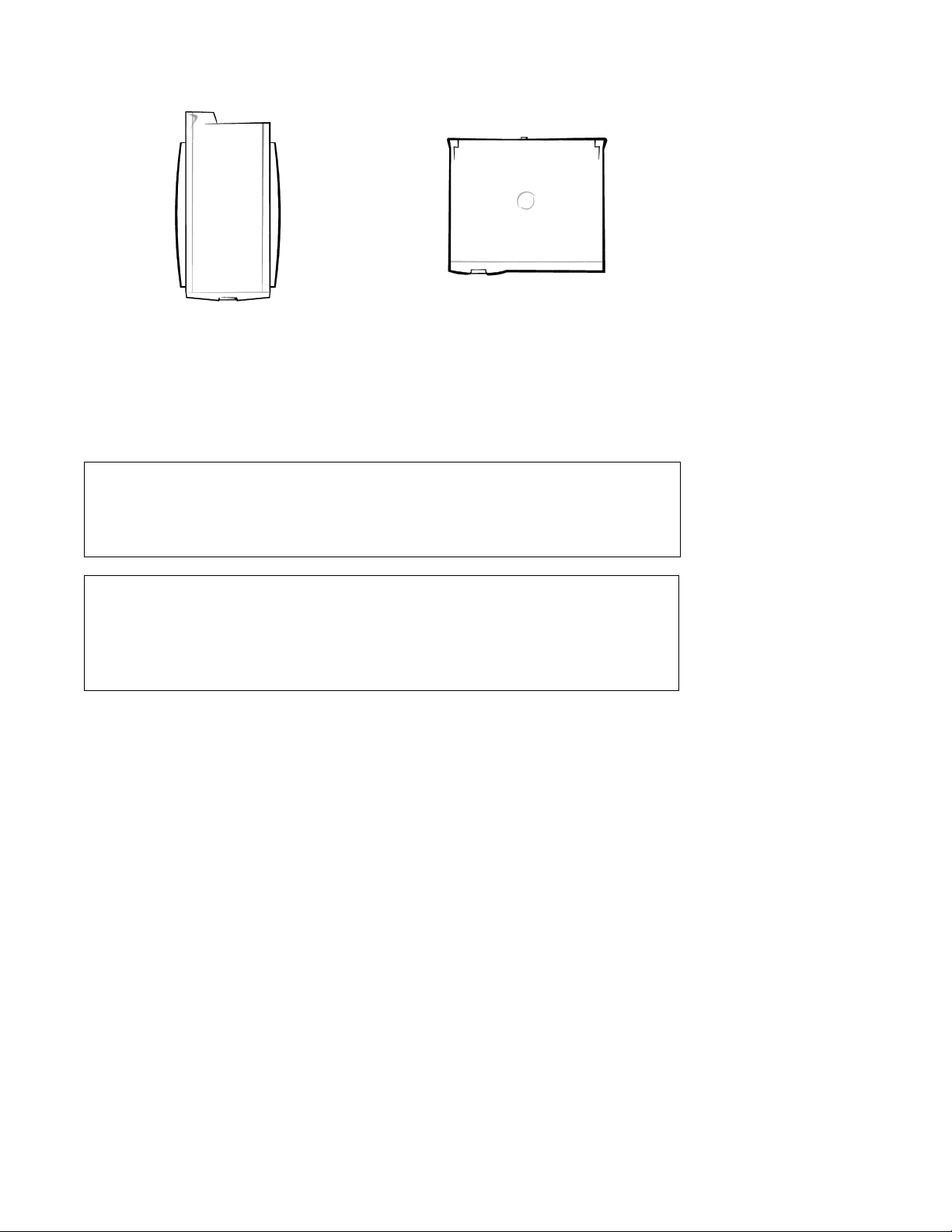
back
back
left side right side
front
Mini Tower Computer
left side right
front
Desktop Computer
Figure 1-1. Computer Orientation
CAUTION: To avoid possible data or file structure corruptions, the reset
button should only be used when the system cannot be rebooted by pressing <Ctrl><Alt><Del>. Before you use the reset button to initiate a
hardware reset, close any op en application programs and files if possible.
CAUTION: Ensure that all expansion-card slots have either a cardmounting bracket or a metal filler bracket installed. Ensure that the
unoccupied drive bays have a front-panel insert installed. Omitting these
inserts or brackets can disturb the normal airflow in the computer,
resulting in possible damage to system components.
System Overvi ew 1-3

microprocessor fan
power supply
system board
expansion-card
slots
card guide assembly
and primary hard-disk drive
secondary hard-disk
drive bracket
drive cage
drive bays
(typical)
3.5-inch
diskette drive
power button
hard-disk drive
access indicator
reset button
front bezel
Figure 1-2. Desktop Computer Featur es
1-4 Dell Dimension XPS H233 and XPS H266 Systems Service Manual

microprocessor fan
power supply
system board
expansion-card
slots
card guide assembly
and primary hard-disk drive
secondary hard-disk
drive bracket
drive cage
drive bays
(typical)
3.5-inch
diskette drive
power button
hard-disk drive
access indicator
reset button
front bezel
Figure 1-3. Mini Tower Computer Features
System Overvi ew 1-5

voltage
selection
switch
security
cable ring
parallel port
connector
MIDI/game port
connector
video
connector
AC power
receptacle
mouse
connector
keyboard
connector
serial port
connector
USB
connectors (2)
line-out
connector
microphone
connector
line-in
connector
Figure 1-4. Back-Panel Features (Typical)
Advanced Expansion Subsystem
This computer system offers an advanced expansion subsystem that can support
a mixture of traditional ISA expansion cards (called legacy expansion cards),
Plug and Play ISA expansion cards, and PCI expansion cards. Either the operating system or the ISA Configuration Utility (ICU) provides the means to
configure the various types of expansion cards and to avoid resource conflicts
that might arise.
NOTES: The ICU is required only when the system runs a non-Plug-and-Play
operating system (such as Microsoft® Windows NT® 4.0 and earlier) and
includes legacy ISA expansion cards. With the Microsoft Windows® 95 operating system, the functions provided by the ICU are handled by the Device
Manager, which can be accessed by double-clicking the System icon in the
Control Panel. Windows 95 documentation provides instructions on using the
Device Manager to manage resources and resolve conflicts.
Because Dell ships only Plug and Play and PCI expansion cards on Dell
Dimension systems that have a non-Plug-and-Play operating system, the ICU is
not provided with systems. This utility can be downloaded from Dell’s online
services.
After all legacy expansion cards have been configured by the operating system
or with the ICU, the system automatically assigns any required memory space,
IRQ lines, and DREQ lines to any installed Plug and Play and PCI expansion
cards the next time the system is booted.
1-6 Dell Dimension XPS H233 and XPS H266 Systems Service Manual

Chapter 2, “Using Configuration Software,” in the Reference Guide and the
“Configuring Expansion Cards” section in the online System User’s Guide
(located in the Dell Accessories folder) provide instructions for using the ICU
to configure legacy ISA expansion cards.
The expansion-card slots include three ISA expansion-card connectors and four
PCI expansion-card connectors. One PCI expansion-card connector and one
ISA expansion-card connector share a single expansion-card slot, so a maximum of six expansion cards can be installed.
EIDE Subsystem
The EIDE subsystem includes two EIDE interfaces (primary and secondary),
each of which can support up to two EIDE devices such as high-capacity EIDE
hard-disk drives, CD-ROM drives, and tape drives.
When two EIDE drives are connected to a single EIDE interface cable, a
master/slave relationship must be defined between the two drives so that they
will operate correctly while cabled together. Assigning the master and slave
designations usually involves resetting jumpers on the circuit card on the underside of each drive. The master/slave relationship is defined in different ways for
different types of drives. For details about a specific drive, refer to the documentation included with the drive. When you replace a drive, look at the
jumpers on the removed drive to set the jumpers on the replacement drive.
NOTE: The externally accessible drive bays at the front of the computer are
normally used for diskette drives, CD-ROM drives, or tape drives. The harddisk drives should be installed in the internal drive bays as described in the
following subsection. For detailed information about the data storage subsystem, see “Installing Drives” in the online System User’s Guide, which is
located in the Dell Accessories folder.
Hard-Disk Drive Options
A 1-inch-high EIDE or SCSI hard-disk drive is installed in the primary harddisk drive bay in the card guide assembly at the front of the chassis. An optional
1-inch-high EIDE or SCSI hard-disk drive can be installed in the secondary
hard-disk drive bay located near the 3.5-inch diskette drive. SCSI hard-disk
drives require a SCSI controller card installed in an expansion-card slot.
System Overvi ew 1-7

C
omputer Service
The following subsections provide service-related information about the
computer.
Power Supply
The 200-W power supply can operate from an AC power source of 115 VAC at
60 Hz or 230 VAC at 50 Hz. The power supply provides the DC operating voltages and currents listed in Table 1-1.
NOTE: The power supply produces DC voltages only under its loaded condition. The DC power cable connectors must be connected to their corresponding
power input connectors on the system board or drives in order to measure these
voltages.
Table 1-1. DC Voltage Ranges
Maximum
Voltage Range
Output Current
+3.3 VDC +3.14 to +3.47 VDC
+5 VDC +4.90 to +5.25 VDC
14.00 A
22.00 A
1
1
–5 VDC –4.50 to –5.50 VDC 0.300 A
+12 VDC +11.40 to +12.60 VDC
6.00 A
2
–12 VDC –10.80 to –13.20 VDC 0.300 A
+5 VSB
1
2
3
3
The combined load on the +3.3 VDC and +5 VDC outputs cannot exceed 140 W.
The +12-VDC output line can withstand surges of up to 11.0 A to support disk start-up
operations.
The +5 VSB (volts standby) is sometimes called “flea power.”
+4.75 to +5.25 VDC 0.010 A
1-8 Dell Dimension XPS H233 and XPS H266 Systems Service Manual

DC Power Distribution
Figures 1-5 through 1-9 provide the following information about DC power
distribution:
Power-supply cable identification
•
Typical DC power connections for diskette, tape, CD-ROM, and hard-disk
•
drives
Power distribution to sockets and connectors on the system board
•
Pin assignments of DC power connectors
•
P4
P5
P6
P3
Figure 1-5. DC Power Cables
P1
P7
P2
System Overvi ew 1-9

power
supply
J9D1
J7J2
J7J1
J6J2
3.3 VDC
GND
PWRGOOD
+12 VDC
+5 VDC
–5 VDC
+5 VDC
GND
+5 VSB
PSON#
power
switch
P1
POWER
PSON#
GND
+5 VDC
GND
+5 VDC
GND
+5 VDC
GND
GND
+5 VSB
GND
+5 VDC
–5 VDC
–12 VDC
+12 VDC
P7
J7M1
P6
battery
P2
P3
P5
P4
5.25-inch
drive
5.25-inch
drive
3.5-inch drives
(second drive
uses Y-cable)
3.5-inch
diskette drive
primary
hard-disk drive
secondary
hard-disk drive
(uses Y-cable)
RTC
ISA
connectors
PCI
connectors
J6J1
2.1–2.8 V
converter
CPU/system
logic
+5 VDC
GND
1.5-V
converter
+2.1–2.8 VDC
+1.5 VDC
GND
system board
fuse
fuse
Figure 1-6. DC Power Distribution
1-10 Dell Dimension XPS H233 and XPS H266 Systems Service Manual
GND
+5 VDC
GND
+5 VDC
GND
+5 VDC USB
GND
+12 VDC
KEYBRD
MOUSE
J8L1

DC Power Connector Pin Assignments
The power-supply output voltages can be measured at the back (wire side) of
the DC power connectors without disconnecting them. Figures 1-7 through 1-9
show the wire side of the connectors.
–5 VDC (white)
common (black)
common (black)
common (black)
2
PSON#
(brown)
11
12 13 14 15 16 17 18 19 20
+5 VDC (red)
+5 VDC (red)
+5 VDC (red)
not connected
+5 VDC (red)
P1
1
2 345678910
+5 VDC (red)
common (black)
+5 VDC (red)
common (black)
PWRGOOD
1
(gray)
common (black)
common (black)
–12 VDC (blue)
+12 VDC (yellow)
+5 VFP (purple)
1 Pin 5 — PWRGOOD is a status signal generated by the power supply to notify the system
that the DC operating voltages are within the ranges required for proper system operation.
2 Pin 11 — PSON# is activated by pressing and releasing the power button while the power
supply is in its standby state. This act ion connects the power supply’s PSON# input to
ground, thereby switching the power supply to its full-on condition.
Figure 1-7. DC Power Connector P1
System Overvi ew 1-11

P2, P3,
P5, P6
1234
+5 VDC (red)
common (black)
common (black)
+12 VDC (yellow)
P4
1234
+5 VDC (red)
common (black)
common (black)
+12 VDC (yellow)
Figure 1-8. DC Power Connectors P2, P3, P4, P5, and P6
P7
456
321
+3.3 VDC (orange)common (black)
+3.3 VDC (orange)common (black)
common (black) +3.3 VDC (orange)
Figure 1-9. DC Power Connector P7
1-12 Dell Dimension XPS H233 and XPS H266 Systems Service Manual

System Board
The subsections that follow provide service-related information about system
board components.
mouse connector
(MOUSE)
keyboard connector
(KEYBRD)
USB connectors
(USB)
serial port
connector (SER1)
parallel port
connector (PARALLEL)
integrated audio
controller jacks
(LINE OUT, LINE
IN, and MIC IN)
MIDI/game port
(GAME/AUDIO)
CD-ROM drive
audio cable
connector (CDROM)
PCI expansion-card
connectors (PCI1,
PCI2, PCI3, and PC I4)
ISA expansion-card
connectors (ISA1,
ISA2, and ISA3)
SEC cartridge
connector (SLOT 1)
power input connector
(POWER)
SIMM sockets
(J6J1, J6J2, J7J1, and J7J2)
3.3-V power
input connector
(J7M1)
battery socket (BT9M1)
microprocessor fan
connector (J8L1)
primary EIDE channel
connector (PRI IDE)
diskette-drive interface
connector (FLOPPY)
secondary EIDE channel
connector (SEC IDE)
control panel
connector (J9D1)
SCSI hard-disk drive
access indicator cable
connector (J8D1)
system board
jumpers
wave-table upgrade
connectors (J7C1
and J7D1)
Figure 1-10. System Board Features
Main Memory
The four SIMM sockets can accommodate one or two pairs of EDO SIMMs.
The base configuration for main memory is one pair of 16-MB nonparity
SIMMs installed in sockets J6J1 and J6J2. Main memory can be expanded
using pairs of 16- or 32-MB SIMMs. The SIMMs within each pair (J6J1 and
J6J2 or J7J1 and J7J2) must be the same capacity and parity type, but the two
pairs need not match each other.
The system’s EC C support, which is built int o the system board, corrects singl ebit errors and detects all multiple-bit errors. To use the ECC support, all
installed SIMMs must be parity SIMMs.
System Overvi ew 1-13

System Board Jumpers
See Figure 1-11 and Table 1-2 for jumper settings and descriptions.
Figure 1-11. System Board Jumpers
1-14 Dell Dimension XPS H233 and XPS H266 Systems Service Manual

Table 1-2. System-B oard Jumper Desc riptions
Jumper Settings Description
A, pins 1-3; B, pins 1-6; C,
pins 1-3 (microprocessor
speed)
4 6
1 3
4 6 4 6
1 3
4 6
AB
1 3
A
1 3
4 6
1 3
4 6
B
1 3
A, pins 4-6 (reserved)
4 6
A
1 3
C, pins 4-6 (clear CMOS)
4 6
C
1 3
4 6
C
1 3
The microprocessor’s internal speed is
C
C
233 MHz.
The microprocessor’s internal speed is
266 MHz.
Reserved (do not change).
System setup settings are retained when the
system boots (default setting).
System setup settings revert to their defaults
when the system boots. (Set to pins 4-5 and
boot the system to clear NVRAM. Reset to
pins 5-6 to restore default CMOS settings at
system start-up.)
D, pins 1-3 (password)
4 6
D
1 3
4 6
D
1 3
D, pins 4-6 (setup)
4 6
D
1 3
4 6
D
1 3
The system and setup password features are
enabled (default setting).
The password features are disabled. (Set to
pins 1-2, and then turn on the system to clear
the password(s). Reset to pins 2-3 to enable
password features.)
Set to pins 5-6 to allow use of the system
setup program.
Set to pins 4-5 to prevent the loading of the
system setup program.
System Overvi ew 1-15

I
nterrupt Assignments
Table 1-3. Interrupt Assignments
IRQ Line Used By/Available
IRQ0 Generated by system timer.
IRQ1 Generated by I/O controller to indicate full keyboard output
buffer.
IRQ2 Generated internally by interrupt controller to enable IRQ8
through IRQ15.
IRQ3 Available for use by an expansion card.
IRQ4 Generated by I/O controller to indicate that the device connected
to the serial port requires service (COM1 or COM3).
IRQ5 Default audio IRQ assignment.
IRQ6 Generated by I/O controller to indicate that the diskette drive or
tape drive requires service.
IRQ7 Generated by I/O controller to indicate that the device connected
to the parallel port requires service.
IRQ8 Generated by I/O controller for each tick of the RTC.
IRQ9 Available for use by an expansion card.
IRQ10 Available for use by an expansion card.
IRQ11
IRQ12 Generated by I/O controller to indicate full mouse output buffer.
IRQ13 Generated by math coprocessor to indicate a coprocessor error.
IRQ14 Generated by a device connected to the primary EIDE interface to
IRQ15 Generated by a device connected to the secondary EIDE interface
* The PCI IRQ line is assigned to an available IRQ line after all ISA expansion cards have
been configured. If an ISA expansion card is configured for IRQ11, the PCI IRQ is assigned to another available IRQ line.
Default PCI IRQ assignment.
*
indicate that the device requires service.
to indicate that the device requires service. If no device is con-
nected to the secondary EIDE interface, IRQ15 is available for
use by an expansion card.
1-16 Dell Dimension XPS H233 and XPS H266 Systems Service Manual

D
MA Channel Assignments
Table 1-4. DMA Channel Assignments
DREQ Line Used By/Available
DREQ0 Default audio DMA channel assignment
DREQ1 Default audio DMA channel assignment
DREQ2 Generated by I/O controller to enable DMA cycle for
attached diskette drive
DREQ3 Available for use by an expansion card
DREQ4 Reserved — selects second DMA controller
DREQ5 Available for use by an expansion card
DREQ6 Available for use by an expansion card
DREQ7 Available for use by an expansion card
System Overvi ew 1-17
 Loading...