

Page 1
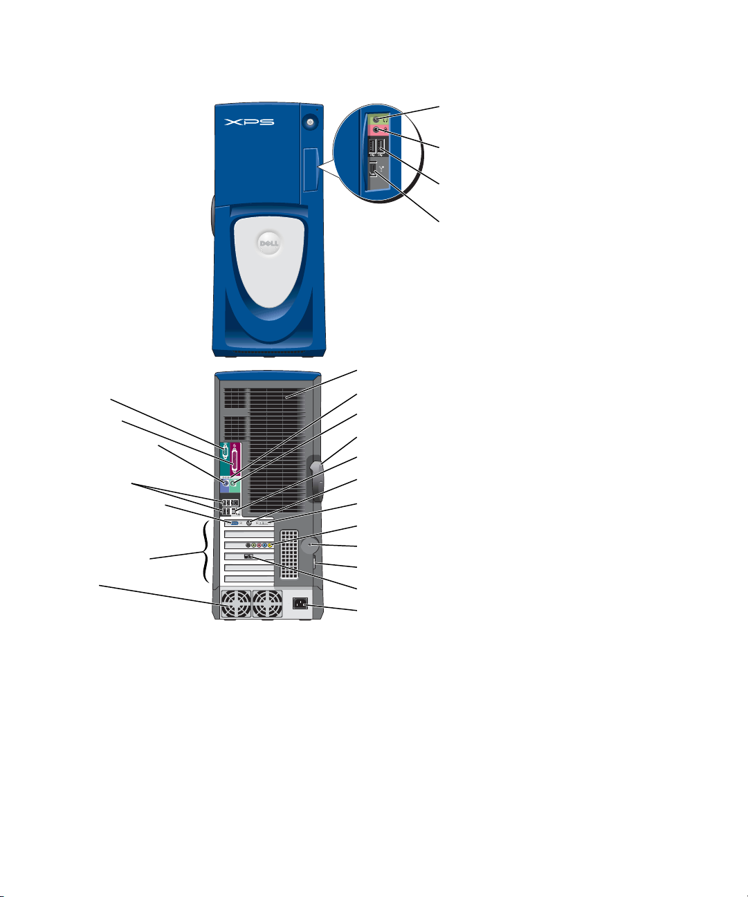
Dell™ Dimension™ XPS Gen 3
serial port
parallel port
keyboard connector
USB 2.0
connectors (6)
VGA video connector
PCI card (4), PCI Express
x1 card (1), PCI Express
x16 card (1) slots
fans (2)
headphone
connector
microphone
connector
USB 2.0
connectors (2)
IEEE 1394
connector
fans (2)
diagnostic lights
mouse connector
cover latch release
network adapter connector
TV-OUT connector
DVI video connector
sound card connectors
security cable slot
padlock ring
modem connector
power connector
Model WHL
www.dell.com | support.dell.com
Page 2

Notes, Notices, and Cautions
NOTE: A NOTE indicates important information that helps you make better use of your computer.
NOTICE: A NOTICE indicates either potential damage to hardware or loss of data and tells you how to avoid the
problem.
CAUTION: A CAUTION indicates a potential for property damage, personal injury, or death.
Abbreviations and Acronyms
For a complete list of abbreviations and acronyms, see the
Dell Dimension Help
file. To access the help file, see
page 10.
If you purchased a Dell™ n Series computer, any references in this document to Microsoft
®
Windows®
operating systems are not applicable.
____________________
Information in this document is subject to change without notice.
© 2004 Dell Inc. All rights reserved.
Reproduction in any manner whatsoever without the written permission of Dell Inc. is strictly forbidden.
Trademarks used in this text: Dell, the DELL logo, Inspiron, Dell Precision, Dimension, OptiPlex, Latitude, PowerEdge, PowerVault, PowerApp,
DellNet, PowerConnect, and Axim are trademarks of Dell Inc.; Intel and Pentium are registered trademarks of Intel Corporation; Microsoft,
Windows, and Outlook are registered trademarks of Microsoft Corporation.
Other trademarks and trade names may be used in this document to refer to either the entities claiming the marks and names or their products.
Dell Inc. disclaims any proprietary interest in trademarks and trade names other than its own.
Model WHL
May 2004 P/N J3186 Rev. A00
www.dell.com | support.dell.com
Page 3

Contents
Finding Information . . . . . . . . . . . . . . . . . . . . . . . . . . . . 9
1 Setting Up and Using Your Computer
Opening the Drive Door . . . . . . . . . . . . . . . . . . . . . . . . . . 13
Changing the Backlight Color
Connecting Two Monitors
Connecting Two Monitors With VGA Connectors
. . . . . . . . . . . . . . . . . . . . . . . 13
. . . . . . . . . . . . . . . . . . . . . . . . . 15
. . . . . . . . . . . . 15
Connecting One Monitor With a VGA connector and One Monitor
With a DVI Connector
Connecting a TV
Changing the Display Settings
About Serial ATA Drives
About Your RAID Configuration
RAID Level 0
RAID Level 1
. . . . . . . . . . . . . . . . . . . . . . . . . . . . . 18
. . . . . . . . . . . . . . . . . . . . . . . . . . . . . 18
Configuring Your Computer for RAID
. . . . . . . . . . . . . . . . . . . . . . . . . 16
. . . . . . . . . . . . . . . . . . . . . . . . . . . 16
. . . . . . . . . . . . . . . . . . . . . 17
. . . . . . . . . . . . . . . . . . . . . . . . . . 17
. . . . . . . . . . . . . . . . . . . . . . . 17
. . . . . . . . . . . . . . . . . . 19
Configuring for RAID Using the Intel(R) Option ROM Utility
Configuring for RAID Using the Intel(R) Application Accelerator
Transferring Information to a New Computer
Copying CDs and DVDs
How to Copy a CD or DVD
. . . . . . . . . . . . . . . . . . . . . . . . . . . 26
. . . . . . . . . . . . . . . . . . . . . . . 26
. . . . . . . . . . . . . . . . 25
Using Blank CD-Rs, CD-RWs, DVD+Rs, and DVD+RWs
Helpful Tips
Network Setup Wizard
. . . . . . . . . . . . . . . . . . . . . . . . . . . . . . 27
. . . . . . . . . . . . . . . . . . . . . . . . . . . 28
. . . . . . . . 20
. . . . . 21
. . . . . . . . . 27
2 Optimizing Performance
Hyper-Threading. . . . . . . . . . . . . . . . . . . . . . . . . . . . . . 29
Overclocking
PCI Express Cards
. . . . . . . . . . . . . . . . . . . . . . . . . . . . . . . 29
. . . . . . . . . . . . . . . . . . . . . . . . . . . . . 30
Contents 3
Page 4

3 Solving Problems
Troubleshooting Tips. . . . . . . . . . . . . . . . . . . . . . . . . . . . 31
Battery Problems
Drive Problems
CD and DVD drive problems
Hard drive problems
E-Mail, Modem, and Internet Problems
Error Messages
IEEE 1394 Device Problems
Keyboard Problems
Lockups and Software Problems
The computer does not start up
The computer stops responding
A program stops responding
A program crashes repeatedly
. . . . . . . . . . . . . . . . . . . . . . . . . . . . . 31
. . . . . . . . . . . . . . . . . . . . . . . . . . . . . . 31
. . . . . . . . . . . . . . . . . . . . . . 32
. . . . . . . . . . . . . . . . . . . . . . . . . . 33
. . . . . . . . . . . . . . . . . . . 33
. . . . . . . . . . . . . . . . . . . . . . . . . . . . . . 34
. . . . . . . . . . . . . . . . . . . . . . . . . 35
. . . . . . . . . . . . . . . . . . . . . . . . . . . . 35
. . . . . . . . . . . . . . . . . . . . . . 36
. . . . . . . . . . . . . . . . . . . . 36
. . . . . . . . . . . . . . . . . . . . 36
. . . . . . . . . . . . . . . . . . . . . . 36
. . . . . . . . . . . . . . . . . . . . . 37
A program is designed for an earlier Windows operating system
A solid blue screen appears
Other software problems
Memory Problems
Mouse Problems
. . . . . . . . . . . . . . . . . . . . . . . . . . . . . 38
. . . . . . . . . . . . . . . . . . . . . . . . . . . . . . 38
. . . . . . . . . . . . . . . . . . . . . . 37
. . . . . . . . . . . . . . . . . . . . . . . 37
. . . . . 37
4 Contents
Network Problems
Power Problems
Printer Problems
Scanner Problems
. . . . . . . . . . . . . . . . . . . . . . . . . . . . . 39
. . . . . . . . . . . . . . . . . . . . . . . . . . . . . . 40
. . . . . . . . . . . . . . . . . . . . . . . . . . . . . . 41
. . . . . . . . . . . . . . . . . . . . . . . . . . . . . 41
Sound and Speaker Problems
No sound from speakers
No sound from headphones
Video and Monitor Problems
If the screen is blank
. . . . . . . . . . . . . . . . . . . . . . . . . 44
If the screen is difficult to read
. . . . . . . . . . . . . . . . . . . . . . . 42
. . . . . . . . . . . . . . . . . . . . . . . . 42
. . . . . . . . . . . . . . . . . . . . . . 43
. . . . . . . . . . . . . . . . . . . . . . . . 44
. . . . . . . . . . . . . . . . . . . . . 44
Page 5

4 Advanced Troubleshooting
Diagnostic Lights . . . . . . . . . . . . . . . . . . . . . . . . . . . . . 47
Dell Diagnostics
When to Use the Dell Diagnostics
Drivers
. . . . . . . . . . . . . . . . . . . . . . . . . . . . . . . . . . 53
What Is a Driver?
Identifying Drivers
Reinstalling Drivers
Using Microsoft
Creating a Restore Point
Restoring the Computer to an Earlier Operating State
Undoing the Last System Restore
Resolving Software and Hardware Incompatibilities
Reinstalling Microsoft
Before You Begin
Reinstalling Windows XP
. . . . . . . . . . . . . . . . . . . . . . . . . . . . . . 50
. . . . . . . . . . . . . . . . . . . 50
. . . . . . . . . . . . . . . . . . . . . . . . . . . 53
. . . . . . . . . . . . . . . . . . . . . . . . . . . 53
. . . . . . . . . . . . . . . . . . . . . . . . . . 54
®
Windows® XP System Restore . . . . . . . . . . . . . . 55
. . . . . . . . . . . . . . . . . . . . . . . . 56
. . . . . . . . . . 56
. . . . . . . . . . . . . . . . . . . 56
. . . . . . . . . . . . 57
®
Windows® XP. . . . . . . . . . . . . . . . . . . 57
. . . . . . . . . . . . . . . . . . . . . . . . . . . 57
. . . . . . . . . . . . . . . . . . . . . . . 58
5 Removing and Installing Parts
Before You Begin . . . . . . . . . . . . . . . . . . . . . . . . . . . . . 61
Recommended Tools
Turning Off Your Computer
Before Working Inside Your Computer
. . . . . . . . . . . . . . . . . . . . . . . . . 61
. . . . . . . . . . . . . . . . . . . . . . . 61
. . . . . . . . . . . . . . . . . 62
Front and Back View of the Computer
Front View
Front View (Doors Open)
Back View
Opening the Computer Cover
Inside View of Your Computer
System Board Components
Memory
Installing Memory
Removing Memory
. . . . . . . . . . . . . . . . . . . . . . . . . . . . . . 63
. . . . . . . . . . . . . . . . . . . . . . . . 64
. . . . . . . . . . . . . . . . . . . . . . . . . . . . . . 65
. . . . . . . . . . . . . . . . . . . . . . . . 67
. . . . . . . . . . . . . . . . . . . . . . . 68
. . . . . . . . . . . . . . . . . . . . . . . . . 69
. . . . . . . . . . . . . . . . . . . . . . . . . . . . . . . . . . 70
. . . . . . . . . . . . . . . . . . . . . . . . . . . 71
. . . . . . . . . . . . . . . . . . . . . . . . . . 73
. . . . . . . . . . . . . . . . . . . . 63
Contents 5
Page 6

Cards . . . . . . . . . . . . . . . . . . . . . . . . . . . . . . . . . . . 73
PCI Cards
PCI Express Cards
Drives
General Installation Guidelines
Connecting Drive Cables
. . . . . . . . . . . . . . . . . . . . . . . . . . . . . . . 74
. . . . . . . . . . . . . . . . . . . . . . . . . . . 77
. . . . . . . . . . . . . . . . . . . . . . . . . . . . . . . . . . . 82
. . . . . . . . . . . . . . . . . . . . . 82
. . . . . . . . . . . . . . . . . . . . . . . 83
Hard Drive
. . . . . . . . . . . . . . . . . . . . . . . . . . . . . . . . . 84
Removing a Hard Drive
Installing a Hard Drive
. . . . . . . . . . . . . . . . . . . . . . . . 84
. . . . . . . . . . . . . . . . . . . . . . . . . 85
Adding a Second Hard Drive
Floppy Drive
CD/DVD Drive
Processor Airflow Shroud
. . . . . . . . . . . . . . . . . . . . . . . . . . . . . . . . 89
Removing a Floppy Drive
Installing a Floppy Drive
. . . . . . . . . . . . . . . . . . . . . . . . . . . . . . . 92
Removing a CD/DVD Drive
Installing a CD/DVD Drive
. . . . . . . . . . . . . . . . . . . . . . . 89
. . . . . . . . . . . . . . . . . . . . . . . . 90
. . . . . . . . . . . . . . . . . . . . . . . 92
. . . . . . . . . . . . . . . . . . . . . . . 93
. . . . . . . . . . . . . . . . . . . . . . . . . 96
Removing the Processor Airflow Shroud
Installing the Processor Airflow Shroud
Processor
Front Panel
Drive Door
. . . . . . . . . . . . . . . . . . . . . . . . . . . . . . . . . 97
Removing the Processor
Installing the Processor
. . . . . . . . . . . . . . . . . . . . . . . . . . . . . . . 102
Removing the Front Panel
Replacing the Front Panel
. . . . . . . . . . . . . . . . . . . . . . . . . . . . . . . . 104
Removing the Drive Door
Replacing the Drive Door
. . . . . . . . . . . . . . . . . . . . . . . . 97
. . . . . . . . . . . . . . . . . . . . . . . 100
. . . . . . . . . . . . . . . . . . . . . . 102
. . . . . . . . . . . . . . . . . . . . . . 103
. . . . . . . . . . . . . . . . . . . . . . 104
. . . . . . . . . . . . . . . . . . . . . . 105
. . . . . . . . . . . . . . . . . . . . . . 88
. . . . . . . . . . . . . . . . 96
. . . . . . . . . . . . . . . . 97
6 Contents
Battery
. . . . . . . . . . . . . . . . . . . . . . . . . . . . . . . . . 107
Replacing the Battery
Closing the Computer Cover
. . . . . . . . . . . . . . . . . . . . . . . . 107
. . . . . . . . . . . . . . . . . . . . . . . 108
Page 7

6 Appendix
Specifications . . . . . . . . . . . . . . . . . . . . . . . . . . . . . . 109
System Setup
Overview
Entering System Setup
System Setup Options
Boot Sequence
Clearing Forgotten Passwords
Clearing CMOS Settings
Dell Technical Support Policy (U.S. Only)
Definition of "Dell-Installed" Software and Peripherals
Definition of "Third-Party" Software and Peripherals
Contacting Dell
. . . . . . . . . . . . . . . . . . . . . . . . . . . . . . 113
. . . . . . . . . . . . . . . . . . . . . . . . . . . . . . 113
. . . . . . . . . . . . . . . . . . . . . . . . 114
. . . . . . . . . . . . . . . . . . . . . . . . 115
. . . . . . . . . . . . . . . . . . . . . . . . . . . 118
. . . . . . . . . . . . . . . . . . . . . . 119
. . . . . . . . . . . . . . . . . . . . . . . . . 120
. . . . . . . . . . . . . . . . . 121
. . . . . . . . 121
. . . . . . . . . 121
. . . . . . . . . . . . . . . . . . . . . . . . . . . . . 121
Index . . . . . . . . . . . . . . . . . . . . . . . . . . . . . . . . . . . 139
Contents 7
Page 8

8 Contents
Page 9
Finding Information
What Are You Looking For? Find it Here
• How to access tutorials and other how to information
• How to get a copy of my invoice
• How to extend my warranty
• How to access Dell Support on my Microsoft
Windows
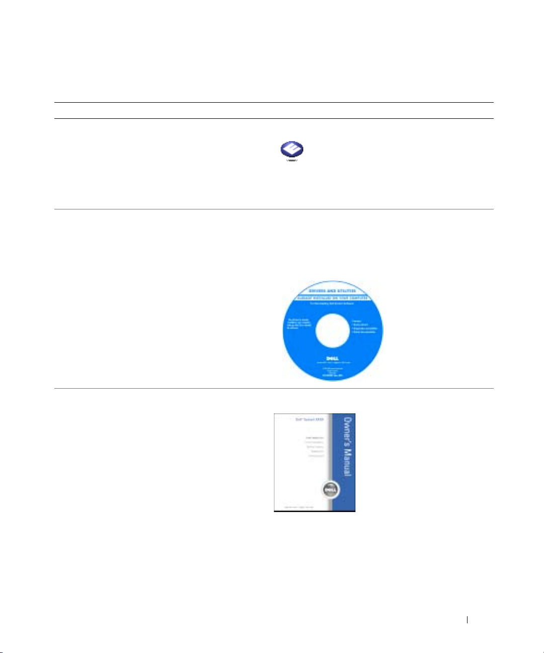
• Additional documentation, tools, troubleshooting
information, and links to online support resources
• A diagnostic program for my computer
• Drivers for my computer
• My computer documentation
• My device documentation
®
desktop (U.S. only)
®
Dell Solution Center
ResourceCD
Documentation and drivers are already installed on your
computer. You can use the CD to reinstall drivers (see
page 54), run the Dell Diagnostics (see page 50), or
access your documentation.
On your Windows desktop
Readme files may be
included on your CD to
provide last-minute
updates about technical
changes to your
computer or advanced
technical-reference
material for technicians
or experienced users.
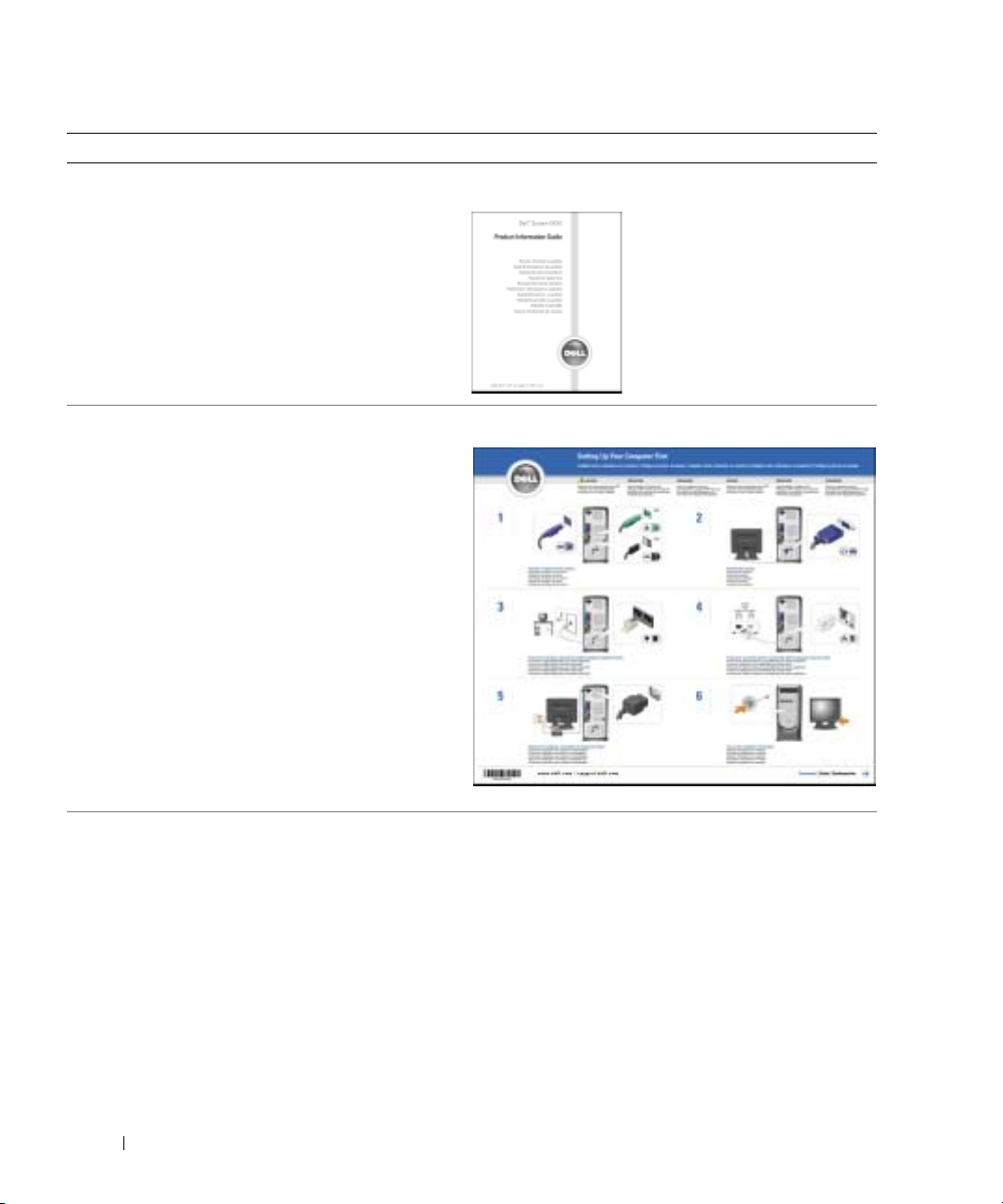
• Additional information about setting up my computer
• How to troubleshoot and solve problems
• How to remove and install parts
• Technical specifications
• How to contact Dell
Dimension Owner’s Manual
NOTE: This document is available as a PDF at
support.dell.com.
Finding Information 9
Page 10
What Are You Looking For? Find it Here
• Warranty information
Dell™ Product Information Guide
• Safety instructions
• Regulatory information
• Ergonomics information
• End User License Agreement
www.dell.com | support.dell.com
• How to set up my computer
Setup Diagram
• Tips on using Microsoft® Windows
®
• How to play CDs and DVDs
• How to use standby mode and hibernate mode
• How to change my display resolution
• How to clean my computer
10 Finding Information
The Dell Dimension Help file
1
Click the
2
Click
3
Click
Start
button and click
User and system guides
Dell Dimension Help
Help and Support
and click
User’s guides
.
.
.
Page 11

What Are You Looking For? Find it Here
• Service Tag and Express Service Code
• Microsoft Windows License Label
Service Tag and Microsoft Windows License
These labels are located on your computer.
• Enter the Express Service Code to direct your call when
contacting technical support. The Express Service Code
is not available in all countries.
• Latest drivers for my computer
• Answers to technical service and support questions
• Online discussions with other users and technical
support
• Documentation for my computer
Dell Support Website — support.dell.com
NOTE: Select your region to view the appropriate support
site.
The Dell Support website provides several online tools,
including:
• Solutions — Troubleshooting hints and tips, articles
from technicians, and online courses
• Community — Online discussion with other Dell
customers
• Upgrades — Upgrade information for components, such
as memory, the hard drive, and the operating system
• Customer Care — Contact information, order status,
warranty, and repair information
• Downloads — Drivers, patches, and software updates
• Reference — Computer documentation, product
specifications, and white papers
• How to use Windows XP
• Documentation for my computer
• Documentation for devices (such as a modem)
Windows Help and Support Center
1
Click the
2
Type a word or phrase that describes your problem and
click the arrow icon.
3
Click the topic that describes your problem.
4
Follow the instructions on the screen.
Start
button and click
•Use the Service Tag to
identify your computer
when you use
support.dell.com
or
contact technical
support.
Help and Support
.
Finding Information 11
Page 12

What Are You Looking For? Find it Here
• How to reinstall my operating system
Operating System CD
The operating system is already installed on your
computer. To reinstall your operating system, use the
Operating System CD. See "Reinstalling Microsoft
Windows
www.dell.com | support.dell.com
®
XP" on page 57.
®
After you reinstall your
operating system, use the
ResourceCD to reinstall
drivers for the devices
that came with your
computer.
NOTE: The color of your
CD varies based on the
operating system you
ordered.
12 Finding Information
Page 13
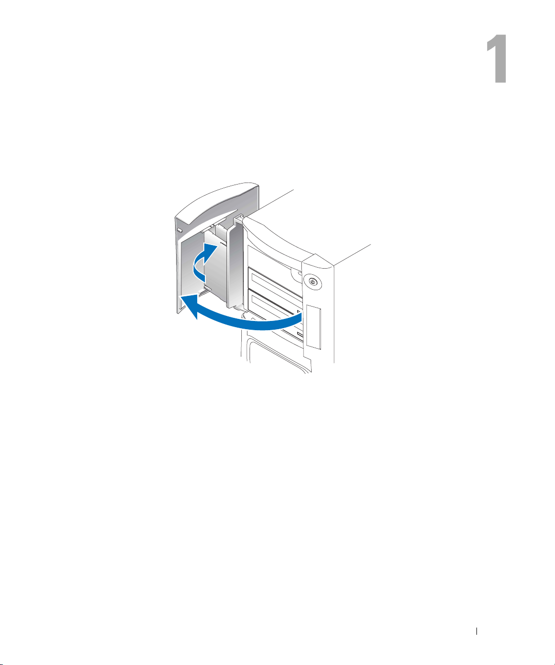
Setting Up and Using Your Computer
Opening the Drive Door
Changing the Backlight Color
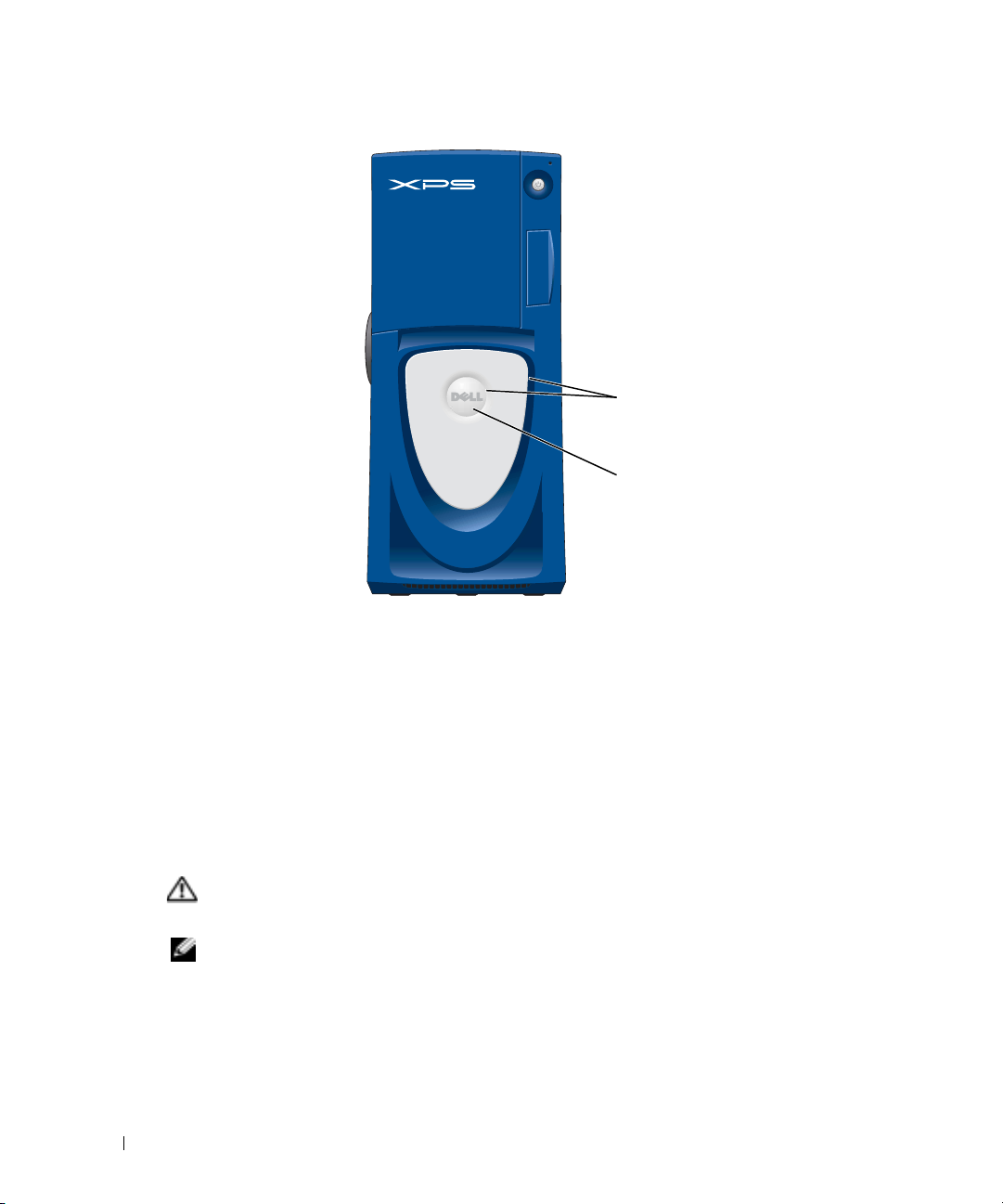
You can use this exclusive Dell™ Dimension™ XPS Gen 3 feature either to change the color of the
backlight that illuminates the Dell name and displays around the badge on the front of your
computer, or to turn off the backlight entirely.
Setting Up and Using Your Computer 13
Page 14
www.dell.com | support.dell.com
There are several color choices:
• Ruby
•Emerald
• Sapphire (default)
•Amber
• Amethyst
•Topaz
• Diamond
CAUTION: Before you begin any of the procedures in this section, follow the safety instructions
located in the Product Information Guide.
backlight
badge
NOTE: The backlight is not for diagnostic purposes.
Follow the procedures in "Before You Begin" on page 61.
1
2
Turn on (or restart) your computer.
3
Enter system setup (see page 114).
4
Scroll through the color options using the up- and down-arrow keys, select
press <Enter>.
14 Setting Up and Using Your Computer
System
, and then
Page 15

5
Click
Front LED Color
6
Press the left- and right- arrow keys to scroll through the color options. The backlight color
, and press <Enter>.
changes as you scroll through the options.
7
Select the color you want, and press <Enter>.
8
Press <Esc>, and press
Save and Exit
to save the new backlight color setting.
Connecting Two Monitors
CAUTION: Before you begin any of the procedures in this section, follow the safety instructions
located in the Product Information Guide.
NOTE: If you are connecting two monitors that have VGA connectors, you must have the optional DVI
adapter. If you are connecting two flat-panel monitors, at least one of them must have a VGA connector.
If you are connecting a TV, you may connect only one monitor (VGA or DVI) in addition to the TV.
NOTE: See the documentation that came with your TV to ensure that you properly configure and connect
the TV.
If you purchased a graphics card that supports dual monitors, follow these instructions to connect
and enable your monitors. The instructions tell you how to connect either two monitors (each with
a VGA connector), one monitor with a VGA connector and one monitor with a DVI connector, or
aTV.
Connecting Two Monitors With VGA Connectors
1
Follow the procedures in "Before You Begin" on page 61.
NOTE: If your computer has integrated video, do not connect either monitor to the integrated video
connector. If the integrated video connector is covered by a cap, do not remove the cap to connect the
monitor or the monitor will not function.
2
Connect one of the monitors to the VGA (blue) connector on the back of the computer.
3
Connect the other monitor to the optional DVI adapter and connect the DVI adapter to the
DVI (white) connector on the back of the computer.
Setting Up and Using Your Computer 15
Page 16
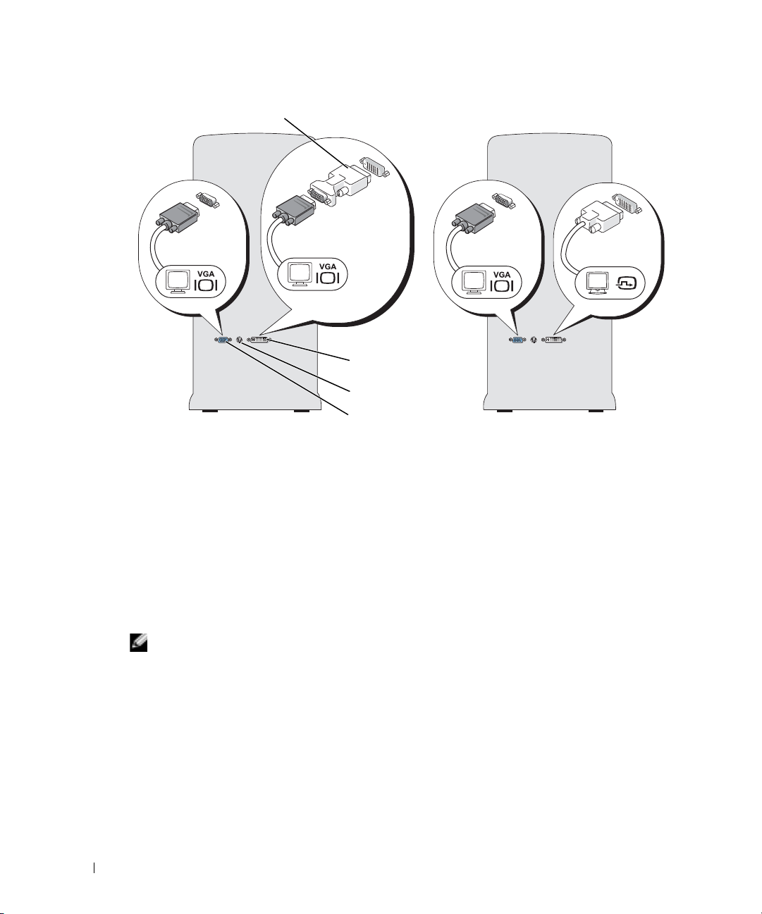
optional DVI adapter
www.dell.com | support.dell.com
Connecting One Monitor With a VGA connector and One Monitor With a DVI Connector
1
Follow the procedures in "Before You Begin" on page 61.
2
Connect the VGA connector on the monitor to the VGA (blue) connector on the back of the
computer.
3
Connect the DVI connector on the other monitor to the DVI (white) connector on the back
of the computer.
DVI (white) connector
TV-OUT connector
VGA (blue) connector
Connecting a TV
NOTE: To connect a TV to your computer, you must purchase an S-video cable, which is available at
most consumer electronics stores. An S-video cable is not included with your computer.
Follow the procedures in "Before You Begin" on page 61.
1
2
Connect one end of the S-video cable to the TV-OUT connector on the back of the computer.
3
Connect the other end of the S-video cable to the S-video input connector on your TV.
4
Connect the VGA or DVI monitor as described above on page 16.
16 Setting Up and Using Your Computer
Page 17

Changing the Display Settings
1
After you connect the monitor(s) or TV, turn on the computer.
®
The Microsoft
2
Enable clone mode or extended desktop mode in the display settings.
• In clone mode, both monitors display the same image.
• In extended desktop mode, you can drag objects from one screen to the other, effectively
doubling the amount of viewable work space.
For information on changing the display settings for your graphics card, see the user’s guide in
the Help and Support Center (click the
system guides
Windows® desktop displays on the primary monitor.
Start
, click
Device guides
button, click
, and then click the guide for your graphics card).
Help and Support
, click
User and
About Serial ATA Drives
Your Dell™ Dimension™ XPS computer supports up to three serial ATA hard drives. Serial ATA
drives provide the following benefits by transferring data using serial technology and flexible cables
that are thinner and longer than IDE cables:
• Improved cable routing facilitates more efficient airflow inside the chassis.
• Compact cable connectors save space on the system board and on the hard drive. Combined
with the improved cable routing, this allows a more efficient utilization of space inside the
chassis.
See "Hard Drive" on page 84 for information on serial ATA drive connections.
About Your RAID Configuration
This section provides an overview of the RAID configuration that you might have selected when
you purchased your computer. Although several RAID configurations are available, Dell offers
either RAID level 0 or RAID level 1 for its Dimension computers. A RAID level 0 configuration is
recommended for high-performance gaming, and a RAID level 1 configuration is recommended for
the data integrity requirements of digital photography and audio.
The Intel RAID controller on your computer can only create a RAID volume using two physical
drives. If a third drive is present, then that drive cannot be made part of a RAID volume using the
Intel RAID configuration program, although it can be used as a spare drive in a RAID 1
configuration (see "Creating a Spare Hard Drive" on page 24). However, if four drives are present in
your computer, then each pair of drives can be made into RAID level 0 or RAID level 1 volumes.
The drives should be the same size in order to ensure that the larger drive does not contain
unallocated (and therefore unusable) space.
NOTE: RAID levels do not represent a hierarchy. A RAID level 1 configuration is not inherently better or
worse than a RAID level 0 configuration.
Setting Up and Using Your Computer 17
Page 18
RAID Level 0
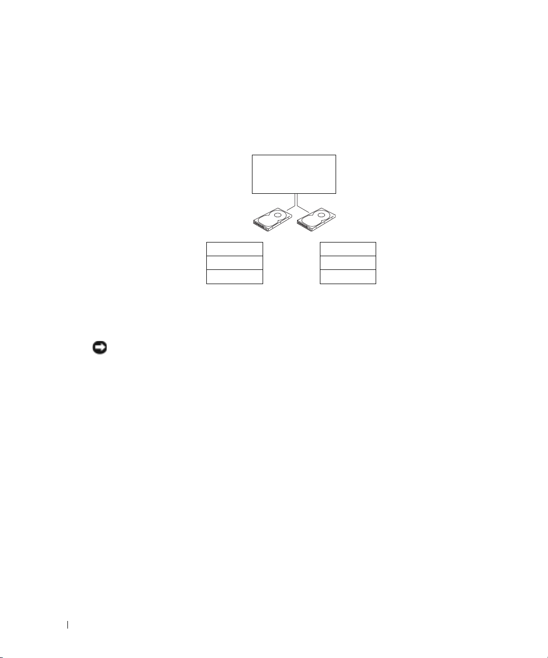
RAID level 0 uses a storage technique known as "data striping" to provide a high data access rate.
Data striping is a method of writing consecutive segments, or stripes, of data sequentially across
the physical drives to create a large virtual drive. Data striping allows one of the drives to read data
while the other drive is searching for and reading the next block.
www.dell.com | support.dell.com
serial ATA RAID
configured for
RAID level 0
segment 1
segment 3
segment 5
hard drive 1
segment 2
segment 4
segment 6
hard drive 2
Another advantage of a RAID level 0 configuration is that it utilizes the full capacities of the drives.
For example, if you have two 120-GB drives installed, you have 240 GB on which to store data.
NOTICE: Because RAID level 0 provides no data redundancy, if one drive fails, then the data on the other
drive is also inaccessible. Therefore, ensure that you perform regular backups when you use a RAID
level 0 configuration.
RAID Level 1
RAID level 1 uses a data-redundancy storage technique known as "mirroring." When data is written
to the primary drive, it is then duplicated, or mirrored, on the other drive. A RAID level 1
configuration sacrifices high data access rates for its data redundancy advantages.
18 Setting Up and Using Your Computer
Page 19
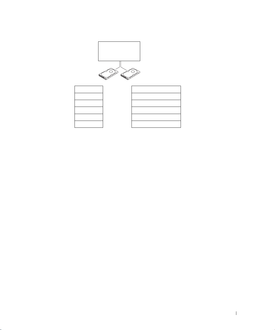
serial ATA RAID
configured for
RAID level 1
segment 1
segment 2
segment 3
segment 4
segment 5
segment 6
hard drive 1
segment 1 duplicated
segment 2 duplicated
segment 3 duplicated
segment 4 duplicated
segment 5 duplicated
segment 6 duplicated
hard drive 2
If a drive failure occurs, subsequent read and write operations are directed to the surviving drive. A
replacement drive can then be rebuilt using the data from the surviving drive. Also, because data is
duplicated on both drives, two 120-GB RAID level 1 drives collectively have a maximum of 120-GB
on which to store data.
Configuring Your Computer for RAID
At some point you may want to configure your computer for RAID if you did not select a RAID
configuration when you purchased your computer. You must have at least two hard drives installed
in your computer to set up a RAID configuration. For instructions on how to install a hard drive,
see page 85.
You can use one of two methods to configure RAID hard drive volumes. One method uses the
Intel(R) Option ROM utility, and is performed
hard drive. The second method uses the Intel Application Accelerator, or Intel Storage Utility, and
this method is performed
after
you have installed the operating system and the Intel Storage
Utility. Both methods require that you set your computer to RAID-enabled mode before starting
any of the RAID configuration procedures in this document.
before
you install the operating system onto the
Setting Your Computer to RAID-Enabled Mode
1
Enter system setup (see page 114).
2
Use the up- and down-arrow keys to highlight
3
Use the up- and down-arrow keys to highlight
4
Use the left- and right-arrow keys to highlight
<Esc>.
Drives
, and press <Enter>.
Drive Controller
RAID On
, press <Enter>, and then press
Setting Up and Using Your Computer 19
, and press <Enter>.
Page 20

5
Use the left- and right-arrow keys to highlight
setup and resume the boot process.
Configuring for RAID Using the Intel(R) Option ROM Utility
NOTE: Although any size drives may be used to create a RAID configuration using the Intel Option ROM
utility, ideally the drives should be of equal size. In a RAID level 0 configuration, the size of the array will
be the size of the smallest disk multiplied by the number (two) of disks in the array. In a RAID level 1
configuration, the size of the array will be the smaller of the two disks used.
Creating a RAID Level 0 Configuration
NOTICE: You will lose any data on your hard drives when you create a RAID configuration using the
www.dell.com | support.dell.com
following procedure. Back up data you want to keep before continuing.
NOTE: The following procedure should only be used if you are reinstalling your operating system. The
following procedure should not be used to migrate an existing storage configuration to RAID 0.
1
Set your computer to RAID-enabled mode (see page 19).
2
Press <Ctrl><i> when you are prompted to enter the Intel(R) RAID Option ROM utility.
3
Use the up- and down-arrow keys to highlight
4
Enter a RAID volume name or accept the default, and press <Enter>.
5
Use the up- and down-arrow keys to select
6
If there are more than two hard disks available, use the up- and down-arrow keys and space bar
to select the two disks you want to use to make up your array, and then press <Enter>.
Save/Exit
, and press <Enter> to exit system
Create RAID Volume
RAID0(Stripe)
, and press <Enter>.
, and press <Enter>.
NOTE: Select the strip size closest to the size of the average file you want to store on the RAID volume. If
you do not know the average file size, choose 128 as your strip size.
Use the up- and down-arrow keys to change the strip size, and press <Enter>.
7
8
Select the desired capacity for the volume, and press <Enter>. The default value is the
maximum available size.
9
Press <Enter> to create the volume.
10
Press <y> to confirm that you want to create the RAID volume.
11
Confirm that the correct volume configuration is displayed on the main Intel Option ROM
screen.
12
Use the up- and down-arrow keys to select
13
Install the operating system (see "Reinstalling Microsoft® Windows® XP" on page 57).
Creating a RAID Level 1 Configuration
1
Set your computer to RAID-enabled mode (see page 19).
2
Press <Ctrl><i> when you are prompted to enter Intel RAID Option ROM.
3
Use the up- and down-arrow keys to highlight
20 Setting Up and Using Your Computer
Exit
, and press <Enter>.
Create RAID Volume
, and press <Enter>.
Page 21

4
Enter a RAID volume name or accept the default, and press <Enter>.
5
Use the up- and down-arrow keys to select
6
If there are more than two hard disks available, use the up- and down-arrow keys and space bar
RAID1(Mirror)
, and press <Enter>.
to select the two disks you want to use to make up your array, and then press <Enter>.
7
Select the desired capacity for the volume, and press <Enter>. The default value is the
maximum available size.
8
Press <Enter> to create the volume.
9
Press <y> to confirm that you want to create the RAID volume.
10
Confirm that the correct volume configuration is displayed on the main Intel Option ROM
screen.
11
Use the up- and down-arrow keys to select
12
Install the operating system (see "Reinstalling Microsoft® Windows® XP" on page 57).
Deleting a RAID Volume
NOTE: When you perform this operation, all data on the RAID drives will be lost.
NOTE: If your computer currently boots to RAID and you delete the RAID volume in the Intel RAID Option
ROM, your computer will become unbootable.
Press <Ctrl><i> when you are prompted to enter the Intel RAID Option ROM utility.
1
2
Use the up- and down-arrow keys to highlight
3
Use the up- and down-arrow keys to highlight the RAID volume you want to delete, and press
Exit
, and press <Enter>.
Delete RAID Volume
, and press <Enter>.
<Delete>.
4
Press <y> to confirm the deletion of the RAID volume.
5
Press <Esc> to exit the Intel Option ROM utility.
Configuring for RAID Using the Intel(R) Application Accelerator
If you already have one hard drive with the operating system installed on it, and you want to add a
second hard drive and reconfigure both drives into a RAID volume without losing the existing
operating system and any data, you need to use the migrating option (see "Migrating to a RAID 0
Volume" on page 23 or "Migrating to a RAID 1 Volume" on page 24). Create a RAID 0 Volume or
RAID 1 Volume only when:
• You are adding two new drives to an existing single-drive computer (and the operating system
is on the single drive), and you want to configure the two new drives into a RAID volume.
• You already have a two-hard drive computer configured into an array, but you still have some
space left on the array that you want to designate as a second RAID volume.
Setting Up and Using Your Computer 21
Page 22

Creating a RAID 0 Volume
NOTE: When you perform this operation, all data on the RAID drives will be lost.
Set your computer to RAID-enabled mode (see page 19).
1
2
Click
Start
Accelerator
NOTE: If you do not see an Actions menu option, you have not yet set your computer to RAID-enabled
mode (see page 19).
On the
3
Wizard, and then click
4
www.dell.com | support.dell.com
On the
RAID 0 volume, and then click the right arrow. Click a second hard drive until two drives
appear in the
5
In the
Specify Volume Size
6
Click
Finish
Creating a RAID 1 Volume
NOTE: When you perform this operation, all data on the RAID drives will be lost.
Set your computer to RAID-enabled mode (see page 19).
1
2
Click the
Application Accelerator
and point to
Programs→ Intel(R) Application Accelerator→ Intel Application
to launch the Intel(R) Storage Utility.
Actions
Select Volume Location
menu, select
Next
Selected
window, and then click
Create RAID Volume
.
screen, click the first hard drive you want to include in your
window, click the
to create the volume, or click
Start
button and point to
Programs→ Intel(R) Application Accelerator→ Intel
to launch the Intel(R) Storage Utility.
to launch the Create RAID Volume
Next
.
Volume Size
Back
to make changes.
desired, and then click
Next
.
NOTE: If you do not see an Actions menu option, you have not yet set your computer to RAID-enabled
mode (see page 19).
3
On the
Actions
menu, select
Wizard.
4
Click
Next
at the first screen.
5
Confirm the volume name, select
6
On the
Select Volume Location
your RAID 0 volume, and then click the right arrow. Click a second hard drive until two drives
appear in the
7
In the
8
Click
Finish
9
Follow Microsoft Windows procedures for creating a partition on the new RAID volume.
Selected
Specify Volume Size
to create the volume, or click
22 Setting Up and Using Your Computer
Create RAID Volume
RAID 1
as the RAID level, and then click
screen, click the first hard drive you want to use to create
window, and then click
window, select the
Back
to launch the Create RAID Volume
Next
Next
.
Volume Size
desired and click
to make changes.
to continue.
Next
.
Page 23

Deleting a RAID Volume
NOTE: While this procedure deletes the RAID 1 volume, it also splits the RAID 1 volume into two non-
RAID hard drives with a partition, and leaves any existing data files intact. Deleting a RAID 0 volume,
however, destroys all data on the volume.
Click the
1
Application Accelerator
2
Right-click the
Volum e
3
On the
4
Highlight the RAID volume you want to delete in the
button to move the highlighted RAID volume into the
5
Click
Migrating to a RAID 0 Volume
1
Set your computer to RAID-enabled mode (see page 19).
2
Click the
Application Accelerator
NOTE: If you do not see an Actions menu option, you have not yet set your computer to RAID-enabled
mode (see page 19).
On the
3
Start
button and point to
to launch the Intel(R) Storage Utility.
Volu me
icon of the RAID volume you want to delete, and select
.
Delete RAID Volume Wizard
Finish
to delete the volume.
Start
button and point to
to launch the Intel(R) Storage Utility.
Actions
menu, select
Create RAID Volume From Existing Hard Drive to
Programs→ Intel(R) Application Accelerator→ Intel
Delete
screen, click
Next
Available
Selected
.
box, click the right-arrow
box, and then click
All Programs→ Intel(R) Application Accelerator→ Intel
Migration Wizard.
4
Click
Next
on the Migration Wizard screen.
5
Enter a RAID volume name or accept the default.
6
From the drop-down box, select
RAID 0
as the RAID level
.
Next
.
launch the
NOTE: Select the strip size closest to the size of the average file you want to store on the RAID volume. If
you do not know the average file size, choose 128 as your strip size.
Select the appropriate strip size from the drop-down box, and then click
7
NOTE: Select the hard drive that you want to use as your source hard drive (it should be the hard drive
containing the data or operating system files that you want to keep on the RAID volume).
8
On the
migrate, and click
9
On the
drive to span the stripe array, and click
10
On the
NOTE: In the following step, you will lose all data contained on the member drive.
Select Source Hard Drive
Next
.
screen, double-click the hard drive from which you want to
Select Member Hard Drive
Specify Volume Size
screen, select the
screen, double-click the hard drive to select the member
Next
.
Volume Size
you want, and click
Setting Up and Using Your Computer 23
Next
.
Next
.
Page 24

11
Click
Finish
normally during the migration process.
Migrating to a RAID 1 Volume
1
Set your computer to RAID-enabled mode (see page 19).
2
Click the
Application Accelerator
NOTE: If you do not see an Actions menu option, you have not yet set your computer to RAID-enabled
mode (see page 19).
On the
3
www.dell.com | support.dell.com
Migration Wizard.
4
Click
Next
5
Enter a RAID volume name or accept the default.
6
From the drop-down box, select
NOTE: Select the hard drive that you want to use as your source hard drive (it should be the hard drive
containing the data or operating system files that you want to keep on the RAID volume).
On the
7
migrate, and click
8
On the
drive that you want to act as the mirror in the array, and click
9
On the
to start migrating, or click
Start
button and point to
Back
All Programs→ Intel(R) Application Accelerator→ Intel
to launch the Intel(R) Storage Utility.
Actions
menu, click
Create RAID Volume From Existing Hard Drive
on the first Migration Wizard screen.
RAID 1
Select Source Hard Drive
Next
.
Select Member Hard Drive
Specify Volume Size
screen, double-click the hard drive from which you want to
screen, double-click the hard drive to select the member
screen, select the volume size you want, and click
to make changes. You can use your computer
to launch the
as the RAID level
.
Next
.
Next
.
NOTE: In the following step, you will lose all data contained on the member drive.
Click
Finish
10
to start migrating, or click
normally during migration process.
Creating a Spare Hard Drive
A spare hard drive may be created with a RAID 1 array. The spare hard drive will not be recognized
by the operating system, but you will be able to see the spare drive from within Disk Manager or the
Intel Option ROM Utility. When a member of the RAID 1 array is broken, the computer
automatically rebuilds the mirror array using the spare hard drive as the broken member’s
replacement.
To Mark a Drive as a Spare Hard Drive:
1
Click the
Start
button and point to
Application Accelerator
2
Right-click the hard drive you want to mark as a spare hard drive.
3
Click
Mark as Spare
.
24 Setting Up and Using Your Computer
Back
to make changes. You can use your computer
Programs→ Intel(R) Application Accelerator→ Intel
to launch the Intel(R) Storage Utility.
Page 25

To Remove Spare Marking From a Spare Hard Drive:
1
Right-click the spare hard drive icon.
2
Click
Reset Hard Drive to Non-RAID
Rebuilding a Degraded RAID 1 Volume
If your computer does not have a spare hard drive, and the computer has reported a degraded RAID
1 volume, you can manually rebuild the computer’s redundancy mirror to a new hard drive by
performing the following steps:
1
Click the
Application Accelerator
2
Right-click the available hard drive to which you want to rebuild the RAID 1 volume, and
click
3
You can use your computer while the computer is rebuilding the RAID 1 volume.
Start
button and point to
to launch the Intel(R) Storage Utility.
Rebuild to this Disk
Programs→ Intel(R) Application Accelerator→ Intel
.
Transferring Information to a New Computer
The Microsoft® Windows® XP operating system provides a Files and Settings Transfer wizard to
move data from the source computer to the new computer. You can move data such as:
•E-mails
• Toolbar settings
• Window sizes
• Internet bookmarks
You can transfer the data to the new computer over a network or serial connection, or you can store
it on a removable medium, such as a writable CD or floppy disk.
To prepare the new computer for the file transfer:
1
Click the
Files and Settings Transfer Wizard
2
When the
3
On the
4
On the
Windows XP CD
5
When the
Do not
To copy data from the old computer:
1
On the old computer, insert the Windows XP
2
On the
Start
button, point to
All Programs→ Accessories→ System Tools
.
Files and Settings Transfer Wizard
Which computer is this?
Do you have a Windows XP CD?
and click
Now go to your old computer
click
Next
at this time.
screen, click
Next
.
screen, click
screen appears, go to your old or source computer.
Welcome to Microsoft Windows XP
welcome screen appears, click
New Computer
and click
I will use the wizard from the
Operating System
screen, click
CD.
Perform additional tasks
, and then click
Next
.
Next
.
.
Setting Up and Using Your Computer 25
Page 26

3
Under
What do you want to do?
4
On the
5
On the
6
On the
7
On the
Next
.
After the information has been copied, the
8
Click
Finish
To transfer data to the new computer:
www.dell.com | support.dell.com
1
2
On the
On the
your settings and files and click
The wizard reads the collected files and settings and applies them to your new computer.
, click
Transfer files and settings
Files and Settings Transfer Wizard
Which computer is this?
Select a transfer method
What do you want to transfer?
screen, click
screen, click the transfer method you prefer.
screen, select the items you want to transfer and click
.
Now go to your old computer
screen on the new computer, click
Where are the files and settings?
Next
.
.
welcome screen, click
Old Computer
Completing the Collection Phase
Next
and click
.
Next
.
Next
screen appears.
.
screen, select the method you chose for transferring
When all of the settings and files have been applied, the
3
Click
Finished
and restart the new computer.
Finished
screen appears.
Copying CDs and DVDs
NOTE: Ensure that you follow all copyright laws when you create CDs or DVDs.
This section applies only to computers that have a CD-R, CD-RW, DVD+RW, DVD+R, or
DVD/CD-RW combo drive.
NOTE: The types of CD or DVD drives offered by Dell may vary by country.
The following instructions show how to make an exact copy of a CD or DVD. You can also use
Sonic RecordNow for other purposes, including creating CDs from audio files on your computer
and creating MP3 CDs. For instructions, see the Sonic RecordNow documentation that came with
your computer. Open Sonic RecordNow, click the question mark icon in the upper-right corner of
the window, and then click
How to Copy a CD or DVD
NOTE: If you have a DVD/CD-RW combo drive and you experience recording problems, check for
available software patches at the Sonic support website at support.sonic.com.
Currently, five DVD-writable disc formats available: DVD+R, DVD+RW, DVD-R, DVD-RW and
DVD-RAM. The DVD-writable drives installed in Dell
DVD+RW media, and can read DVD-R and DVD-RW media. However, DVD-writable drives do
not write to and may not read DVD-RAM media. In addition, chimerically available DVD players
for home theater systems might not read all five formats.
RecordNow Help
or
RecordNow Tutorial
™
computers will write to DVD+R and
.
26 Setting Up and Using Your Computer
Page 27

NOTE: Most commercial DVDs have copyright protection and cannot be copied using Sonic
RecordNow.
1
Click the
2
Click either the audio tab or the data tab, depending on the kind of CD or DVD you are
Start
button, point to
All Programs→
Sonic→ RecordNow!→ RecordNow!
planning to copy.
3
Click
Exact Copy
4
To copy the CD or DVD:
•
If you have one CD or DVD drive
.
, ensure that the settings are correct and click
computer reads your source CD or DVD and copies it to a temporary folder on your
computer hard drive.
When prompted, insert a blank CD or DVD into the CD or DVD drive and click
Copy
OK
. The
.
If you have two CD or DVD drives
•
source CD or DVD and click
, select the drive into which you have inserted your
Copy
. The computer copies the data on the CD or DVD to
the blank CD or DVD.
Once you have finished copying the source CD or DVD, the CD or DVD that you have created
automatically ejects.
Using Blank CD-Rs, CD-RWs, DVD+Rs, and DVD+RWs
Your CD-RW drive can write to two different types of recording media—CD-Rs and CD-RWs
(including High-Speed CD-RWs). Use blank CD-Rs to record music or permanently store data
files. After creating a CD-R, you cannot write to that CD-R again (see the Sonic documentation for
more information). Use blank CD-RWs to write to CDs or to erase, rewrite, or update data
on CDs.
Your DVD writable drive can write to four different types of recording media—CD-Rs, CD-RWs
(including High-Speed CD-RWs), DVD+Rs, and DVD+RWs. Blank DVD+Rs can be used to
permanently store large amounts of information. After you create a DVD+R disc, you may not be
able write to that disc again if the disc is "finalized" or "closed" during the final stage of the disc
creation process. Use blank DVD+RWs when you will need to erase, rewrite, or update the
information on that disc later.
Helpful Tips
• Use Microsoft® Windows® Explorer to drag and drop files to a CD-R or CD-RW only after
you start Sonic RecordNow and open a RecordNow project.
• You must use CD-Rs to burn music CDs that you want to play in regular stereos.
CD-RWs do not play in most home or car stereos.
• You cannot create audio DVDs with Sonic RecordNow.
• Music MP3 files can be played only on MP3 players or on computers that have MP3 software
installed.
Setting Up and Using Your Computer 27
Page 28

• Do not burn a blank CD-R or CD-RW to its maximum capacity; for example, do not copy a
650-MB file to a 650-MB blank CD. The CD-RW drive needs 1 or 2 MB of the blank CD to
finalize the recording.
• Use a blank CD-RW to practice CD recording until you are familiar with CD recording
techniques. If you make a mistake, you can erase the data on the CD-RW and try again. You
can also use blank CD-RWs to test music file projects before you record the project
permanently to a blank CD-R.
• See the Sonic support website at
support.sonic.com
for additional information.
Network Setup Wizard
www.dell.com | support.dell.com
The Microsoft® Windows® XP operating system provides a Network Setup Wizard to guide you
through the process of sharing files, printers, or an Internet connection between computers in a
home or small office.
1
Click the
Network Setup Wizard
2
On the welcome screen, click
3
Click
Checklist for creating a network
NOTE: Selecting the connection method This computer connects directly to the Internet enables the
integrated firewall provided with Windows XP SP1.
Complete the checklist and required preparations.
4
Return to the Network Setup Wizard and follow the instructions on the screen.
Start
button, point to
All Programs→ Accessories→ Communications
, and then click
.
Next
.
.
28 Setting Up and Using Your Computer
Page 29

Optimizing Performance
Hyper-Threading
Hyper-Threading is an Intel® technology that can enhance overall computer performance by
allowing one physical processor to function as two logical processors, capable of performing certain
tasks simultaneously. It is recommended that you use the Microsoft
(SP1) or later operating system because Windows XP is optimized to take advantage of
Hyper-Threading technology. While many programs can benefit from Hyper-Threading, some
programs have not been optimized for Hyper-Threading and may require an update from the
software manufacturer. Contact the software manufacturer for updates and information about
using Hyper-Threading with your software.
To determine if your computer is using Hyper-Threading technology:
1
Click the
2
Click
3
In the
is enabled, the processor is listed twice.
You can enable or disable Hyper-Threading through system setup. For more information on
accessing system setup, see page 113. For more information on Hyper-Threading, search the
Knowledge Base on the Dell Support website at
Start
button, right-click
Hardware
Device Manager
and click
My Computer
Device Manager
window, click the plus (+) sign next to
, and then click
.
support.dell.com.
Overclocking
®
Windows® XP Service Pack 1
Properties
Processors
.
. If Hyper-Threading
Dell locks the processor multiplier options in system setup to prevent processor overclocking. The
first and most important reason for preventing overclocking is that Dell’s performance labs
vigorously test and fine-tune Dell computers at the system level in an attempt to attain the best
possible overall performance. Any performance modification that is not implemented in the labs
could cause performance degradation. When you receive your computer in the configuration that
you ordered, it is already primed for high performance.
The second reason is that an overclocked processor, in general, creates excessive heat and electrical
fields that can cause heat fatigue failures within the processor, thus possibly shortening its expected
life span. Even slight overclocking can cause a computer to become unstable and lock up.
There are several after-market "performance-modification" products available through various
sources, but Dell discourages and does not support the use of those products on its computers.
Optimizing Performance 29
Page 30

PCI Express Cards
PCI Express is the next generation technology for graphics cards and PCI cards. The dimensions of
PCI Express card slots are different from PCXI card slots, and the cards are not interchangeable
(you cannot install a PCI card in a PCI Express card slot, or a PCI Express card in a PCI card slot).
The PCI Express x16 card slot replaces the AGP graphics card slot.
Some benefits of PCI Express technology include:
• Greater available bandwidth — PCI Express bus bandwidth is 250 MB/s in each direction
simultaneously, while PCI bus bandwidth is 133 MB/s in one direction at a time.
• Prioritization of service — Multiple PCI cards installed in a computer all share a common
bus, but each PCI Express card operates on its own channel. Activities such as video
www.dell.com | support.dell.com
conferencing and web camera functions can be automatically prioritized through the device
software to reduce latency.
30 Optimizing Performance
Page 31

Solving Problems
Troubleshooting Tips
Follow these tips when you troubleshoot your computer:
• If you added or removed a part before the problem started, review the installation procedures
and ensure that the part is correctly installed.
• If a peripheral device does not work, ensure that the device is properly connected.
• If an error message appears on the screen, write down the exact message. This message may
help technical support personnel diagnose and fix the problem(s).
If an error message occurs in a program, see the program’s documentation.
Battery Problems
CAUTION: There is a danger of a new battery exploding if it is incorrectly installed. Replace the
battery only with the same or equivalent type recommended by the manufacturer. Discard used
batteries according to the manufacturer's instructions.
CAUTION: Before you begin any of the procedures in this section, follow the safety instructions
located in the Product Information Guide.
REPLACE THE BATTERY — If you have to repeatedly reset time and date information after turning on
the computer, or if an incorrect time or date displays during start-up, replace the battery (see page 107).
If the battery still does not work properly, contact Dell (see page 121).
Drive Problems
CAUTION: Before you begin any of the procedures in this section, follow the safety instructions
located in the Product Information Guide.
ENSURE THAT MICROSOFT® WINDOWS® RECOGNIZES THE DRIVE — Click the Start button and
click My Computer. If the floppy, CD, or DVD drive, is not listed, perform a full scan with your
antivirus software to check for and remove viruses. Viruses can sometimes prevent Windows from
recognizing the drive.
Solving Problems 31
Page 32

TEST THE DRIVE —
• Insert another floppy disk, CD, or DVD to eliminate the possibility that the original one is defective.
• Insert a bootable floppy disk and restart the computer.
CLEAN THE DRIVE OR DISK — See "The Dell Dimension Help file" on page 10.
CHECK THE CABLE CONNECTIONS
RUN THE HARDWARE TROUBLESHOOTER — See page 57.
www.dell.com | support.dell.com
RUN THE DELL DIAGNOSTICS — See page 50.
CD and DVD drive problems
NOTE: High-speed CD or DVD drive vibration is normal and may cause noise, which does not indicate a
defect in the drive or the CD or DVD.
NOTE: Because of different regions worldwide and different disc formats, not all DVD titles work in all
DVD drives.
ADJUST THE WINDOWS VOLUME CONTROL —
• Click the speaker icon in the lower-right corner of your screen.
• Ensure that the volume is turned up by clicking the slidebar and dragging it up.
• Ensure that the sound is not muted by clicking any boxes that are checked.
CHECK THE SPEAKERS AND SUBWOOFER — See "Sound and Speaker Problems" on page 42.
Problems writing to a CD/DVD-RW drive
CLOSE OTHER PROGRAMS — The CD/DVD-RW drive must receive a steady stream of data when
writing. If the stream is interrupted, an error occurs. Try closing all programs before you write to the
CD/DVD-RW.
TURN OFF STANDBY MODE IN WINDOWS BEFORE WRITING TO A CD/DVD-RW DISC — See "The
Dell Dimension Help file" on page 10 or search for the keyword standby in "Windows Help and Support
Center" on page 11 for information on power management modes.
32 Solving Problems
Page 33

Hard drive problems
RUN CHECK DISK —
1
Click the
2
Right-click
3
Click
4
Click the
5
Under
6
Click
7
Click
Start
button and click
Local Disk C:
Properties
Tools
.
tab.
Error-checking
, click
My Computer
.
Check Now
.
.
Scan for and attempt recovery of bad sectors
Start
.
.
E-Mail, Modem, and Internet Problems
CAUTION: Before you begin any of the procedures in this section, follow the safety instructions
located in the
NOTE: Connect the modem to an analog telephone jack only. The modem does not operate while it is
connected to a digital telephone network.
CHECK THE MICROSOFT OUTLOOK® EXPRESS SECURITY SETTINGS — If you cannot open your
e-mail attachments:
1
In Outlook Express, click
2
Click
Do not allow attachments
Product Information Guide.
To ol s
, click
Options
to remove the checkmark.
, and then click
Security
.
CHECK THE TELEPHONE LINE CONNECTION —
C
HECK THE TELEPHONE JACK —
ONNECT THE MODEM DIRECTLY TO THE TELEPHONE WALL JACK —
C
SE A DIFFERENT TELEPHONE LINE —
U
• Verify that the telephone line is connected to the jack on the modem. (The jack has either a green label
or a connector-shaped icon next to it.)
• Ensure that you hear a click when you insert the telephone line connector into the modem.
• Disconnect the telephone line from the modem and connect it to a telephone. Listen for a dial tone.
• If you have other telephone devices sharing the line, such as an answering machine, fax machine, surge
protector, or line splitter, then bypass them and use the telephone to connect the modem directly to the
telephone wall jack. If you are using a line that is 3 m (10 ft) or more in length, try a shorter one.
RUN THE MODEM HELPER DIAGNOSTICS — Click the Start button, point to All Programs, and then
click Modem Helper. Follow the instructions on the screen to identify and resolve modem problems.
(Modem Helper is not available on all computers.)
Solving Problems 33
Page 34

VERIFY THAT THE MODEM IS COMMUNICATING WITH WINDOWS —
1
Click the
2
Click
3
Click
4
Click the
5
Click the COM port for your modem.
6
Click
Start
button and click
Control Panel
Printers and Other Hardware
Phone and Modem Options
Modems
Properties
tab.
, click the
Diagnostics
.
.
.
tab, and then click
Query Modem
communicating with Windows.
If all commands receive responses, the modem is operating properly.
to verify that the modem is
www.dell.com | support.dell.com
ENSURE THAT YOU ARE CONNECTED TO THE INTERNET — Ensure that you have subscribed to an
Internet provider. With the Outlook Express e-mail program open, click File. If Work Offline has a
checkmark next to it, click the checkmark to remove it and connect to the Internet. For help, contact
your Internet service provider.
Error Messages
CAUTION: Before you begin any of the procedures in this section, follow the safety instructions
located in the Product Information Guide.
If the message is not listed, see the documentation for the operating system or the program that
was running when the message appeared.
A FILENAME CANNOT CONTAIN ANY OF THE FOLLOWING CHARACTERS: \ / : * ? “ < > | — Do not
use these characters in filenames.
A REQUIRED .DLL FILE WAS NOT FOUND — The program that you are trying to open is missing an
essential file. To remove and then reinstall the program:
1
Click the
2
Select the program you want to remove.
3
Click the
4
See the program documentation for installation instructions.
Start
button, click
Control Panel
Change or Remove Program
, and then click
icon.
Add or Remove Programs
.
drive letter :\ IS NOT ACCESSIBLE. THE DEVICE IS NOT READY — The drive cannot read the disk.
Insert a disk into the drive and try again.
INSERT BOOTABLE MEDIA — Insert a bootable floppy disk or CD.
34 Solving Problems
Page 35

NON-SYSTEM DISK ERROR — Remove the floppy disk from the drive and restart your computer.
NOT ENOUGH MEMORY OR RESOURCES. CLOSE SOME PROGRAMS AND TRY AGAIN — Close all
windows and open the program that you want to use. In some cases, you might have to restart your
computer to restore computer resources. If so, run the program that you want to use first.
OPERATING SYSTEM NOT FOUND — Contact Dell (see page 121).
IEEE 1394 Device Problems
CAUTION: Before you begin any of the procedures in this section, follow the safety instructions
located in the Product Information Guide.
ENSURE THAT THE CABLE FOR THE IEEE 1394 DEVICE IS PROPERLY INSERTED INTO THE DEVICE AND
INTO THE CONNECTOR ON THE COMPUTER
ENSURE THAT THE IEEE 1394 DEVICE IS RECOGNIZED BY WINDOWS —
1
Click the
2
Click
If your IEEE 1394 device is listed, Windows recognizes the device.
IF YOU HAVE PROBLEMS WITH A DELL IEEE 1394 DEVICE — Contact Dell (see page 121).
F YOU HAVE PROBLEMS WITH AN IEEE 1394 DEVICE NOT PROVIDED BY DELL — Contact the
I
IEEE 1394 device manufacturer.
Start
button and click
Printers and Other Hardware
Control Panel
.
.
Keyboard Problems
CAUTION: Before you begin any of the procedures in this section, follow the safety instructions
located in the Product Information Guide.
CHECK THE KEYBOARD CABLE —
• Ensure that the keyboard cable is firmly connected to the computer.
• Shut down the computer (see page 61), reconnect the keyboard cable as shown on the setup diagram for
your computer, and then restart the computer.
• Check the cable connector for bent or broken pins and for damaged or frayed cables. Straighten bent
pins.
• Remove keyboard extension cables and connect the keyboard directly to the computer.
Solving Problems 35
Page 36

TEST THE KEYBOARD — Connect a properly working keyboard to the computer, and try using the
keyboard.
RUN THE HARDWARE TROUBLESHOOTER — See page 57.
Lockups and Software Problems
CAUTION: Before you begin any of the procedures in this section, follow the safety instructions
located in the Product Information Guide.
www.dell.com | support.dell.com
The computer does not start up
CHECK THE DIAGNOSTIC LIGHTS — See page 47.
ENSURE THAT THE POWER CABLE IS FIRMLY CONNECTED TO THE COMPUTER AND TO THE
LECTRICAL OUTLET
E
The computer stops responding
NOTICE: You might lose data if you are unable to perform an operating system shutdown.
TURN THE COMPUTER OFF — If you are unable to get a response by pressing a key on your keyboard or
moving your mouse, press and hold the power button for at least 8 to 10 seconds until the computer
turns off. Then restart your computer.
A program stops responding
END THE PROGRAM —
1
Press <Ctrl><Shift><Esc> simultaneously.
2
Click
Applications
3
Click the program that is no longer responding.
4
Click
End Task
.
.
36 Solving Problems
Page 37

A program crashes repeatedly
NOTE: Software usually includes installation instructions in its documentation or on a floppy disk or CD.
CHECK THE SOFTWARE DOCUMENTATION — If necessary, uninstall and then reinstall the program. —
A program is designed for an earlier Windows operating system
RUN THE PROGRAM COMPATIBILITY WIZARD —
The Program Compatibility Wizard configures a program so it runs in an environment similar to nonWindows XP operating system environments.
1
Click the
Wizard
2
In the welcome screen, click
3
Follow the instructions on the screen.
Start
button, point to
.
All Programs→ Accessories
Next
.
, and then click
Program Compatibility
A solid blue screen appears
TURN THE COMPUTER OFF — If you are unable to get a response by pressing a key on your keyboard or
moving your mouse, press and hold the power button for at least 8 to 10 seconds until the computer
turns off. Then restart your computer.
Other software problems
CHECK THE SOFTWARE DOCUMENTATION OR CONTACT THE SOFTWARE MANUFACTURER FOR
TROUBLESHOOTING INFORMATION —
• Ensure that the program is compatible with the operating system installed on your computer.
• Ensure that your computer meets the minimum hardware requirements needed to run the software. See
the software documentation for information.
• Ensure that the program is installed and configured properly.
• Verify that the device drivers do not conflict with the program.
• If necessary, uninstall and then reinstall the program.
BACK UP YOUR FILES IMMEDIATELY
Solving Problems 37
Page 38

USE A VIRUS-SCANNING PROGRAM TO CHECK THE HARD DRIVE, FLOPPY DISKS, OR CDS
SAVE AND CLOSE ANY OPEN FILES OR PROGRAMS AND SHUT DOWN YOUR COMPUTER THROUGH THE
TART MENU
S
Memory Problems
CAUTION: Before you begin any of the procedures in this section, follow the safety instructions
located in the Product Information Guide.
www.dell.com | support.dell.com
IF YOU RECEIVE AN INSUFFICIENT MEMORY MESSAGE —
• Save and close any open files and exit any open programs you are not using to see if that resolves the
problem.
• See the software documentation for minimum memory requirements. If necessary, install additional
memory (see page 109).
• Reseat the memory modules (see page 70) to ensure that your computer is successfully communicating
with the memory.
• Run the Dell Diagnostics (see page 50).
IF YOU EXPERIENCE OTHER MEMORY PROBLEMS —
• Reseat the memory modules (see page 70) to ensure that your computer is successfully communicating
with the memory.
• Ensure that you are following the memory installation guidelines (see page 71).
• Your computer supports DDR2 memory. For more information about the type of memory supported by
your computer, see "Memory" on page 109.
• Run the Dell Diagnostics (see page 50).
Mouse Problems
CAUTION: Before you begin any of the procedures in this section, follow the safety instructions
located in the Product Information Guide.
CHECK THE MOUSE CABLE —
1
Check the cable connector for bent or broken pins and for damaged or frayed cables. Straighten bent
pins.
2
Remove mouse extension cables, if used, and connect the mouse directly to the computer.
3
Shut down the computer (see page 61), reconnect the mouse cable as shown on the setup diagram for
your computer, and then restart the computer.
38 Solving Problems
Page 39

RESTART THE COMPUTER —
1
Simultaneously press <Ctrl><Esc> to display the
2
Ty p e u, press the keyboard arrow keys to highlight
3
After the computer turns off, reconnect the mouse cable as shown on the on the setup diagram for your
computer.
4
Start the computer.
TEST THE MOUSE — Connect a properly working mouse to the computer, and try using the mouse.
CHECK THE MOUSE SETTINGS —
1
Click the
2
Click
3
Try adjusting the settings.
REINSTALL THE MOUSE DRIVER — See page 54.
RUN THE HARDWARE TROUBLESHOOTER — See page 57.
Start
Mouse
button, click
.
Control Panel
, and then click
Start
menu.
Shut down
Printers and Other Hardware
or
Turn Off
, and then press <Enter>.
.
Network Problems
CAUTION: Before you begin any of the procedures in this section, follow the safety instructions
located in the Product Information Guide.
CHECK THE NETWORK CABLE CONNECTOR — Ensure that the network cable is firmly inserted into
both the network connector on the back of the computer and the network jack.
CHECK THE NETWORK LIGHTS ON THE BACK OF THE COMPUTER — If the link integrity light is off,
that indicates no network communication exists. Replace the network cable. For a description of
network lights, see "Connectors" on page 111.
RESTART THE COMPUTER AND LOG ON TO THE NETWORK AGAIN
CHECK YOUR NETWORK SETTINGS — Contact your network administrator or the person who set up
your network to verify that your network settings are correct and that the network is functioning.
RUN THE HARDWARE TROUBLESHOOTER — See page 57.
Solving Problems 39
Page 40

Power Problems
CAUTION: Before you begin any of the procedures in this section, follow the safety instructions
located in the Product Information Guide.
IF THE POWER LIGHT IS GREEN AND THE COMPUTER IS NOT RESPONDING — See "Diagnostic Lights"
on page 47.
IF THE POWER LIGHT IS BLINKING GREEN — The computer is in standby mode. Press a key on the
keyboard, move the mouse, or press the power button to resume normal operation.
www.dell.com | support.dell.com
IF THE POWER LIGHT IS OFF — The computer is either turned off or is not receiving power.
• Reseat the power cable into both the power connector on the back of the computer and the electrical
outlet.
• If the computer is plugged into a power strip, ensure that the power strip is plugged into an electrical
outlet and that the power strip is turned on. Also bypass power protection devices, power strips, and
power extension cables to verify that the computer turns on properly.
• Ensure that the electrical outlet is working by testing it with another device, such as a lamp.
• Ensure that the main power cable and front panel cable are securely connected to the system board (see
page 69).
IF THE POWER LIGHT IS BLINKING — The computer is receiving electrical power, but an internal
power problem might exist.
• Ensure that the voltage selection switch is set to match the AC power at your location (if applicable).
• Ensure that the processor power cable is securely connected to the system board (see page 69).
IF THE POWER LIGHT IS STEADY AMBER — A device might be malfunctioning or incorrectly installed.
• Remove and then reinstall the memory modules (see page 70).
• Remove and then reinstall any cards (see page 73).
• Remove and then reinstall the graphics card, if applicable (see page 78).
ELIMINATE INTERFERENCE — Some possible causes of interference are:
• Power, keyboard, and mouse extension cables
• Too many devices on a power strip
• Multiple power strips connected to the same electrical outlet
40 Solving Problems
Page 41

Printer Problems
CAUTION: Before you begin any of the procedures in this section, follow the safety instructions located
in the Product Information Guide.
NOTE: If you need technical assistance for your printer, contact the printer’s manufacturer.
CHECK THE PRINTER DOCUMENTATION — See the printer documentation for setup and
troubleshooting information.
ENSURE THAT THE PRINTER IS TURNED ON
CHECK THE PRINTER CABLE CONNECTIONS —
• See the printer documentation for cable connection information.
• Ensure that the printer cables are securely connected to the printer and the computer.
TEST THE ELECTRICAL OUTLET — Ensure that the electrical outlet is working by testing it with another
device, such as a lamp.
VERIFY THAT THE PRINTER IS RECOGNIZED BY WINDOWS —
1
Click the
2
Click
If the printer is listed, right-click the printer icon.
3
Click
port(s):
setting is
Start
button, click
View installed printers or fax printers
Properties
setting is
and click the
LPT1 (Printer Port)
USB
.
Control Panel
Ports
tab. For a parallel printer, ensure that the
. For a USB printer, ensure that the
, and then click
.
Printers and Other Hardware
Print to the following
Print to the following port(s):
.
REINSTALL THE PRINTER DRIVER — See the printer documentation for instructions.
Scanner Problems
CAUTION: Before you begin any of the procedures in this section, follow the safety instructions
located in the Product Information Guide.
NOTE: If you need technical assistance for your scanner, contact the scanner’s manufacturer.
CHECK THE SCANNER DOCUMENTATION — See the scanner documentation for setup and
troubleshooting information.
Solving Problems 41
Page 42

UNLOCK THE SCANNER — Ensure that your scanner is unlocked if it has a locking tab or button.
RESTART THE COMPUTER AND TRY THE SCANNER AGAIN
CHECK THE CABLE CONNECTIONS —
• See the scanner documentation for cable connection information.
• Ensure that the scanner cables are securely connected to the scanner and the computer.
VERIFY THAT THE SCANNER IS RECOGNIZED BY MICROSOFT WINDOWS —
1
www.dell.com | support.dell.com
Click the
2
Click
Scanners and Cameras
If your scanner is listed, Windows recognizes the scanner.
REINSTALL THE SCANNER DRIVER — See the scanner documentation for instructions.
Sound and Speaker Problems
CAUTION: Before you begin any of the procedures in this section, follow the safety instructions
located in the Product Information Guide.
No sound from speakers
Start
button, click
Control Panel
.
, and then click
Printers and Other Hardware
.
NOTE: The volume control in some MP3 players overrides the Windows volume setting. If you have been
listening to MP3 songs, ensure that you did not turn the player volume down or off.
CHECK THE SPEAKER CABLE CONNECTIONS — Ensure that the speakers are connected as shown on
the setup diagram supplied with the speakers. If you purchased a sound card, ensure that the speakers
are connected to the card.
ENSURE THAT THE SUBWOOFER AND THE SPEAKERS ARE TURNED ON — See the setup diagram
supplied with the speakers. If your speakers have volume controls, adjust the volume, bass, or treble to
eliminate distortion.
ADJUST THE WINDOWS VOLUME CONTROL — Click or double-click the speaker icon in the lowerright corner of your screen. Ensure that the volume is turned up and that the sound is not muted.
42 Solving Problems
Page 43

DISCONNECT HEADPHONES FROM THE HEADPHONE CONNECTOR — Sound from the speakers is
automatically disabled when headphones are connected to the computer’s front-panel headphone
connector.
TEST THE ELECTRICAL OUTLET — Ensure that the electrical outlet is working by testing it with another
device, such as a lamp.
ELIMINATE POSSIBLE INTERFERENCE — Turn off nearby fans, fluorescent lights, or halogen lamps to
check for interference.
RUN THE SPEAKER DIAGNOSTICS
REINSTALL THE SOUND DRIVER — See page 53.
RUN THE HARDWARE TROUBLESHOOTER — See page 57.
No sound from headphones
CHECK THE HEADPHONE CABLE CONNECTION — Ensure that the headphone cable is securely inserted
into the headphone connector (see page 64).
ADJUST THE WINDOWS VOLUME CONTROL — Click or double-click the speaker icon in the lower-right
corner of your screen. Ensure that the volume is turned up and that the sound is not muted.
Solving Problems 43
Page 44

Video and Monitor Problems
CAUTION: Before you begin any of the procedures in this section, follow the safety instructions
located in the Product Information Guide.
If the screen is blank
NOTE: See the monitor documentation for troubleshooting procedures.
CHECK THE MONITOR CABLE CONNECTION —
• Ensure that the graphics cable is connected as shown on the setup diagram for your computer.
www.dell.com | support.dell.com
• If you are using a graphics extension cable and removing the cable solves the problem, the cable is
defective.
• Swap the computer and monitor power cables to determine if the power cable is defective.
• Check the connector for bent or broken pins. (It is normal for monitor cable connectors to have missing
pins.)
CHECK THE MONITOR POWER LIGHT — If the power light is off, firmly press the button to ensure that
the monitor is turned on. If the power light is lit or blinking, the monitor has power. If the power light is
blinking, press a key on the keyboard or move the mouse.
TEST THE ELECTRICAL OUTLET — Ensure that the electrical outlet is working by testing it with another
device, such as a lamp.
CHECK THE DIAGNOSTIC LIGHTS — See page 47.
If the screen is difficult to read
CHECK THE MONITOR SETTINGS — See the monitor documentation for instructions on adjusting the
contrast and brightness, demagnetizing (degaussing) the monitor, and running the monitor self-test.
MOVE THE SUBWOOFER AWAY FROM THE MONITOR — If your speaker system includes a subwoofer,
ensure that the subwoofer is at least 60 cm (2 ft) away from the monitor.
MOVE THE MONITOR AWAY FROM EXTERNAL POWER SOURCES — Fans, fluorescent lights, halogen
lamps, and other electrical devices can cause the screen image to appear "shaky." Turn off nearby devices
to check for interference.
ROTATE THE MONITOR TO ELIMINATE SUNLIGHT GLARE AND POSSIBLE INTERFERENCE
44 Solving Problems
Page 45

ADJUST THE WINDOWS DISPLAY SETTINGS —
1
Click the
2
Click
3
Try different settings for
Start
Display
button, click
and click the
Screen resolution
Control Panel
Settings
tab.
, and then click
and
Appearance and Themes
Color quality.
.
Solving Problems 45
Page 46

www.dell.com | support.dell.com
46 Solving Problems
Page 47

Advanced Troubleshooting
Diagnostic Lights
CAUTION: Before you begin any of the procedures in this section, follow the safety instructions
located in the Product Information Guide.
To help you troubleshoot a problem, your computer has four lights labeled "A," "B," "C," and "D" on
the back panel (see page 65). The lights can be yellow or green. When the computer starts
normally, the lights flash. After the computer starts, all four lights display solid green. If the
computer malfunctions, the color and sequence of the lights identify the problem.
Light Pattern Problem Description Suggested Resolution
ABCD
ABCD
= yellow
= green
= off
The computer is in a normal off
condition or a possible pre-BIOS failure
has occurred.
A possible processor failure has occurred. Reinstall the processor (see page 97)
Plug the computer into a working
electrical outlet and press the power
button.
and restart the computer.
Advanced Troubleshooting 47
Page 48
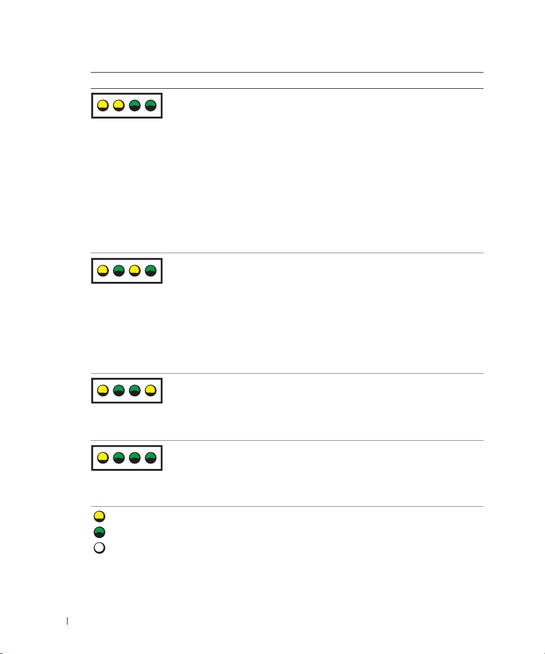
Light Pattern Problem Description Suggested Resolution
ABCD
www.dell.com | support.dell.com
ABCD
Memory modules are detected, but a
memory failure has occurred.
A possible graphics card failure has
occurred.
A possible floppy or hard drive failure
has occurred.
• If you have two or more memory
modules installed, remove the
modules, reinstall one module (see
page 71), and then restart the
computer. If the computer starts
normally, reinstall an additional
module. Continue until you have
identified a faulty module or
reinstalled all modules without error.
• If available, install properly working
memory of the same type into your
computer (see page 71).
• If the problem persists, contact Dell
(see page 121).
• If the computer has a graphics card,
remove the card (see page 81),
reinstall it, and then restart the
computer.
• If the problem still exists, install a
graphics card that you know works and
restart the computer.
• If the problem persists or the
computer has integrated graphics,
contact Dell (see page 121).
Reseat all power and data cables and
restart the computer.
ABCD
ABCD
= yellow
= green
= off
48 Advanced Troubleshooting
A possible USB failure has occurred. Reinstall all USB devices, check cable
connections, and then restart the
computer.
Page 49

Light Pattern Problem Description Suggested Resolution
No memory modules are detected.
ABCD
Memory modules are detected, but a
memory configuration or compatibility
error exists.
ABCD
A possible expansion card failure has
occurred.
ABCD
• If you have two or more memory
modules installed, remove the
modules, reinstall one module (see
page 71), and then restart the
computer. If the computer starts
normally, reinstall an additional
module. Continue until you have
identified a faulty module or
reinstalled all modules without error.
• If available, install properly working
memory of the same type into your
computer (see page 71).
• If the problem persists, contact Dell
(see page 121).
• Ensure that no special memory
module/memory connector placement
requirements exist (see page 70).
• Verify that the memory modules that
you are installing are compatible with
your computer (see page 70).
• If the problem persists, contact Dell
(see page 121).
1
Determine if a conflict exists by
removing a card (not a graphics card)
and restarting the computer (see
page 74).
2
If the problem persists, reinstall the
card that you removed, remove a
different card, and then restart the
computer.
3
Repeat this process for each card. If
the computer starts normally,
troubleshoot the last card removed
from the computer for resource
conflicts (see page 57).
4
If the problem persists, contact Dell
(see page 121).
= yellow
= green
= off
Advanced Troubleshooting 49
Page 50
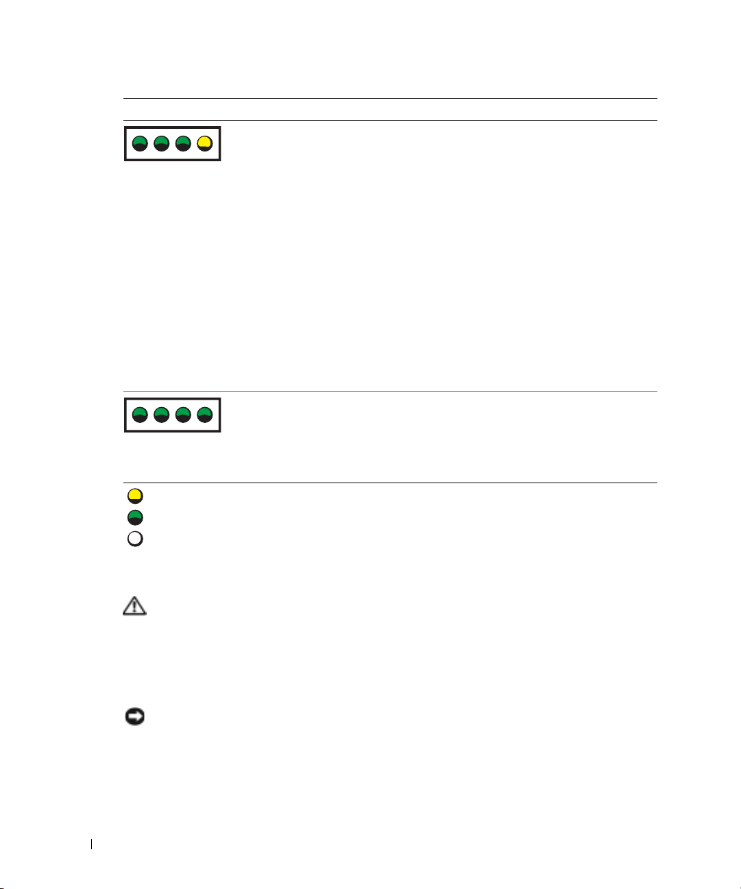
Light Pattern Problem Description Suggested Resolution
ABCD
www.dell.com | support.dell.com
ABCD
= yellow
= green
= off
Another failure has occurred.
The computer is in a normal operating
condition after POST.
• Ensure that the cables are properly
connected to the system board from
the hard drive, CD drive, and DVD
drive (see page 69).
• If there is an error message on your
screen identifying a problem with a
device (such as the floppy drive or
hard drive), check the device to make
sure it is functioning properly.
• The operating system is attempting to
boot from a device (such as the floppy
drive or hard drive); check system
setup (see page 113) to make sure the
boot sequence is correct for the
devices installed on your computer.
• If the problem persists, contact Dell
(see page 121).
None.
Dell Diagnostics
CAUTION: Before you begin any of the procedures in this section, follow the safety instructions
located in the Product Information Guide.
When to Use the Dell Diagnostics
If you experience a problem with your computer, perform the checks in "Solving Problems" (see
page 31) and run the Dell Diagnostics before you contact Dell for technical assistance.
NOTICE: The Dell Diagnostics works only on Dell™ computers.
Start the Dell Diagnostics from either your hard drive (see page 50) or from the
ResourceCD
50 Advanced Troubleshooting
.
Dell Dimension
Page 51

Starting the Dell Diagnostics From Your Hard Drive
1
Turn on (or restart) your computer.
2
When the DELL™ logo appears, press <F12> immediately.
NOTE: If you see a message stating that no diagnostics utility partition has been found, run the Dell
Diagnostics from your ResourceCD
(see page 51).
If you wait too long and the operating system logo appears, continue to wait until you see the
Microsoft
3
When the boot device list appears, highlight
4
When the Dell Diagnostics
®
Windows® desktop. Then shut down your computer (see page 61) and try again.
Main Menu
Boot to Utility Partition
appears, select the test you want to run (see
and press <Enter>
page 52).
Starting the Dell Diagnostics From the ResourceCD
1
Insert the ResourceCD.
2
Shut down and restart the computer (see page 61).
When the DELL logo appears, press <F12> immediately.
If you wait too long and the Windows logo appears, continue to wait until you see the
Windows desktop. Then shut down your computer (see page 61) and try again.
NOTE: The next steps change the boot sequence for one time only. On the next start-up, the computer
boots according to the devices specified in system setup.
When the boot device list appears, highlight
3
4
Select the
5
Select the
6
Ty p e 1 to start the ResourceCD menu.
7
Ty p e 2 to start the Dell Diagnostics.
8
Select
IDE CD-ROM Device
Boot from CD-ROM
option from the CD boot menu.
option from the menu that appears.
Run the 32 Bit Dell Diagnostics
IDE CD-ROM Device
and press <Enter>.
from the numbered list. If multiple versions are listed,
select the version appropriate for your computer.
9
When the Dell Diagnostics
Main Menu
appears, select the test you want to run (see
page 52).
Advanced Troubleshooting 51
Page 52

Dell Diagnostics Main Menu
1
After the Dell Diagnostics loads and the
option you want.
Option Function
Express Test Performs a quick test of devices. This test typically takes 10 to
Extended Test Performs a thorough check of devices. This test typically takes
www.dell.com | support.dell.com
Custom Test Tests a specific device. You can customize the tests you want to
Symptom Tree Lists the most common symptoms encountered and allows you
2
If a problem is encountered during a test, a message appears with an error code and a
description of the problem. Write down the error code and problem description and follow
the instructions on the screen.
If you cannot resolve the error condition, contact Dell (see page 121).
NOTE: The Service Tag for your computer is located at the top of each test screen. If you contact Dell,
technical support will ask for your Service Tag.
If you run a test from the
3
described in the following table for more information.
Main Menu
20 minutes and requires no interaction on your part. Run
Express Test first to increase the possibility of tracing the
problem quickly.
an hour or more and requires you to answer questions
periodically.
run.
to select a test based on the symptom of the problem you are
having.
Custom Test
or
Symptom Tree
screen appears, click the button for the
option, click the applicable tab
Tab Function
Results Displays the results of the test and any error conditions
Errors Displays error conditions encountered, error codes, and the
Help Describes the test and may indicate requirements for running
52 Advanced Troubleshooting
encountered.
problem description.
the test.
Page 53

Ta b Function
Configuration Displays your hardware configuration for the selected device.
The Dell Diagnostics obtains configuration information for all
devices from system setup, memory, and various internal tests,
and it displays the information in the device list in the left pane
of the screen. The device list may not display the names of all
the components installed on your computer or all devices
attached to your computer.
Parameters Allows you to customize the test by changing the test settings.
4
When the tests are completed, if you are running the Dell Diagnostics from the ResourceCD
,
remove the CD.
5
Close the test screen to return to the
restart the computer, close the
Main Menu
Main Menu
screen. To exit the Dell Diagnostics and
screen.
Drivers
What Is a Driver?
A driver is a program that controls a device such as a printer, mouse, or keyboard. All devices require
a driver program.
A driver acts like a translator between the device and any other programs that use the device. Each
device has its own set of specialized commands that only its driver recognizes.
Dell ships your computer to you with required drivers already installed—no further installation or
configuration is needed.
NOTICE: The Dell Dimension ResourceCD may contain drivers for operating systems that are not on your
computer. Ensure that you are installing software appropriate for your operating system.
Many drivers, such as the keyboard driver, come with your Microsoft® Windows® operating
system. You may need to install drivers if you:
• Upgrade your operating system.
• Reinstall your operating system.
• Connect or install a new device.
Identifying Drivers
If you experience a problem with any device, identify whether the driver is the source of your
problem and, if necessary, update the driver.
Advanced Troubleshooting 53
Page 54

Windows XP
1
Click the
2
Under
Pick a Category
3
Click
System
4
In the
System Properties
5
Click
Device Manager
6
Scroll down the list to see if any device has an exclamation point (a yellow circle with a [!]) on
the device icon.
If an exclamation point is next to the device name, you may need to reinstall the driver or
www.dell.com | support.dell.com
install a new driver (see page 53).
Reinstalling Drivers
NOTICE: The Dell Support website at support.dell.com and your Dell Dimension ResourceCD provide
approved drivers for Dell™ computers. If you install drivers obtained from other sources, your computer
might not work correctly.
Using Windows XP Device Driver Rollback
If a problem occurs on your computer after you install or update a driver, use Windows XP Device
Driver Rollback to replace the driver with the previously installed version.
1
Click the
2
Under
Pick a Category
3
Click
System
4
In the
System Properties
5
Click
Device Manager
6
Right-click the device for which the new driver was installed and click
7
Click the
8
Click
Roll Back Driver
If Device Driver Rollback does not resolve the problem, then use System Restore to return your
computer to the operating state that existed before you installed the new driver.
Start
button and click
.
Start
button and click
.
Drivers
tab.
Control Panel
, click
Performance and Maintenance
window, click the
Hardware
.
Control Panel
, click
Performance and Maintenance
window, click the
Hardware
.
.
.
.
tab.
.
.
tab.
Properties
.
Using the ResourceCD
If using Device Driver Rollback or System Restore does not resolve the problem, then reinstall the
driver from the ResourceCD.
1
With the Windows desktop displayed, insert the ResourceCD.
If this is your first time to use the ResourceCD, go to step 2. If not, go to step 5.
2
When the ResourceCD installation program starts, follow the prompts on the screen.
54 Advanced Troubleshooting
Page 55

3
When the
click
4
When you see the Windows desktop, reinsert the ResourceCD.
5
At the
NOTE: The ResourceCD displays drivers only for hardware that came installed in your computer. If you
installed additional hardware, the drivers for the new hardware might not be displayed by the
ResourceCD. If those drivers are not displayed, exit the ResourceCD program. For drivers information,
see the documentation that came with the device.
InstallShield Wizard Complete
Finish
to restart the computer.
Welcome Dell System Owner
window appears, remove the ResourceCD and
screen, click
Next
.
A message stating that the ResourceCD is detecting hardware in your computer appears.
The drivers that are used by your computer are automatically displayed in the
My Drivers—The ResourceCD has identified these components in your system
6
Click the driver that you want to reinstall and follow the instructions on the screen.
window.
If a particular driver is not listed, then that driver is not required by your operating system.
Manually Reinstalling Drivers
1
After extracting the driver files to your hard drive as described in the previous section, click
the
Start
button and right-click
2
Click
Properties
3
Click the
4
Double-click the type of device for which you are installing the driver.
5
Double-click the name of the device for which you are installing the driver.
6
Click the
7
Click
Install from a list or specific location (Advanced)
8
Click
Browse
9
When the name of the appropriate driver appears, click
10
Click
Finish
.
Hardware
Driver
tab and click
tab and click
and browse to the location to which you previously extracted the driver files.
and restart your computer.
My Computer
Device Manager
Update Driver
.
.
.
and click
Next
Next
.
.
Using Microsoft® Windows® XP System Restore
The Microsoft® Windows® XP operating system provides System Restore to allow you to return
your computer to an earlier operating state (without affecting data files) if changes to the
hardware, software, or other system settings have left the computer in an undesirable operating
state. See the Windows Help and Support Center for information on using System Restore. To
access help, see page 11.
NOTICE: Make regular backups of your data files. System Restore does not monitor your data files or
recover them.
Advanced Troubleshooting 55
Page 56

Creating a Restore Point
1
Click the
2
Click
System Restore
3
Follow the instructions on the screen.
Restoring the Computer to an Earlier Operating State
If problems occur after you install a device driver, use Device Driver Rollback (see page 54) to
resolve the problem. If that is unsuccessful, then use System Restore.
NOTICE: Before you restore the computer to an earlier operating state, save and close any open files
and exit any open programs. Do not alter, open, or delete any files or programs until the system
www.dell.com | support.dell.com
restoration is complete.
Click the
1
System Restore
2
Ensure that
3
Click a calendar date to which you want to restore your computer.
The
Select a Restore Point
points. All calendar dates with available restore points appear in boldface type.
4
Select a restore point and click
If a calendar date has only one restore point, then that restore point is automatically selected.
If two or more restore points are available, click the restore point that you prefer.
Start
button and click
Help and Support
.
Start
button, point to
All Programs→
.
Restore my computer to an earlier time
screen provides a calendar that allows you to see and select restore
Next
.
.
Accessories→
System Tools
is selected and click
, and then click
Next
.
5
Click
Next
.
The
Restoration Complete
then the computer restarts.
6
After the computer restarts, click OK.
To change the restore point, you can either repeat the steps using a different restore point, or you
can undo the restoration.
Undoing the Last System Restore
NOTICE: Before you undo the last system restore, save and close all open files and exit any open
programs. Do not alter, open, or delete any files or programs until the system restoration is complete.
Click the
1
System Restore
2
Click
56 Advanced Troubleshooting
Start
Undo my last restoration
screen appears after System Restore finishes collecting data and
button, point to
.
All Programs→ Accessories→ System Tools
and click
Next
.
, and then click
Page 57

3
Click
Next
.
The
System Restore
4
After the computer restarts, click OK.
Enabling System Restore
screen appears and the computer restarts.
If you reinstall Windows XP with less than 200 MB of free hard-disk space available, System
Restore is automatically disabled. To see if System Restore is enabled:
1
Click the
2
Click
3
Click
4
Click the
5
Ensure that
Start
button and click
Control Pane l
Performance and Maintenance
System
.
System Restore
tab.
Turn off System Restore
.
.
is unchecked.
Resolving Software and Hardware Incompatibilities
If a device is either not detected during the operating system setup or is detected but incorrectly
configured, you can use the Hardware Troubleshooter to resolve the incompatibility.
To resolve incompatibilities using the Hardware Troubleshooter:
1
Click the
2
Ty p e
3
Click
4
In the
computer
Start
button and click
hardware troubleshooter
Hardware Troubleshooter
Hardware Troubleshooter
, and click
Next
Help and Support
in the
list, click
.
.
in the
Search
field and click the arrow to start the search.
Search Results
list.
I need to resolve a hardware conflict on my
Reinstalling Microsoft® Windows® XP
NOTICE: You must use Windows XP Service Pack 1 (SP1) or later when you reinstall Windows XP.
Before You Begin
If you are considering reinstalling the Windows XP operating system to correct a problem with a
newly installed driver, first try using Windows XP Device Driver Rollback (see page 54). If Device
Driver Rollback does not resolve the problem, then use System Restore (see page 55) to return your
operating system to the operating state it was in before you installed the new device driver.
NOTICE: Before performing the installation, back up all data files on your primary hard drive. For
conventional hard drive configurations, the primary hard drive is the first drive detected by the computer.
Advanced Troubleshooting 57
Page 58

To reinstall Windows XP, you need the following items:
• Dell™
Operating System
• Dell ResourceCD
NOTE: The ResourceCD contains drivers that were installed during assembly of the computer. Use the
ResourceCD to load any required drivers.
Reinstalling Windows XP
To reinstall Windows XP, perform all the steps in the following sections in the order in which they
are listed.
The reinstallation process can take 1 to 2 hours to complete. After you reinstall the operating
www.dell.com | support.dell.com
system, you must also reinstall the device drivers, virus protection program, and other software.
NOTICE: The Operating System CD provides options for reinstalling Windows XP. The options can
overwrite files and possibly affect programs installed on your hard drive. Therefore, do not reinstall
Windows XP unless a Dell technical support representative instructs you to do so.
NOTICE: To prevent conflicts with Windows XP, disable any virus protection software installed on your
computer before you reinstall Windows XP. See the documentation that came with the software for
instructions.
Booting From the Operating System CD
1
Save and close any open files and exit any open programs.
2
Insert the
3
Restart the computer.
4
Press <F12> immediately after the DELL™ logo appears.
If the operating system logo appears, wait until you see the Windows desktop, and then shut
down the computer and try again.
CD
Operating System
CD. Click
Exit
if
Install Windows XP
message appears.
5
Press the arrow keys to select
6
When the
Windows XP Setup
1
When the
Press any key to boot from CD
Windows XP Setup
Windows now
2
Read the information on the
<F8> to accept the license agreement.
3
If your computer already has Windows XP installed and you want to recover your current
Windows XP data, type
4
If you want to install a new copy of Windows XP, press <Esc> to select that option.
58 Advanced Troubleshooting
CD-ROM
, and press <Enter>.
message appears, press any key.
screen appears, press <Enter> to select
To set up
.
Microsoft Windows Licensing Agreement
r
to select the repair option, and remove the CD.
screen, and press
Page 59

5
Press <Enter> to select the highlighted partition (recommended), and follow the
instructions on the screen.
Windows XP Setup
The
screen appears, and the operating system begins to copy files and
install the devices. The computer automatically restarts multiple times.
NOTE: The time required to complete the setup depends on the size of the hard drive and the speed of
your computer.
NOTICE: Do not press any key when the following message appears: Press any key to boot
from the CD.
6
When the
location and click
7
Enter your name and organization (optional) in the
click
8
If you are reinstalling Windows XP Home Edition
window, enter a name for your computer (or accept the name provided) and click
If you are reinstalling Windows XP Professional
Password
password, and click
9
If the
Next
10
Enter the date, time, and time zone in the
11
If the
12
If you are reinstalling Windows XP Professional and you are prompted to provide further
Regional and Language Options
Next
.
screen appears, select the settings for your
Personalize Your Software
Next
.
, at the
, at the
What's your computer's name
Computer Name and Administrator
window, enter a name for your computer (or accept the one provided) and a
Next
.
Modem Dialing Information
screen appears, enter the requested information and click
.
Networking Settings
Date and Time Settings
screen appears, click
Typical
and click
window, and click
Next
.
screen, and
Next
information regarding your network configuration, enter your selections. If you are unsure of
your settings, accept the default selections.
Windows XP installs the operating system components and configures the computer. The
computer automatically restarts.
.
Next
.
NOTICE: Do not press any key when the following message appears: Press any key to boot
from the CD.
13
14
15
16
17
18
When the
When the
click
When the
click
When the
Click
Click
Welcome to Microsoft
How will this computer connect to the Internet?
Skip
.
Ready to register with Microsoft?
Next
.
Who will use this computer?
Next
.
Finish
to complete the setup, and remove the CD.
screen appears, click
Next
screen appears, select
screen appears, you can enter up to five users.
.
message appears,
No, not at this time
Advanced Troubleshooting 59
and
Page 60

19
Reinstall the appropriate drivers with the ResourceCD (see page 54).
20
Reinstall your virus protection software.
21
Reinstall your programs.
NOTE: To reinstall and activate your Microsoft Office or Microsoft Works Suite programs, you need the
Product Key number located on the back of the Microsoft Office or Microsoft Works Suite CD sleeve.
www.dell.com | support.dell.com
60 Advanced Troubleshooting
Page 61

Removing and Installing Parts
Before You Begin
This chapter provides procedures for removing and installing the components in your computer.
Unless otherwise noted, each procedure assumes that the following conditions exist:
• You have performed the steps in "Turning Off Your Computer" (see page 61) and "Before
Working Inside Your Computer" (see page 62).
• You have read the safety information in your Dell™
• A component can be replaced by performing the removal procedure in reverse order.
Recommended Tools
The procedures in this document may require the following tools:
• Small flat-blade screwdriver
• Phillips screwdriver
• Flash BIOS update program floppy disk or CD
Turning Off Your Computer
NOTICE: To avoid losing data, save and close any open files and exit any open programs before you turn
off your computer.
Shut down the operating system:
1
a
Save and close any open files, exit any open programs, click the
click
Turn Off Computer
b
In the
Turn off computer
The computer turns off after the operating system shutdown process finishes.
2
Ensure that the computer and any attached devices are turned off. If your computer and
attached devices did not automatically turn off when you shut down your operating system,
press and hold the power button for 4 seconds.
.
window, click
Tur n off
Product Information Guide.
Start
button, and then
.
Removing and Installing Parts 61
Page 62

Before Working Inside Your Computer
Use the following safety guidelines to help protect your computer from potential damage and to
help ensure your own personal safety.
CAUTION: Before you begin any of the procedures in this section, follow the safety instructions
located in the Product Information Guide.
CAUTION: Handle components and cards with care. Do not touch the components or contacts on a
card. Hold a card by its edges or by its metal mounting bracket. Hold a component such as a processor
by its edges, not by its pins.
NOTICE: Only a certified service technician should perform repairs on your computer. Damage due to
servicing that is not authorized by Dell is not covered by your warranty.
www.dell.com | support.dell.com
NOTICE: When you disconnect a cable, pull on its connector or on its strain-relief loop, not on the cable
itself. Some cables have a connector with locking tabs; if you are disconnecting this type of cable, press
in on the locking tabs before you disconnect the cable. As you pull connectors apart, keep them evenly
aligned to avoid bending any connector pins. Also, before you connect a cable, ensure that both
connectors are correctly oriented and aligned.
NOTICE: To avoid damaging the computer, perform the following steps before you begin working inside
the computer.
1
Turn off your computer (see page 61).
NOTICE: To disconnect a network cable, first unplug the cable from your computer and then unplug it
from the network wall jack.
Disconnect any telephone or telecommunication lines from the computer.
2
3
Disconnect your computer and all attached devices from their electrical outlets, and then
press the power button to ground the system board.
CAUTION: To guard against electrical shock, always unplug your computer from the electrical outlet
before opening the cover.
Open the computer cover (see page 67).
4
NOTICE: Before touching anything inside your computer, ground yourself by touching an unpainted
metal surface, such as the metal at the back of the computer. While you work, periodically touch an
unpainted metal surface to dissipate any static electricity that could harm internal components.
62 Removing and Installing Parts
Page 63

Front and Back View of the Computer
Front View
1
2
3
4
1
hard-drive activity light The hard-drive light is on when the computer reads data from or writes data to the
hard drive. The light might also be on when a device such as your CD player is
operating.
2
power button
3
drive door Open the drive door to access the floppy and CD/DVD drives.
4
front-panel door
Press to turn on the computer.
NOTICE: To avoid losing data, do not use the power button to turn off the
computer. Instead, perform an operating system shutdown.
Open the door to use the front-panel connectors.
NOTE: The front door is removable; if you remove it or accidentally knock it off its
hinges, it snaps back in place. For instructions on how to reattach the door, see
page 105.
Removing and Installing Parts 63
Page 64
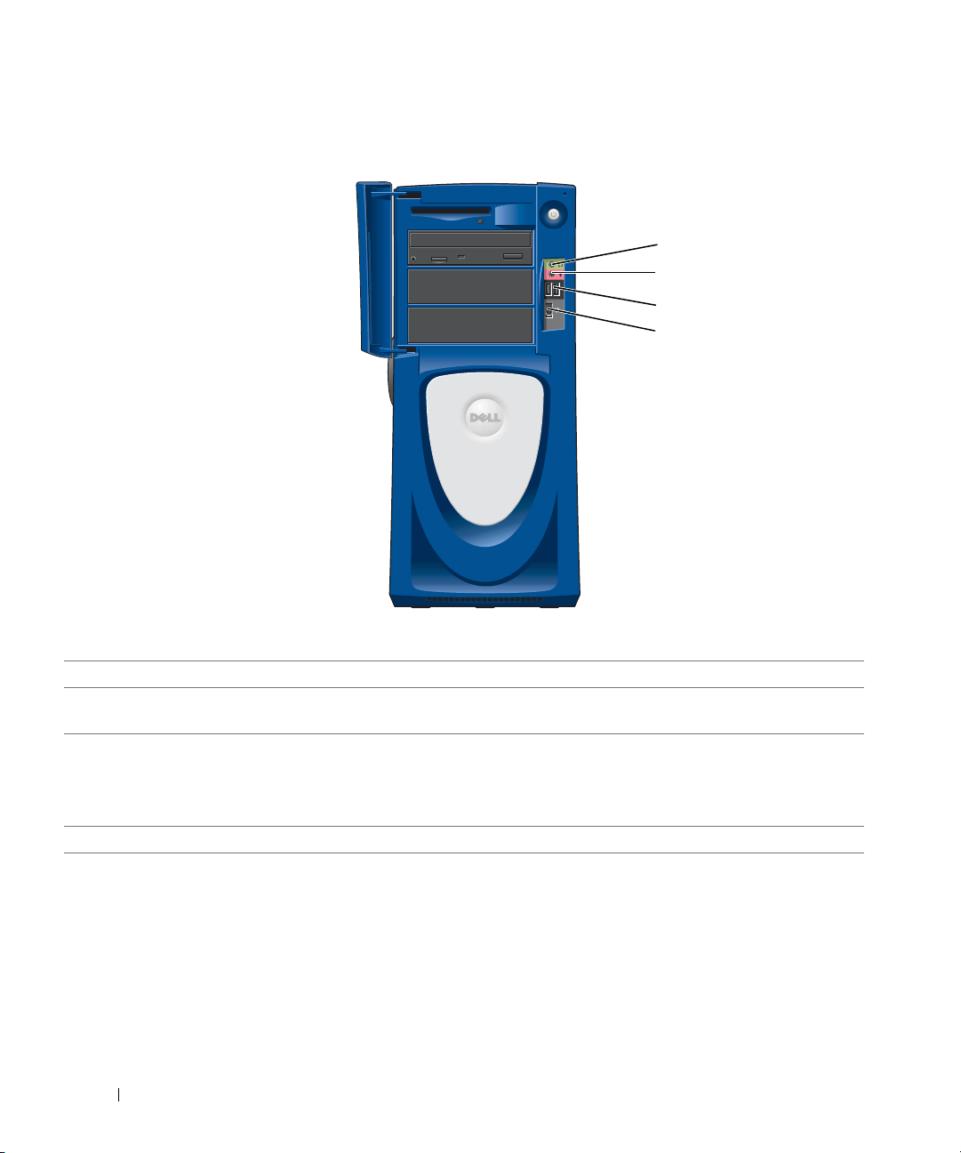
Front View (Doors Open)
www.dell.com | support.dell.com
1
2
3
4
1
headphone connector
microphone connector Use the microphone connector to attach a personal computer microphone for voice or
2
3
USB 2.0 connectors (2) Use the front USB connectors for devices that you connect occasionally, such as joysticks
4
IEEE 1394 connector Attach high-speed serial multimedia devices, such as digital video cameras.
Use the headphone connector to attach headphones and most kinds of speakers.
musical input into a sound or telephony program.
or cameras.
It is recommended that you use the back USB connectors for devices that typically
remain connected, such as printers and keyboards.
64 Removing and Installing Parts
Page 65

Back View
12
13
14
15
16
17
18
19
1
processor fans (2) For optimal cooling, two processor fans are provided. Do not block the vents.
2
cover latch release
network adapter connector To attach your computer to a network or broadband device, connect one end of a
3
To open the computer, lay the computer on its side with the cover latch release at the
top and then push the latch to the left. See "Opening the Computer Cover" on
page 67.
network cable to either a network jack or to your network or broadband device. Connect
the other end of the network cable to the network adapter connector on the back panel
of your computer. A click indicates that the network cable has been securely attached.
1
2
3
4
5
6
7
8
9
10
11
NOTE: Do not plug a telephone cable into the network connector.
On computers with a network connector card, use the connector on the card.
network or
broadband jack
It is recommended that you use Category 5 wiring and connectors for your network. If
you must use Category 3 wiring, force the network speed to 10 Mbps to ensure reliable
operation.
Removing and Installing Parts 65
Page 66

4 TV-OUT connector Connects your computer to a TV. For more information, see "Connecting Two
Monitors" on page 15.
5
DVI video connector If your monitor has a DVI connector, plug it into the DVI connector on the computer. If
your monitor has a VGA connector, plug it into the VGA connector on the computer.
6
VGA video connector If your monitor has a DVI connector, plug it into the DVI connector on the computer. If
your monitor has a VGA connector, plug it into the VGA connector on the computer.
7
security cable slot Use a security cable with the slot to help secure your computer.
8 sound card connectors
www.dell.com | support.dell.com
9 padlock ring Insert a padlock to lock the computer cover.
10
optional modem
connector
• Line-in connector — Use the blue line-in connector to attach a record/playback
device such as a cassette player, CD player, or VCR.
• Microphone connector — Use the pink microphone connector to attach a personal
computer microphone for voice or musical input into a sound or telephony program.
• Line-out connector — Use the green line-out connector to attach headphones and
most speakers with integrated amplifiers.
• Surround connector — Use the black surround connector to attach multichannelcapable speakers.
•
Center/Low-Frequency Effects (LFE) connector
connector to attach your subwoofer.
If you have a modem, connect a telephone cable to the modem connector (optional).
— Use the yellow center/LFE
NOTE: For optimum performance, install a modem card only in PCI slot 2, 3, or 4.
NOTE: Do not plug a telephone cable into the network connector.
power connector Insert the power cable.
11
12
serial connector (COM 1) Connect a serial device, such as a handheld device, to the serial port.
13
parallel connector Connect a parallel device, such as a printer, to the parallel connector. If you have a USB
printer, plug it into a USB connector.
14
diagnostic lights (4) Use the lights to help you troubleshoot a computer problem based on the diagnostic
code. For more information, see "Diagnostics Lights" on page 47.
15
keyboard connector If you have a standard keyboard, plug it into the purple keyboard connector. If you have a
USB keyboard, plug it into a USB connector.
16
mouse connector Plug a standard mouse into the green mouse connector. Turn off the computer and any
attached devices before you connect a mouse to the computer. If you have a USB mouse,
plug it into a USB connector.
17
USB 2.0 connectors (6) Use the back USB connectors for devices that typically remain connected, such as
printers and keyboards.
It is recommended that you use the front USB connectors for devices that you connect
occasionally, such as joysticks or cameras.
18
card slots
19
power supply fans For optimal cooling, two power supply fans are provided. Do not block the vents.
Access connectors for any installed PCI cards (four slots) and PCI Express cards (one
x16 slot and one x1 slot).
66 Removing and Installing Parts
Page 67

Opening the Computer Cover
CAUTION: Before you begin any of the procedures in this section, follow the safety instructions
located in the Product Information Guide.
CAUTION: To prevent static damage to components inside your computer, discharge static electricity
from your body before you touch any of your computer’s electronic components. You can do so by
touching an unpainted metal surface on the computer chassis.
Follow the procedures in "Before You Begin" (see page 61).
1
2
Lay the computer on its side so that the arrow on the bottom of the computer points up.
NOTICE: Ensure that sufficient space exists to accommodate the open cover—at least 30 cm (1 ft) of
desk top space.
Slide the cover release latch toward the top of the computer.
3
4
Raise the cover, and pivot it toward the front of the computer.
cover release latch
security cable slot
padlock ring
Removing and Installing Parts 67
Page 68

Inside View of Your Computer
floppy drive
hard drive
shroud
www.dell.com | support.dell.com
processor
airflow shroud
processor fan
CD/DVD drive
power supply fans (2)
PCI card shroud
and fan
system board
power supply
68 Removing and Installing Parts
Page 69
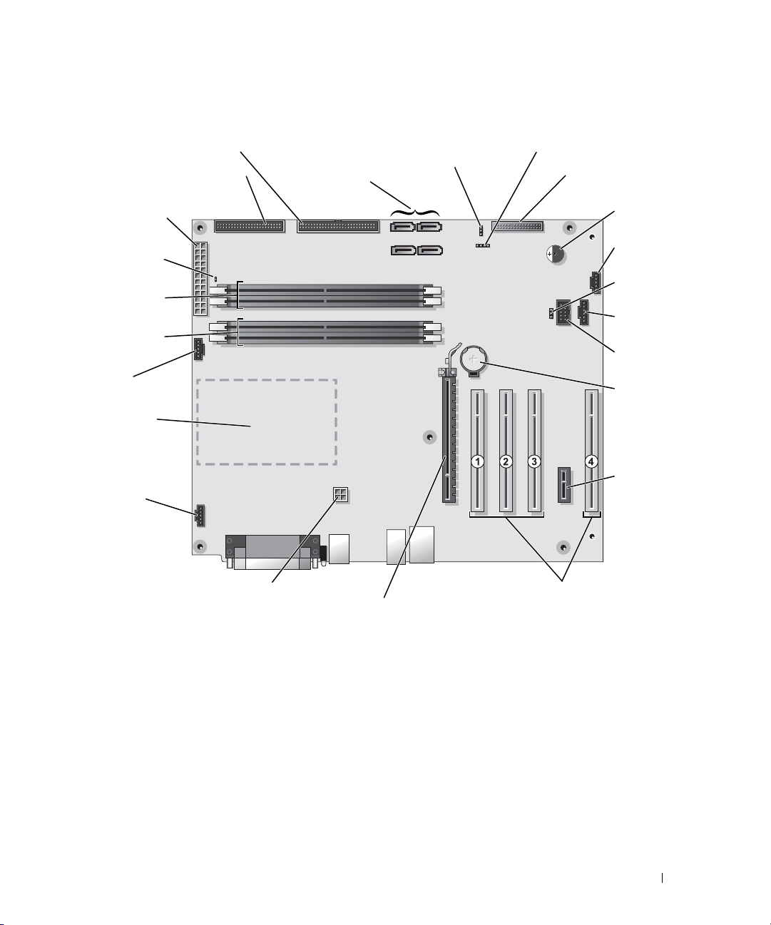
System Board Components
f
hard-drive connector (PRI_IDE)
loppy-drive connector (FLOPPY)
main power
connector (PWR)
auxiliary power
LED (AUX_PWR)
memory module
connectors (2, 4)
memory module
connectors (1, 3)
processor fan
(CPU FAN)
processor and heatsink connector
rear fan connector
(REAR FAN1)
serial ATA connectors
(SATA-0, SATA-1,
SATA- 2, SATA - 3)
password jumper
(PASS)
SCSI LED header (SCSI LED)
front-panel connector
(FRONT PANEL)
internal speaker
(SPKR)
card fan connector
(PCI_FAN)
clear CMOS
jumper (CMOS)
backlight
connector (LED)
IEEE 1394
connector (1394)
battery socket
(BATTERY)
PCI-Express x1
card connector
power connector (12V PWR)
PCI-Express x16
card connector
PCI card connectors (PCI
SLOT 1, PCI SLOT 2, PCI
SLOT 3, PCI SLOT 4)
Removing and Installing Parts 69
Page 70

Memory
You can increase your computer memory by installing memory modules on the system board.
Your computer supports DDR2 memory. For additional information on the type of memory
supported by your computer, see "Memory" on page 109.
DDR2 Memory Overview
• DDR2 memory modules should be installed in
technology
will continue to operate, but with a slight reduction in performance. See the label on the
upper-right corner of the module to determine the module’s capacity.
www.dell.com | support.dell.com
NOTE: Always install DDR2 memory modules in the order indicated on the system board.
The recommended memory configurations are:
– A pair of matched memory modules installed in DIMM connectors 1 and 2
or
pairs of matched memory size, speed, and
. If the DDR2 memory modules are not installed in matched pairs, the computer
– A pair of matched memory modules installed in DIMM connectors 1 and 2 and another
matched pair installed in DIMM connectors 3 and 4
NOTICE: Do not install ECC memory modules.
• If you install mixed pairs of PC2-3200 (DDR2 400-MHz) and PC2-4200 (DDR2 533-MHz)
memory, the modules function at the slowest speed installed.
• Be sure to install a single memory module in DIMM connector 1, the connector closest to the
processor, before you install modules in the other connectors.
70 Removing and Installing Parts
Page 71

matched pair of memory modules in DIMM
connectors 3 and 4 (black securing clips)
matched pair of modules in DIMM
connectors 1 and 2 (white securing clips)
NOTE: Memory purchased from Dell is covered under your computer warranty.
NOTICE: If you remove your original memory modules from the computer during a memory upgrade,
keep them separate from any new modules that you may have, even if you purchased the new modules
from Dell. If possible, do not pair an original memory module with a new memory module. Otherwise, your
computer may not start properly. You should install your original memory modules in pairs either in DIMM
connectors 1 and 2 or DIMM connectors 3 and 4.
Addressing Memory With 4-GB Configurations
Your computer supports a maximum of 4 GB of memory when you use four 1-GB DIMMs. Current
operating systems, such as Microsoft
®
Windows® XP, can only use a maximum of 4 GB of address
space; however, the amount of memory available to the operating system is less than 4 GB. Certain
components within the computer require address space in the 4-GB range. Any address space
reserved for these components cannot be used by computer memory.
Installing Memory
CAUTION: Before you begin any of the procedures in this section, follow the safety instructions
located in the Product Information Guide.
NOTICE: To prevent static damage to components inside your computer, discharge static electricity
from your body before you touch any of your computer’s electronic components. You can do so by
touching an unpainted metal surface on the computer chassis.
Follow the procedures in "Before You Begin" on page 61.
1
2
Lay the computer on its side so that the system board is on the bottom of the inside of the
computer.
Removing and Installing Parts 71
Page 72
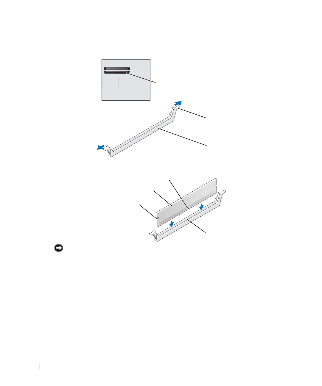
3
Press out the securing clip at each end of the memory module connector.
www.dell.com | support.dell.com
4
Align the notch on the bottom of the module with the crossbar in the connector.
memory connector
closest to processor
securing clips (2)
connector
notch
memory module
cutouts (2)
NOTICE: To avoid damage to the memory module, press the module straight down into the connector
while you apply equal force to each end of the module.
Insert the module into the connector until the module snaps into position.
5
If you insert the module correctly, the securing clips snap into the cutouts at each end of the
module.
72 Removing and Installing Parts
crossbar
Page 73
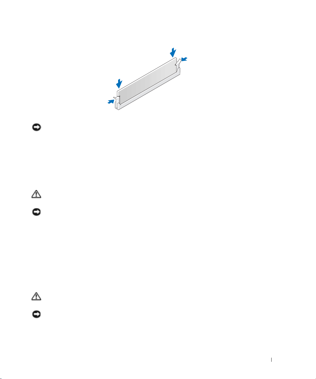
6
Close the computer cover.
NOTICE: To connect a network cable, first plug the cable into the network wall jack and then plug it into
the computer.
Connect your computer and devices to electrical outlets, and turn them on.
7
8
Right-click the
9
Click the
10
To verify that the memory is installed correctly, check the amount of memory (RAM) listed.
My Computer
General
tab.
icon and click
Properties
.
Removing Memory
CAUTION: Before you begin any of the procedures in this section, follow the safety instructions
located in the Product Information Guide.
NOTICE: To prevent static damage to components inside your computer, discharge static electricity
from your body before you touch any of your computer’s electronic components. You can do so by
touching an unpainted metal surface on the computer chassis.
Follow the procedures in "Before You Begin" on page 61.
1
2
Press out the securing clip at each end of the memory module connector.
3
Grasp the module and pull up.
If the module is difficult to remove, gently ease the module back and forth to remove it from
the connector.
Cards
CAUTION: Before you begin any of the procedures in this section, follow the safety instructions
located in the Product Information Guide.
NOTICE: To prevent static damage to components inside your computer, discharge static electricity
from your body before you touch any of your computer’s electronic components. You can do so by
touching an unpainted metal surface on the computer chassis.
Removing and Installing Parts 73
Page 74

Your Dell™ computer provides the following slots for PCI and PCI Express cards:
• Four PCI card slots
• One PCI Express x16 card slot
• One PCI Express x1 card slot
PCI Cards
www.dell.com | support.dell.com
If you are installing or replacing a card, follow the procedures in the next section. If you are
removing but not replacing a card, see "Removing a PCI Card" on page 76.
If you are replacing a card, remove the current driver for the card from the operating system.
If you are installing or replacing a PCI Express card, see "Installing a PCI Express Card" on page 78.
Installing a PCI Card
1
Follow the procedures in "Before You Begin" on page 61.
2
Press the lever on the card retention arm and raise the retention arm.
retention arm
filler bracket
74 Removing and Installing Parts
lever
PCI card
edge connector
card connector
Page 75
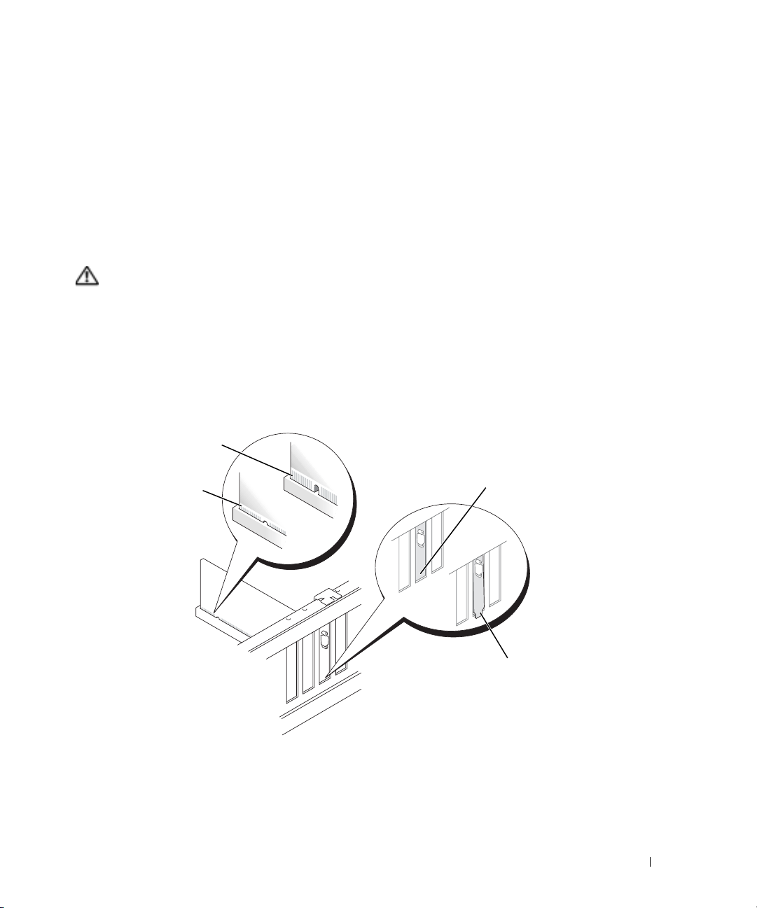
3
If you are installing a new card, remove the filler bracket to create a card-slot opening. Then
continue with step 5.
4
If you are replacing a card that is already installed in the computer, remove the card.
If necessary, disconnect any cables connected to the card. Grasp the card by its top corners,
and ease it out of its connector.
5
Prepare the card for installation.
See the documentation that came with the card for information on configuring the card,
making internal connections, or otherwise customizing it for your computer.
CAUTION: Some network adapters automatically start the computer when they are connected to a
network. To guard against electrical shock, be sure to unplug your computer from its electrical outlet
before installing any cards.
Place the card in the connector and press down firmly. Ensure that the card is fully seated in
6
the slot.
If the card is full-length, insert the end of the card into the card guide bracket as you lower the
card toward its connector on the system board. Insert the card firmly into the card connector
on the system board.
not fully seated card
fully seated card
7
Before you lower the retention arm, ensure that:
bracket within slot
bracket caught
outside of slot
• The tops of all cards and filler brackets are flush with the alignment bar.
• The notch in the top of the card or filler bracket fits around the alignment guide.
8
Press the retention arm into place, securing the card(s) in the computer.
Removing and Installing Parts 75
Page 76

www.dell.com | support.dell.com
NOTICE: Do not route card cables over or behind the cards. Cables routed over the cards can prevent
the computer cover from closing properly or cause damage to the equipment.
Connect any cables that should be attached to the card.
9
See the documentation for the card for information about the card’s cable connections.
NOTICE: To connect a network cable, first plug the cable into the network wall jack and then plug it into
the computer.
Close the computer cover, reconnect the computer and devices to electrical outlets, and then
10
turn them on.
11
If you installed an add-in network adapter and you want to disable the integrated network
adapter:
a
Enter system setup (see page 113), select
setting for
b
Connect the network cable to the add-in network adapter’s connectors. Do not connect
the network cable to the integrated connector on the back panel.
12
Install any drivers required for the card as described in the card documentation.
alignment guide
alignment bar
filler bracket
Network Interface Card
retention arm
Integrated Devices,
to
Off
.
and then change the
Removing a PCI Card
1
Follow the procedures in "Before You Begin" on page 61.
2
Press the lever on the card retention arm and raise the retention arm.
3
If necessary, disconnect any cables connected to the card.
4
Grasp the card by its top corners, and ease it out of its connector.
76 Removing and Installing Parts
Page 77

5
If you are removing the card permanently, install a filler bracket in the empty card-slot
opening.
If you need a filler bracket, contact Dell (see page 121).
NOTE: Installing filler brackets over empty card-slot openings is necessary to maintain FCC certification
of the computer. The brackets also keep dust and dirt out of your computer.
Lower the retention arm and press it into place, securing the card(s) in the computer.
6
NOTICE: To connect a network cable, first plug the cable into the network wall jack and then plug it into
the computer.
Close the computer cover, reconnect the computer and devices to electrical outlets, and turn
7
them on.
8
Remove the card’s driver from the operating system.
9
If you removed an add-in network connector and want to enable the integrated network
adapter:
a
Enter system setup, select
Interface Card
b
Connect the network cable to the integrated connector on the back panel of the
to On.
Integrated Devices
, and then change the setting for
computer.
PCI Express Cards
Your computer supports one PCI Express x16 card and one PCI Express x1 card.
Network
PCI Express x16
card
PCI Express x16
card slot
PCI Express x1
card
PCI Express x1
card slot
If you are installing or replacing a PCI Express card, follow the procedures in the next section. If
you are removing but not replacing a PCI Express card, see "Removing a PCI Express Card" on
page 81.
If you are replacing a card, remove the current driver for the card from the operating system.
If you are installing or replacing a PCI card, see "Installing a PCI Card" on page 74.
Removing and Installing Parts 77
Page 78

Installing a PCI Express Card
1
Follow the procedures in "Before You Begin" on page 61.
2
Press the lever on the card retention arm and raise the retention arm.
www.dell.com | support.dell.com
tab
top of retention
mechanism
lever
x16 card
filler bracket
retention arm
securing slot
securing tab
edge connector
card connector
x1 card
edge connector
card connector
78 Removing and Installing Parts
Page 79

3
If you are installing a new card, remove the filler bracket to create a card-slot opening. Then
continue with step 5.
4
If you are replacing a card that is already installed in the computer, remove the card.
If necessary, disconnect any cables connected to the card. If your card includes a retention
mechanism, remove the top of the retention mechanism by pressing the tab and pulling up
on the top. Gently pull the securing tab, grasp the card by its top corners, and ease it out of its
connector.
5
Prepare the card for installation.
See the documentation that came with the card for information on configuring the card,
making internal connections, or otherwise customizing it for your computer.
CAUTION: Some network adapters automatically start the computer when they are connected to a
network. To guard against electrical shock, be sure to unplug your computer from its electrical outlet
before installing any cards.
If you are installing the card into the x16 card connector, position the card so the securing slot
6
is aligned with the securing tab, and gently pull the securing tab.
7
Place the card in the connector and press down firmly. Ensure that the card is fully seated in
the slot.
If the card is full-length, insert the end of the card into the card guide bracket as you lower the
card toward its connector on the system board. Insert the card firmly into the card connector
on the system board.
not fully seated card
fully seated card
bracket within slot
bracket caught
outside of slot
Removing and Installing Parts 79
Page 80

8
If you replaced a card that was already installed in the computer and you removed the top of
the retention mechanism, you can reinstall the top.
9
Before you lower the retention arm, ensure that:
• The tops of all cards and filler brackets are flush with the alignment bar.
• The notch in the top of the card or filler bracket fits around the alignment guide.
10
Press the retention arm into place, securing the card(s) in the computer.
www.dell.com | support.dell.com
retention arm
alignment guide
alignment bar
filler bracket
NOTICE: Do not route card cables over or behind the cards. Cables routed over the cards can prevent
the computer cover from closing properly or cause damage to the equipment.
Connect any cables that should be attached to the card.
11
See the documentation that came with the card for information about the card’s cable
connections.
NOTICE: To connect a network cable, first plug the cable into the network wall jack and then plug it into
the computer.
Close the computer cover, reconnect the computer and devices to electrical outlets, and then
12
turn them on.
13
If you installed an add-in network adapter and you want to disable the integrated network
adapter:
a
Enter system setup (see page 113), select
setting to
b
Connect the network cable to the add-in network adapter’s connectors. Do not connect
Off
the network cable to the integrated connector on the back panel.
14
Install any drivers required for the card as described in the card documentation.
80 Removing and Installing Parts
Network Controller,
and then change the
.
Page 81

Removing a PCI Express Card
1
Follow the procedures in "Before You Begin" on page 61.
2
Press the lever on the card retention arm and raise the retention arm.
3
If necessary, disconnect any cables connected to the card.
4
If your card includes a retention mechanism, remove the top of the retention mechanism by
pressing the tab and pulling up on the top.
5
Gently pull back the securing tab, grasp the card by its top corners, and then ease it out of its
connector.
6
If you are removing the card permanently, install a filler bracket in the empty card-slot
opening.
If you need a filler bracket, contact Dell (see page 121).
NOTE: Installing filler brackets over empty card-slot openings is necessary to maintain FCC certification
of the computer. The brackets also keep dust and dirt out of your computer.
Lower the retention arm and press it into place, securing the card(s) in the computer.
7
NOTICE: To connect a network cable, first plug the cable into the network wall jack and then plug it into
the computer.
Close the computer cover, reconnect the computer and devices to electrical outlets, and then
8
turn them on.
9
Remove the card’s driver from the operating system.
10
If you removed an add-in network connector:
a
Enter system setup (see page 114), select
setting to
b
Connect the network cable to the integrated connector on the back panel of the
On
.
Network Controller
, and then change the
computer.
11
Install any drivers required for the card as described in the card documentation.
Removing and Installing Parts 81
Page 82

Drives
Your computer supports a combination of these devices:
• Up to three hard drives
• One floppy drive
• Up to two CD or DVD drives
www.dell.com | support.dell.com
floppy drive
CD/DVD drive(s)
hard drive(s)
General Installation Guidelines
Connect serial ATA hard drives to the system board connectors labeled SATA-0, SATA-1, SATA-2,
or SATA-3. Connect CD/DVD drives to the connector labeled PRI IDE.
When you connect two IDE devices to a single IDE interface cable and configure them for the
cable select setting, the device attached to the last connector on the interface cable is the primary
or the boot device (drive 0), and the device attached to the middle connector on the interface cable
is the secondary device (drive 1). See the drive documentation in your upgrade kit for information
on configuring devices for the cable select setting.
82 Removing and Installing Parts
Page 83

Connecting Drive Cables
When you install a drive, you connect two cables—a DC power cable and a data cable—to the back
of the drive and to the system board. Some drives may also have an audio connector; one end of the
audio cable attaches to the drive connector and the other end attaches to the system board.
Drive Interface Connectors
Serial ATA Connector
interface cable
interface connector
Most interface connectors are keyed for correct insertion; that is, a notch or a missing pin on one
connector matches a tab or a filled-in hole on the other connector.
When you connect an IDE cable, ensure that you align the colored stripe with the pin 1 connector.
When you disconnect an IDE cable, grasp the colored pull tab and pull until the connector
detaches.
When connecting and disconnecting a serial ATA cable, hold the cable by the connector at
each end.
NOTE: The system board serial ATA connector may have an attached cover or shroud.
Removing and Installing Parts 83
Page 84

Power Cable Connector
www.dell.com | support.dell.com
Hard Drive
CAUTION: Before you begin any of the procedures in this section, follow the safety instructions
located in the Product Information Guide.
NOTICE: To avoid damage to the drive, do not set it on a hard surface. Instead, set the drive on a
surface, such as a foam pad, that will sufficiently cushion it.
1
If you are replacing a hard drive that contains data you want to keep, back up your files before
you remove the hard drive.
2
Follow the procedures in "Before You Begin" on page 61.
power input
connector
power cable
Removing a Hard Drive
1
Press in on the top shroud tabs
and tilt the shroud back.
2
Lift the shroud away from the
hard drive.
84 Removing and Installing Parts
Page 85

3
Disconnect the power and hard-drive cables from the drive and from the system board.
hard-drive cable
power cable
4
Press in on the tabs on each side of the drive and slide the drive up and out.
tabs (2)
hard drive
system board connector
Installing a Hard Drive
1
Unpack the replacement hard drive, and prepare it for installation.
2
Check the documentation for the drive to verify that it is configured for your computer.
3
If your replacement hard drive does not have the bracket rails attached, remove the rails from
the old drive by removing the two screws that secure each rail to the drive. Attach the bracket
rails to the new drive by aligning the screw holes on the drive with the screw holes on the
bracket rails and then inserting and tightening all four screws (two screws on each rail).
Removing and Installing Parts 85
Page 86
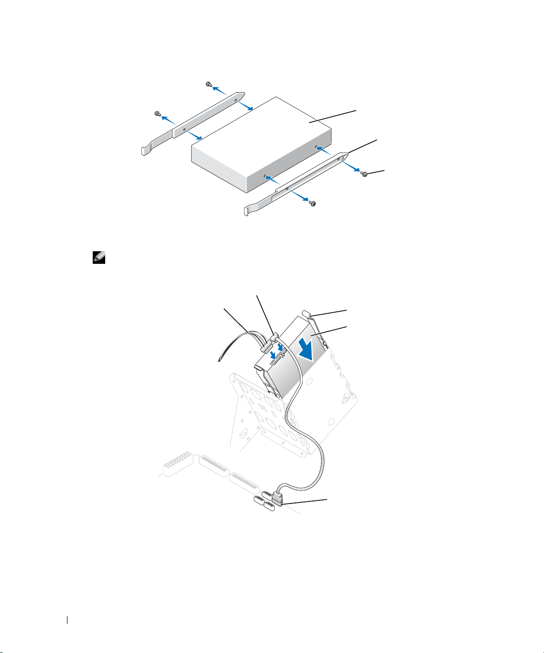
drive
bracket rails (2)
screws (4)
www.dell.com | support.dell.com
4
Install the hard drive into the computer by gently sliding the drive into place until the tabs
securely click into position.
NOTE: If you are installing a hard drive in the lower bay, place the drive in the bay so that the power
connector is on the left-hand side (opposite of the top hard drive)
.
hard-drive cable
power cable
tabs (2)
hard drive
system board connector
5
Connect a power cable to the drive.
6
Connect the hard-drive cable to the drive and to the system board (see page 69).
7
Check all connectors to be certain that they are properly cabled and firmly seated.
86 Removing and Installing Parts
Page 87

NOTICE: When replacing the hard-drive shroud, ensure that all the cables are properly routed.
Insert the bottom tabs of the shroud in to the holes on the drive cage and rotate the
8
shroud up.
9
Press in on the top tabs and lock them in to place.
10
Gently press on the shroud to ensure it is secure.
11
Close the computer cover (see page 108).
NOTICE: To connect a network cable, first plug the cable into the network wall jack and then plug it into
the computer.
12
Connect your computer and devices to electrical outlets, and turn them on.
See the documentation that came with the drive for instructions on installing any software
required for drive operation.
13
If the drive you just installed is the primary drive, insert a bootable floppy disk into drive A.
14
Turn on the computer.
15
Enter system setup (see page 114), and update the appropriate
Drive
option.
Removing and Installing Parts 87
Page 88

16
Exit system setup, and restart the computer.
17
Partition and logically format your drive before you proceed to the next step.
See the documentation for your operating system for instructions.
18
Test the hard drive by running the Dell Diagnostics (see page 50).
19
If the drive you just installed is the primary drive, install your operating system on the hard
drive.
Adding a Second Hard Drive
CAUTION: Before you begin any of the procedures in this section, follow the safety instructions
located in the Product Information Guide.
www.dell.com | support.dell.com
CAUTION: To guard against electrical shock, always unplug your computer from the electrical outlet
before opening the cover.
NOTICE: To avoid damage to the drive, do not set it on a hard surface. Instead, set the drive on a
surface, such as a foam pad, that will sufficiently cushion it.
Check the documentation for the drive to verify that it is configured for your computer.
1
2
Follow the procedures in "Before You Begin" on page 61.
3
Remove the two plastic rails from the inside of the hard-drive bay by gently pulling the rails
up and out of the bay.
4
Attach the rails to the hard drive using the two screws attached to the rails.
Ensure that the rail tabs are positioned at the back of the hard drive.
NOTICE: Do not install any drive into the lower hard-drive bay until you have removed the green drive
rails from the inside of the hard-drive bay.
Remove the first hard drive from the upper bay and install it in the lower bay:
5
a
Disconnect the power and the hard-drive cables from the back of the first hard drive.
b
Press in the two rail tabs and pull the first hard drive out of the upper bay.
c
Gently slide the first hard drive into the lower bay until you hear a click.
d
Reconnect the power and hard-drive cables to the back of the first hard drive.
6
Gently slide the new hard drive into the upper bay until you hear a click.
88 Removing and Installing Parts
Page 89
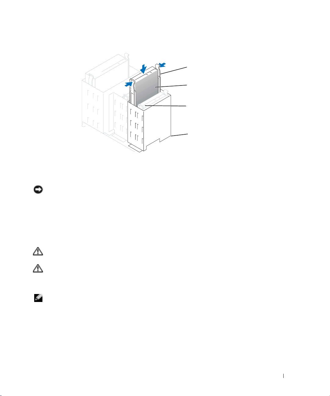
rail tabs (2)
second hard drive
in upper bay
first hard drive in
lower bay
hard drive bay
7
Connect a power cable to the drive.
8
Connect the hard-drive cable to the drive and to the system board (see page 69).
9
Close the computer cover (see page 108).
NOTICE: To connect a network cable, first plug the cable into the network device and then plug it into
the computer.
Connect your computer and devices to their electrical outlets, and turn them on.
10
See the documentation that came with the drive for instructions on installing any software
required for drive operation.
Floppy Drive
CAUTION: Before you begin any of the procedures in this section, follow the safety instructions
located in the Product Information Guide.
CAUTION: To guard against electrical shock, always unplug your computer from the electrical outlet
before opening the cover.
Follow the procedure in "Before You Begin" on page 61.
NOTE: If you are adding a floppy drive, see "Installing a Floppy Drive" on page 90.
Removing a Floppy Drive
1
Disconnect the power and data cables from the back of the floppy drive.
2
Disconnect the other end of the data cable from the system board.
Removing and Installing Parts 89
Page 90

data cable
power cable
tabs (2)
floppy drive
www.dell.com | support.dell.com
3
Press inward on the two tabs on the sides of the drive, slide the drive upward, and remove it
from the floppy-drive bay.
Installing a Floppy Drive
1
If you are replacing a drive and the new drive does not have the bracket rails attached, remove
the rails from the old drive by removing the two screws that secure each rail to the drive.
Attach the bracket to the new drive by aligning the screw holes on the drive with the screw
holes on the bracket rails and then inserting and tightening all four screws (two screws on
each rail).
90 Removing and Installing Parts
Page 91
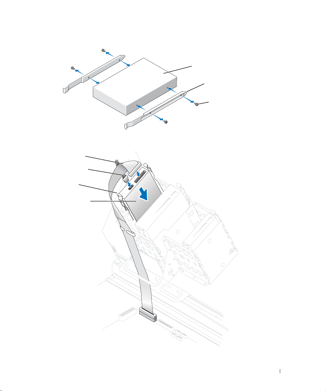
drive
2
Gently slide the drive into place until the tabs securely click into position.
data cable
power cable
tabs (2)
floppy drive
bracket rails (2)
screws (4)
Removing and Installing Parts 91
Page 92

3
Attach the power and data cables to the floppy drive.
4
Connect the other end of the data cable to the connector labled FLOPPY on the system
board (see page 69).
5
Check all cable connections, and fold cables out of the way to provide airflow for the fan and
cooling vents.
6
Close the computer cover (see page 108).
NOTICE: To connect a network cable, first plug the cable into the network wall jack and then plug it into
the computer.
Connect your computer and devices to electrical outlets, and turn them on.
7
See the documentation that came with the drive for instructions on installing any software
www.dell.com | support.dell.com
required for drive operation.
8
Enter system setup (see page 113) and update the appropriate
9
Verify that your computer works correctly by running the Dell Diagnostics (see page 50).
CD/DVD Drive
CAUTION: Before you begin any of the procedures in this section, follow the safety instructions
located in the Product Information Guide.
CAUTION: To guard against electrical shock, always unplug your computer from the electrical outlet
before opening the cover.
Diskette Drive
option.
Removing a CD/DVD Drive
1
Follow the procedures in "Before You Begin" on page 61.
2
Disconnect the power and data cables from the back of the drive.
92 Removing and Installing Parts
Page 93

power cable
tabs (2)
data cable
CD/DVD drive
3
Press inward on the two tabs on the sides of the drive, and then slide the drive upward and
remove it from the drive bay.
Installing a CD/DVD Drive
1
If you are installing a new drive, unpack the drive and prepare it for installation.
Check the documentation that accompanied the drive to verify that the drive is configured
for your computer. If you are installing an IDE drive, configure the drive for the cable select
setting.
2
Connect the new drive to the set of rails that are attached to the inside of the cover. If a set of
rails is not attached inside the computer cover, call Dell (see page 121).
Removing and Installing Parts 93
Page 94
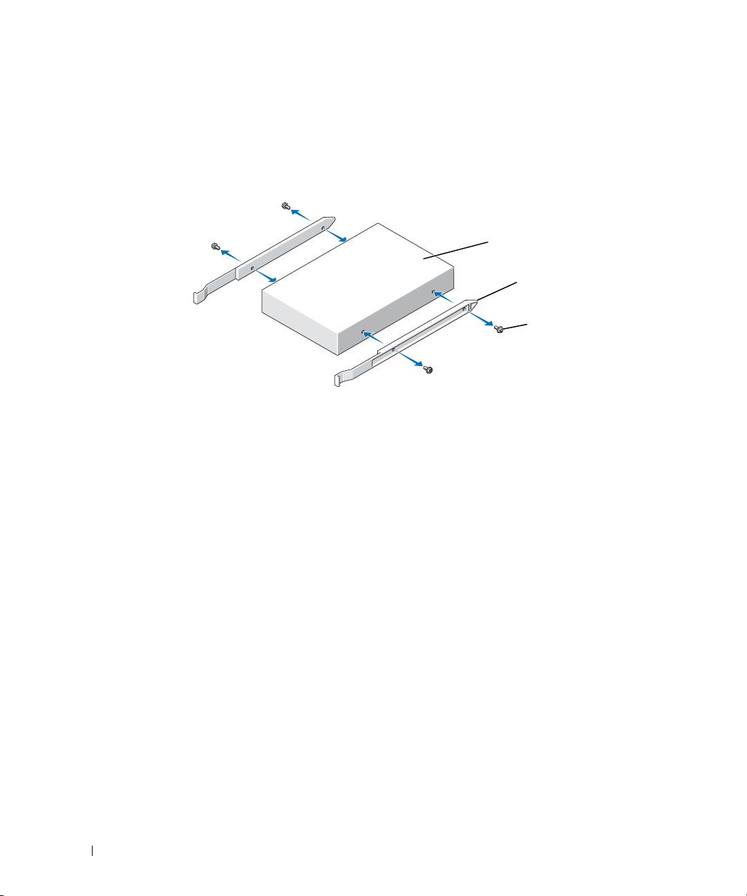
3
If you are installing a replacement drive and the new drive does not have the bracket rails
attached, remove the rails from the old drive by removing the two screws that secure each rail
to the drive. Attach the bracket to the new drive by aligning the screw holes on the drive with
the screw holes on the bracket rails and then inserting and tightening all four screws (two
screws on each rail).
www.dell.com | support.dell.com
4
Gently slide the drive into place until the tabs securely click into position.
5
Connect the power and data cables to the drive.
If you are adding a drive that has an audio cable, connect the audio cable to the audio
connector on the system board.
drive
bracket rails (2)
screws (4)
94 Removing and Installing Parts
Page 95

power cable
tabs (2)
data cable
CD/DVD drive
6
Check all cable connections, and fold cables out of the way to provide airflow for the fan and
cooling vents.
7
Close the computer cover (see page 108).
NOTICE: To connect a network cable, first plug the cable into the network wall jack and then plug it into
the computer.
Connect your computer and devices to electrical outlets, and turn them on.
8
See the documentation that came with the drive for instructions on installing any software
required for drive operation.
9
Enter system setup (see page 69) and select the appropriate
10
Verify that your computer works correctly by running the Dell Diagnostics (see page 50).
Drive
option.
Removing and Installing Parts 95
Page 96

Processor Airflow Shroud
Removing the Processor Airflow Shroud
CAUTION: Before you perform this procedure, follow the safety instructions located in the Product
Information Guide.
CAUTION: To prevent static damage to components inside your computer, discharge static electricity
from your body before you touch any of your computer’s electronic components. You can do so by
touching an unpainted metal surface on the computer chassis.
NOTICE: To avoid damaging the fan power cables, do not slide the shroud too quickly.
Follow the procedures in "Before You Begin" on page 61.
1
www.dell.com | support.dell.com
2
Press the shroud release lever towards the front of the computer.
3
Lift the shroud up to disengage the anchors.
4
Once the shroud has been disengaged from the anchors, unplug the fan cables from their
connectors on the system board.
anchor tabs (3)
shroud release lever
96 Removing and Installing Parts
Page 97

Installing the Processor Airflow Shroud
1
Attach both fan power cables to the connectors on the system board.
2
Align the anchor tabs with the securing slots.
3
Gently press the shroud until the anchor tabs snap securely into place.
4
Close the computer cover.
NOTICE: To connect a network cable, first plug the cable into the network wall jack and then plug it into
the computer.
Connect your computer and devices to electrical outlets, and turn them on.
5
Processor
Removing the Processor
NOTICE:
Do not perform the following steps unless you are familiar with hardware removal
and replacement. Performing these steps incorrectly could damage your system board. For
technical service, see
CAUTION: Before you begin any of the procedures in this section, follow the safety instructions
located in the Product Information Guide.
Follow the procedures in "Before You Begin" on page 61.
1
2
Disconnect the cooling fan power cable from the REAR FAN1 connector (see "System Board
"Contacting Dell" on page 121.
Components" on page 69) on the system board.
3
Disconnect the power cable from the 12V PWR connector (see "System Board Components"
on page 69) on the system board.
4
Lift up the airflow shroud.
Removing and Installing Parts 97
Page 98
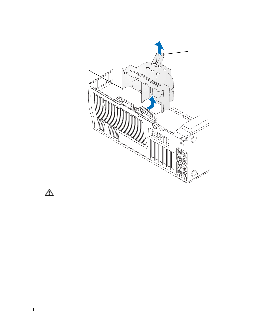
anchor tabs (3)
www.dell.com | support.dell.com
CAUTION: The heat sink can get very hot during normal operation. Be sure that the heat sink has had
sufficient time to cool before you touch it.
Remove the heat sink:
5
a
Remove the retention module clips. Press the tabs toward the center of the clip and
lift up.
shroud release lever
98 Removing and Installing Parts
Page 99

b
On the retention base locate the
tab opposite the power supply.
Press on the retention base tab
until the heat sink pops up
slightly.
c
Press out on the second retention
tab while lifting the heat sink up
and out of the retention base.
NOTICE: Lay the heat sink down on its
side.
NOTICE: If you are installing a processor
upgrade kit from Dell, discard the original
heat sink. If you are not installing a
processor upgrade kit from Dell, reuse the
original heat sink and blower when you
install your new processor.
Push down and out on the socket
6
release lever.
7
Open the processor cover.
heat sink
retention tab
retention base
Removing and Installing Parts 99
Page 100
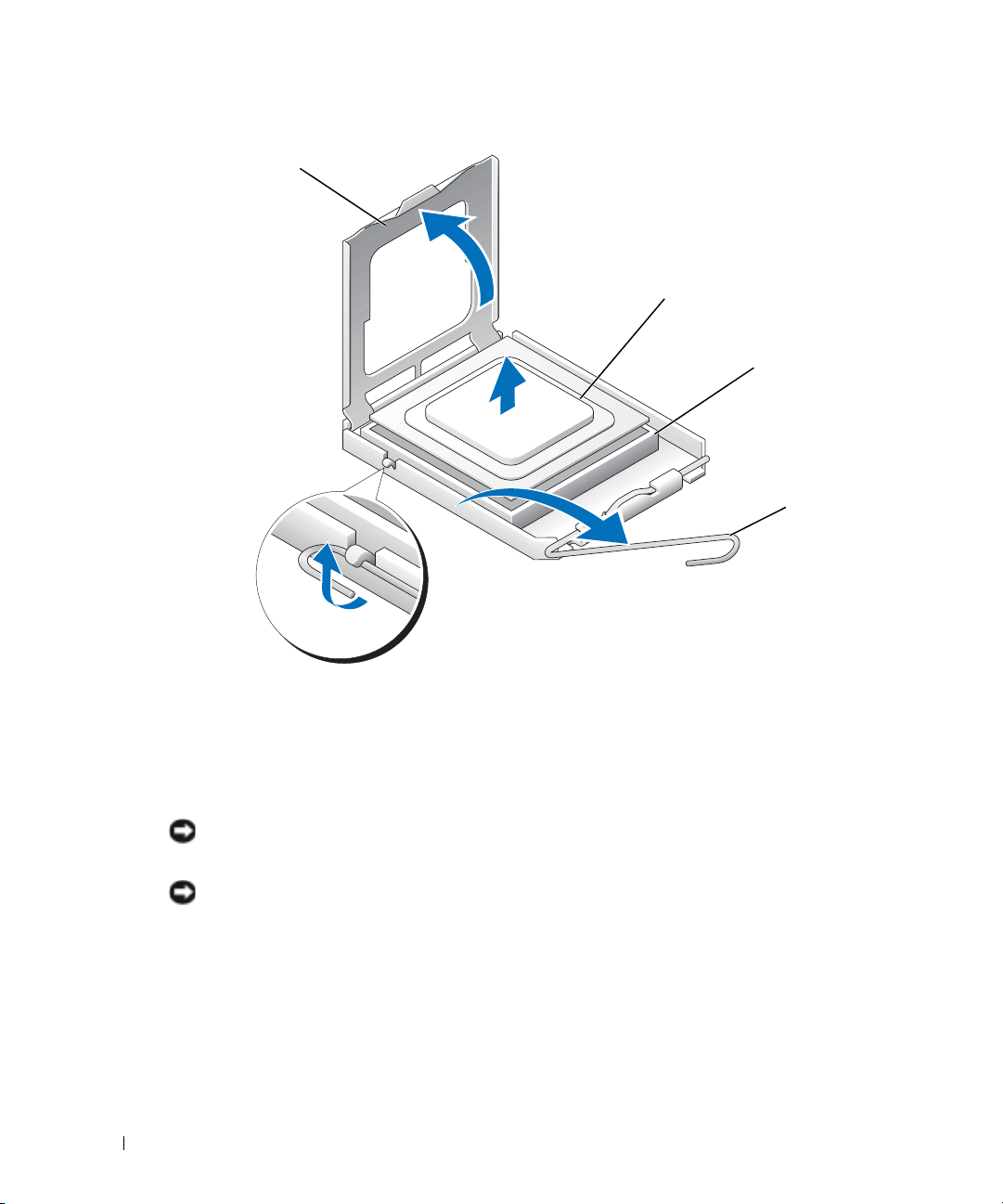
processor cover
www.dell.com | support.dell.com
8
Remove the processor from the socket.
Leave the release lever extended in the release position so that the socket is ready for the new
processor.
processor
socket
release lever
Installing the Processor
NOTICE: Ground yourself by touching an unpainted metal surface on the back of the computer.
Unpack the new processor.
1
NOTICE: You must position the processor correctly in the socket to avoid permanent damage to the
processor and the computer when you turn on the computer.
If the release lever on the socket is not fully extended, move it to that position.
2
3
Align the pin-1 corners of the processor and socket.
100 Removing and Installing Parts
 Loading...