

Page 1

XPS 8910
Service Manual
Computer Model: XPS 8910
Regulatory Model: D24M
Regulatory Type: D24M001
Page 2
Notes, cautions, and warnings
NOTE: A NOTE indicates important information that helps you make
better use of your product.
CAUTION: A CAUTION indicates either potential damage to hardware or
loss of data and tells you how to avoid the problem.
WARNING: A WARNING indicates a potential for property damage,
personal injury, or death.
Copyright © 2017 Dell Inc. or its subsidiaries. All rights reserved. Dell, EMC, and other
trademarks are trademarks of Dell Inc. or its subsidiaries. Other trademarks may be
trademarks of their respective owners.
2017 - 02
Rev. A01
Page 3

Contents
Before working inside your computer........................... 10
Before you begin .....................................................................................10
Safety instructions...................................................................................10
Recommended tools.................................................................................11
Screw list................................................................................................. 12
After working inside your computer..............................14
Technical overview....................................................... 15
Inside view of your computer...................................................................16
System-board components...................................................................... 17
Removing the right-side cover......................................19
Procedure................................................................................................19
Replacing the right-side cover......................................21
Procedure................................................................................................22
Removing the top cover............................................... 24
Prerequisites............................................................................................24
Procedure................................................................................................24
Replacing the top cover...............................................26
Procedure............................................................................................... 26
Post-requisites........................................................................................ 26
3
Page 4

Removing the bottom cover......................................... 27
Prerequisites............................................................................................27
Procedure................................................................................................27
Replacing the bottom cover.........................................29
Procedure............................................................................................... 29
Post-requisites........................................................................................ 29
Removing the front bezel ............................................30
Prerequisites........................................................................................... 30
Procedure................................................................................................ 31
Replacing the front bezel............................................. 33
Procedure................................................................................................33
Post-requisites........................................................................................ 33
Removing the primary hard-drive.................................34
Prerequisites............................................................................................34
Procedure (with tabs)............................................................................. 34
Replacing the primary hard-drive ................................ 37
Procedure (with tabs)..............................................................................37
Post-requisites.........................................................................................37
Removing the primary hard-drive.................................38
Prerequisites............................................................................................38
Procedure (with screws).........................................................................38
Replacing the primary hard-drive ................................42
Procedure................................................................................................42
Post-requisites........................................................................................ 42
4
Page 5

Removing the secondary hard-drive.............................43
Prerequisites............................................................................................43
Procedure................................................................................................43
Replacing the secondary hard-drive.............................47
Post-requisites........................................................................................ 47
Procedure................................................................................................47
Removing the solid-state drive.....................................48
Prerequisites............................................................................................48
Procedure............................................................................................... 48
Replacing the solid-state drive.....................................50
Procedure............................................................................................... 50
Post-requisites........................................................................................ 52
Removing the power-supply unit..................................53
Prerequisites........................................................................................... 53
Procedure............................................................................................... 53
Replacing the power-supply unit.................................. 57
Procedure................................................................................................57
Post-requisites........................................................................................ 58
Removing the coin-cell battery.................................... 59
Prerequisites........................................................................................... 59
Procedure............................................................................................... 59
Replacing the coin-cell battery.....................................61
Procedure................................................................................................61
Post-requisites......................................................................................... 61
5
Page 6

Removing the chassis fan............................................ 62
Prerequisites........................................................................................... 62
Procedure............................................................................................... 62
Replacing the chassis fan............................................ 65
Procedure............................................................................................... 65
Post-requisites........................................................................................ 66
Removing the graphics card.........................................67
Prerequisites............................................................................................67
Procedure................................................................................................67
Replacing the graphics card.........................................69
Procedure............................................................................................... 69
Post-requisites........................................................................................ 69
Removing the full-length graphics cards...................... 70
Prerequisites............................................................................................70
Procedure................................................................................................ 71
Replacing the full-length graphics cards...................... 73
Procedure................................................................................................73
Post-requisites........................................................................................ 73
Removing the memory modules................................... 74
Prerequisites............................................................................................ 74
Procedure................................................................................................74
Replacing the memory modules................................... 76
Procedure................................................................................................76
Post-requisites........................................................................................ 78
6
Page 7

Removing the optical drive...........................................79
Prerequisites ...........................................................................................79
Procedure................................................................................................79
Replacing the optical drive...........................................83
Procedure............................................................................................... 83
Post-requisites.................................................................................. 83
Removing the power-button module............................ 84
Prerequisites............................................................................................84
Procedure............................................................................................... 84
Replacing the power-button module............................ 86
Procedure............................................................................................... 86
Post-requisites........................................................................................ 86
Removing the top I/O-panel.........................................87
Prerequisites............................................................................................87
Procedure................................................................................................87
Replacing the top I/O-panel.........................................90
Procedure............................................................................................... 90
Post-requisites........................................................................................ 90
Removing blower and heat-sink assembly.....................91
Prerequisites............................................................................................ 91
Procedure................................................................................................91
Replacing blower and heat-sink assembly.................... 95
Procedure............................................................................................... 95
Post-requisites........................................................................................ 96
7
Page 8

Removing the processor fan and heat-sink assembly... 97
Prerequisites............................................................................................97
Procedure................................................................................................97
Replacing the processor fan and heat-sink assembly... 99
Procedure............................................................................................... 99
Post-requisites........................................................................................ 99
Removing the processor............................................. 101
Prerequisites...........................................................................................101
Procedure...............................................................................................101
Replacing the processor............................................. 103
Procedure..............................................................................................103
Post-requisites.......................................................................................105
Removing the wireless card........................................106
Prerequisites.......................................................................................... 106
Procedure..............................................................................................106
Replacing the wireless card........................................ 108
Procedure..............................................................................................108
Post-requisites.......................................................................................109
Removing the antenna................................................ 110
Prerequisites...........................................................................................110
Procedure...............................................................................................110
Replacing the antenna.................................................113
Procedure...............................................................................................113
Post-requisites........................................................................................113
8
Page 9

Removing the system board........................................ 114
Prerequisites...........................................................................................114
Procedure...............................................................................................115
Replacing the system board........................................ 116
Procedure...............................................................................................116
Post-requisites........................................................................................116
Flashing the BIOS....................................................... 118
BIOS setup program....................................................119
BIOS overview........................................................................................119
Entering BIOS setup program................................................................. 119
System Setup Options...........................................................................120
Clearing forgotten passwords................................................................ 125
Prerequisites.................................................................................... 125
Procedure........................................................................................125
Post-requisites.................................................................................128
Clearing CMOS settings........................................................................ 128
Prerequisites.................................................................................... 128
Procedure........................................................................................128
Post-requisites.................................................................................130
Diagnostics................................................................. 131
Getting help and contacting Dell.................................132
Self-help resources................................................................................ 132
Contacting Dell...................................................................................... 133
9
Page 10
GUID-5D3B1051-9384-409A-8D5B-9B53BD496DE8
Before working inside your computer
NOTE: The images in this document may dier from your computer
depending on the conguration you ordered.
GUID-D1AE8571-3E47-4D09-AD7C-6AB2F8F0541F
Before you begin
1 Save and close all open les and exit all open applications.
2 Shut down your computer. Click Start → Power → Shut down.
NOTE: If you are using a dierent operating system, see the
documentation of your operating system for shut-down instructions.
3 Disconnect your computer and all attached devices from their electrical outlets.
4 Disconnect all attached network devices and peripherals, such as keyboard,
mouse, and monitor from your computer.
5 Remove any media card and optical disc from your computer, if applicable.
6 After the computer is unplugged, press and hold the power button for 5 seconds
to ground the system board.
GUID-71128823-CE64-4E17-9439-DEE95AF668C4
Safety instructions
Use the following safety guidelines to protect your computer from potential damage
and ensure your personal safety.
WARNING: Before working inside your computer, read the safety
information that shipped with your computer. For more safety best
practices, see the Regulatory Compliance home page at www.dell.com/
regulatory_compliance.
10
Page 11
WARNING: Disconnect all power sources before opening the computer
cover or panels. After you nish working inside the computer, replace all
covers, panels, and screws before connecting to the electrical outlet.
CAUTION: To avoid damaging the computer, ensure that the work surface is
at and clean.
CAUTION: To avoid damaging the components and cards, handle them by
their edges, and avoid touching pins and contacts.
CAUTION: You should only perform troubleshooting and repairs as
authorized or directed by the Dell technical assistance team. Damage due to
servicing that is not authorized by Dell is not covered by your warranty. See
the safety instructions that shipped with the product or at www.dell.com/
regulatory_compliance.
CAUTION: Before touching anything inside your computer, ground yourself
by touching an unpainted metal surface, such as the metal at the back of
the computer. While you work, periodically touch an unpainted metal surface
to dissipate static electricity, which could harm internal components.
CAUTION: When you disconnect a cable, pull on its connector or on its pull
tab, not on the cable itself. Some cables have connectors with locking tabs
or thumb-screws that you must disengage before disconnecting the cable.
When disconnecting cables, keep them evenly aligned to avoid bending any
connector pins. When connecting cables, ensure that the ports and
connectors are correctly oriented and aligned.
CAUTION: Press and eject any installed card from the media-card reader.
GUID-6F9394C5-085D-4E07-924F-D3EA18F0757A
Recommended tools
The procedures in this document may require the following tools:
• Philips screwdriver
• Flat-head screwdriver
• Plastic scribe
11
Page 12
GUID-FA888C3D-2FA8-479D-98DB-D7B3F27035D7
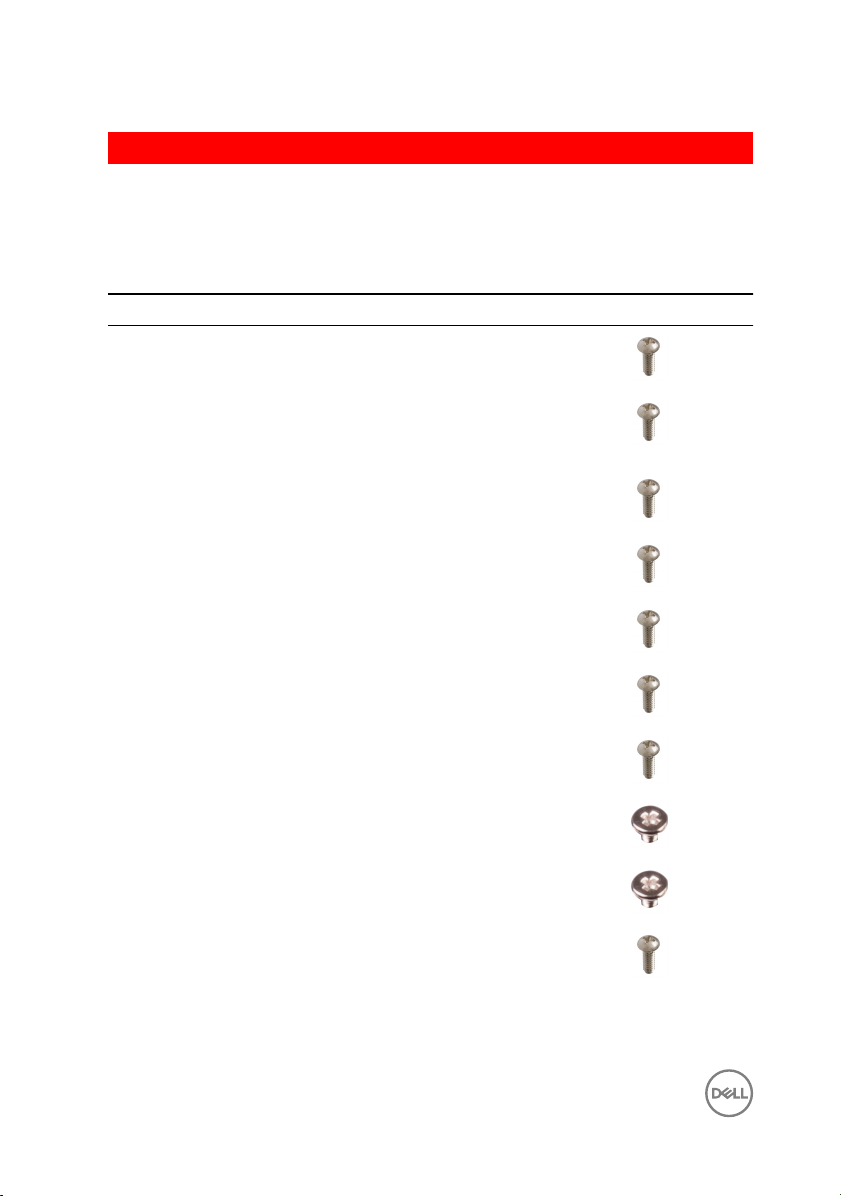
Screw list
The following table provides the list of screws that are used for securing dierent
components to the computer.
Table 1. Screw list
Component Secured to Screw type Quantity Screw image
Hard drive Hard-drive
bracket
#6-32x1/4'' 4
Hard-drive
cage
Power-supply
bracket
Power-supply
unit
Blower Heat-sink
Chassis fan Chassis #6-32x1/4'' 1
Power button
module
Solid-state
drive
Wireless card System board M2x2.5 1
Top IO panel Chassis #6-32x1/4'' 4
Chassis #6-32x1/4'' 6 (two per
Chassis #6-32x1/4'' 2
Chassis #6-32x1/4'' 4
#6-32x1/4'' 3
assembly
Top panel #6-32x1/4'' 1
System board M2x2.5 1
hard-drive
cage installed)
12
Page 13
Component Secured to Screw type Quantity Screw image
ODD ODD bracket M2x2.5 1
System board Chassis #6-32x1/4'' 8
13
Page 14

GUID-06588814-2678-4667-9FF9-C009F4BCE185
After working inside your computer
CAUTION: Leaving stray or loose screws inside your computer may severely
damage your computer.
1 Replace all screws and ensure that no stray screws remain inside your computer.
2 Connect any external devices, peripherals, or cables you removed before working
on your computer.
3 Replace any media cards, discs, or any other parts that you removed before
working on your computer.
4 Connect your computer and all attached devices to their electrical outlets.
5 Turn on your computer.
14
Page 15

GUID-93575C2B-9DA3-42EF-B01E-9C841B3CE7F5
Technical overview
WARNING: Before working inside your computer, read the safety
information that shipped with your computer and follow the steps in Before
working inside your computer. After working inside your computer, follow
the instructions in After working inside your computer. For more safety best
practices, see the Regulatory Compliance home page at
regulatory_compliance.
www.dell.com/
15
Page 16
GUID-448B3EEF-B478-4D2D-A745-D7DA94EB263E
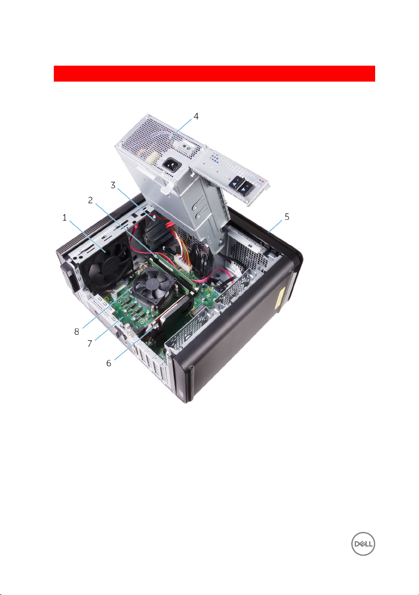
Inside view of your computer
1 chassis fan 2 memory module
3 optical drive 4 power-supply unit
5 front bezel 6 graphics card
7 system board 8 processor fan and heat-sink
16
assembly
Page 17
GUID-09138897-CBE9-49C8-B4BA-9882357209CF
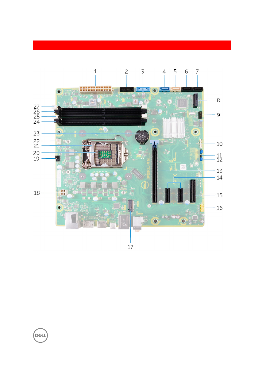
System-board components
1 system board power connector
(ATX_POWER)
3 USB 1 (F_SSUSB1) 4 SATA 6 Gbps for hard drive
5 SATA 6 Gbps for optical drive
(SATA2)
7 SATA 6 Gbps drive connector
(SATA4)
2 USB 2 (F_SSUSB2)
(SATA1)
6 SATA 6 Gbps drive connector
(SATA3)
8 solid-state drive slot (M.2 SSD)
17
Page 18

9 front I/O panel (F_PANEL) 10 media card reader connector
11 CMOS-reset jumper (CMOS
JUMPER)
13 PCI-Express x16 card slot (SLOT1) 14 PCI-Express x1 card slots (SLOT 2
15 PCI-Express x4 card slot (SLOT 4) 16 front audio connector (F_audio)
17 wireless-card slot (M.2_SLOT1) 18 CPU power cable (ATX_CPU)
19 chassis-fan connector (TOP_FAN) 20 processor socket
21 processor release latch 22 processor-fan connector
23 coin-cell battery (CMOS BATTERY) 24 memory-module slot (DIMM3)
25 memory-module slot (DIMM1) 26 memory-module slot (DIMM4)
27 memory-module slot (DIMM2)
(CARD_READER)
12 password-reset jumper
(PASSWORD JUMPER)
and SLOT 3)
(CPU_FAN)
18
Page 19
GUID-32920A3D-EF37-460E-B64C-7149A8013426
Removing the right-side cover
WARNING: Before working inside your computer, read the safety
information that shipped with your computer and follow the steps in Before
working inside your computer. After working inside your computer, follow
the instructions in After working inside your computer. For more safety best
practices, see the Regulatory Compliance home page at
regulatory_compliance.
GUID-EDCF1D0A-9913-4F7C-B653-5FE8FC6F3908
Procedure
1 Lay the computer on the left side.
2 Pull the right-side cover release latch.
3 Lift the right-side cover and then slide it towards the top of the computer.
www.dell.com/
19
Page 20
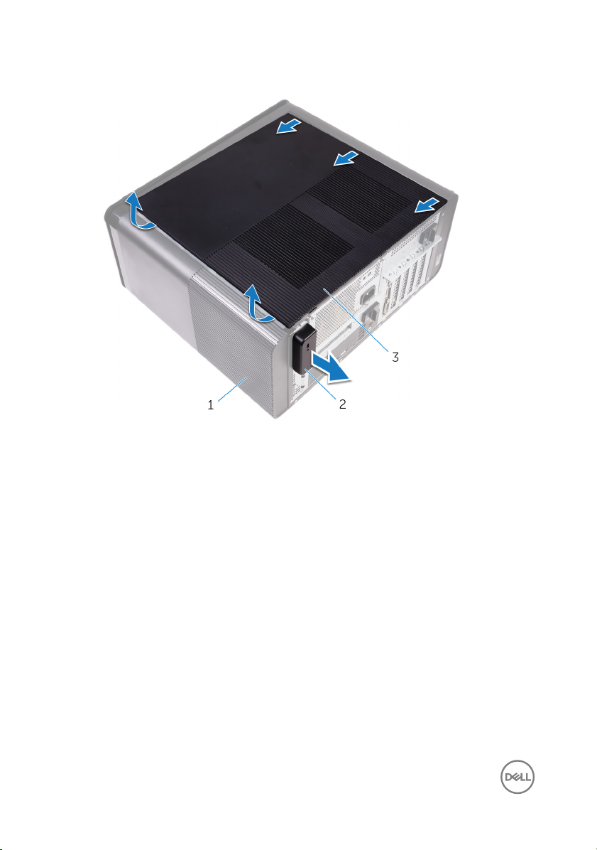
4 Remove the right-side cover from the chassis.
Figure 1. Removing the right-side cover
1 chassis 2 right-side cover release latch
3 right-side cover
20
Page 21
GUID-1C3945D8-E66C-4259-9384-C8C7E07F7495
Replacing the right-side cover
WARNING: Before working inside your computer, read the safety
information that shipped with your computer and follow the steps in Before
working inside your computer. After working inside your computer, follow
the instructions in After working inside your computer. For more safety best
practices, see the Regulatory Compliance home page at
regulatory_compliance.
www.dell.com/
21
Page 22

GUID-D9051F2F-09D0-4AEC-8F3C-D6B5EA9F14D1
Procedure
1 Align the tabs on the right-side cover with the slots on the chassis and snap the
side-cover to lock it in place.
Figure 2. Right-side cover replacement
1
slots 2 tabs
3 chassis 4 right-side cover
22
Page 23

2 Place the computer in an upright position.
23
Page 24

GUID-3F6153AE-D9C1-4062-B211-E93EC9AE091F
Removing the top cover
WARNING: Before working inside your computer, read the safety
information that shipped with your computer and follow the steps in Before
working inside your computer. After working inside your computer, follow
the instructions in After working inside your computer. For more safety best
practices, see the Regulatory Compliance home page at
regulatory_compliance.
GUID-D6090253-6EAF-4672-A7FA-5772B9885A3E
Prerequisites
Remove the right-side cover.
GUID-99ED113A-2093-499A-AC10-70C0AE9305C0
Procedure
1 Place the computer in an upright position.
www.dell.com/
24
Page 25
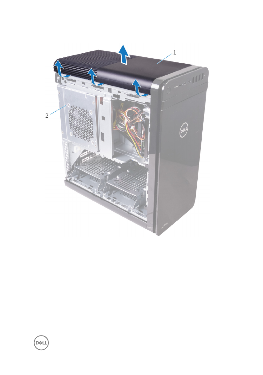
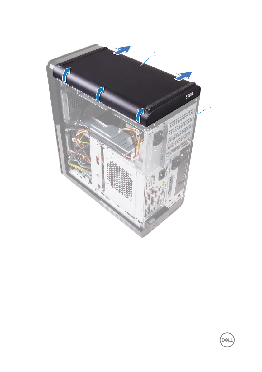
2 Pry the cover from the back corner and lift the top cover away from the chassis.
Figure 3. Removing the top cover
1
top cover 2 chassis
25
Page 26
GUID-8C492B5B-B5ED-4E67-9666-D18E8041AFFB
Replacing the top cover
WARNING: Before working inside your computer, read the safety
information that shipped with your computer and follow the steps in Before
working inside your computer. After working inside your computer, follow
the instructions in After working inside your computer. For more safety best
practices, see the Regulatory Compliance home page at
regulatory_compliance.
GUID-20FD4DCE-22FD-4D36-A59C-804C06543E0B
Procedure
Align the tabs on the top cover with the slots on the top panel and press the top
cover until it snaps into place.
GUID-750C172E-A9F2-4AD2-B7EA-6144194DC8B1
Post-requisites
Replace the right-side cover.
www.dell.com/
26
Page 27
GUID-2EEB123D-D085-4BE8-994B-0F693D55ECE8
Removing the bottom cover
WARNING: Before working inside your computer, read the safety
information that shipped with your computer and follow the steps in Before
working inside your computer. After working inside your computer, follow
the instructions in After working inside your computer. For more safety best
practices, see the Regulatory Compliance home page at
regulatory_compliance.
GUID-D6090253-6EAF-4672-A7FA-5772B9885A3E
Prerequisites
Remove the right-side cover.
GUID-A7F130BF-BA39-4D40-94AF-869F970C0311
Procedure
1 Place the computer with the bottom facing up.
www.dell.com/
27
Page 28
2 Pry and lift the bottom cover away from the chassis.
Figure 4. Removing the bottom cover
1
bottom cover 2 chassis
28
Page 29
GUID-482EB960-4B34-4F58-8F2B-9B766EF21AB3
Replacing the bottom cover
WARNING: Before working inside your computer, read the safety
information that shipped with your computer and follow the steps in Before
working inside your computer. After working inside your computer, follow
the instructions in After working inside your computer. For more safety best
practices, see the Regulatory Compliance home page at
regulatory_compliance.
GUID-D7BC349D-87D5-4DC0-959A-8DDC3020128C
Procedure
Align the tabs on the bottom cover with the slots on the bottom panel and press
the bottom cover until it snaps in place.
GUID-750C172E-A9F2-4AD2-B7EA-6144194DC8B1
Post-requisites
Replace the right-side cover.
www.dell.com/
29
Page 30
GUID-E782B6FD-6208-4460-8AD1-2CF3F3D81247
Removing the front bezel
WARNING: Before working inside your computer, read the safety
information that shipped with your computer and follow the steps in Before
working inside your computer. After working inside your computer, follow
the instructions in After working inside your computer. For more safety best
practices, see the Regulatory Compliance home page at
regulatory_compliance.
GUID-C1517B50-8FDB-4047-95EA-B96A9ADF371E
Prerequisites
Remove the right-side cover.
www.dell.com/
30
Page 31

GUID-6606D9B7-C45A-46C7-AD35-C782735B4DD4
Procedure
1 Pry the optical-drive bezel from the optical drive.
Figure 5. Removing the optical drive bezel
1
optical-drive bezel 2 front bezel
2 Release the front-bezel tabs sequentially from the top, one at a time by moving
them away from the front chassis.
31
Page 32

3 Rotate and pull the front bezel away from the front of the chassis to release the
front-bezel.
Figure 6. Removing the front bezel
1
front-bezel tabs 2 front bezel
3 front chassis
32
Page 33

GUID-60F23EC0-94F6-45C6-B6CD-17F914DA5206
Replacing the front bezel
WARNING: Before working inside your computer, read the safety
information that shipped with your computer and follow the steps in Before
working inside your computer. After working inside your computer, follow
the instructions in After working inside your computer. For more safety best
practices, see the Regulatory Compliance home page at
regulatory_compliance.
GUID-56C3CE8A-62CC-48B1-A307-6381B7867E44
Procedure
1 Align the tabs on the front bezel with the slots on the chassis.
2 Rotate the front bezel towards the chassis until the front bezel tabs snap into
place.
3 Snap the optical-drive bezel to the optical drive.
GUID-C6F7848F-00D8-4782-9A55-9C2ECBE260C0
Post-requisites
www.dell.com/
Replace the right-side cover.
33
Page 34

GUID-78AC3600-45A1-47C0-81CC-1965860F4FA1
Removing the primary hard-drive
WARNING: Before working inside your computer, read the safety
information that shipped with your computer and follow the steps in Before
working inside your computer. After working inside your computer, follow
the instructions in After working inside your computer. For more safety best
practices, see the Regulatory Compliance home page at
regulatory_compliance.
CAUTION: Hard drives are fragile. Exercise care when handling the hard
drive.
CAUTION: To avoid data loss, do not remove the hard drive while the
computer is in sleep or on state.
GUID-575F0828-77C1-4FB8-B456-BA3DA73884DB
Prerequisites
Remove the right-side cover.
GUID-26CAC413-EFC2-4EBC-B0BA-249938C8F771
Procedure (with tabs)
www.dell.com/
1 Disconnect the data and power cables from the hard-drive.
34
Page 35

2 Press the release tabs on the hard-drive carrier and slide the hard-drive carrier
out of the hard-drive cage.
Figure 7. Removing the hard-drive assembly
1
data cable 2 power cable
3 hard-drive cage 4 release tabs
5 hard-drive carrier
3 Pry the hard-drive carrier to release the tabs on the carrier from the slots on the
hard drive.
35
Page 36

4 Lift the hard drive o the hard-drive carrier.
NOTE: Note the orientation of the hard drive to replace it correctly.
Figure 8. Removing the hard drive from the bracket
1 hard drive 2 hard-drive carrier
3 tabs
36
Page 37

GUID-80BE1924-1F75-43E6-B673-9BCBCBB26DA0
Replacing the primary hard-drive
WARNING: Before working inside your computer, read the safety
information that shipped with your computer and follow the steps in Before
working inside your computer. After working inside your computer, follow
the instructions in After working inside your computer. For more safety best
practices, see the Regulatory Compliance home page at
regulatory_compliance.
CAUTION: Hard drives are fragile. Exercise care when handling the hard
drive.
GUID-72A6FE31-4285-491F-A242-8E71FDEAAD14
Procedure (with tabs)
1 Place the hard drive into the hard-drive carrier and align the tabs on the bracket
with the slots on the hard drive.
2 Snap the hard-drive carrier into the hard drive.
3 Slide the hard-drive carrier into the hard-drive cage until it snaps into place.
4 Connect the data and power cables to the hard-drive.
www.dell.com/
GUID-D64D31F4-66C5-46A8-A059-0B0B3626DF49
Post-requisites
Replace the right-side cover.
37
Page 38

GUID-78AC3600-45A1-47C0-81CC-1965860F4FA1
Removing the primary hard-drive
WARNING: Before working inside your computer, read the safety
information that shipped with your computer and follow the steps in Before
working inside your computer. After working inside your computer, follow
the instructions in After working inside your computer. For more safety best
practices, see the Regulatory Compliance home page at
regulatory_compliance.
CAUTION: Hard drives are fragile. Exercise care when handling the hard
drive.
CAUTION: To avoid data loss, do not remove the hard drive while the
computer is in sleep or on state.
GUID-575F0828-77C1-4FB8-B456-BA3DA73884DB
Prerequisites
Remove the right-side cover.
GUID-A6E4604E-7DA9-4B0F-BA1E-BBEDAA74E737
Procedure (with screws)
www.dell.com/
NOTE: There is a running change on implementing a new blue tool-less
plastic bracket for the primary hard-disk drive. Technicians encounter that
later revisions of the systems have the new blue tool-less plastic bracket for
the primary hard-disk drive.
1 Disconnect the data and power cables from the hard drive.
38
Page 39

2 Remove the screws that secure the hard-drive cage to the chassis.
Figure 9. Disconnecting cables
1
#6-32x1/4'' screws (2) 2 hard drive
3 hard-drive cage 4 data cable
5 power cable
39
Page 40

3 Lift the hard-drive cage o the chassis.
Figure 10. Removing the hard-drive cage
1 hard-drive cage 2 tab
3 hard-drive assembly
4 Remove the screws that secure the hard drive to the hard-drive cage.
40
Page 41

5 Lift the hard drive o the hard-drive cage.
NOTE: Note the orientation of the hard drive to replace it correctly.
Figure 11. Removing the hard drive from the bracket
1
#6-32 X 1/4'' screws (4) 2 hard drive
3 hard-drive cage
41
Page 42

GUID-80BE1924-1F75-43E6-B673-9BCBCBB26DA0
Replacing the primary hard-drive
WARNING: Before working inside your computer, read the safety
information that shipped with your computer and follow the steps in Before
working inside your computer. After working inside your computer, follow
the instructions in After working inside your computer. For more safety best
practices, see the Regulatory Compliance home page at
regulatory_compliance.
CAUTION: Hard drives are fragile. Exercise care when handling the hard
drive.
GUID-5F95CF58-74DB-4DE5-9E4C-B3924638380E
Procedure
1 Place the hard drive into the hard-drive cage.
2 Align the screw holes on the hard-drive cage with the screw holes on the hard
drive.
3 Replace the screws that secure the hard drive to the hard-drive cage.
4 Insert the hard-drive cage into the chassis.
5 Replace the screws that secure the hard-drive cage to the chassis.
6 Connect the data and power cables to the hard drive.
www.dell.com/
GUID-D64D31F4-66C5-46A8-A059-0B0B3626DF49
Post-requisites
Replace the right-side cover.
42
Page 43

GUID-A18ABCD1-5BB5-454A-AEB8-5615E4179436
Removing the secondary harddrive
WARNING: Before working inside your computer, read the safety
information that shipped with your computer and follow the steps in Before
working inside your computer. After working inside your computer, follow
the instructions in After working inside your computer. For more safety best
practices, see the Regulatory Compliance home page at www.dell.com/
regulatory_compliance.
CAUTION: Hard drives are fragile. Exercise care when handling the hard
drive.
CAUTION: To avoid data loss, do not remove the hard drive while the
computer is in sleep or on state.
GUID-575F0828-77C1-4FB8-B456-BA3DA73884DB
Prerequisites
Remove the right-side cover.
GUID-3E09CC2F-6E91-4D5E-9D55-DD0A024D1669
Procedure
1 Disconnect the data and power cables from the hard drive.
43
Page 44

2 Remove the screws that secure the hard-drive cage to chassis.
1 #6-32 X 1/4'' screws (2) 2 hard drive
3 hard-drive cage 4 power cable
5 data cable
44
Page 45

3 Lift the hard drive cage o the chassis.
1 hard drive 2 hard-drive cage
4 Remove the screws that secure the hard drive to the hard-drive cage.
45
Page 46

5 Lift the hard drive out of the hard drive cage.
NOTE: Note the orientation of the hard drive so that you can replace it
correctly.
1 #6-32 X 1/4'' screws (4) 2 hard drive
3 hard-drive cage
46
Page 47

GUID-D5BB61C4-423E-4C17-967B-952CA5506A1F
Replacing the secondary harddrive
WARNING: Before working inside your computer, read the safety
information that shipped with your computer and follow the steps in Before
working inside your computer. After working inside your computer, follow
the instructions in After working inside your computer. For more safety best
practices, see the Regulatory Compliance home page at www.dell.com/
regulatory_compliance.
CAUTION: Hard drives are fragile. Exercise care when handling the hard
drive.
GUID-D64D31F4-66C5-46A8-A059-0B0B3626DF49
Post-requisites
Replace the right-side cover.
GUID-EA008414-1045-4F17-BC68-8E30BE3073E1
Procedure
1 Place the hard drive into the hard-drive cage.
2 Replace the screws that secure the hard drive to the hard-drive cage.
3 Place the hard-drive cage into the hard-drive cage slot in the chassis.
4 Replace the screws that secure the hard-drive cage to the chassis.
5 Connect the data and power cables to the hard drive.
47
Page 48

GUID-1C25F362-25CF-40CD-8A9B-2B98FB94F5FC
Removing the solid-state drive
WARNING: Before working inside your computer, read the safety
information that shipped with your computer and follow the steps in Before
working inside your computer. After working inside your computer, follow
the instructions in After working inside your computer. For more safety best
practices, see the Regulatory Compliance home page at
regulatory_compliance.
CAUTION: Solid-state drives are fragile. Exercise care when handling the
solid-state drive.
CAUTION: To avoid data loss, do not remove the solid-state drive while the
computer is in sleep or on state.
GUID-8B2299D1-0783-4006-AE74-48B3B0B4C820
Prerequisites
1 Remove the right-side cover.
2 Remove the full-length graphics card (if installed).
GUID-5BDA453A-8318-4B25-B57B-F3C29469AFA0
www.dell.com/
Procedure
1 Remove the screw that secures the solid-state drive to the system board.
48
Page 49

2 Slide and lift the solid-state drive o the system board.
For more information, see “System-board components”.
Figure 12. Removing the solid-state drive
1
solid-state drive 2 solid-state drive slot
3 system board 4 M2x2.5 screw
49
Page 50

GUID-792E5316-8EFA-4894-AE68-995416D3FD47
Replacing the solid-state drive
WARNING: Before working inside your computer, read the safety
information that shipped with your computer and follow the steps in Before
working inside your computer. After working inside your computer, follow
the instructions in After working inside your computer. For more safety best
practices, see the Regulatory Compliance home page at
regulatory_compliance.
CAUTION: Solid-state drives are fragile. Exercise care when handling the
solid-state drive.
GUID-3817BDD4-E065-4B7C-B93F-2A9B2CFFB72B
Procedure
1 Align the notch on the solid-state drive with the tab on the solid-state drive slot.
2 Insert the solid-state drive at a 45-degree angle into the solid-drive drive slot.
For more information, see “System-board components”.
www.dell.com/
50
Page 51

3 Replace the screw that secures the solid-state drive to the system board.
Figure 13. Replacing the solid-state drive
1
tab 2 notch
3 solid-state drive slot 4 solid-state drive
5 system board 6 M2 X 2.5 screw
51
Page 52

GUID-FE898C86-E075-42D9-AAE9-DA973048FC74
Post-requisites
1 Replace the full-length graphics card (if installed).
2 Replace the right-side cover.
52
Page 53

GUID-1F397551-A024-4EA9-8C08-8B7FDE9D50D9
Removing the power-supply unit
WARNING: Before working inside your computer, read the safety
information that shipped with your computer and follow the steps in Before
working inside your computer. After working inside your computer, follow
the instructions in After working inside your computer. For more safety best
practices, see the Regulatory Compliance home page at
regulatory_compliance.
GUID-AA84DB97-E4BF-4D29-8FB7-2EB35ED08CFF
Prerequisites
Remove the right-side cover.
GUID-8EE9E22B-B7AE-4A40-B63D-32BFCE61A578
Procedure
NOTE: Note the routing of all cables as you remove them so that you can
reroute them correctly after you replace the power supply.
1 Slide the power-supply unit cage release latches towards the unlock position.
www.dell.com/
53
Page 54

2 Rotate the power-supply unit cage away from the chassis.
Figure 14. Rotating the power-supply unit
1
power-supply unit cage release
2 power-supply unit
latches (2)
3 chassis 4 power-supply unit cage
3 Disconnect the CPU-power cable and system board power cable from the
system board and the optical-drive power cable from the optical drive.
For more information, see “System-board components”.
4 Disconnect the graphics-card power cables if applicable.
54
Page 55

5 Remove the system-board power cable from the routing guide on the chassis.
Figure 15. Disconnecting cables
1
optical drive power cable 2 routing guide
3 CPU power cable 4 system board
5 system board power cable
6 Rotate the power-supply unit cage towards the chassis.
7 Disconnect the hard-disk power cable.
NOTE: There could be up to three hard-disk power cables depending on
the quantity of hard-disk drive installed.
8 Remove the screws that secure the power-supply bracket to the chassis.
9 Remove the screws that secure the power-supply unit to the chassis.
55
Page 56

10 Lift the power-supply bracket o the chassis.
11 Lift the power-supply unit o the chassis.
Figure 16. Removing the power supply unit
1
#6-32x1/4'' screws (4) 2 power-supply unit
3 power-supply bracket 4 #6-32x1/4'' screws (2)
5 hard-drive cable
56
Page 57

GUID-CCFAEC7A-D969-4E76-B806-44830D484EDD
Replacing the power-supply unit
WARNING: Before working inside your computer, read the safety
information that shipped with your computer and follow the steps in Before
working inside your computer. After working inside your computer, follow
the instructions in After working inside your computer. For more safety best
practices, see the Regulatory Compliance home page at
regulatory_compliance.
GUID-0D86F51D-F211-4C35-96CB-E9313ADEFDA8
Procedure
1 Place the power supply on the power-supply unit cage.
2 Replace the screws that secure the power-supply unit to the power-supply unit
cage.
3 Align the screw holes on the power-supply bracket with the screw holes on the
power-supply unit cage.
4 Replace the screws that secure the power supply bracket to the power-supply
unit cage.
5 Connect the hard-drive power cable.
6 Rotate the power-supply unit away from the chassis.
7 Connect the CPU-power cable, system-board power cable to the system board
and the optical-drive power cable to the optical drive.
For more information, see “System-board components”.
8 Route the system-board power cable through the routing guide on the chassis.
9 Connect the graphics-card power cables if applicable.
10 Rotate the power-supply unit towards the chassis until the unit snaps into place.
11 Slide the power-supply unit cage release latches to their locking positions to lock
the release latches.
www.dell.com/
57
Page 58

GUID-7FD5A030-F5ED-4A45-AEAC-6DCD2E555AC2
Post-requisites
Replace the right-side cover.
58
Page 59

GUID-30EEBC49-DE3E-4C3F-8226-86CE5F32F388
Removing the coin-cell battery
WARNING: Before working inside your computer, read the safety
information that shipped with your computer and follow the steps in Before
working inside your computer. After working inside your computer, follow
the instructions in After working inside your computer. For more safety best
practices, see the Regulatory Compliance home page at
regulatory_compliance.
CAUTION: Removing the coin-cell battery resets the BIOS setup program’s
settings to default. It is recommended that you note the BIOS setup
program’s settings before removing the coin-cell battery.
GUID-5EFF739A-0A1B-40ED-AE49-BD95A99EB77C
Prerequisites
1 Remove the right-side cover.
2 Follow the procedure from step 1 to step 2 in “Removing the power-supply unit”.
GUID-2D8BB1F3-D937-47AD-BDF6-60BA81BCFB8D
Procedure
www.dell.com/
1 Using a plastic scribe, press the battery-release lever away from the coin-cell
battery until the coin-cell battery pops up.
59
Page 60

2 Lift the coin-cell battery out of its socket.
Figure 17. Removing the coin cell battery
1
plastic scribe 2 coin-cell battery
3 coin-cell battery socket 4 battery-release lever
60
Page 61

GUID-5E22F4A0-F01F-4522-8155-BE22A8CA6E5F
Replacing the coin-cell battery
WARNING: Before working inside your computer, read the safety
information that shipped with your computer and follow the steps in Before
working inside your computer. After working inside your computer, follow
the instructions in After working inside your computer. For more safety best
practices, see the Regulatory Compliance home page at
regulatory_compliance.
GUID-A74CC6EE-4F64-49B7-A9E7-79E38AD015D8
Procedure
Insert the coin-cell battery into the battery socket with the positive side facing up,
and snap the battery into place.
GUID-49B6DBB4-5997-4F3E-B6B7-AF1E1147CC22
Post-requisites
1 Follow the procedure from step 9 to step 10 in “Replacing the power-supply
unit”.
2 Replace the right-side cover.
www.dell.com/
61
Page 62

GUID-CF4B7AEA-F9A9-4432-8BD8-AB77D419F494
Removing the chassis fan
WARNING: Before working inside your computer, read the safety
information that shipped with your computer and follow the steps in Before
working inside your computer. After working inside your computer, follow
the instructions in After working inside your computer. For more safety best
practices, see the Regulatory Compliance home page at
regulatory_compliance.
GUID-3DF715A5-7D2F-482F-AD0F-237354999DC7
Prerequisites
1 Remove the right-side cover.
2 Follow the procedure from step 1 to step 2 in “Removing the power-supply unit”.
3 Remove the blower and heat-sink assembly. (if installed)
GUID-3DDE47B6-2DD3-4BDC-8D60-76B221B3A6B9
Procedure
1 Remove the chassis-fan cable from the routing guide on the chassis-fan bracket.
2 Disconnect the chassis-fan cable from the system board.
For more information, see “System-board components”.
3 Remove the screw that secures the chassis-fan bracket to the chassis.
4 Slide the chassis-fan assembly towards the front of the computer to release the
fan from the chassis.
www.dell.com/
62
Page 63

5 Lift the chassis-fan assembly o the chassis.
Figure 18. Removing the chassis fan
1
routing guide 2 chassis-fan bracket
3 #6-32x1/4'' screw 4 chassis
5 chassis-fan cable 6 system board
7 chassis fan
6 Push the rubber grommets through the holes at each corner of the fan to
release the chassis-fan from the bracket.
63
Page 64

7 Lift the chassis-fan o the chassis-fan bracket.
Figure 19. Removing the chassis fan
1 chassis-fan bracket 2 chassis-fan
64
Page 65

GUID-A5935F79-B1C0-4412-A1FD-03EA0DB0E2A1
Replacing the chassis fan
WARNING: Before working inside your computer, read the safety
information that shipped with your computer and follow the steps in Before
working inside your computer. After working inside your computer, follow
the instructions in After working inside your computer. For more safety best
practices, see the Regulatory Compliance home page at
regulatory_compliance.
GUID-0F79EBD5-BE13-4995-AC99-7B0D1F931B0F
Procedure
1 Align the holes on the chassis fan with the rubber grommets on the chassis-fan
bracket.
NOTE: You must correctly align to the chassis-fan bracket to ensure
that the chassis fan is secured to the computer.
2 Insert the ends of the rubber grommets through the holes at each corner of the
fan.
3 Align the grommets in the fan with the holes at each corner of the chassis fan
bracket and pull through until they snap into place.
4 Route the chassis-fan cable through the routing guide on the bracket.
5 Align the tabs on the chassis-fan bracket with the slots on the chassis and slide
the fan into position.
6 Align the screw hole on the chassis-fan bracket with the screw hole on the
chassis.
7 Replace the screw that secures the chassis-fan bracket to the chassis.
8 Route the chassis-fan cable through the routing guide on the bracket.
9 Connect the chassis-fan cable to the system board.
For more information, see “System-board components”.
www.dell.com/
65
Page 66

GUID-5EEC3ED6-B8B5-4C73-9E03-FBDC7B722C1B
Post-requisites
1 Replace the blower and heat-sink assembly. (if installed)
2 Follow the procedure from step 9 to step 10 in “Replacing the power-supply
unit”.
3 Replace the right-side cover.
66
Page 67

GUID-B4F677A5-AC31-4D04-888C-5BEF42FDA20E
Removing the graphics card
WARNING: Before working inside your computer, read the safety
information that shipped with your computer and follow the steps in Before
working inside your computer. After working inside your computer, follow
the instructions in After working inside your computer. For more safety best
practices, see the Regulatory Compliance home page at
regulatory_compliance.
GUID-5DB1479A-F84A-447F-85BE-181D9381E07E
Prerequisites
NOTE: Your computer will be shipped with either graphics card or full-length
graphics card.
1 Remove the right-side cover.
2 Follow the procedure from step 1 to step 2 in “Removing the power-supply unit”.
GUID-FA2E3786-AC82-4452-A398-44ABBB98AE85
Procedure
www.dell.com/
1 Locate the graphics card on the system board and make note of the graphics-
card slot (PCI-Express x16).
For more information, see “System-board components”.
67
Page 68

2 Push the securing tab on the PCIe slot away from the graphics card, grasp the
card by its top corner, and ease it out of the slot.
Figure 20. Removing the graphics card
1
securing tab 2 system board
3 graphics card slot 4 graphics card
68
Page 69

GUID-B39A6E88-5BE8-4905-936B-086878866EBD
Replacing the graphics card
WARNING: Before working inside your computer, read the safety
information that shipped with your computer and follow the steps in Before
working inside your computer. After working inside your computer, follow
the instructions in After working inside your computer. For more safety best
practices, see the Regulatory Compliance home page at
regulatory_compliance.
GUID-813C4CE2-B2A6-44CA-90ED-D1275D3D233E
Procedure
1 Locate the PCI-Express x16 card slot on the system board.
For more information, see “System-board components”.
2 Align the notch on the graphics card with the tab on the slot and snap the
graphics card in place.
GUID-2267DD85-6888-4EFD-A633-20D9C0C6CBA1
Post-requisites
www.dell.com/
1 Follow the procedure from step 9 to step 10 in “Replacing the power-supply
unit”.
2 Replace the right-side cover.
69
Page 70

GUID-C9FD7332-C2FA-42A1-8D1D-DB62492AC771
Removing the full-length graphics cards
WARNING: Before working inside your computer, read the safety
information that shipped with your computer and follow the steps in Before
working inside your computer. After working inside your computer, follow
the instructions in After working inside your computer. For more safety best
practices, see the Regulatory Compliance home page at www.dell.com/
regulatory_compliance.
GUID-5DB1479A-F84A-447F-85BE-181D9381E07E
Prerequisites
NOTE: Your computer will be shipped with either graphics card or full-length
graphics card.
1 Remove the right-side cover.
2 Follow the procedure from step 1 to step 2 in “Removing the power-supply unit”.
70
Page 71

GUID-F7852DD2-D79C-4A52-BC58-49D87A18561E
Procedure
1 Lift to release the graphics-card bracket from the chassis.
Figure 21. Removing the graphics-card bracket
1
graphics-card bracket 2 chassis
2 Press the releasing clip on the power-cable connectors and disconnect the
power cables from the graphics card.
71
Page 72

3 Push the securing tab on the PCIe slot away from the graphics card, grasp the
card by its top corner, and ease it out of the slot.
Figure 22. Removing the power cable
1
power cables 2 releasing clips (2)
3 graphics card 4 securing tab
72
Page 73

GUID-B08D3BE1-06A2-474C-91E5-6ED1A5525146
Replacing the full-length graphics cards
WARNING: Before working inside your computer, read the safety
information that shipped with your computer and follow the steps in Before
working inside your computer. After working inside your computer, follow
the instructions in After working inside your computer. For more safety best
practices, see the Regulatory Compliance home page at www.dell.com/
regulatory_compliance.
GUID-95BD54D7-64A0-4689-9E41-4EA0B98930C8
Procedure
1 Align the full-length graphics card with the slot on the system board.
2 Place the card into the slot and press down rmly until the full-length graphics
card snaps into place.
3 Connect the power cables to the full-length graphics card.
4 Slide the tab on the graphics-card bracket into the slot on the chassis and snap it
into place.
GUID-2267DD85-6888-4EFD-A633-20D9C0C6CBA1
Post-requisites
1 Follow the procedure from step 9 to step 10 in “Replacing the power-supply
unit”.
2 Replace the right-side cover.
73
Page 74

GUID-AAC0DC5A-1680-492D-804F-52F812D409C2
Removing the memory modules
WARNING: Before working inside your computer, read the safety
information that shipped with your computer and follow the steps in Before
working inside your computer. After working inside your computer, follow
the instructions in After working inside your computer. For more safety best
practices, see the Regulatory Compliance home page at
regulatory_compliance.
GUID-77D5604C-2282-4545-9E08-4BD1C7A34E3A
Prerequisites
1 Remove the right-side cover.
2 Follow the procedure from step 1 to step 2 in “Removing the power-supply unit”.
GUID-87975981-4738-4CE4-80AF-2088BC985604
Procedure
1 Locate the memory-module slot on the system board.
For more information, see “System-board components”.
2 Push the securing clips away from the memory module.
www.dell.com/
74
Page 75

3 Grasp the memory module near the securing clip, and then gently ease the
memory module out of the memory-module slot.
CAUTION: If the memory module is dicult to remove, gently ease the
memory module back and forth to remove it from the slot.
NOTE: Repeat step 2 to step 3 to remove any other memory modules
installed in your computer.
Figure 23. Removing the memory module
1
memory-module slot 2 memory module
3 securing clips (2) 4 system board
75
Page 76

GUID-1F5023F5-9868-4AAF-A9F5-BFB400CD890A
Replacing the memory modules
WARNING: Before working inside your computer, read the safety
information that shipped with your computer and follow the steps in Before
working inside your computer. After working inside your computer, follow
the instructions in After working inside your computer. For more safety best
practices, see the Regulatory Compliance home page at
regulatory_compliance.
GUID-5AA5F641-9F93-40C1-8F94-FE08CE3757FC
Procedure
1 Align the notch on the memory module with the tab on the memory-module slot.
www.dell.com/
76
Page 77

2 Insert the memory module into the memory-module slot, and press the memory
module straight until it snaps into position and the securing clips lock in place.
NOTE: If you do not hear the click, remove the memory module and
reinstall it.
Figure 24. Replacing the memory module
1
tab 2 notch
3 memory-module slot 4 memory module
5 system board
77
Page 78

NOTE: Use slots DIMM1 and DIMM3 if you need to use two memory
modules. For more information, see System-board components.
The following table lists the available memory conguration matrix:
Table 2. Memory conguration matrix
Conguration
DIMM1 DIMM2 DIMM3 DIMM4
8 GB 4 GB 4 GB
16 GB 8 GB 8 GB
24 GB 4 GB 4 GB 8 GB 8 GB
32 GB 8 GB 8 GB 8 GB 8 GB
64 GB 16 GB 16 GB 16 GB 16 GB
Slot
GUID-2C2AE573-DD98-4372-95A5-757D13C7C060
Post-requisites
1 Follow the procedure from step 9 to step 10 in “Replacing the power-supply
unit”.
2 Replace the right-side cover.
78
Page 79

GUID-5F25DB7E-BE9A-49D8-A32A-AAD2A7EDBB9E
Removing the optical drive
WARNING: Before working inside your computer, read the safety
information that shipped with your computer and follow the steps in Before
working inside your computer. After working inside your computer, follow
the instructions in After working inside your computer. For more safety best
practices, see the Regulatory Compliance home page at
regulatory_compliance.
GUID-1A0717A4-7D42-47E0-8172-67A5551492F3
Prerequisites
1 Remove the right-side cover.
2 Follow the procedure from step 1 to step 2 in “Removing the power-supply unit”.
GUID-641F4691-9950-4F6C-A322-46158A5616E0
Procedure
1 Disconnect the power and data cables from the optical drive.
2 Pull the release tab on the optical-drive cage towards the bottom of the
computer.
www.dell.com/
79
Page 80

3 Push to slide out the optical drive through the front of the computer.
Figure 25. Removing the optical drive
1
power cable 2 data cable
3 optical drive 4 optical-drive cage
5 release tab
80
Page 81

4 Push and slide the optical drive through the front of the computer.
Figure 26. Removing the optical drive
1
optical-drive bezel 2 optical drive
3 front bezel
81
Page 82

5 Remove the screw that secures the optical-drive bracket to the optical drive.
Figure 27. Removing the optical drive
1 M2x2.5 screw 2 optical-drive bracket
3 optical drive
82
Page 83

GUID-01750DAC-3408-4912-B936-7DAA79351AA9
Replacing the optical drive
WARNING: Before working inside your computer, read the safety
information that shipped with your computer and follow the steps in Before
working inside your computer. After working inside your computer, follow
the instructions in After working inside your computer. For more safety best
practices, see the Regulatory Compliance home page at
regulatory_compliance.
GUID-286CF8B3-9C72-4070-A66B-067602DCAE83
Procedure
1 Align the screw hole on the optical-drive bracket with the screw hole on the
optical drive.
2 Replace the screw that secures the optical-drive bracket to the optical drive.
3 Replace the optical drive bezel.
4 Slide the optical drive into the optical-drive cage through the front of the
computer till it snaps into place.
5 Connect the power and data cables to the optical drive.
www.dell.com/
GUID-7BBF2563-FBDA-492B-8D35-131989089A0A
Post-requisites
1 Follow the procedure from step 9 to step 10 in “Replacing the power-supply
unit”.
2 Replace the right-side cover.
83
Page 84

GUID-E31FD4D2-D7F5-4CA7-80D8-5A6CE8099F41
Removing the power-button module
WARNING: Before working inside your computer, read the safety
information that shipped with your computer and follow the steps in Before
working inside your computer. After working inside your computer, follow
the instructions in After working inside your computer. For more safety best
practices, see the Regulatory Compliance home page at www.dell.com/
regulatory_compliance.
GUID-4F7714FD-DDD5-408F-AC30-5B4E7C7C0FF4
Prerequisites
1 Remove the right-side cover.
2 Remove the top cover.
3 Remove the front bezel.
GUID-9D622E4D-CC8E-428A-9C53-EDF4998D946C
Procedure
NOTE: Note the routing of the cable as you remove it so that you can
reroute it correctly after you replace the power-button module.
1 Disconnect the power-button module cable from the system board.
For more information, see “System-board components”.
2 Note the power-button module cable routing and remove the cable from the
routing guides next to the system board on the chassis.
3 Remove the screw that secures the power-button module and lift the power-
button module from the chassis.
84
Page 85

4 Remove the cable from the slot on top of the chassis.
Figure 28. Disconnect the power-button module cable
1
system board 2 chassis
3 routing guide 4 #6-32x1/4'' screw
5 power-button module 6 power-button module cable
85
Page 86

GUID-1742A3A3-E83D-4D87-91DA-569382711ACA
Replacing the power-button module
WARNING: Before working inside your computer, read the safety
information that shipped with your computer and follow the steps in Before
working inside your computer. After working inside your computer, follow
the instructions in After working inside your computer. For more safety best
practices, see the Regulatory Compliance home page at www.dell.com/
regulatory_compliance.
GUID-C74A0244-4BF2-446E-89D8-13E5F748FB9D
Procedure
1 Route the cable through the slot on the top of the chassis.
2 Align the screw hole on the power-button module with the screw hole on the
chassis.
3 Replace the screw that secures the power-button module to the top chassis.
4 Route the power-button module cable through the routing guides on the chassis.
5 Connect the power-button module cable to the system board.
For more information, see “System-board components”.
GUID-055D5FE6-AB1C-4D02-B981-F61D4BA56B65
Post-requisites
1 Replace the front bezel.
2 Replace the top cover.
3 Replace the right-side cover.
86
Page 87

GUID-A818EFBA-CE3C-494C-B463-85115CDD485F
Removing the top I/O-panel
WARNING: Before working inside your computer, read the safety
information that shipped with your computer and follow the steps in Before
working inside your computer. After working inside your computer, follow
the instructions in After working inside your computer. For more safety best
practices, see the Regulatory Compliance home page at
regulatory_compliance.
GUID-A465C1B3-F96B-4F75-8D60-58E34ABC3EDE
Prerequisites
1 Remove the right-side cover.
2 Remove the front bezel.
3 Remove the top cover.
4 Follow the procedure from step 1 to step 2 in “Removing the power-supply unit”.
GUID-9BE7E456-655C-42A5-A99F-DC9307532001
Procedure
www.dell.com/
1 Disconnect the top I/O-panel cables from the system board.
For more information, see "System-board components”.
2 Note the I/O-panel cables routing and remove them from the routing guides next
to the system board on the chassis.
87
Page 88

3 Remove the cables through the slot at the top of the chassis.
Figure 29. Disconnecting the cables
1
I/O-panel cables (2) 2 routing guide
3 chassis 4 top I/O panel bracket
4 Remove the screws that secure the top I/O-panel to the chassis.
88
Page 89

5 Lift the top I/O-panel bracket from the chassis.
Figure 30. Removing the USB panel
1
#6-32x1/4'' (4) 2 top I/O-panel bracket
3 chassis
89
Page 90

GUID-5A5BAAD6-EF5C-4754-AA83-C9FC6E131BFC
Replacing the top I/O-panel
WARNING: Before working inside your computer, read the safety
information that shipped with your computer and follow the steps in Before
working inside your computer. After working inside your computer, follow
the instructions in After working inside your computer. For more safety best
practices, see the Regulatory Compliance home page at
regulatory_compliance.
GUID-13C9A55E-7036-4903-B68B-A2BD8A972457
Procedure
1 Align the screw holes on the top I/O-panel with the screw holes on the chassis.
2 Replace the screws that secure the top I/O-panel to the top chassis.
3 Route the I/O-panel cables through the routing guides on the chassis.
4 Connect the top I/O-panel cables to the system board.
For more information, see "System-board components".
GUID-269DF8BE-14D8-4E9F-BB03-042C0848F2DC
Post-requisites
www.dell.com/
1 Replace the top cover.
2 Replace the front bezel.
3 Follow the procedure from step 9 to step 10 in “Replacing the power-supply
unit”.
4 Replace the right-side cover.
90
Page 91

GUID-E3EA090A-B05F-48E9-BAE2-39257A9A7FEC
Removing blower and heat-sink assembly
WARNING: Before working inside your computer, read the safety
information that shipped with your computer and follow the steps in Before
working inside your computer. After working inside your computer, follow
the instructions in After working inside your computer. For more safety best
practices, see the Regulatory Compliance home page at www.dell.com/
regulatory_compliance.
WARNING: The heat sink may become hot during normal operation. Allow
sucient time for the heat sink to cool before you touch it.
CAUTION: For maximum cooling of the processor, do not touch the heat
transfer areas on the heat sink. The oils in your skin can reduce the heat
transfer capability of the thermal grease.
GUID-B44A0F8E-5AB1-468A-9753-729EA3C24BD1
Prerequisites
1 Remove the right-side cover.
2 Follow the procedure from step 1 to step 2 in “Removing the power-supply unit”.
GUID-69E0BF9D-8CB9-4A3E-AF56-77DADF960557
Procedure
1 Remove the screws that secure the blower to the heat-sink assembly.
91
Page 92

2 Lift the blower o the heat-sink assembly and place it to the side.
Figure 31. Removing the blower
1
#6-32x1/4'' screws (3) 2 blower
3 In a non-adjacent sequence, loosen the captive screws that secure the heat-sink
assembly to the system board.
92
Page 93

4 Lift the heat-sink assembly o the system board.
Figure 32. Removing the captive screws
1
heat-sink assembly 2 captive screws (4)
3 system board
93
Page 94

5 Disconnect the blower cable from the system board.
For more information, see “System-board components”.
Figure 33. Removing the blower cable
1
system board 2 blower cable
3 blower
94
Page 95

GUID-BCEA40E5-ABAA-43E8-84BC-D5142855D9E3
Replacing blower and heat-sink assembly
WARNING: Before working inside your computer, read the safety
information that shipped with your computer and follow the steps in Before
working inside your computer. After working inside your computer, follow
the instructions in After working inside your computer. For more safety best
practices, see the Regulatory Compliance home page at www.dell.com/
regulatory_compliance.
GUID-95674D49-F623-4DDC-8C32-B028BEE6B2C6
Procedure
CAUTION: If either the processor or the heat-sink assembly is replaced, use
the thermal grease provided in the kit to make sure that thermal
conductivity is achieved.
NOTE: The original thermal grease can be reused if the original processor
and heat-sink assembly are reinstalled together.
1 Connect the blower cable to the system board.
For more information, see “System-board components”.
2 Place the heat-sink assembly over the processor.
3 Align the captive screws on the heat-sink assembly with the screw holes on the
system board.
4 In a non-adjacent sequence, tighten the captive screws that secure the heat-sink
assembly to the system board.
5 Place the blower over the heat-sink assembly.
6 Align the screw holes on the blower to the screw holes on the heat-sink
assembly.
7 Replace the screws that secure the blower to the heat-sink assembly.
95
Page 96

GUID-36D1D9F7-BEFF-467E-8C1D-633BFF20E7F2
Post-requisites
1 Follow the procedure from step 9 to step 10 in “Replacing the power-supply
unit”.
2 Replace the right-side cover.
96
Page 97

GUID-9D7CD4CE-970C-477D-B9D9-2319AE56421A
Removing the processor fan and heat-sink assembly
WARNING: Before working inside your computer, read the safety
information that shipped with your computer and follow the steps in Before
working inside your computer. After working inside your computer, follow
the instructions in After working inside your computer. For more safety best
practices, see the Regulatory Compliance home page at www.dell.com/
regulatory_compliance.
WARNING: The heat sink may become hot during normal operation. Allow
sucient time for the heat sink to cool before you touch it.
CAUTION: For maximum cooling of the processor, do not touch the heat
transfer areas on the heat sink. The oils in your skin can reduce the heat
transfer capability of the thermal grease.
GUID-B44A0F8E-5AB1-468A-9753-729EA3C24BD1
Prerequisites
1 Remove the right-side cover.
2 Follow the procedure from step 1 to step 2 in “Removing the power-supply unit”.
GUID-A0B5EB63-040B-4189-8DEC-203267614F4B
Procedure
1 Disconnect the processor-fan cable from the system board.
For more information, see “System-board components”.
2 In a non-adjacent sequence, loosen the captive screws that secure the processor
fan and heat-sink assembly to the system board.
97
Page 98

3 Lift the processor fan and heat-sink assembly o the system board.
Figure 34. Removing the processor fan and heat sink
1
processor-fan cable 2 captive screws (4)
3 processor fan and heat-sink
assembly
98
4 system board
Page 99

GUID-5B06BEBD-0365-4A39-AC01-7B04B931ACC7
Replacing the processor fan and heat-sink assembly
WARNING: Before working inside your computer, read the safety
information that shipped with your computer and follow the steps in Before
working inside your computer. After working inside your computer, follow
the instructions in After working inside your computer. For more safety best
practices, see the Regulatory Compliance home page at www.dell.com/
regulatory_compliance.
GUID-751E9076-6CE9-4899-9359-8002E8147C25
Procedure
CAUTION: If either the processor or the heat-sink assembly is replaced, use
the thermal grease provided in the kit to make sure that thermal
conductivity is achieved.
NOTE: The original thermal grease can be reused if the original processor
and heat-sink assembly are reinstalled together.
1 Place the processor fan and heat-sink assembly over the processor.
2 Align the captive screws on the processor fan heat-sink assembly with the screw
holes on the system board.
3 In a non-adjacent sequence, tighten the captive screws that secure the
processor fan and heat-sink assembly to the system board.
4 Connect the processor-fan cable to the system board.
For more information, see “System-board components”.
GUID-36D1D9F7-BEFF-467E-8C1D-633BFF20E7F2
Post-requisites
1 Follow the procedure from step 9 to step 10 in “Replacing the power-supply
unit”.
99
Page 100

2 Replace the right-side cover.
100
 Loading...