

Page 1

XPS 8700
Owner’s Manual
Computer model: XPS 8700
Regulatory model: D14M
Regulatory type: D14M001
Page 2

Notes, Cautions, and Warnings
NOTE: A NOTE indicates important information that helps you make better
use of your computer.
CAUTION: A CAUTION indicates potential damage to hardware or loss of
data if instructions are not followed.
WARNING: A WARNING indicates a potential for property damage,
personal injury, or death.
____________________
© 2013 Dell Inc.
Trademarks used in this text: Dell™, the DELL logo, and XPS™ are trademarks of Dell Inc.;
Microsoft
States and/or other countries; Bluetooth
Inc. and is used by Dell under license; Intel
of Intel Corporation in the U.S. and/or other countries.
2013 - 04 Rev. A00
®
and Windows
®
are registered trademarks of Microsoft Corporation in the United
®
is a registered trademark owned by Bluetooth SIG,
®
and Intel SpeedStep® are registered trademarks
Page 3

Contents
Before You Begin . . . . . . . . . . . . . . . . . . . . . . . . . . . 9
Turn Off Your Computer and Connected Devices. . . . . 9
Safety Instructions. . . . . . . . . . . . . . . . . . . . . . . . . 10
Recommended Tools. . . . . . . . . . . . . . . . . . . . . . . 10
After Working Inside Your Computer . . . . . . . . . . 11
Technical Overview . . . . . . . . . . . . . . . . . . . . . . . . 12
Inside View of Your Computer. . . . . . . . . . . . . . . . . 12
System-Board Components . . . . . . . . . . . . . . . . . . 13
Removing the Computer Cover . . . . . . . . . . . . . . 15
Procedure . . . . . . . . . . . . . . . . . . . . . . . . . . . . . . 15
Replacing the Computer Cover . . . . . . . . . . . . . . 16
Procedure . . . . . . . . . . . . . . . . . . . . . . . . . . . . . . 16
Postrequisites . . . . . . . . . . . . . . . . . . . . . . . . . . . . 16
Removing the Memory Module(s). . . . . . . . . . . . . 17
Prerequisites. . . . . . . . . . . . . . . . . . . . . . . . . . . . . 17
Procedure . . . . . . . . . . . . . . . . . . . . . . . . . . . . . . 17
Replacing the Memory Module(s). . . . . . . . . . . . . 18
Procedure . . . . . . . . . . . . . . . . . . . . . . . . . . . . . . 18
Postrequisites . . . . . . . . . . . . . . . . . . . . . . . . . . . . 20
Removing the Front Bezel . . . . . . . . . . . . . . . . . . . 21
Prerequisites. . . . . . . . . . . . . . . . . . . . . . . . . . . . . 21
Procedure . . . . . . . . . . . . . . . . . . . . . . . . . . . . . . 22
Replacing the Front Bezel . . . . . . . . . . . . . . . . . . . 23
Procedure . . . . . . . . . . . . . . . . . . . . . . . . . . . . . . 23
Postrequisites . . . . . . . . . . . . . . . . . . . . . . . . . . . . 23
Contents | 3
Page 4

Removing the Graphics-Card
Bracket (optional)
Prerequisites. . . . . . . . . . . . . . . . . . . . . . . . . . . . . 24
Procedure . . . . . . . . . . . . . . . . . . . . . . . . . . . . . . 24
. . . . . . . . . . . . . . . . . . . . . . . . . . 24
Replacing the Graphics-Card
Bracket (optional). . . . . . . . . . . . . . . . . . . . . . . . . . 25
Procedure . . . . . . . . . . . . . . . . . . . . . . . . . . . . . . 25
Postrequisites . . . . . . . . . . . . . . . . . . . . . . . . . . . . 25
Removing the Graphics Card . . . . . . . . . . . . . . . . 26
Prerequisites. . . . . . . . . . . . . . . . . . . . . . . . . . . . . 26
Procedure . . . . . . . . . . . . . . . . . . . . . . . . . . . . . . 27
Replacing the Graphics Card . . . . . . . . . . . . . . . . 29
Procedure . . . . . . . . . . . . . . . . . . . . . . . . . . . . . . 29
Postrequisites . . . . . . . . . . . . . . . . . . . . . . . . . . . . 29
Removing the Wireless Mini-Card . . . . . . . . . . . . 30
Prerequisites. . . . . . . . . . . . . . . . . . . . . . . . . . . . . 30
Procedure . . . . . . . . . . . . . . . . . . . . . . . . . . . . . . 30
Replacing the Wireless Mini-Card . . . . . . . . . . . . 32
Procedure . . . . . . . . . . . . . . . . . . . . . . . . . . . . . . 32
Postrequisites . . . . . . . . . . . . . . . . . . . . . . . . . . . . 32
Removing the mSATA Drive. . . . . . . . . . . . . . . . . . 33
Prerequisites. . . . . . . . . . . . . . . . . . . . . . . . . . . . . 33
Procedure . . . . . . . . . . . . . . . . . . . . . . . . . . . . . . 33
Replacing the mSATA Drive. . . . . . . . . . . . . . . . . . 34
Procedure . . . . . . . . . . . . . . . . . . . . . . . . . . . . . . 34
Postrequisites . . . . . . . . . . . . . . . . . . . . . . . . . . . . 34
Removing the Primary Hard-Drive . . . . . . . . . . . . 35
Prerequisites. . . . . . . . . . . . . . . . . . . . . . . . . . . . . 35
Procedure . . . . . . . . . . . . . . . . . . . . . . . . . . . . . . 36
4 | Contents
Page 5

Replacing the Primary Hard-Drive . . . . . . . . . . . . 37
Procedure . . . . . . . . . . . . . . . . . . . . . . . . . . . . . . 37
Postrequisites. . . . . . . . . . . . . . . . . . . . . . . . . . . . 37
Removing the Hard-Drive Cage . . . . . . . . . . . . . . 38
Prerequisites . . . . . . . . . . . . . . . . . . . . . . . . . . . . 38
Procedure . . . . . . . . . . . . . . . . . . . . . . . . . . . . . . 38
Replacing the Hard-Drive Cage . . . . . . . . . . . . . . 39
Procedure . . . . . . . . . . . . . . . . . . . . . . . . . . . . . . 39
Postrequisites. . . . . . . . . . . . . . . . . . . . . . . . . . . . 39
Removing the Secondary
Hard-Drive (optional) . . . . . . . . . . . . . . . . . . . . . . 40
Prerequisites . . . . . . . . . . . . . . . . . . . . . . . . . . . . 40
Procedure . . . . . . . . . . . . . . . . . . . . . . . . . . . . . . 40
Replacing the Secondary
Hard-Drive (optional) . . . . . . . . . . . . . . . . . . . . . . 41
Procedure . . . . . . . . . . . . . . . . . . . . . . . . . . . . . . 41
Postrequisites. . . . . . . . . . . . . . . . . . . . . . . . . . . . 41
Installing a third Hard-Drive (optional) . . . . . . . . 42
Prerequisites . . . . . . . . . . . . . . . . . . . . . . . . . . . . 42
Procedure . . . . . . . . . . . . . . . . . . . . . . . . . . . . . . 42
Postrequisites. . . . . . . . . . . . . . . . . . . . . . . . . . . . 44
Removing the Optical Drive . . . . . . . . . . . . . . . . . 45
Prerequisites . . . . . . . . . . . . . . . . . . . . . . . . . . . . 45
Procedure . . . . . . . . . . . . . . . . . . . . . . . . . . . . . . 45
Replacing the Optical Drive . . . . . . . . . . . . . . . . . 46
Procedure . . . . . . . . . . . . . . . . . . . . . . . . . . . . . . 46
Postrequisites. . . . . . . . . . . . . . . . . . . . . . . . . . . . 46
Removing the Top Cover. . . . . . . . . . . . . . . . . . . . 47
Prerequisites . . . . . . . . . . . . . . . . . . . . . . . . . . . . 47
Procedure . . . . . . . . . . . . . . . . . . . . . . . . . . . . . . 47
Contents | 5
Page 6

Replacing the Top Cover . . . . . . . . . . . . . . . . . . . . 48
Procedure . . . . . . . . . . . . . . . . . . . . . . . . . . . . . . 48
Postrequisites . . . . . . . . . . . . . . . . . . . . . . . . . . . . 48
Removing the Media-Card Reader . . . . . . . . . . . . 49
Prerequisites. . . . . . . . . . . . . . . . . . . . . . . . . . . . . 49
Procedure . . . . . . . . . . . . . . . . . . . . . . . . . . . . . . 49
Replacing the Media-Card Reader . . . . . . . . . . . . 50
Procedure . . . . . . . . . . . . . . . . . . . . . . . . . . . . . . 50
Postrequisites . . . . . . . . . . . . . . . . . . . . . . . . . . . . 50
Removing the Top I/O Panel . . . . . . . . . . . . . . . . . 51
Prerequisites. . . . . . . . . . . . . . . . . . . . . . . . . . . . . 51
Procedure . . . . . . . . . . . . . . . . . . . . . . . . . . . . . . 51
Replacing the Top I/O Panel . . . . . . . . . . . . . . . . . 53
Procedure . . . . . . . . . . . . . . . . . . . . . . . . . . . . . . 53
Postrequisites . . . . . . . . . . . . . . . . . . . . . . . . . . . . 53
Removing the Front USB Panel. . . . . . . . . . . . . . . 54
Prerequisites. . . . . . . . . . . . . . . . . . . . . . . . . . . . . 54
Procedure . . . . . . . . . . . . . . . . . . . . . . . . . . . . . . 54
Replacing the Front USB Panel . . . . . . . . . . . . . . . 56
Procedure . . . . . . . . . . . . . . . . . . . . . . . . . . . . . . 56
Postrequisites . . . . . . . . . . . . . . . . . . . . . . . . . . . . 56
Removing the Power Button Module . . . . . . . . . . 57
Prerequisites. . . . . . . . . . . . . . . . . . . . . . . . . . . . . 57
Procedure . . . . . . . . . . . . . . . . . . . . . . . . . . . . . . 57
Replacing the Power Button Module . . . . . . . . . . 59
Procedure . . . . . . . . . . . . . . . . . . . . . . . . . . . . . . 59
Postrequisites . . . . . . . . . . . . . . . . . . . . . . . . . . . . 59
Removing the Chassis Fan. . . . . . . . . . . . . . . . . . . 60
Prerequisites. . . . . . . . . . . . . . . . . . . . . . . . . . . . . 60
Procedure . . . . . . . . . . . . . . . . . . . . . . . . . . . . . . 60
6 | Contents
Page 7

Replacing the Chassis Fan. . . . . . . . . . . . . . . . . . . 61
Procedure . . . . . . . . . . . . . . . . . . . . . . . . . . . . . . 61
Postrequisites. . . . . . . . . . . . . . . . . . . . . . . . . . . . 61
Removing the Processor Fan and Heat-Sink . . . . 62
Procedure . . . . . . . . . . . . . . . . . . . . . . . . . . . . . . 62
Replacing the Processor Fan and Heat-Sink . . . . 64
Procedure . . . . . . . . . . . . . . . . . . . . . . . . . . . . . . 64
Postrequisites. . . . . . . . . . . . . . . . . . . . . . . . . . . . 64
Removing the Processor . . . . . . . . . . . . . . . . . . . . 65
Prerequisites . . . . . . . . . . . . . . . . . . . . . . . . . . . . 65
Procedure . . . . . . . . . . . . . . . . . . . . . . . . . . . . . . 65
Replacing the Processor . . . . . . . . . . . . . . . . . . . . 67
Procedure . . . . . . . . . . . . . . . . . . . . . . . . . . . . . . 68
Postrequisites. . . . . . . . . . . . . . . . . . . . . . . . . . . . 68
Removing the Coin-Cell Battery . . . . . . . . . . . . . 69
Prerequisites . . . . . . . . . . . . . . . . . . . . . . . . . . . . 69
Procedure . . . . . . . . . . . . . . . . . . . . . . . . . . . . . . 69
Replacing the Coin-Cell Battery. . . . . . . . . . . . . . 70
Procedure . . . . . . . . . . . . . . . . . . . . . . . . . . . . . . 70
Postrequisites. . . . . . . . . . . . . . . . . . . . . . . . . . . . 70
Removing the Power-Supply Unit . . . . . . . . . . . . 71
Prerequisites . . . . . . . . . . . . . . . . . . . . . . . . . . . . 71
Procedure . . . . . . . . . . . . . . . . . . . . . . . . . . . . . . 71
Replacing the Power-Supply Unit . . . . . . . . . . . . 72
Procedure . . . . . . . . . . . . . . . . . . . . . . . . . . . . . . 72
Postrequisites. . . . . . . . . . . . . . . . . . . . . . . . . . . . 72
Removing the System Board. . . . . . . . . . . . . . . . . 73
Prerequisites . . . . . . . . . . . . . . . . . . . . . . . . . . . . 73
Procedure . . . . . . . . . . . . . . . . . . . . . . . . . . . . . . 74
Contents | 7
Page 8

Replacing the System Board . . . . . . . . . . . . . . . . . 75
Procedure . . . . . . . . . . . . . . . . . . . . . . . . . . . . . . 75
Postrequisites . . . . . . . . . . . . . . . . . . . . . . . . . . . . 75
Entering the Service Tag in system setup. . . . . . . . . . 75
System Setup . . . . . . . . . . . . . . . . . . . . . . . . . . . . . 76
Overview . . . . . . . . . . . . . . . . . . . . . . . . . . . . . . . 76
Entering System Setup . . . . . . . . . . . . . . . . . . . . . . 76
Changing Boot Sequence. . . . . . . . . . . . . . . . . . . . 82
Clearing Forgotten Passwords. . . . . . . . . . . . . . . . . 83
Clearing CMOS Settings . . . . . . . . . . . . . . . . . . . . . 84
Flashing the BIOS . . . . . . . . . . . . . . . . . . . . . . . . . . 85
More Information. . . . . . . . . . . . . . . . . . . . . . . . . . 86
8 | Contents
Page 9

Before You Begin
Turn Off Your Computer and Connected Devices
CAUTION: To avoid losing data, save and close all open files and exit all open
programs before you turn off your computer.
1 Save and close all open files and exit all open programs.
2 Move your mouse pointer to the upper-right or lower-right corner of the screen to
open the Charms sidebar, and then click Settings→ Power→ Shut down.
NOTE: If you are using a different operating system, see the documentation
of your operating system for shut-down instructions.
3 Disconnect your computer and all attached devices from their electrical outlets.
4 Disconnect all telephone cables, network cables, and attached devices from
your computer.
5 Press and hold the power button for 5 seconds after the computer is unplugged to
ground the system board.
Before You Begin | 9
Page 10

Safety Instructions
Use the following safety guidelines to protect your computer from potential damage and
ensure your personal safety.
WARNING: Before working inside your computer, read the safety information
that shipped with your computer. For additional safety best practices
information, see the Regulatory Compliance Homepage at
dell.com/regulatory_compliance.
WARNING: Disconnect all power sources before opening the computer cover or
panels. After you finish working inside the computer, replace all covers, panels,
and screws before connecting to the power source.
CAUTION: To avoid damaging the computer, ensure that the work surface is flat
and clean.
CAUTION: To avoid damaging the components and cards, handle them by their
edges and avoid touching pins and contacts.
CAUTION: Only a certified service technician is authorized to remove the
computer cover and access any of the components inside the computer.
See the safety instructions for complete information about safety precautions,
working inside your computer, and protecting against electrostatic discharge.
CAUTION: Before touching anything inside your computer, ground yourself by
touching an unpainted metal surface, such as the metal at the back of the
computer. While you work, periodically touch an unpainted metal surface to
dissipate static electricity, which could harm internal components.
CAUTION: When you disconnect a cable, pull on its connector or on its pull-tab,
not on the cable itself. Some cables have connectors with locking tabs or
thumb-screws that you must disengage before disconnecting the cable.
When disconnecting cables, keep them evenly aligned to avoid bending any
connector pins. When connecting cables, ensure that the connectors and ports
are correctly oriented and aligned.
CAUTION: To disconnect a network cable, first unplug the cable from your
computer and then unplug the cable from the network device.
CAUTION: Press and eject any installed card from the media-card reader.
Recommended Tools
The procedures in this document may require the following tools:
• Phillips screwdriver
• Plastic scribe
10 | Before You Begin
Page 11

After Working Inside Your Computer
After you complete the replacement procedures, ensure the following:
• Replace all screws and ensure that no stray screws remain inside your computer.
• Place the computer in an upright position.
• Connect any external devices, cables, cards, and any other part(s) you removed
before working on your computer.
• Connect your computer and all attached devices to their electrical outlets.
CAUTION: Before turning on your computer, replace all screws and ensure
that no stray screws remain inside the computer. Failure to do so may damage
your computer.
After Working Inside Your Computer | 11
Page 12
Technical Overview
WARNING: Before working inside your computer, read the safety information
that shipped with your computer and follow the steps in "Before You Begin" on
page 9. After working inside your computer, follow the instructions in "After
Working Inside Your Computer" on page 11. For additional safety best practices
information, see the Regulatory Compliance Homepage at
dell.com/regulatory_compliance.
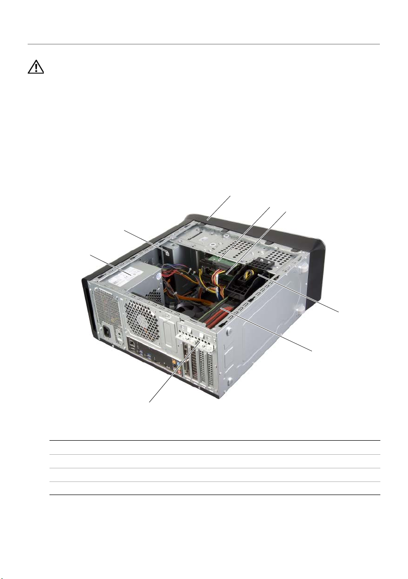
Inside View of Your Computer
1
2
3
8
7
4
6
1 front bezel 2 primary hard-drive
3 secondary hard-drive 4 graphics-card bracket (optional)
5 graphics card 6 card retention bracket
7 power supply 8 optical drive
12 | Technical Overview
5
Page 13
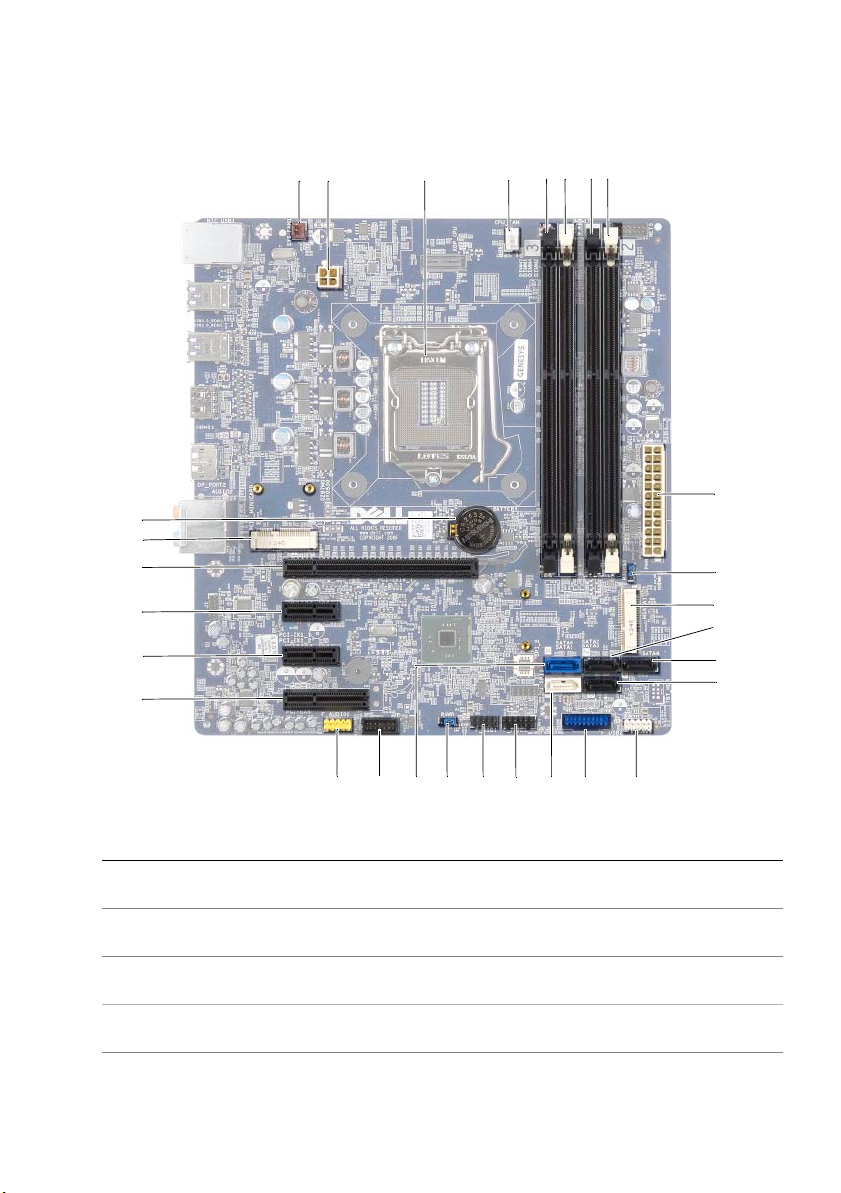
System-Board Components
1
2
29
28
27
26
25
24
55
4
6
3
78
9
10
11
12
13
14
23
1 chassis fan connector
(SYS_FAN 1)
3 processor socket 4 processor fan connector
5 memory module connector
(DIMM3)
7 memory module connector
(DIMM4)
9 main power connector
(PWR1)
2122
19
20
18
17
2 power connector (PWRCONN1)
(CPU_FAN)
6 memory module connector
(DIMM1)
8 memory module connector
(DIMM2)
10 CMOS reset jumper (RTCRST)
16
15
Technical Overview | 13
Page 14

11 mSATA slot (MSATA1) 12 SATA 3.0 (6 Gb/s) drive connector
13 SATA 3.0 (6 Gb/s) drive connector
(SATA 4)
15 front panel USB connector
(F_USB3)
17 SATA 3.0 (6 Gb/s) drive connector
(SATA 1)
19 front panel USB connector
(F_USB1)
21 SATA 3.0 (6 Gb/s) drive connector
(SATA 0)
23 front panel audio connector
(F_AUDIO1)
25 PCI-Express x1 card slot
(PCI-EX1_2)
27 PCI-Express x16 card slot
(PCI-EX16_1)
29 battery socket (BATTERY)
(SATA 2)
14 SATA 3.0 (6 Gb/s) drive connector
(SATA 3)
16 front panel USB connector
(F_USB2)
18 power button connector
(F_PANEL)
20 password reset jumper
(PSWD)
22 front panel USB connector
(F_USB4)
24 PCI-Express x1 card slot
(PCI-EX1_4)
26 PCI-Express x1 card slot
(PCI-EX1_1)
28 Mini-Card slot
(PCIE_MINICARD)
14 | Technical Overview
Page 15

Removing the Computer Cover
WARNING: Before working inside your computer, read the safety information
that shipped with your computer and follow the steps in "Before You Begin" on
page 9. After working inside your computer, follow the instructions in "After
Working Inside Your Computer" on page 11. For additional safety best practices
information, see the Regulatory Compliance Homepage at
dell.com/regulatory_compliance.
Procedure
1 Lay the computer on its side with the computer cover facing up.
2 Remove the thumbscrew that secures the computer cover to the chassis, using a
screw driver, if necessary.
3 Release the computer cover by sliding it away from the front of the computer.
4 Lift the cover away from the computer and set it aside in a secure location.
1
2
1 thumbscrew 2 computer cover
Removing the Computer Cover | 15
Page 16

Replacing the Computer Cover
WARNING: Before working inside your computer, read the safety information
that shipped with your computer and follow the steps in "Before You Begin" on
page 9. After working inside your computer, follow the instructions in "After
Working Inside Your Computer" on page 11. For additional safety best practices
information, see the Regulatory Compliance Homepage at
dell.com/regulatory_compliance.
Procedure
1 Connect all the cables and fold the cables out of the way.
2 Ensure that no tools or extra parts are left inside the computer.
3 Align the tabs at the bottom of the computer cover with the slots located along the
edge of the chassis.
4 Press the computer cover down and slide it towards the front of the computer.
5 Replace the thumbscrew that secures the computer cover to the chassis.
6 Place the computer in an upright position.
Postrequisites
Follow the instructions in "After Working Inside Your Computer" on page 11.
16 | Replacing the Computer Cover
Page 17
Removing the Memory Module(s)
WARNING: Before working inside your computer, read the safety information
that shipped with your computer and follow the steps in "Before You Begin" on
page 9. After working inside your computer, follow the instructions in "After
Working Inside Your Computer" on page 11. For additional safety best practices
information, see the Regulatory Compliance Homepage at
dell.com/regulatory_compliance.
Prerequisites
1 Remove the computer cover. See "Removing the Computer Cover" on page 15.
2 Remove the graphics card. See "Removing the Graphics Card" on page 26.
Procedure
WARNING: The memory module(s) may become hot during normal operation.
Allow the memory module(s) to cool before touching them.
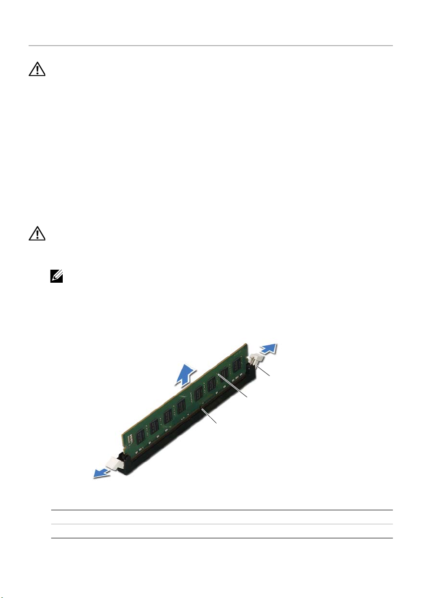
1 Press out the securing clip at each end of the memory-module connector.
NOTE: If the memory module is difficult to remove, gently ease the memory
module back and forth to remove it from the connector.
2 Grasp the memory module and pull it upward.
3
2
1
1 memory-module connector 2 memory module
3 securing clips (2)
Removing the Memory Module(s) | 17
Page 18
Replacing the Memory Module(s)
WARNING: Before working inside your computer, read the safety information
that shipped with your computer and follow the steps in "Before You Begin" on
page 9. After working inside your computer, follow the instructions in "After
Working Inside Your Computer" on page 11. For additional safety best practices
information, see the Regulatory Compliance Homepage at
dell.com/regulatory_compliance.
Procedure
CAUTION: If the memory module is not installed correctly, your computer may
not boot.
CAUTION: If you remove the original memory module(s) from your computer
during a memory upgrade, keep them separate from any new module(s) that you
may have, even if you purchased the new module(s) from Dell. If possible, do not
pair an original memory module with a new memory module. Otherwise, your
computer may not start properly.
The recommended memory configurations are:
matched memory modules installed in DIMM connectors 1 and 2 and another
matched memory modules installed in DIMM connectors 3 and 4.
18 | Replacing the Memory Module(s)
Page 19
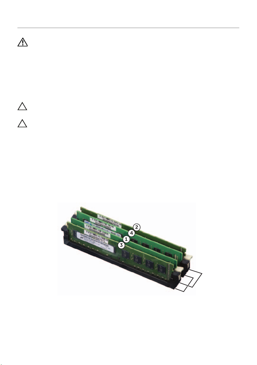
1 Press out the securing clip at each end of the memory-module connector.
2 Align the notch on the bottom of the memory module with the tab on the
memory-module connector.
5
4
3
2
1
1 cutouts (2) 2 memory-module connector
3tab 4notch
5memory module
Replacing the Memory Module(s) | 19
Page 20

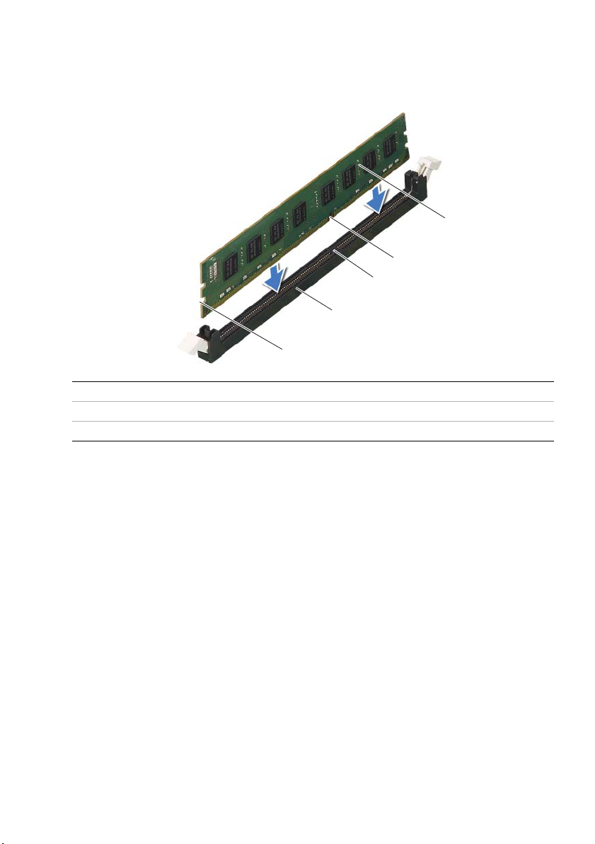
3 Insert the memory module into the memory-module connector until the memory
module snaps into position.
If you insert the memory module correctly, the securing clips snap into the cutouts
at each end of the memory module.
3
2
1
1 securing clip (snapped in position) 2 memory-module connector
3memory module
Postrequisites
1 Replace the graphics card. See "Replacing the Graphics Card" on page 29.
2 Replace the computer cover. See "Replacing the Computer Cover" on page 16.
20 | Replacing the Memory Module(s)
Page 21

Removing the Front Bezel
WARNING: Before working inside your computer, read the safety information
that shipped with your computer and follow the steps in "Before You Begin" on
page 9. After working inside your computer, follow the instructions in "After
Working Inside Your Computer" on page 11. For additional safety best practices
information, see the Regulatory Compliance Homepage at
dell.com/regulatory_compliance.
Prerequisites
Remove the computer cover. See "Removing the Computer Cover" on page 15.
Removing the Front Bezel | 21
Page 22
Procedure
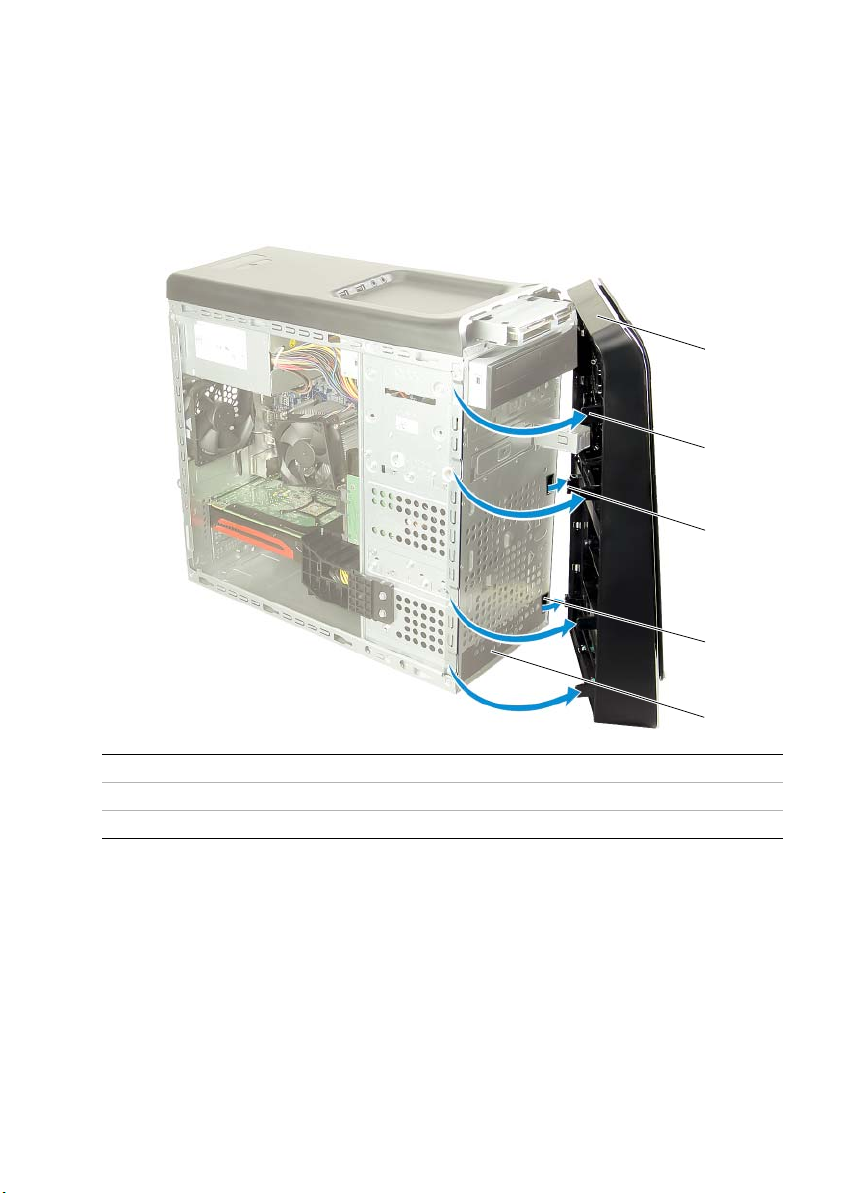
1 Place the computer in an upright position.
2 Grasp and release the front bezel tabs sequentially, one at a time by moving them
outward from the front panel.
3 Rotate and pull the front bezel away from the front of the computer to release the
front bezel clamps from the front panel slots.
1
2
3
4
1 front bezel 2 front bezel tabs (4)
3 front bezel clamps (3) 4 front panel slots (3)
5 front panel
22 | Removing the Front Bezel
5
Page 23

Replacing the Front Bezel
WARNING: Before working inside your computer, read the safety information
that shipped with your computer and follow the steps in "Before You Begin" on
page 9. After working inside your computer, follow the instructions in "After
Working Inside Your Computer" on page 11. For additional safety best practices
information, see the Regulatory Compliance Homepage at
dell.com/regulatory_compliance.
Procedure
1 Align and insert the front bezel clamps into the front panel slots.
2 Rotate the front bezel towards the computer until the front bezel tabs snap into
place.
Postrequisites
Replace the computer cover. See "Replacing the Computer Cover" on page 16.
Replacing the Front Bezel | 23
Page 24
Removing the Graphics-Card Bracket (optional)
WARNING: Before working inside your computer, read the safety information
that shipped with your computer and follow the steps in "Before You Begin" on
page 9. After working inside your computer, follow the instructions in "After
Working Inside Your Computer" on page 11. For additional safety best practices
information, see the Regulatory Compliance Homepage at
dell.com/regulatory_compliance.
Prerequisites
Remove the computer cover. See "Removing the Computer Cover" on page 15.
Procedure
1 Remove the screws that secure the graphics-card bracket to the chassis.
2 Lift the graphics-card bracket off the chassis.
3 Set the graphics-card bracket aside in a secure location.
1
1 screws (2) 2 graphics-card bracket
24 | Removing the Graphics-Card Bracket (optional)
2
Page 25

Replacing the Graphics-Card Bracket (optional)
WARNING: Before working inside your computer, read the safety information
that shipped with your computer and follow the steps in "Before You Begin" on
page 9. After working inside your computer, follow the instructions in "After
Working Inside Your Computer" on page 11. For additional safety best practices
information, see the Regulatory Compliance Homepage at
dell.com/regulatory_compliance.
Procedure
1 Align the screw holes on the graphics-card bracket with the screw holes on the
chassis.
2 Replace the screws that secure the graphics-card bracket to the chassis..
Postrequisites
Replace the computer cover. See "Replacing the Computer Cover" on page 16.
Replacing the Graphics-Card Bracket (optional) | 25
Page 26

Removing the Graphics Card
WARNING: Before working inside your computer, read the safety information
that shipped with your computer and follow the steps in "Before You Begin" on
page 9. After working inside your computer, follow the instructions in "After
Working Inside Your Computer" on page 11. For additional safety best practices
information, see the Regulatory Compliance Homepage at
dell.com/regulatory_compliance.
The system board of your computer is equipped with one PCI-Express x16
connector to install graphics card. To locate the PCI-Express x16 connector on
the system board, see "System-Board Components" on page 13.
Prerequisites
1 Remove the computer cover. See "Removing the Computer Cover" on page 15.
2 Remove the graphics-card bracket, if applicable. See "Removing the Graphics-Card
Bracket (optional)" on page 24.
26 | Removing the Graphics Card
Page 27

Procedure
1 Remove the screw that secures the card-retention bracket to the chassis.
2 Lift the card-retention bracket and set it aside in a secure location.
NOTE: Your graphics card may have power-cable connectors.
3 Press the releasing clips on the power-cable connectors and disconnect the power
cable from the graphics card, if applicable.
1
2
3
1power cable 2screw
3 card-retention bracket
4 Locate the graphics card (PCI-Express x16 card) on the system board.
See "System-Board Components" on page 13.
NOTE: The appearence of the securing tab may be different on your
computer.
Removing the Graphics Card | 27
Page 28

5 Press and hold the securing tab on the card connector, grasp the card by its top
corners, and then ease the card out of the card connector.
1
2
1 securing tab 2 graphics card
28 | Removing the Graphics Card
Page 29

Replacing the Graphics Card
WARNING: Before working inside your computer, read the safety information
that shipped with your computer and follow the steps in "Before You Begin" on
page 9. After working inside your computer, follow the instructions in "After
Working Inside Your Computer" on page 11. For additional safety best practices
information, see the Regulatory Compliance Homepage at
dell.com/regulatory_compliance.
Procedure
1 Align the graphics card with the PCI-Express x16 card connector on the system
board.
2 Place the card in the connector and press down firmly. Ensure that the card is firmly
seated in the slot.
3 Connect the power cable to the graphics card, if applicable.
4 Replace the card-retention bracket, ensuring that:
• The guide clamp is aligned with the guide notch.
• The top of all cards and filler brackets are flush with the alignment bar.
• The notch on top of the card or filler bracket fits around the alignment guide.
5 Replace the screw that secures the card-retention bracket.
Postrequisites
1 Replace the graphics-card bracket, if applicable. See "Replacing the Graphics-Card
Bracket (optional)" on page 25.
2 Replace the computer cover. See "Replacing the Computer Cover" on page 16.
Replacing the Graphics Card | 29
Page 30

Removing the Wireless Mini-Card
WARNING: Before working inside your computer, read the safety information
that shipped with your computer and follow the steps in "Before You Begin" on
page 9. After working inside your computer, follow the instructions in "After
Working Inside Your Computer" on page 11. For additional safety best practices
information, see the Regulatory Compliance Homepage at
dell.com/regulatory_compliance.
Prerequisites
Remove the computer cover. See "Removing the Computer Cover" on page 15.
Procedure
1 Disconnect the antenna cables from the wireless mini-card.
2 Remove the screws that secure the wireless mini-card to the system board.
1
2
1 screws (2) 2 antenna cables (2)
30 | Removing the Wireless Mini-Card
Page 31

3 Slide and remove the wireless mini-card out of the wireless mini-card connector.
1 wireless mini-card connector 2 wireless mini-card
Removing the Wireless Mini-Card | 31
Page 32

Replacing the Wireless Mini-Card
WARNING: Before working inside your computer, read the safety information
that shipped with your computer and follow the steps in "Before You Begin" on
page 9. After working inside your computer, follow the instructions in "After
Working Inside Your Computer" on page 11. For additional safety best practices
information, see the Regulatory Compliance Homepage at
dell.com/regulatory_compliance.
Procedure
CAUTION: To avoid damage to the wireless mini-card, ensure that no cables are
placed under the wireless mini-card.
1 Align the notch on the wireless mini-card with the tab on the wireless
mini-card connector.
2 Insert the wireless mini-card at a 45-degree angle into the wireless
mini-card connector.
3 Press the outer end of the wireless mini-card down and replace the screws
that secure the wireless mini-card to the system board.
4 Connect the antenna cables to the wireless mini-card.
The following table provides the wireless-antenna cable color schemes for
the wireless mini-cards supported by your computer.
Connectors on the mini-card Wireless-antenna cable color schemes
WLAN + Bluetooth (two cables)
Main WLAN + Bluetooth (white triangle)
Auxiliary WLAN + Bluetooth (black triangle)
white
black
Postrequisites
Replace the computer cover. See "Replacing the Computer Cover" on page 16.
32 | Replacing the Wireless Mini-Card
Page 33

Removing the mSATA Drive
WARNING: Before working inside your computer, read the safety information
that shipped with your computer and follow the steps in "Before You Begin" on
page 9. After working inside your computer, follow the instructions in "After
Working Inside Your Computer" on page 11. For additional safety best practices
information, see the Regulatory Compliance Homepage at
dell.com/regulatory_compliance.
Prerequisites
Remove the computer cover. See "Removing the Computer Cover" on page 15.
Procedure
1 Remove the screws that secure the mSATA drive to the system board.
2 Lift the mSATA drive away from the system-board connector.
3
2
1
1 screws (2) 2 mSATA drive
3 mSATA-drive connector
Removing the mSATA Drive | 33
Page 34

Replacing the mSATA Drive
WARNING: Before working inside your computer, read the safety information
that shipped with your computer and follow the steps in "Before You Begin" on
page 9. After working inside your computer, follow the instructions in "After
Working Inside Your Computer" on page 11. For additional safety best practices
information, see the Regulatory Compliance Homepage at
dell.com/regulatory_compliance.
Procedure
1 Align the notch on the mSATA drive with the tab on the
system-board connector.
2 Insert the mSATA drive at a 45-degree angle into the
system-board connector.
3 Press the other end of the mSATA drive down and replace the screws that secure
the mSATA drive to the systemboard.
Postrequisites
Replace the computer cover. See "Replacing the Computer Cover" on page 16.
34 | Replacing the mSATA Drive
Page 35

Removing the Primary Hard-Drive
WARNING: Before working inside your computer, read the safety information
that shipped with your computer and follow the steps in "Before You Begin" on
page 9. After working inside your computer, follow the instructions in "After
Working Inside Your Computer" on page 11. For additional safety best practices
information, see the Regulatory Compliance Homepage at
dell.com/regulatory_compliance.
WARNING: If you remove the hard drive from the computer when the drive is
hot, do not touch the metal housing of the hard drive.
CAUTION: To avoid data loss, do not remove the hard drive while the computer is
on or in Sleep state.
CAUTION: Hard drives are fragile. Exercise care when handling the hard drive.
Prerequisites
Remove the computer cover. See "Removing the Computer Cover" on page 15.
Removing the Primary Hard-Drive | 35
Page 36

Procedure
1 Disconnect the power and data cables from the primary hard-drive.
2 Remove the screws that secure the hard drive to the chassis.
3 Slide the hard drive out towards the back of the computer.
4
3
2
1
1 power cable 2 data cable
3 primary hard-drive 4 screws (4)
36 | Removing the Primary Hard-Drive
Page 37

Replacing the Primary Hard-Drive
WARNING: Before working inside your computer, read the safety information
that shipped with your computer and follow the steps in "Before You Begin" on
page 9. After working inside your computer, follow the instructions in "After
Working Inside Your Computer" on page 11. For additional safety best practices
information, see the Regulatory Compliance Homepage at
dell.com/regulatory_compliance.
Procedure
1 Slide the primary hard-drive into the hard-drive cage.
2 Align the screw holes on the primary hard-drive with the screw holes on the chassis.
3 Replace the screws that secure the primary hard-drive to the chassis.
4 Connect the power and data cables to the primary hard-drive.
Postrequisites
Replace the computer cover. See "Replacing the Computer Cover" on page 16.
Replacing the Primary Hard-Drive | 37
Page 38

Removing the Hard-Drive Cage
WARNING: Before working inside your computer, read the safety information
that shipped with your computer and follow the steps in "Before You Begin" on
page 9. After working inside your computer, follow the instructions in "After
Working Inside Your Computer" on page 11. For additional safety best practices
information, see the Regulatory Compliance Homepage at
dell.com/regulatory_compliance.
Prerequisites
1 Remove the computer cover. See "Removing the Computer Cover" on page 15.
2 Remove the primary hard-drive. See "Removing the Primary Hard-Drive" on
page 35.
Procedure
1 If applicable, disconnect the power and data cables from the secondary hard-drive.
2 Remove the screws that secure the hard-drive cage to the chassis.
3 Slide and lift the hard-drive cage away from the chassis.
1
1 screws (3) 2 hard-drive cage
3 power cable 4 data cable
38 | Removing the Hard-Drive Cage
2
4
3
Page 39

Replacing the Hard-Drive Cage
WARNING: Before working inside your computer, read the safety information
that shipped with your computer and follow the steps in "Before You Begin" on
page 9. After working inside your computer, follow the instructions in "After
Working Inside Your Computer" on page 11. For additional safety best practices
information, see the Regulatory Compliance Homepage at
dell.com/regulatory_compliance.
Procedure
1 Align the screw holes on the hard-drive cage with the screw holes on the chassis.
2 Replace the screws that secure the hard-drive cage to the chassis.
3 If applicable, connect the power and data cables to the secondary hard-drive.
Postrequisites
1 Replace the primary hard-drive. See "Replacing the Primary Hard-Drive" on page 37.
2 Replace the computer cover. See "Replacing the Computer Cover" on page 16.
Replacing the Hard-Drive Cage | 39
Page 40

Removing the Secondary Hard-Drive (optional)
WARNING: Before working inside your computer, read the safety information
that shipped with your computer and follow the steps in "Before You Begin" on
page 9. After working inside your computer, follow the instructions in "After
Working Inside Your Computer" on page 11. For additional safety best practices
information, see the Regulatory Compliance Homepage at
dell.com/regulatory_compliance.
WARNING: If you remove the hard drive from the computer when the drive is
hot, do not touch the metal housing of the hard drive.
CAUTION: To avoid data loss, do not remove the hard drive while the computer is
on or in Sleep state.
CAUTION: Hard drives are fragile. Exercise care when handling the hard drive.
Prerequisites
1 Remove the computer cover. See "Removing the Computer Cover" on page 15.
2 Remove the primary hard-drive. See "Removing the Primary Hard-Drive" on
page 35.
3 Remove the hard-drive cage. See "Removing the Hard-Drive Cage" on page 38.
Procedure
1 Remove the screws that secure the secondary hard-drive to the hard-drive cage.
2 Slide the secondary hard-drive out from the hard-drive cage.
1
1 secondary hard-drive 2 screws (4)
3 hard-drive cage
2
40 | Removing the Secondary Hard-Drive (optional)
3
Page 41

Replacing the Secondary Hard-Drive (optional)
WARNING: Before working inside your computer, read the safety information
that shipped with your computer and follow the steps in "Before You Begin" on
page 9. After working inside your computer, follow the instructions in "After
Working Inside Your Computer" on page 11. For additional safety best practices
information, see the Regulatory Compliance Homepage at
dell.com/regulatory_compliance.
Procedure
1 Slide the secondary hard-drive into the hard-drive cage.
2 Replace the screws that secure the secondary hard-drive to the hard-drive cage.
Postrequisites
1 Replace the hard-drive cage. See "Replacing the Hard-Drive Cage" on page 39.
2 Replace the primary hard-drive. See "Replacing the Primary Hard-Drive" on page 37.
3 Replace the computer cover. See "Replacing the Computer Cover" on page 16.
Replacing the Secondary Hard-Drive (optional) | 41
Page 42

Installing a third Hard-Drive (optional)
WARNING: Before working inside your computer, read the safety information
that shipped with your computer and follow the steps in "Before You Begin" on
page 9. After working inside your computer, follow the instructions in "After
Working Inside Your Computer" on page 11. For additional safety best practices
information, see the Regulatory Compliance Homepage at
dell.com/regulatory_compliance.
CAUTION: Hard drives are fragile. Exercise care when handling the hard drive.
Prerequisites
1 Remove the computer cover. See "Removing the Computer Cover" on page 15.
2 Remove the front bezel. See "Removing the Front Bezel" on page 21.
Procedure
1 Insert a screw driver and twist it to remove the break-away metal plate.
2 Pull the break-away metal plate away from the chassis.
1 break-away metal plate
42 | Installing a third Hard-Drive (optional)
1
Page 43

3 Gently slide the third hard-drive into the hard-drive bay through the front of the
computer.
1
1 third hard-drive
Installing a third Hard-Drive (optional) | 43
Page 44

4 Replace the screws that secure the third hard-drive to the chassis.
5 Connect the power and data cables to the third hard-drive.
1
2
3
1 power cable 2 data cable
3screws (2)
Postrequisites
1 Replace the front bezel. See "Replacing the Front Bezel" on page 23.
2 Replace the computer cover. See "Replacing the Computer Cover" on page 16.
44 | Installing a third Hard-Drive (optional)
Page 45

Removing the Optical Drive
WARNING: Before working inside your computer, read the safety information
that shipped with your computer and follow the steps in "Before You Begin" on
page 9. After working inside your computer, follow the instructions in "After
Working Inside Your Computer" on page 11. For additional safety best practices
information, see the Regulatory Compliance Homepage at
dell.com/regulatory_compliance.
Prerequisites
1 Remove the computer cover. See "Removing the Computer Cover" on page 15.
2 Remove the front bezel. See "Removing the Front Bezel" on page 21.
Procedure
1 Disconnect the power and data cables from the optical drive.
2 Remove the screws that secure the optical drive to the chassis.
3 Push and slide the optical drive out through the front of the computer.
NOTE: Repeat steps 1 to 3 to remove secondary optical-drive, if applicable.
3
2
1
1 power cable 2 data cable
3 screws (2) 4 optical drive
4 Set aside the optical drive in a secure location.
Removing the Optical Drive | 45
4
Page 46

Replacing the Optical Drive
WARNING: Before working inside your computer, read the safety information
that shipped with your computer and follow the steps in "Before You Begin" on
page 9. After working inside your computer, follow the instructions in "After
Working Inside Your Computer" on page 11. For additional safety best practices
information, see the Regulatory Compliance Homepage at
dell.com/regulatory_compliance.
Procedure
1 Gently slide the optical drive into the optical-drive bay through the front of the
computer.
2 Align the screw holes on the optical drive with the screw holes on the chassis.
3 Replace the screws that secure the optical drive to the chassis.
4 Connect the power and data cables to the optical drive.
Postrequisites
1 Replace the front bezel. See "Replacing the Front Bezel" on page 23.
2 Replace the computer cover. See "Replacing the Computer Cover" on page 16.
46 | Replacing the Optical Drive
Page 47

Removing the Top Cover
WARNING: Before working inside your computer, read the safety information
that shipped with your computer and follow the steps in "Before You Begin" on
page 9. After working inside your computer, follow the instructions in "After
Working Inside Your Computer" on page 11. For additional safety best practices
information, see the Regulatory Compliance Homepage at
dell.com/regulatory_compliance.
Prerequisites
1 Remove the computer cover. See "Removing the Computer Cover" on page 15.
2 Remove the front bezel. See "Removing the Front Bezel" on page 21.
Procedure
1 Slide and lift the top cover away from top panel.
2 Set the top cover aside in a secure location.
1
1top cover
Removing the Top Cover | 47
Page 48

Replacing the Top Cover
WARNING: Before working inside your computer, read the safety information
that shipped with your computer and follow the steps in "Before You Begin" on
page 9. After working inside your computer, follow the instructions in "After
Working Inside Your Computer" on page 11. For additional safety best practices
information, see the Regulatory Compliance Homepage at
dell.com/regulatory_compliance.
Procedure
1 Align the tabs on the top cover with the slots on the top panel.
2 Press and slide the top cover towards the back of the computer, until it clicks into
place.
Postrequisites
1 Replace the front bezel. See "Replacing the Front Bezel" on page 23.
2 Replace the computer cover. See "Replacing the Computer Cover" on page 16.
48 | Replacing the Top Cover
Page 49

Removing the Media-Card Reader
WARNING: Before working inside your computer, read the safety information
that shipped with your computer and follow the steps in "Before You Begin" on
page 9. After working inside your computer, follow the instructions in "After
Working Inside Your Computer" on page 11. For additional safety best practices
information, see the Regulatory Compliance Homepage at
dell.com/regulatory_compliance.
Prerequisites
1 Remove the computer cover. See "Removing the Computer Cover" on page 15.
2 Remove the front bezel. See "Removing the Front Bezel" on page 21.
3 Remove the top cover. See "Removing the Top Cover" on page 47.
Procedure
1 Remove the screws that secure the media-card reader to the front panel. The
screws are located below the media-card reader.
2 Disconnect the media-card reader cable from the media-card reader.
3 Slide and lift the media-card reader to remove it from the top panel.
2
1
1 media-card reader cable 2 media-card reader
3 screws (2) 4 front panel
Removing the Media-Card Reader | 49
3
4
Page 50

Replacing the Media-Card Reader
WARNING: Before working inside your computer, read the safety information
that shipped with your computer and follow the steps in "Before You Begin" on
page 9. After working inside your computer, follow the instructions in "After
Working Inside Your Computer" on page 11. For additional safety best practices
information, see the Regulatory Compliance Homepage at
dell.com/regulatory_compliance.
Procedure
1 Gently slide the media-card reader guides into the slots in the top panel
2 Replace the screws that secure the media-card reader to the front panel
3 Connect the media-card reader cable to the media-card reader.
Postrequisites
1 Replace the top cover. See "Replacing the Top Cover" on page 48.
2 Replace the front bezel. See "Replacing the Front Bezel" on page 23.
3 Replace the computer cover. See "Replacing the Computer Cover" on page 16.
50 | Replacing the Media-Card Reader
Page 51

Removing the Top I/O Panel
WARNING: Before working inside your computer, read the safety information
that shipped with your computer and follow the steps in "Before You Begin" on
page 9. After working inside your computer, follow the instructions in "After
Working Inside Your Computer" on page 11. For additional safety best practices
information, see the Regulatory Compliance Homepage at
dell.com/regulatory_compliance.
Prerequisites
1 Remove the computer cover. See "Removing the Computer Cover" on page 15.
2 Remove the front bezel. See "Removing the Front Bezel" on page 21.
3 Remove the top cover. See "Removing the Top Cover" on page 47.
Procedure
1 Disconnect the top I/O panel cables from the system board connectors, F_USB3
and F_AUDIO1. See "System-Board Components" on page 13.
2 Remove the screws that secure the top I/O panel to the top panel.
3 Slide and lift the top I/O panel from the top panel.
Removing the Top I/O Panel | 51
Page 52

1
2
3
4
5
1 top I/O panel 2 top panel
3 screws (2) 4 USB cable connector (F_USB3)
5 Audio cable connector (F_AUDIO1)
52 | Removing the Top I/O Panel
Page 53

Replacing the Top I/O Panel
WARNING: Before working inside your computer, read the safety information
that shipped with your computer and follow the steps in "Before You Begin" on
page 9. After working inside your computer, follow the instructions in "After
Working Inside Your Computer" on page 11. For additional safety best practices
information, see the Regulatory Compliance Homepage at
dell.com/regulatory_compliance.
Procedure
1 Align the screw holes on the top I/O panel with the screw holes on the top panel.
2 Replace the screws that secure the top I/O panel to the top panel.
3 Connect the top I/O panel cables to the system board connectors, F_USB3 and
F_AUDIO1. See "System-Board Components" on page 13.
Postrequisites
1 Replace the top cover. See "Replacing the Top Cover" on page 48.
2 Replace the front bezel. See "Replacing the Front Bezel" on page 23.
3 Replace the computer cover. See "Replacing the Computer Cover" on page 16.
Replacing the Top I/O Panel | 53
Page 54

Removing the Front USB Panel
WARNING: Before working inside your computer, read the safety information
that shipped with your computer and follow the steps in "Before You Begin" on
page 9. After working inside your computer, follow the instructions in "After
Working Inside Your Computer" on page 11. For additional safety best practices
information, see the Regulatory Compliance Homepage at
dell.com/regulatory_compliance.
Prerequisites
1 Remove the computer cover. See "Removing the Computer Cover" on page 15.
2 Remove the front bezel. See "Removing the Front Bezel" on page 21.
Procedure
CAUTION: When sliding the front USB panel out of the computer, be extremely
careful. Carelessness may result in damage to the cable connectors and the cable
routing clips.
NOTE: Note the routing of all cables as you remove them so that you can re-route
them correctly after you replace the front USB panel.
1 Disconnect the front USB panel cables from the system board connector F_USB2.
See "System-Board Components" on page 13.
2 Remove the screw that secures the front USB panel to the front panel.
3 Slide the front USB panel down and pull it away.
54 | Removing the Front USB Panel
Page 55

3
1 front USB panel 2 screw
3 USB panel cables
1
2
Removing the Front USB Panel | 55
Page 56

Replacing the Front USB Panel
WARNING: Before working inside your computer, read the safety information
that shipped with your computer and follow the steps in "Before You Begin" on
page 9. After working inside your computer, follow the instructions in "After
Working Inside Your Computer" on page 11. For additional safety best practices
information, see the Regulatory Compliance Homepage at
dell.com/regulatory_compliance.
Procedure
1 Align and slide the front USB panel clamps into the front USB panel clamp slot.
2 Replace the screw that secures the front USB panel to the front panel.
3 Connect the front USB panel cables to the system board connector F_USB2. See
"System-Board Components" on page 13.
Postrequisites
1 Replace the front bezel. See "Replacing the Front Bezel" on page 23.
2 Replace the computer cover. See "Replacing the Computer Cover" on page 16.
56 | Replacing the Front USB Panel
Page 57

Removing the Power Button Module
WARNING: Before working inside your computer, read the safety information
that shipped with your computer and follow the steps in "Before You Begin" on
page 9. After working inside your computer, follow the instructions in "After
Working Inside Your Computer" on page 11. For additional safety best practices
information, see the Regulatory Compliance Homepage at
dell.com/regulatory_compliance.
Prerequisites
1 Remove the computer cover. See "Removing the Computer Cover" on page 15.
2 Remove the front bezel. See "Removing the Front Bezel" on page 21.
3 Remove the top cover. See "Removing the Top Cover" on page 47.
Procedure
1 Disconnect the power button module cable from the system board connector
F_PANEL. See "System-Board Components" on page 13.
2 Press the tabs on the power button module and lift the power button module to
release it from the top panel.
Removing the Power Button Module | 57
Page 58

1
1 power button module cable 2 power button module tabs (4)
3 power button module
2
58 | Removing the Power Button Module
3
Page 59

Replacing the Power Button Module
WARNING: Before working inside your computer, read the safety information
that shipped with your computer and follow the steps in "Before You Begin" on
page 9. After working inside your computer, follow the instructions in "After
Working Inside Your Computer" on page 11. For additional safety best practices
information, see the Regulatory Compliance Homepage at
dell.com/regulatory_compliance.
Procedure
1 Align and push the power button module tabs into the slots on the top panel.
2 Connect the power button module cable from the system board connector
F_PANEL. See "System-Board Components" on page 13.
Postrequisites
1 Replace the top cover. See "Replacing the Top Cover" on page 48.
2 Replace the front bezel. See "Replacing the Front Bezel" on page 23.
3 Replace the computer cover. See "Replacing the Computer Cover" on page 16.
Replacing the Power Button Module | 59
Page 60

Removing the Chassis Fan
WARNING: Before working inside your computer, read the safety information
that shipped with your computer and follow the steps in "Before You Begin" on
page 9. After working inside your computer, follow the instructions in "After
Working Inside Your Computer" on page 11. For additional safety best practices
information, see the Regulatory Compliance Homepage at
dell.com/regulatory_compliance.
Prerequisites
Remove the computer cover. See "Removing the Computer Cover" on page 15.
Procedure
1 Disconnect the chassis fan cable from the system board connector SYS_FAN1. See
"System-Board Components" on page 13.
2 Remove the screws that secure the chassis fan to the chassis.
3 Slide and lift the chassis fan away from the computer.
1
2
3
1 chassis fan cable 2 screws (4)
3 chassis fan
60 | Removing the Chassis Fan
Page 61

Replacing the Chassis Fan
WARNING: Before working inside your computer, read the safety information
that shipped with your computer and follow the steps in "Before You Begin" on
page 9. After working inside your computer, follow the instructions in "After
Working Inside Your Computer" on page 11. For additional safety best practices
information, see the Regulatory Compliance Homepage at
dell.com/regulatory_compliance.
Procedure
1 Align the screw holes on the chassis fan with the screw holes on the chassis.
2 Replace the screws that secure the chassis fan to the chassis.
3 Connect the chassis fan cable to the system board connector SYS_FAN1. See
"System-Board Components" on page 13.
Postrequisites
Replace the computer cover. See "Replacing the Computer Cover" on page 16.
Replacing the Chassis Fan | 61
Page 62

Removing the Processor Fan and Heat-Sink
WARNING: Before working inside your computer, read the safety information
that shipped with your computer and follow the steps in "Before You Begin" on
page 9. After working inside your computer, follow the instructions in "After
Working Inside Your Computer" on page 11. For additional safety best practices
information, see the Regulatory Compliance Homepage at
dell.com/regulatory_compliance.
WARNING: The heat sink may be hot during normal operation. Provide sufficient
time for the heat-sink to cool before you touch it.
CAUTION: To ensure maximum cooling for the processor, do not touch the heat
transfer areas on the processor fan and heat-sink assembly. The oils in your skin
can reduce the heat transfer capability of the thermal grease.
CAUTION: The processor fan and heat-sink assembly is a single unit. Do not try to
remove the fan separately.
Prerequisites
Remove the computer cover. See "Removing the Computer Cover" on page 15.
Procedure
1 Disconnect the processor fan cable from the system board connector CPU_FAN.
See "System-Board Components" on page 13.
2 Using a flat-blade screwdriver loosen the four captive screws that secure the
processor fan and heat-sink assembly to the system board.
3 Lift the processor fan and heat-sink assembly out of the computer.
62 | Removing the Processor Fan and Heat-Sink
Page 63

1
1 processor fan cable 2 processor fan and heat-sink assembly
3 captive screws (4)
2
3
Removing the Processor Fan and Heat-Sink | 63
Page 64

Replacing the Processor Fan and Heat-Sink
WARNING: Before working inside your computer, read the safety information
that shipped with your computer and follow the steps in "Before You Begin" on
page 9. After working inside your computer, follow the instructions in "After
Working Inside Your Computer" on page 11. For additional safety best practices
information, see the Regulatory Compliance Homepage at
dell.com/regulatory_compliance.
Procedure
1 Clean the thermal grease from the bottom of the heat-sink.
2 Apply new thermal grease to the top of the processor, if applicable.
3 Place the processor fan and heat-sink assembly over the processor.
4 Align the captive screws on the processor fan and heat-sink assembly with the
screw holes on the system board.
5 Tighten the captive screws that secure the processor fan and heat-sink assembly to
the system board
6 Connect the processor fan cable to the system board connector CPU_FAN. See
"System-Board Components" on page 13.
Postrequisites
Replace the computer cover. See "Replacing the Computer Cover" on page 16.
64 | Replacing the Processor Fan and Heat-Sink
Page 65

Removing the Processor
WARNING: Before working inside your computer, read the safety information
that shipped with your computer and follow the steps in "Before You Begin" on
page 9. After working inside your computer, follow the instructions in "After
Working Inside Your Computer" on page 11. For additional safety best practices
information, see the Regulatory Compliance Homepage at
dell.com/regulatory_compliance.
CAUTION: Processors are fragile. Handle the processor only by the edges and do
not touch the metal pins.
Prerequisites
1 Remove the computer cover. See "Removing the Computer Cover" on page 15.
WARNING: Despite having a plastic shield, the processor fan and heat-sink
assembly may be very hot during normal operation. Ensure that it has had
sufficient time to cool before you touch it.
NOTE: Unless a new processor fan and heat-sink assembly is required for the
new processor, reuse the original processor fan and heat-sink assembly when
you replace the processor.
2 Remove the processor fan and heat-sink. See "Removing the Processor Fan and
Heat-Sink" on page 62.
Procedure
1 Press the release-lever down and then pull it outwards to release it from the
securing tab.
2 Extend the release-lever completely to open the processor cover.
Removing the Processor | 65
Page 66

3 Gently lift the processor and remove it from the processor socket.
1
1 release lever 2 securing tab
3 processor cover 4 socket
5 processor
2
3
5
4
66 | Removing the Processor
Page 67

Replacing the Processor
WARNING: Before working inside your computer, read the safety information
that shipped with your computer and follow the steps in "Before You Begin" on
page 9. After working inside your computer, follow the instructions in "After
Working Inside Your Computer" on page 11. For additional safety best practices
information, see the Regulatory Compliance Homepage at
dell.com/regulatory_compliance.
NOTE: The original thermal grease can be reused if the original processor and
processor heat-sink are reinstalled together. If either the processor or the
processor heat-sink is replaced, use the thermal grease provided in the kit to ensure
that thermal conductivity is achieved. Ensure that the release lever on the processor
socket is fully extended in the open position.
Replacing the Processor | 67
Page 68

Procedure
1 Ensure that the release lever on the processor socket is fully extended in the open
position.
CAUTION: You must position the processor correctly in the processor socket to
avoid permanent damage to the processor.
2 Align the notches on the processor with the tabs on the processor socket.
3 Align the pin-1 corner on the processor with the pin-1 corner on the
processor socket, and then place the processor in the processor socket.
CAUTION: Ensure that the processor-cover notch is positioned underneath the
alignment post.
4 When the processor is fully seated in the socket, close the processor cover.
5 Pivot the release-lever down and place it under the tab on the processor cover.
1
3
2
1 processor pin-1 indicator 2 processor
3 alignment tabs (2) 4 alignment post
5 processor-cover notch 6 processor cover
7release lever
4
5
6
7
Postrequisites
1 Replace the processor fan and heat-sink. See "Replacing the Processor Fan and
Heat-Sink" on page 64.
2 Replace the computer cover. See "Replacing the Computer Cover" on page 16.
68 | Replacing the Processor
Page 69

Removing the Coin-Cell Battery
WARNING: Before working inside your computer, read the safety information
that shipped with your computer and follow the steps in "Before You Begin" on
page 9. After working inside your computer, follow the instructions in "After
Working Inside Your Computer" on page 11. For additional safety best practices
information, see the Regulatory Compliance Homepage at
dell.com/regulatory_compliance.
CAUTION: Removing the coin-cell battery resets the BIOS settings to default.
It is recommended that you note the BIOS settings before removing the coin-cell
battery.
Prerequisites
Remove the computer cover. See "Removing the Computer Cover" on page 15.
Procedure
1 Locate the battery socket on the system board. See "System-Board Components"
on page 13.
2 Press the securing clip away from the coin-cell battery until the coin-cell battery
pops out.
3 Lift the coin-cell battery out of its socket.
12
1 coin-cell battery 2 securing clip
Removing the Coin-Cell Battery | 69
Page 70

Replacing the Coin-Cell Battery
WARNING: Before working inside your computer, read the safety information
that shipped with your computer and follow the steps in "Before You Begin" on
page 9. After working inside your computer, follow the instructions in "After
Working Inside Your Computer" on page 11. For additional safety best practices
information, see the Regulatory Compliance Homepage at
dell.com/regulatory_compliance.
WARNING: The battery may explode if installed incorrectly. Replace the battery
only with the same or equivalent type. Discard used batteries according to the
manufacturer’s instructions.
Procedure
Insert a new coin-cell battery (CR2032) into the battery socket with the positive side
facing up, and press the battery into place.
Postrequisites
Replace the computer cover. See "Replacing the Computer Cover" on page 16.
70 | Replacing the Coin-Cell Battery
Page 71

Removing the Power-Supply Unit
WARNING: Before working inside your computer, read the safety information
that shipped with your computer and follow the steps in "Before You Begin" on
page 9. After working inside your computer, follow the instructions in "After
Working Inside Your Computer" on page 11. For additional safety best practices
information, see the Regulatory Compliance Homepage at
dell.com/regulatory_compliance.
Prerequisites
Remove the computer cover. See "Removing the Computer Cover" on page 15.
Procedure
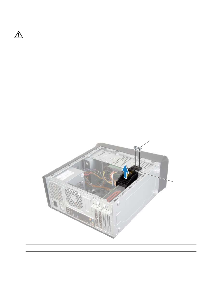
1 Disconnect the DC power cables from the system board and the drives. See
"System-Board Components" on page 13.
2 Remove the screws that secure the power-supply unit to the chassis.
3 Press the power-supply clamps to release the power-supply unit from the chassis.
4 Slide and lift the power-supply unit away from the chassis
3
2
1
1 screws (4) 2 power supply
3 power-supply clamps (2)
Removing the Power-Supply Unit | 71
Page 72

Replacing the Power-Supply Unit
WARNING: Before working inside your computer, read the safety information
that shipped with your computer and follow the steps in "Before You Begin" on
page 9. After working inside your computer, follow the instructions in "After
Working Inside Your Computer" on page 11. For additional safety best practices
information, see the Regulatory Compliance Homepage at
dell.com/regulatory_compliance.
Procedure
1 Slide the power supply towards the back of the chassis.
2 Align the screw holes on the power-supply unit with the screw holes on the chassis.
3 Replace the screws that secure the power-supply unit to the chassis.
4 Connect the DC power cables to the system board and the drives. See
"System-Board Components" on page 13.
Postrequisites
Replace the computer cover. See "Replacing the Computer Cover" on page 16.
72 | Replacing the Power-Supply Unit
Page 73

Removing the System Board
WARNING: Before working inside your computer, read the safety information
that shipped with your computer and follow the steps in "Before You Begin" on
page 9. After working inside your computer, follow the instructions in "After
Working Inside Your Computer" on page 11. For additional safety best practices
information, see the Regulatory Compliance Homepage at
dell.com/regulatory_compliance.
Prerequisites
1 Remove the computer cover. See "Removing the Computer Cover" on page 15.
2 Remove the wireless mini-card, if applicable. See "Removing the Wireless
Mini-Card" on page 30.
3 Remove the memory module(s). See "Removing the Memory Module(s)" on
page 17.
4 Remove the graphics card. See "Removing the Graphics Card" on page 26.
5 Remove the processor fan and heat-sink assembly. See "Removing the Processor
Fan and Heat-Sink" on page 62.
6 Remove the processor. See "Removing the Processor" on page 65.
Removing the System Board | 73
Page 74

Procedure
NOTE: Your computer’s service tag is stored in the system board. You must enter
the service tag in the BIOS after you replace the system board.
NOTE: Before disconnecting the cables from the system board, note the location
of the connectors, so that you can reconnect them correctly after you replace the
system board.
1 Disconnect all the cables connected to the system board.
2 Make note of the cable routing and remove the cables from the routing guides.
3 Remove the screws that secure the system board to the chassis.
2
1
1 screws (5) 2 system board
4 Lift the system board up and out of the chassis.
74 | Removing the System Board
Page 75

Replacing the System Board
WARNING: Before working inside your computer, read the safety information
that shipped with your computer and follow the steps in "Before You Begin" on
page 9. After working inside your computer, follow the instructions in "After
Working Inside Your Computer" on page 11. For additional safety best practices
information, see the Regulatory Compliance Homepage at
dell.com/regulatory_compliance.
Procedure
1 Gently place the system board into the chassis and slide it towards the back of the
computer.
2 Replace the screws that secure the system board to the chassis.
3 Route and connect the cables that you disconnected from the system board.
NOTE: For information on system board connectors, See "System-Board
Components" on page 13.
Postrequisites
1 Replace the processor. See "Replacing the Processor" on page 67.
2 Replace the processor fan and heat-sink assembly. See "Replacing the Processor
Fan and Heat-Sink" on page 64.
3 Replace the graphics card. See "Replacing the Graphics Card" on page 29.
4 Replace the memory module(s). See "Replacing the Memory Module(s)" on page 18.
5 Replace the wireless mini-card, if applicable. See "Replacing the Wireless
Mini-Card" on page 32.
6 Replace the computer cover. See "Replacing the Computer Cover" on page 16.
Entering the Service Tag in system setup
1 Turn on the computer.
2 Press <F2> during POST to enter the system setup program.
3 Navigate to the Main tab and enter the Service Tag in the Service Tag Input field. See
"System Setup" on page 76.
Replacing the System Board | 75
Page 76

System Setup
Overview
Use system setup to:
• Get information about the hardware installed in your computer, such as the
amount of RAM, the size of the hard drive, and so on
• Change the system configuration information
• Set or change a user-selectable option, such as the user password, type of
hard drive installed, enabling or disabling base devices, and so on
CAUTION: Unless you are an expert computer user, do not change the settings in
the system setup program. Certain changes can make your computer work
incorrectly.
NOTE: Before you change system setup, it is recommended that you write down
the system setup screen information for future reference.
Entering System Setup
1 Turn on (or restart) your computer.
2 During POST, when the DELL logo is displayed, watch for the F2 prompt to appear
and then press <F2> immediately.
NOTE: The F2 prompt indicates that the keyboard has initialized. This prompt
can appear very quickly, so you must watch for it, and then press <F2>. If you
press <F2> before the F2 prompt, this keystroke is lost. If you wait too long and
the operating system logo appears, continue to wait until you see the
operating system’s desktop. Then, turn off your computer and try again.
76 | System Setup
Page 77

System Setup Screens
The system setup screen displays current or changeable configuration information for
your computer. Information on the screen is divided into three areas: the setup item,
active help screen, and key functions.
Setup Item — This field appears on the left
side of the system setup window. This field
is a scrollable list containing features that
define the configuration of your computer,
including installed hardware, power
conservation, and security features.
Scroll up and down the list with the up- and
down-arrow keys. As an option is
highlighted, the Help Screen displays more
information about that option and available
settings.
Key Functions — This field appears below the Help Screen and lists keys and their
functions within the active system setup field.
Help Screen — This field appears on the
right side of the system setup window
and contains information about each
option listed in the Setup Item. In this
field you can view information about
your computer and make changes to
your current settings.
Press the up- and down-arrow keys to
highlight an option. Press <Enter> to
make that selection active and return to
the Setup Item.
NOTE: Not all settings listed in the
Setup Item are changeable.
System Setup Options
NOTE: Depending on your computer and installed devices, the items listed in this
section may appear, or may not appear exactly as listed.
Main→ System Information
BIOS Revision Display the BIOS revision.
BIOS Build Date Displays the BIOS release date.
System Name Displays the system name.
System Time (hh:mm:ss) Displays the current date.
System Date (mm:dd:yy) Displays the current time.
Service Tag Displays the Service Tag of your computer.
Service Tag Input Allows you to enter the Service Tag of your computer
only if the Service Tag is not present.
Asset Tag Displays the Asset Tag of the computer.
System Setup | 77
Page 78

Main→ Processor Information
Processor Type Displays the processor type.
Processor ID Displays the processor identification code.
Processor Core Count Displays the number of processor cores in your
computer.
Processor L1 Cache Displays the processor’s total L1 cache size.
Processor L2 Cache Displays the processor’s total L2 cache size.
Processor L3 Cache Displays the processor’s total L3 cache size.
Main→ Memory Information
Memory Installed Displays the total memory (RAM) installed in
your computer.
Memory Available Displays the amount of memory (RAM) available on
your computer.
Memory Running Speed Displays the running speed of the memory (RAM) in
your computer.
Memory Technology Displays the type of memory (RAM) technology used
in your computer.
Main→ SATA Information
SATA 0
Device Type Displays the type of device connected.
Device ID Displays the device identification code.
Device Size Displays the size of the SATA device present in
your computer.
SATA 1
Device Type Displays the type of device connected.
Device ID Displays the device identification code.
Device Size Displays the size of the SATA device present in
your computer.
SATA 2
Device Type Displays the type of device connected.
Device ID Displays the device identification code.
Device Size Displays the size of the SATA device present in
your computer.
78 | System Setup
Page 79

SATA 3
Device Type Displays the type of device connected.
Device ID Displays the device identification code.
Device Size Displays the size of the SATA device present in
your computer.
mSATA Device
Device Type Displays the type of device connected.
Device ID Displays the device identification code.
Device Size Displays the size of the mSATA device present in
your computer.
Advanced→ Processor Configuration
Intel(R) Hyper-Threading
Technology
Intel(R) SpeedStep
Technology
Intel(R) Virtualization
Technology
CPU XD Support If enabled, allows your computer to use Executive
Limit CPUID Value If enabled, limits the maximum value the processor
Multi Core Support If enabled, allows your computer to use all cores
Intel(R) Turbo Boost
Technology
Advanced→ USB Configuration
Front USB Ports Allows you to enable or disable the USB ports at the
Rear USB Ports Allows you to enable or disable the USB ports at the
Top USB Ports Allows you to enable or disable the USB ports at the
If enabled, each physical processor core appears as
two logical processor cores.
If enabled, the processor clock speed and core
voltage are adjusted dynamically based on the
processor load.
If enabled, a Virtual Machine Monitor (VMM) can
access your computer.
Display (XD) to hinder software that exploits buffer
overflows.
NOTE: Windows 8 enables this feature even if this
feature is set to disabled.
CPUID function supports.
available in the processor.
If enabled, allows your computer to use turbo boost
when required.
front of your computer.
back of your computer.
top of your computer.
System Setup | 79
Page 80

Advanced→ Onboard Device Configuration
Onboard Audio Controller Allows you to enable or disable the onboard
audio controller.
SATA Mode Allows you to configure the integrated hard drive
controller to ATA or AHCI.
Onboard LAN Controller Allows you to enable or disable the onboard
LAN controller.
Onboard LAN Boot ROM Allows you to enable or disable the ROM of the
onboard LAN controller.
Boot→ Boot Settings Configuration
Numlock Key Select power-on state for numlock.
Keyboard Errors Displays keyboard-related errors during boot.
USB Boot Support Allows you to enable or disable booting from
USB mass-storage devices.
Boot Mode Allows you to select the type of boot.
Secure Boot Control Allows you to enable or disable the secure
boot control.
NOTE: To enable this feature, the computer must be
in the UEFI boot mode and the Load Legacy OPROM
must be set to never.
Secure Boot Mode Allows you to select custom (clear secure boot
database) or standard (fixed secure boot policy)
secure boot mode.
Boot→ Clear Secure Boot Database
Manage All Keys (PK, KEK,
db, dbx)
Delete All Keys Allows you to delete all the keys.
Reset All Keys Allows you to reset all the keys.
Load Legacy OPROM Allows you to load the legacy OPROM when in the
1st Boot Displays the first boot device.
2nd Boot Displays the second boot device.
3rd Boot Displays the third boot device.
4th Boot Displays the fourth boot device.
5th Boot Displays the fifth boot device.
Displays the keys in the database.
UEFI boot mode.
80 | System Setup
Page 81

Power
Wake Up by Integrated
LAN/WLAN
AC Recovery Allows you to select the action the computer takes
DeepSx Power Policies Allows you to configure the DeepSx mode.
Auto Power On Allows the computer to start up automatically at a
Auto Power On Mode Allows you to set the auto power-on mode.
Auto Power On Date Allows you to set the auto power-on date.
Auto Power On Time Allows you to set the auto power-on time.
Intel Smart Connect
Technology
Security
Unlock Setup If the supervisor password is set, enter the password
Supervisor Password Displays the status of the supervisor password.
User Password Displays the status of the user password.
Set Supervisor Password Allows you to set a supervisor password.
User Access Level Allows you to set the user-access level.
Set User Password Allows you to set a user password.
Password Check Allows you to configure when the computer
Security→ TPM Security
TPM Security Support Allows you to enable or disable the TPM (Trusted
TPM Status Allows you to activate or deactivate the TPM security
Clear TPM If enabled, clears the TPM module settings.
TPM ACPI Support Allows you to enable or disable the
TPM PPI Provision
Override
If enabled, will wake the system using a
network message.
when power is restored.
pre-configured time.
Allows you to disable or enable the Intel Smart
Connect Technology.
to display the setup options.
prompts for passwords. (When entering system
setup or at every boot.)
Platform Module) security.
support.
TPM ACPI support.
Allows you to enable or disable TPM PPI
provision override.
System Setup | 81
Page 82

TPM PPI Deprovision
Override
Exit
Save Changes and Reset Allows you to save the changes.
Discard Changes and Reset Allows you to discard the changes.
Load Default Allows you to load the default BIOS settings.
Allows you to enable or disable TPM PPI
deprovision override.
Changing Boot Sequence
Changing Boot Sequence for the Current Boot
You can use this feature to change the current boot sequence, for example, to boot from
the optical drive to run Dell Diagnostics from the Drivers and Utilities disc.
The previous boot sequence is restored at the next boot.
1 If you are booting from a USB device, connect the USB device to a USB port.
2 Turn on (or restart) your computer.
3 When F2 Setup, F12 Boot Options appears in the lower-right corner of the
screen, press <F12>.
NOTE: If you wait too long and the operating system logo appears, continue to
wait until you see the operating system’s desktop. Then shut down your
computer and try again.
The Boot Device Menu appears, listing all available boot devices.
4 On the Boot Device Menu choose the device you want to boot from.
For example, if you are booting to a USB memory key, highlight
USB Storage Device and press <Enter>.
Changing Boot Sequence for Future Boots
1 Enter system setup. See "Entering System Setup" on page 76.
2 Use the arrow keys to highlight the Boot menu option and press <Enter> to access
the menu.
NOTE: Write down your current boot sequence in case you want to restore it.
3 Press the up- and down-arrow keys to move through the list of devices.
4 Press plus (+) or minus (–) to change the boot priority of the device.
82 | System Setup
Page 83

Clearing Forgotten Passwords
WARNING: Before working inside your computer, read the safety information
that shipped with your computer and follow the steps in "Before You Begin" on
page 9. After working inside your computer, follow the instructions in "After
Working Inside Your Computer" on page 11. For additional safety best practices
information, see the Regulatory Compliance Homepage at
dell.com/regulatory_compliance.
1 Remove the computer cover. See "Removing the Computer Cover" on page 15.
2 Locate the password jumper (PSWD) on the system board. See "System-Board
Components" on page 13.
3 Remove the 2-pin jumper plug from pins 2 and 3 and fix it on pins 1 and 2.
4 Wait for approximately five seconds to clear the password setting.
5 Remove the 2-pin jumper plug from pins 1 and 2 and replace it on pins 2 and 3.
6 Replace the computer cover. See "Replacing the Computer Cover" on page 16.
System Setup | 83
Page 84

Clearing CMOS Settings
WARNING: Before working inside your computer, read the safety information
that shipped with your computer and follow the steps in "Before You Begin" on
page 9. After working inside your computer, follow the instructions in "After
Working Inside Your Computer" on page 11. For additional safety best practices
information, see the Regulatory Compliance Homepage at
dell.com/regulatory_compliance.
1 Remove the computer cover. See "Removing the Computer Cover" on page 15.
2 Locate the CMOS jumper (RTCRST) on the system board. See "System-Board
Components" on page 13.
3 Remove the 2-pin jumper plug from pins 2 and 3 and fix it on pins 1 and 2.
4 Wait for approximately five seconds to clear the CMOS setting.
5 Remove the 2-pin jumper plug from pins 1 and 2 and replace it on pins 2 and 3.
6 Replace the computer cover. See "Replacing the Computer Cover" on page 16.
84 | System Setup
Page 85

Flashing the BIOS
The BIOS may require flashing when an update is available or when replacing the
system board. To flash the BIOS:
1 Turn on the computer.
2 Go to dell.com/support.
3 If you have your computer's Service Tag, type your computer's Service Tag and
click Submit.
If you do not have your computer's Service Tag, click Detect Service Tag to allow
automatic detection of your computer's Service Tag.
NOTE: If the Service Tag cannot be detected automatically, select your
product under the product categories.
4 Click Drivers & Downloads.
5 In the Operating System drop-down, select the operating system installed on
your computer.
6 Click BIOS.
7 Click Download File next to the latest version of the BIOS for your computer.
8 On the next page, select Single-file download and click Continue.
9 Save the file and once the download is complete, navigate to the folder where you
saved the BIOS update file.
10 Double-click the BIOS update file icon and follow the instructions on the screen.
Flashing the BIOS | 85
Page 86

More Information
To learn about Windows 8:
1 Turn on the computer.
2 Go to dell.com/support.
3 Type Windows 8 in the search box and click Search.
4 Click the links to learn about the Windows 8 features.
To learn about your computer features:
1 Follow the instructions from step 1 to step 3 in "Flashing the BIOS" on page 85.
2 Click Manuals & Documentation tab.
3View or Download the following documents to learn about your
computer features:
• Quick Start Guide: provides information about setting up your computer.
• Specifications: provides information about your computer specifications.
• Me and My Dell: provides information about your computer features.
86 | More Information
 Loading...