

Page 1

Dell™ XPS™ 8500
Owner’s Manual
Regulatory model: D03M
Regulatory type: D03M005
www.dell.com | support.dell.com/manuals
Page 2

Notes, Cautions, and Warnings
NOTE: A NOTE indicates important information that helps you make better
use of your product.
CAUTION: A CAUTION indicates either potential damage to hardware or
loss of data, and tells you how to avoid the problem.
WARNING: A WARNING indicates a potential for property damage,
personal injury, or death.
____________________
© 2012 Dell Inc. All rights reserved.
Trademarks used in this text: Dell™, the DELL logo, and XPS™ are trademarks of Dell Inc.
Microsoft
trademarks of Microsoft Corporation in the United States and/or other countries. Bluetooth
registered trademark owned by Bluetooth SIG, Inc. and is used by Dell under license.
®
, Windows®, and the Windows start button logo are either trademarks or registered
®
is a
2012 - 10 Rev. A01
Page 3

Contents
1 Before You Begin . . . . . . . . . . . . . . . . . . . 13
Turn Off Your Computer and Connected Devices . . . . 13
Safety Instructions
. . . . . . . . . . . . . . . . . . . . 13
Recommended Tools. . . . . . . . . . . . . . . . . . . 14
2 After Working Inside Your Computer. . . . 15
3 Technical Overview . . . . . . . . . . . . . . . . . 17
Front View of Your Computer . . . . . . . . . . . . . . 18
Back View of Your Computer
Inside View of Your Computer
. . . . . . . . . . . . . . 19
. . . . . . . . . . . . . . 20
System-Board Components . . . . . . . . . . . . . . . 21
4 Computer Cover . . . . . . . . . . . . . . . . . . . . 23
Removing the Computer Cover . . . . . . . . . . . . . 23
Replacing the Computer Cover
5 Memory Module(s) . . . . . . . . . . . . . . . . . 27
Prerequisites. . . . . . . . . . . . . . . . . . . . . . . 27
. . . . . . . . . . . . . 25
Contents
3
Page 4

Removing Memory Module(s) . . . . . . . . . . . . . . 27
Replacing Memory Module(s)
Postrequisites
. . . . . . . . . . . . . . . . . . . . . . 30
. . . . . . . . . . . . . . 28
6 Front Bezel . . . . . . . . . . . . . . . . . . . . . . . 31
Prerequisites . . . . . . . . . . . . . . . . . . . . . . . 31
Removing the Front Bezel
Replacing the Front Bezel
. . . . . . . . . . . . . . . . 31
. . . . . . . . . . . . . . . . 33
Postrequisites . . . . . . . . . . . . . . . . . . . . . . 34
7 Graphics-Card Bracket (optional) . . . . . 35
Prerequisites . . . . . . . . . . . . . . . . . . . . . . . 35
Removing the Graphics-Card Bracket
Replacing the Graphics-Card Bracket
Postrequisites . . . . . . . . . . . . . . . . . . . . . . 36
. . . . . . . . . . 35
. . . . . . . . . . 36
8 Graphics Card . . . . . . . . . . . . . . . . . . . . 37
Prerequisites . . . . . . . . . . . . . . . . . . . . . . . 37
Removing the Graphics Card
Replacing the Graphics Card
Postrequisites
. . . . . . . . . . . . . . . . . . . . . . 41
. . . . . . . . . . . . . . . 37
. . . . . . . . . . . . . . 39
Contents 4
Page 5

9 PCI-Express x1 Card(s) . . . . . . . . . . . . . . 43
Prerequisites. . . . . . . . . . . . . . . . . . . . . . . 43
Removing the PCI-Express x1 Card(s)
. . . . . . . . . . 44
Replacing the PCI-Express x1 Card(s). . . . . . . . . . 46
Postrequisites
. . . . . . . . . . . . . . . . . . . . . . 48
10 Wireless Mini-Card . . . . . . . . . . . . . . . . . 49
Prerequisites. . . . . . . . . . . . . . . . . . . . . . . 49
Removing the Mini-Card. . . . . . . . . . . . . . . . . 50
Replacing the Mini-Card
Postrequisites
. . . . . . . . . . . . . . . . . . . . . . 51
. . . . . . . . . . . . . . . . 51
11 Mini-Card Antennas . . . . . . . . . . . . . . . . 53
Prerequisites. . . . . . . . . . . . . . . . . . . . . . . 53
Removing the Mini-Card Antennas . . . . . . . . . . . 53
Replacing the Mini-Card Antennas
Postrequisites
. . . . . . . . . . . . . . . . . . . . . . 55
. . . . . . . . . . . 55
12 mSATA Drive . . . . . . . . . . . . . . . . . . . . . . 57
Prerequisites. . . . . . . . . . . . . . . . . . . . . . . 57
Removing the mSATA Drive
Replacing the mSATA Drive
. . . . . . . . . . . . . . . 57
. . . . . . . . . . . . . . . 58
Contents
5
Page 6

Postrequisites . . . . . . . . . . . . . . . . . . . . . . 59
13 Hard Drive(s) . . . . . . . . . . . . . . . . . . . . . 61
Prerequisites . . . . . . . . . . . . . . . . . . . . . . . 61
Removing the Primary Hard-Drive
Replacing the Primary Hard-Drive. . . . . . . . . . . . 62
Postrequisites
Prerequisites
. . . . . . . . . . . . . . . . . . . . . . 62
. . . . . . . . . . . . . . . . . . . . . . . 63
Removing the Hard Drive Cage . . . . . . . . . . . . . 63
Replacing the Hard Drive Cage
Postrequisites
. . . . . . . . . . . . . . . . . . . . . . 65
Prerequisites . . . . . . . . . . . . . . . . . . . . . . . 65
Removing the Secondary Hard-Drive
Replacing the Secondary Hard-Drive
Postrequisites
. . . . . . . . . . . . . . . . . . . . . . 66
. . . . . . . . . . . . 61
. . . . . . . . . . . . . 64
. . . . . . . . . . 65
. . . . . . . . . . 66
14 Optical Drive(s) . . . . . . . . . . . . . . . . . . . 67
Prerequisites . . . . . . . . . . . . . . . . . . . . . . . 67
Removing the Optical Drive
Replacing the Optical Drive
Postrequisites
. . . . . . . . . . . . . . . . . . . . . . 69
Secondary Optical-Drive
. . . . . . . . . . . . . . . 67
. . . . . . . . . . . . . . . 69
. . . . . . . . . . . . . . . . . 69
Contents 6
Page 7

Prerequisites. . . . . . . . . . . . . . . . . . . . . . . 69
Installing a Secondary Optical-Drive
Postrequisites
. . . . . . . . . . . . . . . . . . . . . . 71
. . . . . . . . . . 70
15 Media-Card Reader . . . . . . . . . . . . . . . . . 73
Prerequisites. . . . . . . . . . . . . . . . . . . . . . . 73
Removing the Media-Card Reader
Replacing the Media-Card Reader
. . . . . . . . . . . 74
. . . . . . . . . . . 75
Postrequisites . . . . . . . . . . . . . . . . . . . . . . 75
16 Top Cover . . . . . . . . . . . . . . . . . . . . . . . . . 77
Prerequisites. . . . . . . . . . . . . . . . . . . . . . . 77
. . . . . . . . . . . . . . . . . 77
Removing the Top Cover
Replacing the Top Cover
Postrequisites . . . . . . . . . . . . . . . . . . . . . . 79
. . . . . . . . . . . . . . . . . 78
17 Top I/O Panel . . . . . . . . . . . . . . . . . . . . . . 81
Prerequisites. . . . . . . . . . . . . . . . . . . . . . . 81
Removing the Top I/O Panel
Replacing the Top I/O Panel
Postrequisites
. . . . . . . . . . . . . . . . . . . . . . 83
. . . . . . . . . . . . . . . 81
. . . . . . . . . . . . . . . 83
Contents
7
Page 8

18 Front USB Panel. . . . . . . . . . . . . . . . . . . 85
Prerequisites . . . . . . . . . . . . . . . . . . . . . . . 85
Removing the Front USB Panel
. . . . . . . . . . . . . 85
Replacing the Front USB Panel . . . . . . . . . . . . . 86
Postrequisites
. . . . . . . . . . . . . . . . . . . . . . 87
19 Power Button Module . . . . . . . . . . . . . . 89
Prerequisites . . . . . . . . . . . . . . . . . . . . . . . 89
Removing the Power Button Module . . . . . . . . . . 90
Replacing the Power Button Module
Postrequisites
. . . . . . . . . . . . . . . . . . . . . . 91
. . . . . . . . . . 91
20 Chassis Fan . . . . . . . . . . . . . . . . . . . . . . 93
Prerequisites . . . . . . . . . . . . . . . . . . . . . . . 93
Removing the Chassis Fan . . . . . . . . . . . . . . . . 94
Replacing the Chassis Fan
Postrequisites
. . . . . . . . . . . . . . . . . . . . . . 95
. . . . . . . . . . . . . . . . 95
21 Processor Fan and Heat-Sink
Assembly
Prerequisites . . . . . . . . . . . . . . . . . . . . . . . 97
Removing the Processor Fan and Heat-Sink
Assembly
8
Contents
. . . . . . . . . . . . . . . . . . . . . . . . . 97
. . . . . . . . . . . . . . . . . . . . . . . . . 97
Page 9

Replacing the Processor Fan and Heat-Sink
Assembly
. . . . . . . . . . . . . . . . . . . . . . . . . 99
Postrequisites . . . . . . . . . . . . . . . . . . . . . . 99
22 Processor . . . . . . . . . . . . . . . . . . . . . . . 101
Prerequisites. . . . . . . . . . . . . . . . . . . . . . . 101
Removing the Processor
. . . . . . . . . . . . . . . . . 102
Replacing the Processor . . . . . . . . . . . . . . . . 103
Postrequisites
. . . . . . . . . . . . . . . . . . . . . . 106
23 Coin-Cell Battery . . . . . . . . . . . . . . . . . . 107
Prerequisites. . . . . . . . . . . . . . . . . . . . . . . 107
Removing the Coin-Cell Battery . . . . . . . . . . . . . 107
Replacing the Coin-Cell Battery
Postrequisites
. . . . . . . . . . . . . . . . . . . . . . 109
. . . . . . . . . . . . . 108
24 Power-Supply Unit. . . . . . . . . . . . . . . . . 111
Prerequisites. . . . . . . . . . . . . . . . . . . . . . . 111
Removing the Power-Supply Unit . . . . . . . . . . . . 111
Replacing the Power-Supply Unit
Postrequisites
. . . . . . . . . . . . . . . . . . . . . . 113
. . . . . . . . . . . . 112
Contents
9
Page 10

25 System Board . . . . . . . . . . . . . . . . . . . . . 115
Prerequisites . . . . . . . . . . . . . . . . . . . . . . 115
Removing the System Board
. . . . . . . . . . . . . . 115
Replacing the System Board. . . . . . . . . . . . . . 117
Postrequisites
Entering the Service Tag in BIOS
. . . . . . . . . . . . . . . . . . . . . 117
. . . . . . . . . . . 117
26 System Setup . . . . . . . . . . . . . . . . . . . . . 119
Overview . . . . . . . . . . . . . . . . . . . . . . . . 119
Entering System Setup
System Setup Screens
System Setup Options
Boot Sequence . . . . . . . . . . . . . . . . . . 125
Clearing Forgotten Passwords
Password:
Clearing CMOS Passwords . . . . . . . . . . . . . . 129
. . . . . . . . . . . . . . . . . . . . . . . 129
CMOS:
. . . . . . . . . . . . . . . . . 119
. . . . . . . . . . . . . . 119
. . . . . . . . . . . . . . 120
. . . . . . . . . . . . . 127
. . . . . . . . . . . . . . . . . . . . . 128
27 Flashing the BIOS . . . . . . . . . . . . . . . . . 133
28 Specifications . . . . . . . . . . . . . . . . . . . . 135
Contents 10
Page 11

Contents 11
Page 12

12 Contents
Page 13
1
Before You Begin
Turn Off Your Computer and Connected Devices
CAUTION: To avoid losing data, save and close all open files and exit all open
programs before you turn off your computer.
1
Save and close all open files and exit all open programs.
2
Follow the instructions to shut down your computer based on the
operating system installed on your computer.
•Windows 8:
Move your mouse pointer to the upper-right or lower-right corner of
the screen to open the Charms sidebar, and then click
Power
→
Shutdown
•
Windows 7
Click
Microsoft Windows shuts down and then the computer turns off.
NOTE: If you are using a different operating system, see the documentation of
your operating system for shut-down instructions.
3
Disconnect your computer and all attached devices from their electrical
outlets.
4
Disconnect all telephone cables, network cables, and attached devices
from your computer.
5
Press and hold the power button, while the computer is unplugged, to
ground the system board.
:
Start
.
and click
Shut Down
Settings
.
→
Safety Instructions
Use the following safety guidelines to protect your computer from potential
damage and ensure your personal safety.
WARNING: Before working inside your computer, read the safety information
that shipped with your computer. For additional safety best practices information,
see the Regulatory Compliance Homepage at dell.com/regulatory_compliance.
Before you Begin
13
Page 14

WARNING: Disconnect all power sources before opening the computer cover or
panels. After you finish working inside the computer, replace all covers, panels,
and screws before connecting to the power source.
CAUTION: To avoid damaging the computer, ensure that the work surface is flat
and clean.
CAUTION: To avoid damaging the components and cards, handle them by their
edges and avoid touching pins and contacts.
CAUTION: Only a certified service technician is authorized to remove the
computer cover and access any of the components inside the computer. See the
safety instructions for complete information about safety precautions, working
inside your computer, and protecting against electrostatic discharge.
CAUTION: Before touching anything inside your computer, ground yourself by
touching an unpainted metal surface, such as the metal at the back of the
computer. While you work, periodically touch an unpainted metal surface to
dissipate static electricity, which could harm internal components.
CAUTION: When you disconnect a cable, pull on its connector or on its pull-tab,
not on the cable itself. Some cables have connectors with locking tabs or
thumb-screws that you must disengage before disconnecting the cable. When
disconnecting cables, keep them evenly aligned to avoid bending any connector
pins. When connecting cables, ensure that the connectors and ports are correctly
oriented and aligned.
CAUTION: To disconnect a network cable, first unplug the cable from your
computer and then unplug the cable from the network device.
Recommended Tools
The procedures in this document may require the following tools:
• Small Phillips screwdriver
•Hex nut driver
• Flash BIOS executable update program available at
Before you Begin 14
support.dell.com
Page 15

2
After Working Inside Your Computer
After you complete replacement procedures, ensure the following:
• Replace all screws and ensure no stray screws remain inside your computer
• Connect any external devices, cables, cards, and any other part you
removed before working on your computer
• Connect your computer and all attached devices to their electrical outlets
CAUTION: Before turning on your computer, replace all screws and ensure that
no stray screws remain in the computer. Failure to do so may damage your
computer.
• Turn on your computer.
After Working Inside Your Computer 15
Page 16

After Working Inside Your Computer 16
Page 17

Technical Overview
WARNING: Before working inside your computer, read the safety information
that shipped with your computer and follow the steps in "Before You Begin" on
page 13. For additional safety best practices information, see the Regulatory
Compliance Homepage at dell.com/regulatory_compliance.
3
Technical Overview
17
Page 18
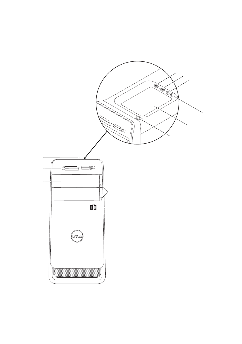
Front View of Your Computer
1
2
3
11
10
9
7
6
1
5
4
8
Technical Overview 18
Page 19
1 media-card reader light 2 media-card reader
1
2
3
4
5
6
7
8
9
11
10
3 optical-drive covers (2) 4 USB 3.0 ports (2)
5 optical-drive eject buttons (2) 6 power button
7 accessory tray 8 headphone port
9 microphone port 10 USB 2.0 port
11 USB 2.0 port with PowerShare
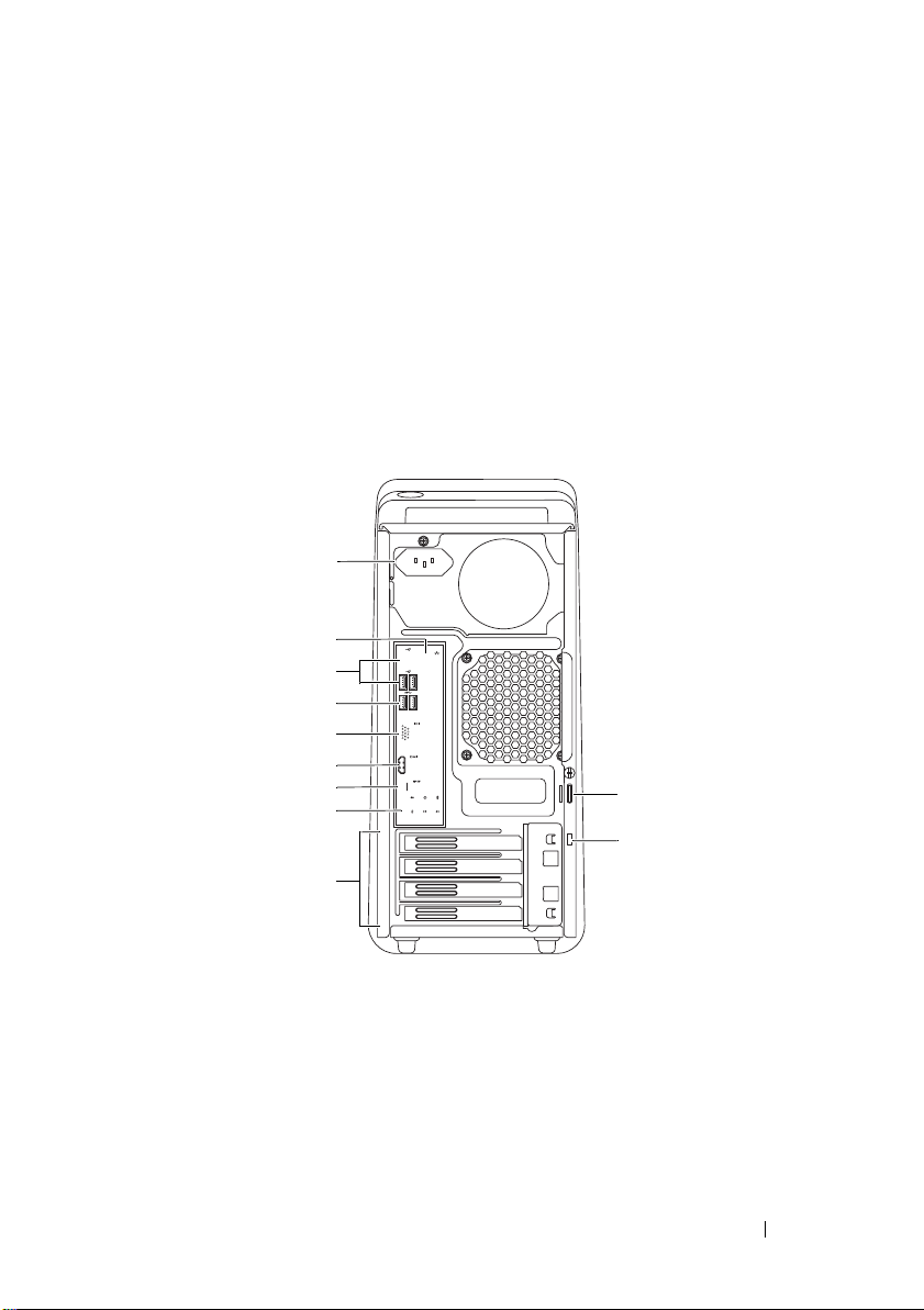
Back View of Your Computer
1 power port 2 network port
3 USB 2.0 ports (4) 4 USB 3.0 ports (2)
5 VGA port 6 HDMI port
7 optical S/P DIF port 8 audio ports
9 expansion-card slots 10 security-cable slot
11 padlock rings
Technical Overview
19
Page 20
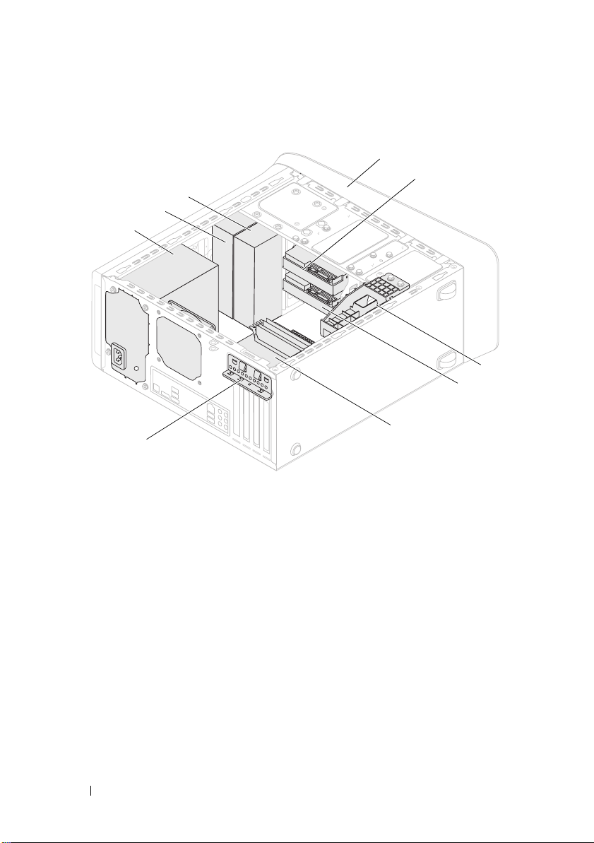
Inside View of Your Computer
9
8
7
6
1
front bezel
3
graphics-card bracket (optional)
5
system board
7
power supply
9
secondary optical-drive
2
primary hard-drive
4
secondary hard-drive
6
card retention clamp
8
primary optical-drive
1
2
3
4
5
20
Technical Overview
Page 21
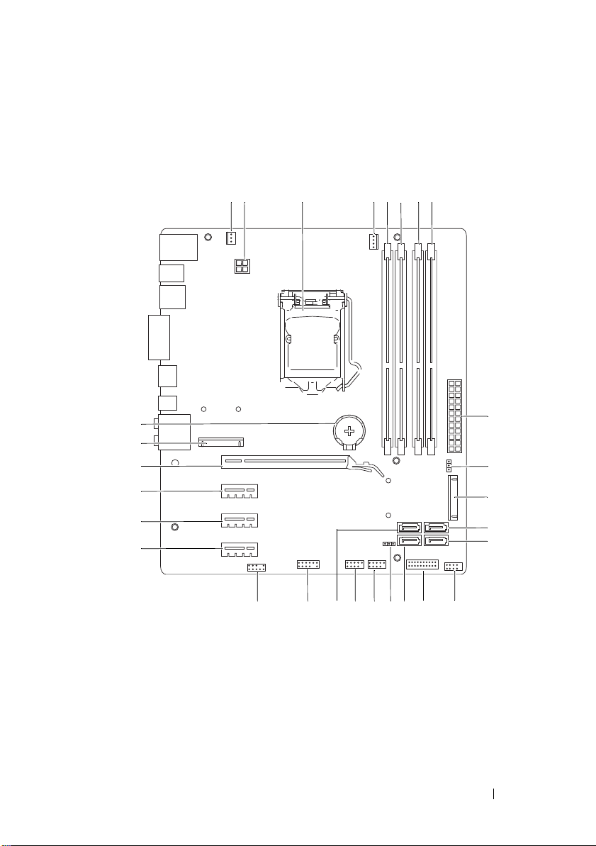
System-Board Components
1 2 3 4 5 6 7 8
22 21 20 19 18 17 16 15 14
28
27
26
25
24
23
9
10
11
12
13
Technical Overview 21
Page 22

1 chassis fan connector
(SYS_FAN 1)
3 processor socket 4 processor fan connector
5 memory module connector
(DIMM3)
7 memory module connector
(DIMM4)
9 main power connector
(PWR1)
mSATA slot (MSATA1)
11
SATA 2.0 (3 Gb/s) drive connector
13
(SATA 3)
15 front panel USB connector
(F_USB2)
17 CMOS reset jumper (RTCRST) 18 power button connector
19 front panel USB connector
(F_USB1)
21 front panel USB connector
(F_USB4)
23 PCI-Express x1 card slot
(PCI-EX1_3)
25 PCI-Express x1 card slot
(PCI-EX1_1)
27 Mini-Card slot
(PCIE_MINICARD)
2 power connector (PWR2)
(CPU_FAN)
6 memory module connector
(DIMM1)
8 memory module connector
(DIMM2)
10 password reset jumper (PSWD)
SATA 2.0 (3 Gb/s) drive connector
12
(SATA 2)
front panel USB connector
14
(F_USB3)
16 SATA 2.0 (3 Gb/s) drive connector
(SATA 1)
(F_PANEL)
20 SATA 3.0 (6 Gb/s) drive connector
(SATA 0)
22 front panel audio connector
(F_AUDIO1)
24 PCI-Express x1 card slot
(PCI-EX1_2)
26 PCI-Express x16 card slot
(PCI-EX16_1)
28 battery socket (BATTERY)
22
Technical Overview
Page 23
Computer Cover
WARNING: Before working inside your computer, read the safety information
that shipped with your computer and follow the steps in "Before You Begin" on
page 13. For additional safety best practices information, see the Regulatory
Compliance Homepage at dell.com/regulatory_compliance.
CAUTION: Ensure that sufficient space exists to support the computer with the
computer cover removed—at least 30 cm (1 ft.) of desk top space.
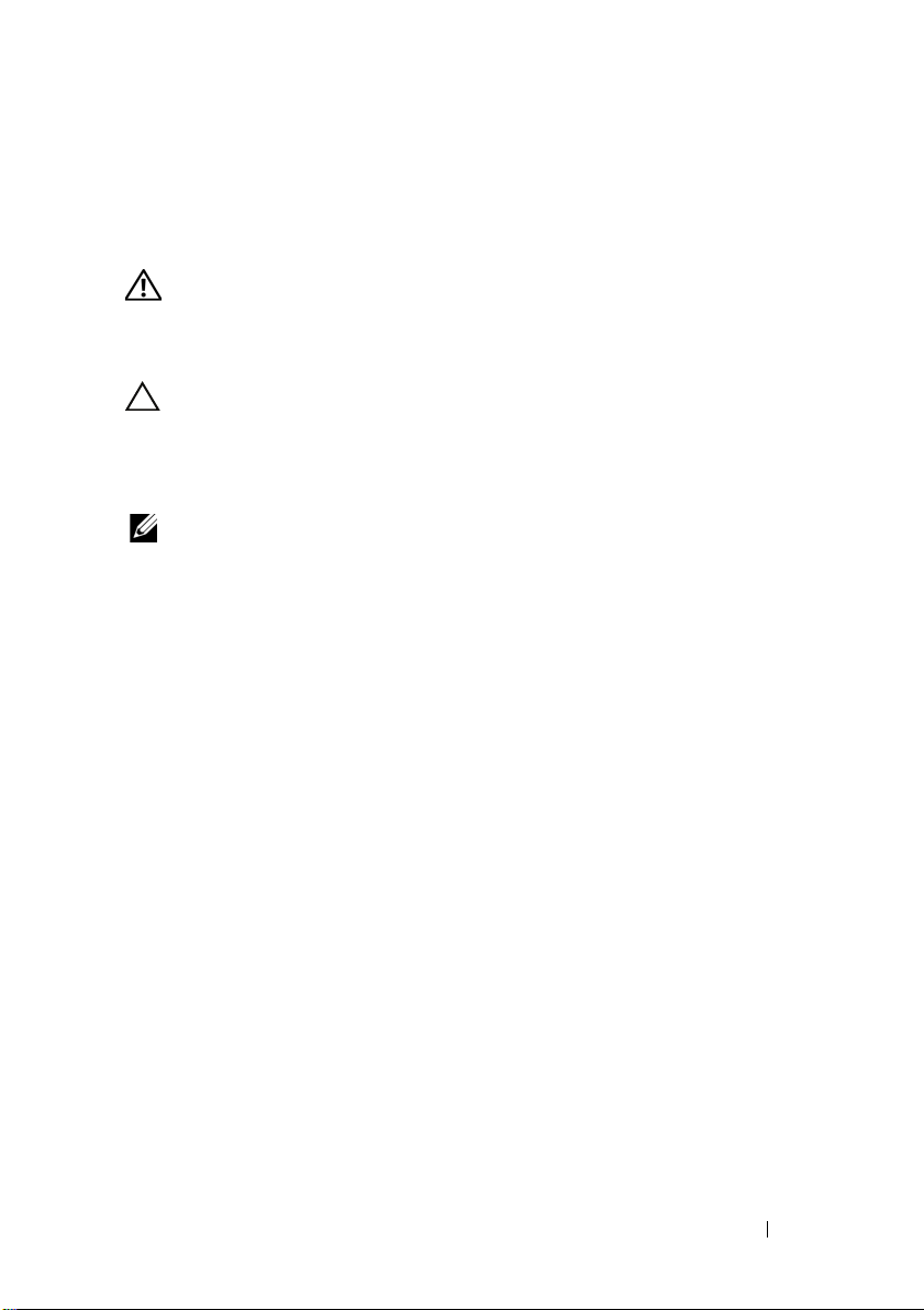
Removing the Computer Cover
NOTE: Ensure that you remove the security cable from the security cable slot (if
applicable).
1
Lay the computer on its side with the computer cover facing up.
2
Remove the thumbscrew that secures the computer cover to the chassis,
using a screw driver, if necessary.
3
Release the computer cover by sliding it away from the front of the
computer.
4
Lift the cover away from the computer and set it aside in a secure location.
4
Computer Cover 23
Page 24
1
2
1 thumbscrew 2 computer cover
24
Computer Cover
Page 25
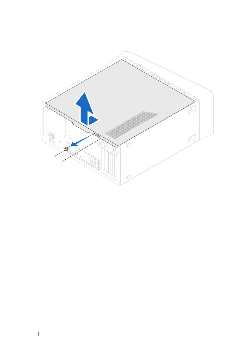
Replacing the Computer Cover
1
Connect all the cables and fold the cables out of the way.
2
3
4
5
Ensure that no tools or extra parts are left inside the computer.
Align the tabs at the bottom of the computer cover with the slots located
along the edge of the chassis.
Press the computer cover down and slide it towards the front of the computer.
Replace the thumbscrew that secures the computer cover to the chassis.
1
3
2
1 thumbscrew 2 slots
3 computer cover
6
Place the computer in an upright position.
7
Follow the steps in "After Working Inside Your Computer" on page 15.
Computer Cover 25
Page 26

26 Computer Cover
Page 27
Memory Module(s)
1
2
WARNING: Before working inside your computer, read the safety information
that shipped with your computer and follow the steps in "Before You Begin" on
page 13. For additional safety best practices information, see the Regulatory
Compliance Homepage at dell.com/regulatory_compliance.
Prerequisites
5
1
Remove the computer cover. See "Removing the Computer Cover" on
page 23.
Removing Memory Module(s)
WARNING: The memory module(s) may become very hot during normal operation.
Allow the memory module(s) to cool before touching them.
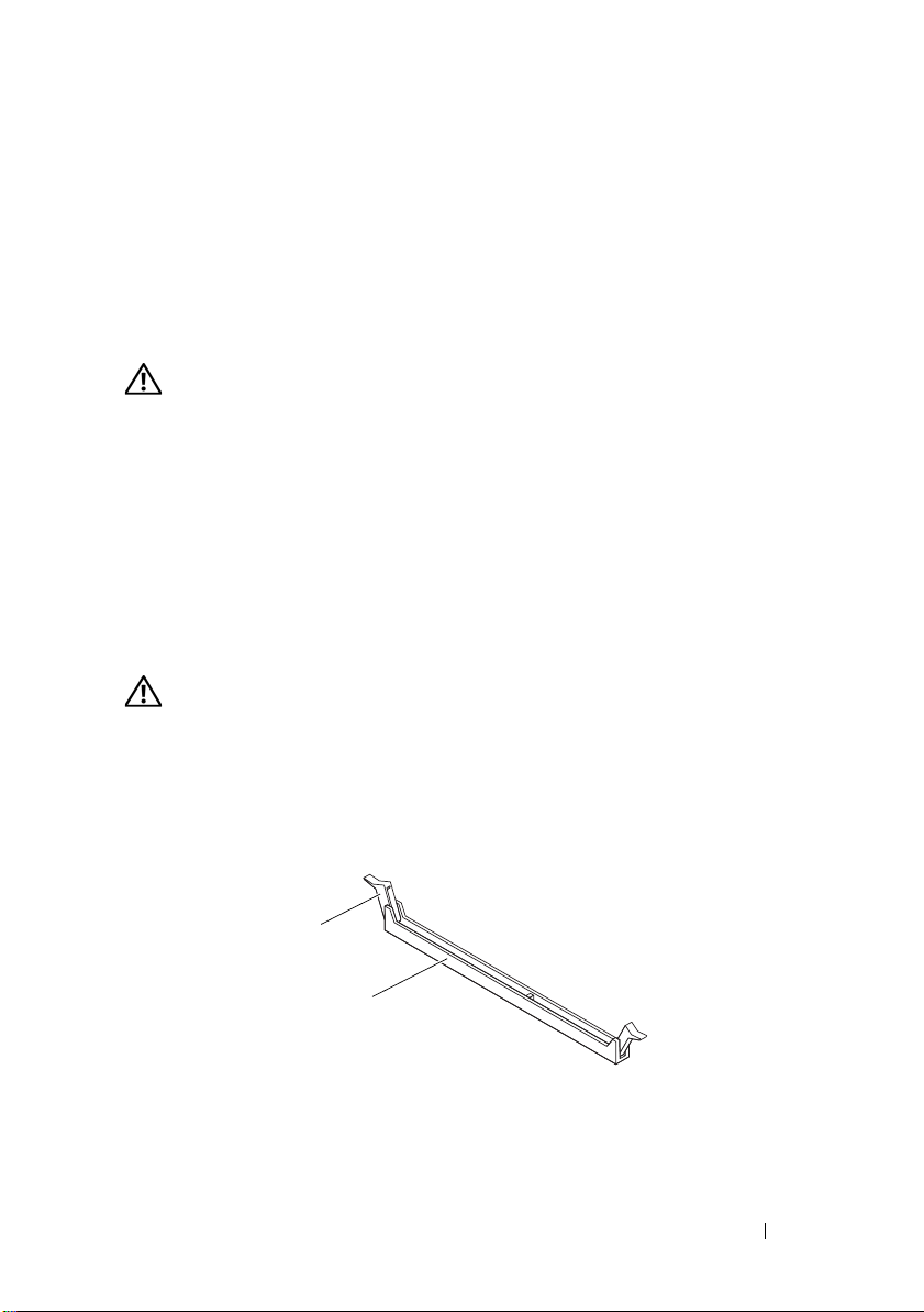
1
Push the securing clips away from the memory module.
2
Grasp the memory module and then gently ease the memory module out
of the memory-module connector.
1 securing clip 2 memory-module connector
Memory Module(s)
27
Page 28
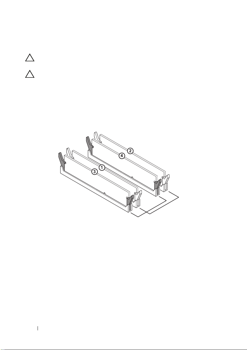
Replacing Memory Module(s)
CAUTION: If the memory module is not installed correctly, your computer may not
boot.
CAUTION: If you remove the original memory module(s) from your computer
during a memory upgrade, keep them separate from any new module(s) that you
may have, even if you purchased the new module(s) from Dell. If possible, do not
pair an original memory module with a new memory module. Otherwise, your
computer may not start properly. The recommended memory configurations are:
matched memory modules installed in DIMM connectors 1 and 2 and another
matched memory modules installed in DIMM connectors 3 and 4.
Recommended memory configuration:
Type
1600 MHz DDR3 Slots 1 and 2 or slots 1 through 4
Memory Module(s) 28
Slots
Page 29
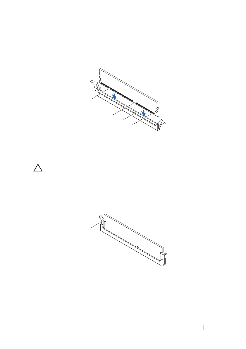
1
1
2
4
3
1
Align the notch on the bottom of the memory module with the tab on the
memory-module connector.
1 memory module 2 notch
3 tab 4 cutouts (2)
CAUTION: To avoid damage to the memory module, press the memory module
straight down into the connector while you apply equal force to each end of the
memory module.
2
Insert the memory module into the memory-module connector until the
memory module snaps into position and the securing clip locks in place.
securing clip (snapped in position)
1
Memory Module(s)
29
Page 30

Postrequisites
1
Replace the computer cover. See "Replacing the Computer Cover" on
page 25.
2
Follow the steps in "After Working Inside Your Computer" on page 15.
Memory Module(s) 30
Page 31

Front Bezel
WARNING: Before working inside your computer, read the safety information
that shipped with your computer and follow the steps in "Before You Begin" on
page 13. For additional safety best practices information, see the Regulatory
Compliance Homepage at dell.com/regulatory_compliance.
Prerequisites
6
1
Remove the computer cover. See "Removing the Computer Cover" on
page 23.
Removing the Front Bezel
1
Place the computer in an upright position.
2
Grasp and release the front bezel tabs sequentially, one at a time by moving
them outward from the front panel.
3
Rotate and pull the front bezel away from the front of the computer to
release the front bezel clamps from the front panel slots.
Front Bezel 31
Page 32

4
5
1 front bezel 2 front panel slots (3)
3 front bezel tabs (4) 4 front bezel clamps (3)
5 front panel
4
Set aside the front bezel in a secure location.
1
2
3
Front Bezel 32
Page 33

Replacing the Front Bezel
1
Align and insert the front bezel clamps into the front panel slots.
2
Rotate the front bezel towards the computer until the front bezel tabs
snap into place.
1
2
3
1 front bezel 2 front bezel tabs (4)
3 front panel slots (3) 4 front bezel clamps (3)
5 front panel
Front Bezel
4
5
33
Page 34

Postrequisites
1
Replace the computer cover. See "Replacing the Computer Cover" on
page 25.
2
Follow the steps in "After Working Inside Your Computer" on page 15.
Front Bezel 34
Page 35

7
Graphics-Card Bracket (optional)
WARNING: Before working inside your computer, read the safety information
that shipped with your computer and follow the steps in "Before You Begin" on
page 13. For additional safety best practices information, see the Regulatory
Compliance Homepage at dell.com/regulatory_compliance.
Prerequisites
1
Remove the computer cover. See "Removing the Computer Cover" on
page 23.
Removing the Graphics-Card Bracket
1
Remove the screws that secure the graphics-card bracket to the chassis.
2
Lift the graphics-card bracket off the chassis.
3
Set the graphics-card bracket aside in a secure location.
Graphics-Card Bracket (optional) 35
Page 36

1
1 screws (2) 2 graphics-card bracket
Replacing the Graphics-Card Bracket
1
Align the screw holes on the graphics-card bracket with the screw holes on
chassis.
2
Replace the screws that secure the graphics-card bracket to the chassis.
2
Postrequisites
1
Replace the computer cover. See "Replacing the Computer Cover" on
page 25.
2
Follow the steps in "After Working Inside Your Computer" on page 15.
Graphics-Card Bracket (optional) 36
Page 37

8
Graphics Card
WARNING: Before working inside your computer, read the safety information
that shipped with your computer and follow the steps in "Before You Begin" on
page 13. For additional safety best practices information, see the Regulatory
Compliance Homepage at dell.com/regulatory_compliance.
The system board of your computer is equipped with one PCI-Express x16
connector to install graphics card. To
the system board, see "System-Board Components
Prerequisites
locate the PCI-Express x16 connector on
" on page 21
.
1
Remove the computer cover. See "Removing the Computer Cover" on
page 23.
2
Remove the graphics-card bracket, if applicable. See "Removing the
Graphics-Card Bracket" on page 35.
Removing the Graphics Card
1
Remove the screw that secures the card-retention bracket to the chassis.
2
Lift the card-retention bracket and set it aside in a secure location.
Graphics Card 37
Page 38

1
2
1 screw 2 card-retention bracket
3
Locate the graphics card (PCI-Express x16 card) on the system board. See
"System-Board Components" on page 21.
NOTE: Your graphics card may have power-cable connectors.
4
Press the releasing clips on the power-cable connectors and disconnect the
power cable from the graphics card, if applicable.
NOTE: The appearance of the securing tab may be different on your
computer.
5
Press and hold the securing tab on the card connector, grasp the card by its
top corners, and then ease the card out of the card connector.
Graphics Card 38
Page 39

4
3
2
1
1 PCI-Express x16 connector 2 graphics card
3 securing tab 4 power cable
Replacing the Graphics Card
1
Align the graphics card with the PCI-Express x16 card connector on the
system board.
2
Place the card in the connector and press down firmly. Ensure that the card
is firmly seated in the slot.
3
Connect the power cable to the graphics card, if applicable.
4
Replace the card-retention bracket, ensuring that:
• The guide clamp is aligned with the guide notch.
• The top of all cards and filler brackets are flush with the alignment bar.
• The notch on top of the card or filler bracket fits around the
alignment guide.
Graphics Card 39
Page 40

5
2
3
Replace the screw that secures the card-retention bracket.
1
7
6
5
4
1
screw
3
card-retention bracket
5
alignment guide
7
guide notches (2)
40
Graphics Card
2
guide clamps (2)
4
alignment bar
6
filler bracket
Page 41

Postrequisites
1
Replace the graphics-card bracket, if applicable. See "Replacing the
Graphics-Card Bracket" on page 36.
2
Replace the computer cover. See "Replacing the Computer Cover" on
page 25.
3
Follow the steps in "After Working Inside Your Computer" on page 15.
Graphics Card 41
Page 42

42 Graphics Card
Page 43

PCI-Express x1 Card(s)
WARNING: Before working inside your computer, read the safety information
that shipped with your computer and follow the steps in "Before You Begin" on
page 13. For additional safety best practices information, see the Regulatory
Compliance Homepage at dell.com/regulatory_compliance.
Prerequisites
9
1
Remove the computer cover. See "Removing the Computer Cover" on
page 23.
2
Remove the graphics-card bracket, if applicable. See "Removing the
Graphics-Card Bracket" on page 35.
PCI-Express x1 Card(s) 43
Page 44

1
Removing the PCI-Express x1 Card(s)
1
Remove the screw that secures the card-retention bracket.
2
Lift the card-retention bracket and set it aside in a secure location.
2
1 screw 2 card-retention bracket
44
PCI-Express x1 Card(s)
Page 45

3
1
2
Locate the PCI-Express x1 card on the system board.
See "System-Board Components" on page 21.
4
Disconnect any cables connected to the card, if applicable.
5
Grasp the card by its top corners, and ease it out of its connector.
1 PCI-Express x1 card slot 2 PCI-Express x1 card
PCI-Express x1 Card(s)
45
Page 46

Replacing the PCI-Express x1 Card(s)
1
2
1
Place the PCI-Express x1 card in the slot on the system board and press
down firmly. Ensure that the PCI-Express x1 card is fully seated in the slot.
1 PCI-Express x1 card slot 2 PCI-Express x1 card
2
Replace the card-retention bracket, ensuring that:
• The guide clamp is aligned with the guide notch.
• The top of all cards and filler brackets are flush with the alignment bar.
• The notch on top of the card or filler bracket fits around the
alignment guide.
3
Replace the screw that secures the card-retention bracket.
PCI-Express x1 Card(s) 46
Page 47

1
2
3
1
screw
3
card-retention bracket
5
alignment guide
7
guide notches (2)
5
4
2
guide clamps (2)
4
alignment bar
6
filler bracket
7
6
PCI-Express x1 Card(s)
47
Page 48

Postrequisites
1
Replace the graphics-card bracket, if applicable. See "Replacing the
Graphics-Card Bracket" on page 36.
2
Replace the computer cover. See "Replacing the Computer Cover" on
page 25.
3
Follow the steps in "After Working Inside Your Computer" on page 15.
PCI-Express x1 Card(s) 48
Page 49

10
Wireless Mini-Card
WARNING: Before working inside your computer, read the safety information
that shipped with your computer and follow the steps in "Before You Begin" on
page 13. For additional safety best practices information, see the Regulatory
Compliance Homepage at dell.com/regulatory_compliance.
CAUTION: When the Mini-Card is not in the computer, store it in protective
antistatic packaging (see "Protecting Against Electrostatic Discharge" in the
safety instructions that shipped with your computer).
NOTE: Dell does not guarantee compatibility or provide support for Mini-Cards
from sources other than Dell.
If you ordered a wireless Mini-Card with your computer, the card is already
installed.
Your computer supports one half Mini-Card slot for Wireless Local Area
Network (WLAN) and Bluetooth combo card.
Prerequisites
1
Remove the computer cover. See "Removing the Computer Cover" on
page 23.
Wireless Mini-Card 49
Page 50

Removing the Mini-Card
1
2
3
5
4
1
Disconnect the antenna cable(s) from the Mini-Card.
2
Remove the screws that secure the Mini-Card to the system board.
1 screws (2) 2 tab
3 notch 4 Mini-Card
5 antenna cables (2)
3
Lift the Mini-Card away from the system-board connector.
Wireless Mini-Card 50
Page 51

Replacing the Mini-Card
CAUTION: The connectors are keyed to ensure correct insertion. Use of
excessive force may damage the connectors.
CAUTION: To avoid damage to the Mini-Card, ensure that there are no cables or
antenna cables under the Mini-Card.
1
Align the notch on the Mini-Card with the tab in the system-board
connector.
2
Insert the Mini-Card at a 45-degree angle into the system-board connector.
3
Press the other end of the Mini-Card down into the slot on the system
board and replace the screws that secure the Mini-Card to the system
board.
4
Connect the appropriate antenna cables to the Mini-Card you are
installing. The Mini-Card has two triangles marked on the label (black and
white):
• Connect the black cable to the connector marked with a black
triangle.
• Connect the white cable to the connector marked with a white
triangle.
Postrequisites
1
Replace the computer cover. See "Replacing the Computer Cover" on
page 25.
2
Follow the steps in "After Working Inside Your Computer" on page 15.
Wireless Mini-Card 51
Page 52

52 Wireless Mini-Card
Page 53

Mini-Card Antennas
WARNING: Before working inside your computer, read the safety information
that shipped with your computer and follow the steps in "Before You Begin" on
page 13. For additional safety best practices information, see the Regulatory
Compliance Homepage at dell.com/regulatory_compliance.
Prerequisites
11
1
Remove the computer cover. See "Removing the Computer Cover" on
page 23.
2
Remove the front bezel. See "Removing the Front Bezel" on page 31.
3
Remove the top cover. See "Removing the Top Cover" on page 77.
Removing the Mini-Card Antennas
1
Disconnect the Mini-Card antenna cable(s) from the Mini-Card.
2
Make note of the Mini-Card antenna-cable routing and remove the cables
from the routing guides.
3
Remove the screws that secure the Mini-Card antennas to the top panel.
4
Lift the Mini-Card antennas to release them from the top panel.
Mini-Card Antennas 53
Page 54

1
2
3
4
1 Mini-Card antennas (2) 2 screws (4)
3 Mini-Card antenna cables 4 top panel
54
Mini-Card Antennas
Page 55

Replacing the Mini-Card Antennas
1
Place the Mini-Card antennas in position and replace the screws that
secure the Mini-Card antennas to the top panel.
2
Route the Mini-Card antenna cables through the routing guides.
3
Connect the appropriate antenna cables to the WLAN card you are
installing. The WLAN card has two triangles marked on the label (black
and white):
• Connect the black cable to the connector marked with a black
triangle.
• Connect the white cable to the connector marked with a white
triangle.
Postrequisites
1
Replace the top cover. See "Replacing the Top Cover" on page 78.
2
Replace the front bezel. See "Replacing the Front Bezel" on page 33.
3
Replace the computer cover. See "Replacing the Computer Cover" on
page 25.
4
Follow the steps in "After Working Inside Your Computer" on page 15.
Mini-Card Antennas 55
Page 56

56 Mini-Card Antennas
Page 57

mSATA Drive
WARNING: Before working inside your computer, read the safety information
that shipped with your computer and follow the steps in "Before You Begin" on
page 13. For additional safety best practices information, see the Regulatory
Compliance Homepage at dell.com/regulatory_compliance.
Prerequisites
12
1
Remove the computer cover. See "Removing the Computer Cover" on
page 23.
Removing the mSATA Drive
1
Locate the mSATA slot (MSATA1) on the system board. See
"System-Board Components" on page 21.
2
Remove the screws that secure the mSATA drive to the system board.
3
Lift the mSATA drive away from the system-board connector.
mSATA Drive 57
Page 58

2
1
3
4
1 mSATA drive 2 screws (2)
3 notch 4 tab
Replacing the mSATA Drive
CAUTION: The connectors are keyed to ensure correct insertion. Use of
excessive force may damage the connectors.
CAUTION: To avoid damage to the mSATA drive, ensure that there are no cables
under the mSATA drive.
1
Align the notch on the mSATA drive with the tab in the system-board
connector.
2
Insert the mSATA drive at a 45-degree angle into the system-board
connector.
3
Press the other end of the mSATA drive down into the slot on the system
board and replace the screws that secure the mSATA drive to the system
board.
mSATA Drive 58
Page 59

Postrequisites
1
Replace the computer cover. See "Replacing the Computer Cover" on
page 25.
2
Follow the steps in "After Working Inside Your Computer" on page 15.
mSATA Drive 59
Page 60

60 mSATA Drive
Page 61

13
Hard Drive(s)
WARNING: Before working inside your computer, read the safety information
that shipped with your computer and follow the steps in "Before You Begin" on
page 13. For additional safety best practices information, see the Regulatory
Compliance Homepage at dell.com/regulatory_compliance.
WARNING: If you remove the hard drive from the computer when the drive is hot,
do not touch
CAUTION: To avoid data loss, do not remove the hard drive while the computer is
on or in Sleep state.
CAUTION: Hard drives are extremely fragile. Exercise care when handling the
hard drive.
the metal housing of the hard drive.
Primary Hard-Drive
Prerequisites
1
Remove the computer cover. See "Removing the Computer Cover" on
page 23.
Removing the Primary Hard-Drive
1
Disconnect the power and data cables from the primary hard-drive.
2
Remove the screws that secure the hard drive to the chassis.
3
Slide the hard drive out towards the back of the computer.
Hard Drive(s) 61
Page 62

3
2
1
4
1 power cable 2 data cable
3 screws (4) 4 primary hard-drive
Replacing the Primary Hard-Drive
1
Slide the primary hard-drive into the hard drive cage.
2
Align the screw holes on the primary hard-drive with the screw holes on the
chassis.
3
Replace the screws that secure the primary hard-drive to the chassis.
4
Connect the power and data cables to the primary hard-drive.
Postrequisites
1
Replace the computer cover. See "Replacing the Computer Cover" on
page 25.
2
Follow the steps in "After Working Inside Your Computer" on page 15.
Hard Drive(s) 62
Page 63

Hard Drive Cage
Prerequisites
1
Remove the computer cover. See "Removing the Computer Cover" on
page 23.
2
Remove the primary hard-drive. See "Removing the Primary Hard-Drive"
on page 61.
Removing the Hard Drive Cage
1
If applicable, disconnect the power and data cables from the secondary
hard-drive.
2
Remove the screws that secure the hard drive cage to the chassis.
3
Slide the hard drive cage towards the back of the chassis.
Hard Drive(s) 63
Page 64

3
2
1
4
5
1 power cable 2 data cable
3 screws (3) 4 hard drive cage
5 secondary hard-drive
Replacing the Hard Drive Cage
1
Align the screw holes on the hard drive cage with the screw holes on the
chassis.
2
Replace the screws that secure the hard drive cage to the chassis.
3
If applicable, connect the power and data cables to the secondary hard-drive.
Hard Drive(s) 64
Page 65

Postrequisites
1
Replace the primary hard-drive. See "Replacing the Primary Hard-Drive"
on page 62.
2
Replace the computer cover. See "Replacing the Computer Cover" on
page 25.
Secondary Hard-Drive (optional)
Prerequisites
1
Remove the computer cover. See "Removing the Computer Cover" on
page 23.
2
Remove the primary hard-drive. See "Removing the Primary Hard-Drive"
on page 61.
3
Remove the hard drive cage. See "Removing the Hard Drive Cage" on
page 63.
Removing the Secondary Hard-Drive
1
Remove the screws that secure the secondary hard-drive to the hard drive
cage.
2
Slide the secondary hard-drive away from the hard drive cage.
Hard Drive(s) 65
Page 66

1
3
2
1 secondary hard-drive 2 screws (4)
3 hard drive cage
Replacing the Secondary Hard-Drive
1
Slide the secondary hard-drive into the hard drive cage.
2
Align the screw holes on the secondary hard-drive with the screw holes on
the hard drive cage.
3
Replace the screws that secure the secondary hard-drive to the hard drive
cage.
Postrequisites
1
Replace the hard drive cage. See "Replacing the Hard Drive Cage" on
page 64.
2
Replace the primary hard-drive. See "Replacing the Primary Hard-Drive"
on page 62.
3
Replace the computer cover. See "Replacing the Computer Cover" on
page 25.
Hard Drive(s) 66
Page 67

Optical Drive(s)
WARNING: Before working inside your computer, read the safety information
that shipped with your computer and follow the steps in "Before You Begin" on
page 13. For additional safety best practices information, see the Regulatory
Compliance Homepage at dell.com/regulatory_compliance.
Prerequisites
14
1
Remove the computer cover. See "Removing the Computer Cover" on
page 23.
2
Remove the front bezel. See "Removing the Front Bezel" on page 31.
Removing the Optical Drive
1
Disconnect the power and data cables from the optical drive.
2
Remove the screws that secure the optical drive to the chassis.
Optical Drive(s) 67
Page 68

3
Push and slide the optical drive out through the front of the computer.
NOTE: Repeat steps 1 to 3 to remove secondary optical-drive, if applicable.
3
4
2
1
1 power cable 2 data cable
3 screws (2) 4 optical drive
4
Set aside the optical drive in a secure location.
Optical Drive(s) 68
Page 69

Replacing the Optical Drive
1
Gently slide the optical drive into the optical-drive bay through the front
of the computer.
2
Align the screw holes on the optical drive with the screw holes on the
chassis.
3
Replace the screws that secure the optical drive to the chassis.
4
Connect the power and data cables to the optical drive.
Postrequisites
1
Replace the computer cover. See "Replacing the Computer Cover" on
page 25.
2
Replace the front bezel. See "Replacing the Front Bezel" on page 33.
Secondary Optical-Drive
Prerequisites
1
Remove the computer cover. See "Removing the Computer Cover" on
page 23.
2
Remove the front bezel. See "Removing the Front Bezel" on page 31.
Optical Drive(s) 69
Page 70

Installing a Secondary Optical-Drive
1
Insert a screw driver and twist it to remove the break-away metal plate.
2
Pull the break-away metal plate away from the chassis.
1
1 break-away metal plate
3 4 Gently slide the secondary optical-drive into the optical-drive bay through
the front of the computer.
Align the screw holes on the secondary optical-drive with the screw holes
on the chassis.
5
Replace the two screws that secure the secondary optical-drive to the
chassis.
6
Connect the power and data cables to the secondary optical-drive.
Optical Drive(s) 70
Page 71

Postrequisites
1
Replace the computer cover. See "Replacing the Computer Cover" on
page 25.
2
Replace the front bezel. See "Replacing the Front Bezel" on page 33.
Optical Drive(s) 71
Page 72

72 Optical Drive(s)
Page 73

Media-Card Reader
WARNING: Before working inside your computer, read the safety information
that shipped with your computer and follow the steps in "Before You Begin" on
page 13. For additional safety best practices information, see the Regulatory
Compliance Homepage at dell.com/regulatory_compliance.
Prerequisites
15
1
Remove the computer cover. See "Removing the Computer Cover" on
page 23.
2
Remove the front bezel. See "Removing the Front Bezel" on page 31.
3
Remove the optical drive. See "Removing the Optical Drive" on page 67.
4
Remove the top cover. See "Removing the Top Cover" on page 77.
Media-Card Reader 73
Page 74

Removing the Media-Card Reader
1
Remove the screws that secure the Media-Card Reader to the front panel.
The screws are located below the Media-Card Reader.
2
Disconnect the Media-Card Reader cable from the system board
connector F_USB1. See "System-Board Components" on page 21.
3
Slide and lift the Media-Card Reader to remove it from the top panel.
1
2
3
4
5
6
Media-Card Reader 74
Page 75

1 Media-Card Reader guides (2) 2 slots (2)
3 top panel 4 Media-Card Reader
5 screws (2) 6 front panel
Replacing the Media-Card Reader
1
Gently slide the Media-Card Reader guides into the slots in the top panel.
2
Replace the screws that secure the Media-Card Reader to the front panel.
3
Connect the Media-Card Reader cable to the system board connector
F_USB1. See "System-Board Components" on page 21.
Postrequisites
1
Replace the top cover. See "Replacing the Top Cover" on page 78.
2
Replace the optical drive. See "Replacing the Optical Drive" on page 69.
3
Replace the front bezel. See "Replacing the Front Bezel" on page 33.
4
Replace the computer cover. See "Replacing the Computer Cover" on
page 25.
5
Follow the steps in "After Working Inside Your Computer" on page 15.
Media-Card Reader 75
Page 76

76 Media-Card Reader
Page 77

Top Cover
WARNING: Before working inside your computer, read the safety information
that shipped with your computer and follow the steps in "Before You Begin" on
page 13. For additional safety best practices information, see the Regulatory
Compliance Homepage at dell.com/regulatory_compliance.
Prerequisites
16
1
Remove the computer cover. See "Removing the Computer Cover" on
page 23.
2
Remove the front bezel. See "Removing the Front Bezel" on page 31.
3
Remove the optical drive. See "Removing the Optical Drive" on page 67.
Removing the Top Cover
1
Pull the release tab, and slide the top cover towards the front of the
computer to release the top-cover tabs from the slots on the top panel.
2
Pull the top cover away from the top panel.
3
Set the top cover aside in a secure location.
Top Cover 77
Page 78

5
4
3
2
1
1 slots 2
3 top-cover tabs 4
5 top cover
release tab
top panel
Replacing the Top Cover
1
Align the tabs on the top cover with the slots on the top panel.
2
Press and slide the top cover towards the back of the computer, until it
clicks into place.
Top Cover 78
Page 79

Postrequisites
1
Replace the optical drive. See "Replacing the Optical Drive" on page 69.
2
Replace the front bezel. See "Replacing the Front Bezel" on page 33.
3
Replace the computer cover. See "Replacing the Computer Cover" on
page 25.
4
Follow the steps in "After Working Inside Your Computer" on page 15.
Top Cover 79
Page 80

80 Top Cover
Page 81

Top I/O Panel
WARNING: Before working inside your computer, read the safety information
that shipped with your computer and follow the steps in "Before You Begin" on
page 13. For additional safety best practices information, see the Regulatory
Compliance Homepage at dell.com/regulatory_compliance.
Prerequisites
17
1
Remove the computer cover. See "Removing the Computer Cover" on
page 23.
2
Remove the front bezel. See "Removing the Front Bezel" on page 31.
3
Remove the optical drive. See "Removing the Optical Drive" on page 67.
4
Remove the top cover. See "Removing the Top Cover" on page 77.
Removing the Top I/O Panel
1
Disconnect the top I/O panel cables from the system board connectors,
F_USB3 and F_AUDIO1. See "System-Board Components" on page 21.
2
Remove the screws that secure the top I/O panel to the top panel.
3
Carefully remove the top I/O panel from the top panel.
Top I/O Panel 81
Page 82

1
2
3
1 screws (2) 2 top I/O panel
3 top panel
82
Top I/O Panel
Page 83

Replacing the Top I/O Panel
1
Align the screw holes on the top I/O panel with the screw holes on the top
panel.
2
Replace the screws that secure the top I/O panel to the top panel.
3
Connect the top I/O panel cables to the system board connectors, F_USB3
and F_AUDIO1. See "System-Board Components" on page 21.
Postrequisites
1
Replace the top cover. See "Replacing the Top Cover" on page 78.
2
Replace the optical drive. See "Replacing the Optical Drive" on page 69.
3
Replace the front bezel. See "Replacing the Front Bezel" on page 33.
4
Replace the computer cover. See "Replacing the Computer Cover" on
page 25.
5
Follow the steps in "After Working Inside Your Computer" on page 15.
Top I/O Panel 83
Page 84

84 Top I/O Panel
Page 85

Front USB Panel
WARNING: Before working inside your computer, read the safety information
that shipped with your computer and follow the steps in "Before You Begin" on
page 13. For additional safety best practices information, see the Regulatory
Compliance Homepage at dell.com/regulatory_compliance.
Prerequisites
18
1
Remove the computer cover. See "Removing the Computer Cover" on
page 23.
2
Remove the front bezel. See "Removing the Front Bezel" on page 31.
Removing the Front USB Panel
CAUTION: When sliding the front USB panel out of the computer, be extremely
careful. Carelessness may result in damage to the cable connectors and the cable
routing clips.
NOTE: Note the routing of all cables as you remove them so that you can
re-route them correctly after you replace the front USB panel.
1
Disconnect the front USB panel cables from the system board connector
F_USB2. See "System-Board Components" on page 21.
2
Remove the screw that secures the front USB panel to the front panel.
3
Slide the front USB panel down to release the clamps from the front panel
and pull it away.
Front USB Panel 85
Page 86

1
2
3
4
1 front USB panel clamp slot 2 clamps (2)
3 front USB panel 4 screw
Replacing the Front USB Panel
1
Align and slide the front USB panel clamps into the front USB panel
clamp slot.
2
Replace the screw that secures the front USB panel to the front panel.
3
Connect the front USB panel cables to the system board connector
F_USB2. See "System-Board Components" on page 21.
Front USB Panel 86
Page 87

Postrequisites
1
Replace the front bezel. See "Replacing the Front Bezel" on page 33.
2
Replace the computer cover. See "Replacing the Computer Cover" on
page 25.
3
Follow the steps in "After Working Inside Your Computer" on page 15.
Front USB Panel 87
Page 88

88 Front USB Panel
Page 89

Power Button Module
WARNING: Before working inside your computer, read the safety information
that shipped with your computer and follow the steps in "Before You Begin" on
page 13. For additional safety best practices information, see the Regulatory
Compliance Homepage at dell.com/regulatory_compliance.
Prerequisites
19
1
Remove the computer cover. See "Removing the Computer Cover" on
page 23.
2
Remove the front bezel. See "Removing the Front Bezel" on page 31.
3
Remove the optical drive. See "Removing the Optical Drive" on page 67.
4
Remove the top cover. See "Removing the Top Cover" on page 77.
Power Button Module 89
Page 90

Removing the Power Button Module
1
Disconnect the power button module cable from the system board
connector, F_PANEL. See "System-Board Components" on page 21.
2
Press the power button module tabs and lift the power button module to
release it from the top panel.
1
2
3
1 cable 2 power button module
3 power button module tabs (4) 4 slot
90 Power Button Module
4
Page 91

Replacing the Power Button Module
1
Align and push the power button module tabs into the slots on the top
panel.
2
Connect the power button module cable to the system board connector,
F_PANEL. See "System-Board Components" on page 21.
Postrequisites
1
Replace the top cover. See "Replacing the Top Cover" on page 78.
2
Replace the optical drive. See "Replacing the Optical Drive" on page 69.
3
Replace the front bezel. See "Replacing the Front Bezel" on page 33.
4
Replace the computer cover. See "Replacing the Computer Cover" on
page 25.
5
Follow the steps in "After Working Inside Your Computer" on page 15.
Power Button Module 91
Page 92

92 Power Button Module
Page 93

Chassis Fan
WARNING: Before working inside your computer, read the safety information
that shipped with your computer and follow the steps in "Before You Begin" on
page 13. For additional safety best practices information, see the Regulatory
Compliance Homepage at dell.com/regulatory_compliance.
Prerequisites
1
Remove the computer cover. See "Removing the Computer Cover" on
page 23.
Chassis Fan 93
Page 94

Removing the Chassis Fan
1
Disconnect the chassis fan cable from the system board connector
SYS_FAN1. See "System-Board Components" on page 21.
2
Remove the screws that secure the chassis fan to the chassis.
3
Slide and lift the chassis fan away from the computer as shown in the
illustration.
2
1
1 screws (4) 2 chassis fan
94
Chassis Fan
Page 95

Replacing the Chassis Fan
1
Align the screw holes on the chassis fan with the screw holes on the chassis.
2
Replace the screws that secure the chassis fan to the chassis.
3
Connect the chassis fan cable to the system board connector SYS_FAN1.
See "System-Board Components" on page 21.
Postrequisites
1
Replace the computer cover. See "Replacing the Computer Cover" on
page 25.
2
Follow the steps in "After Working Inside Your Computer" on page 15.
Chassis Fan 95
Page 96

96 Chassis Fan
Page 97

Processor Fan and Heat-Sink Assembly
WARNING: Before working inside your computer, read the safety information
that shipped with your computer and follow the steps in "Before You Begin" on
page 13. For additional safety best practices information, see the Regulatory
Compliance Homepage at dell.com/regulatory_compliance.
WARNING: The heat sink may be very hot during normal operation. Provide
sufficient time for the heat-sink to cool before you touch it.
Prerequisites
21
1
Remove the computer cover. See "Removing the Computer Cover" on
page 23.
Removing the Processor Fan and Heat-Sink Assembly
WARNING: Despite having a plastic shield, the processor fan and heat-sink
assembly may be very hot during normal operation. Ensure that it has had
sufficient time to cool before you touch it.
CAUTION: To ensure maximum cooling for the processor, do not touch the heat
transfer areas on the processor fan and heat-sink assembly. The oils in your skin
can reduce the heat transfer capability of the thermal grease.
CAUTION: The processor fan and heat-sink assembly is a single unit. Do not try to
remove the fan separately.
1
Disconnect the processor fan cable from the system board connector,
CPU_FAN. See "System-Board Components" on page 21.
2
Using a flat-blade screwdriver loosen the four captive screws that secure
the processor fan and heat-sink assembly to the system board.
Processor Fan and Heat-Sink Assembly 97
Page 98

3
Lift the processor fan and heat-sink assembly out of the computer.
1
2
1 processor fan and heat-sink assembly 2 processor fan cable
3captive screws (4)
3
98
Processor Fan and Heat-Sink Assembly
Page 99

Replacing the Processor Fan and Heat-Sink Assembly
1
Clean the thermal grease from the bottom of the heat-sink.
2
Apply new thermal grease to the top of the processor, if applicable.
3
Place the processor fan and heat-sink assembly over the processor.
4
Align the captive screws on the processor fan and heat-sink assembly with
the screw holes on the system board.
5
Tighten the captive screws that secure the processor fan and heat-sink
assembly to the system board.
6
Connect the processor fan cable to the system board connector,
CPU_FAN. See "System-Board Components" on page 21.
Postrequisites
1
Replace the computer cover. See "Replacing the Computer Cover" on
page 25.
2
Follow the steps in "After Working Inside Your Computer" on page 15.
Processor Fan and Heat-Sink Assembly 99
Page 100

100 Processor Fan and Heat-Sink Assembly
 Loading...