

Page 1

OptiPlex 7080 Micro
Setup and specifications guide
Regulatory Model: D14U
Regulatory Type: D14U001/D14U003
May 2020
Rev. A00
Page 2

Notes, cautions, and warnings
NOTE: A NOTE indicates important information that helps you make better use of your product.
CAUTION: A CAUTION indicates either potential damage to hardware or loss of data and tells you how to avoid the
problem.
WARNING: A WARNING indicates a potential for property damage, personal injury, or death.
© 2020 Dell Inc. or its subsidiaries. All rights reserved. Dell, EMC, and other trademarks are trademarks of Dell Inc. or its subsidiaries. Other
trademarks may be trademarks of their respective owners.
Page 3

Contents
1 Set up your computer................................................................................................................... 5
2 Chassis overview........................................................................................................................ 10
Front view............................................................................................................................................................................. 10
Back view...............................................................................................................................................................................11
System board Layout...........................................................................................................................................................13
3 Technical specifications.............................................................................................................. 14
Dimensions and weight........................................................................................................................................................14
Chipset...................................................................................................................................................................................14
Processors............................................................................................................................................................................ 15
Operating system.................................................................................................................................................................16
Memory..................................................................................................................................................................................17
Intel Optane memory (optional)......................................................................................................................................... 17
Ports and connectors.......................................................................................................................................................... 18
Communications...................................................................................................................................................................19
Graphics and Video controller............................................................................................................................................20
Audio and Speaker...............................................................................................................................................................20
Storage................................................................................................................................................................................. 20
Power adapter...................................................................................................................................................................... 21
Add-in cards..........................................................................................................................................................................21
Data security........................................................................................................................................................................ 22
Environmental...................................................................................................................................................................... 22
Energy Star and Trusted Platform Module (TPM)......................................................................................................... 22
Computer environment.......................................................................................................................................................23
Service and support............................................................................................................................................................ 23
4 Software................................................................................................................................... 25
Downloading Windows drivers...........................................................................................................................................25
5 System setup.............................................................................................................................26
Boot menu............................................................................................................................................................................26
Navigation keys....................................................................................................................................................................26
Boot Sequence.....................................................................................................................................................................27
System setup options..........................................................................................................................................................27
General options.............................................................................................................................................................. 27
System information....................................................................................................................................................... 28
Video screen options.....................................................................................................................................................29
Security...........................................................................................................................................................................29
Secure boot options...................................................................................................................................................... 30
Intel Software Guard Extensions options....................................................................................................................31
Performance................................................................................................................................................................... 31
Power management...................................................................................................................................................... 32
Post behavior................................................................................................................................................................. 33
Contents 3
Page 4

Manageability................................................................................................................................................................. 33
Virtualization support.................................................................................................................................................... 34
Wireless options.............................................................................................................................................................34
Maintenance...................................................................................................................................................................34
System logs.................................................................................................................................................................... 35
Advanced configuration................................................................................................................................................35
SupportAssist System Resolution............................................................................................................................... 35
Updating the BIOS in Windows ........................................................................................................................................ 35
Updating BIOS on systems with BitLocker enabled..................................................................................................36
Updating your system BIOS using a USB flash drive................................................................................................36
System and setup password.............................................................................................................................................. 37
Assigning a system setup password............................................................................................................................37
Deleting or changing an existing system setup password........................................................................................38
6 Getting help...............................................................................................................................39
Contacting Dell.................................................................................................................................................................... 39
4 Contents
Page 5

Steps
1. Connect the keyboard and mouse.
1
Set up your computer
2. Connect to your network using a cable, or connect to a wireless network.
Set up your computer 5
Page 6
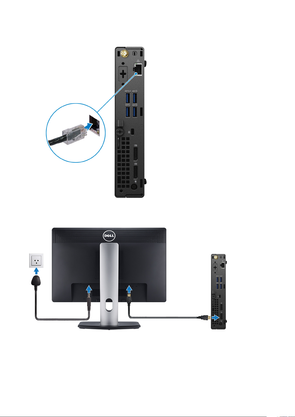
3. Connect the display.
4. Connect the power cable.
6
Set up your computer
Page 7
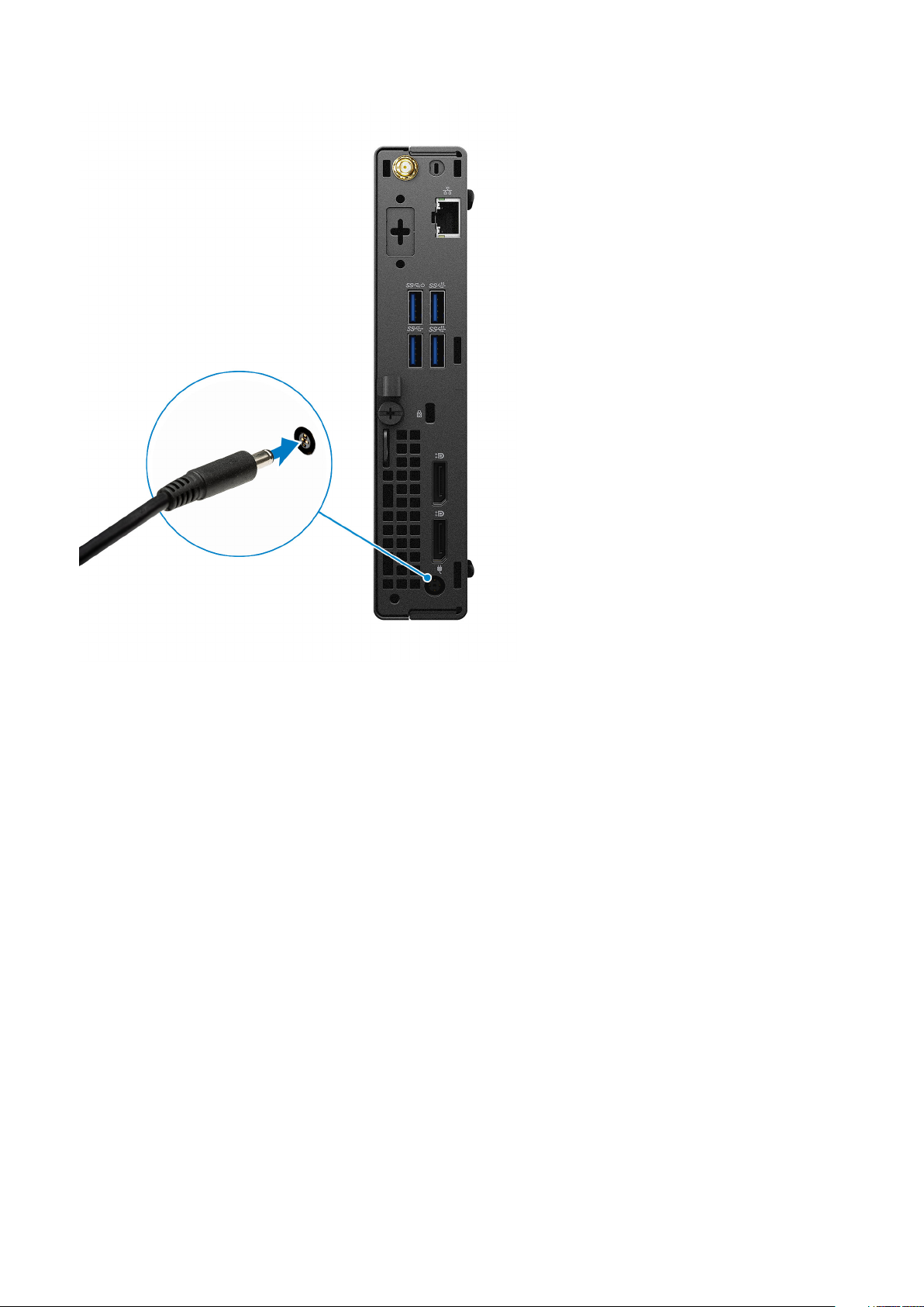
5. Press the power button.
Set up your computer
7
Page 8
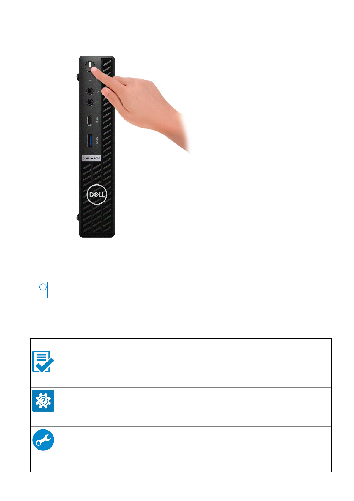
6. Finish Windows system setup.
Follow the on-screen instructions to complete the setup. When setting up, Dell recommends that you:
• Connect to a network for Windows updates.
NOTE:
If connecting to a secured wireless network, enter the password for the wireless network access when
prompted.
• If connected to the internet, sign-in with or create a Microsoft account. If not connected to the internet, create an offline account.
• On the Support and Protection screen, enter your contact details.
7. Locate and use Dell apps from the Windows Start menu—Recommended.
Table 1. Locate Dell apps
Dell apps Details
Dell Product Registration
Register your computer with Dell.
Dell Help & Support
Access help and support for your computer.
8 Set up your computer
SupportAssist
Proactively checks the health of your computer’s hardware and
software.
Page 9

Table 1. Locate Dell apps(continued)
Dell apps Details
Dell Update
Updates your computer with critical fixes and important device
drivers as they become available.
Dell Digital Delivery
Download software applications including software that is
purchased but not preinstalled on your computer.
NOTE: Renew or upgrade your warranty by clicking the
warranty expiry date in SupportAssist.
Set up your computer 9
Page 10
Topics:
• Front view
• Back view
• System board Layout
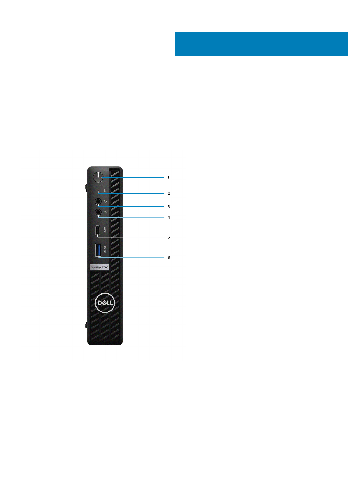
Front view
2
Chassis overview
1. Power button with diagnostic LED
2. Hard-disk drive activity light
3. Universal audio jack port
4. Line-out port (retaskable Line-in)
5. USB 3.2 Gen 2 Type-C port
6. USB 3.2 Gen 2 Type-A port with PowerShare
10 Chassis overview
Page 11
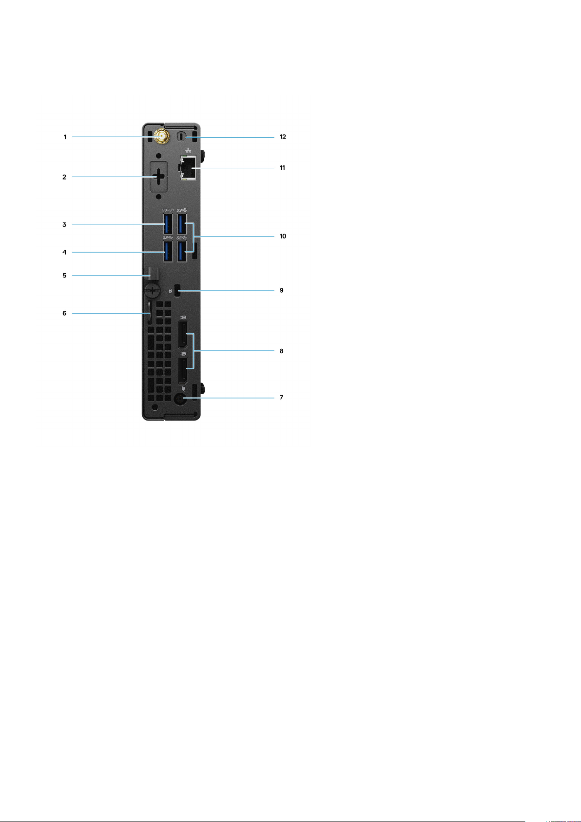
Back view
1.
External antenna connector
2. Serial/Video Port (Serial/PS2/DP 1.4/HDMI 2.0/VGA/USB 3.2 Gen 2 Type-C with DP Alt Mode) (optional)
3. USB 3.2 Gen 1 Type-A port with Smart Power on
4. USB 3.2 Gen 1 Type-A port
5. Cable holder
6. Padlock ring
7. Power connector port
8. DisplayPort 1.4 (2)
9. Kensington security-cable slot
10. USB 3.2 Gen 2 Type-A ports (2)
11. RJ-45 port 10/100/1000 Mbps
12. External antenna connector port
Chassis overview
11
Page 12
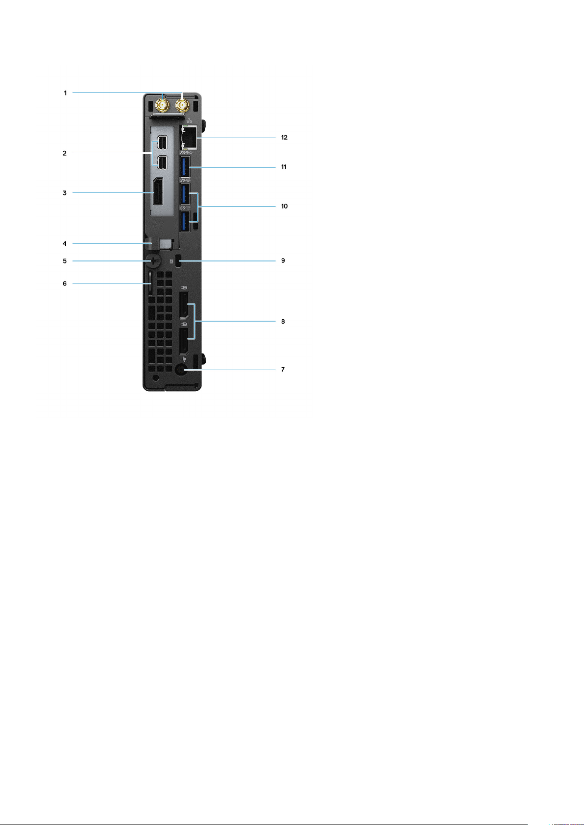
1. External antenna connectors
2. Mini DisplayPort (2) (With Radeon RX 640)
3. DisplayPort 1.4 (With Radeon RX 640)
4. Cable holder
5. Thumbscrew
6. Padlock ring
7. Power connector port
8. DisplayPort 1.4 (2)
9. Kensington security-cable slot
10. USB 3.2 Gen 2 Type-A ports (2)
11. USB 3.2 Gen 1 Type-A port with Smart Power on
12. RJ-45 port 10/100/1000 Mbps
12
Chassis overview
Page 13
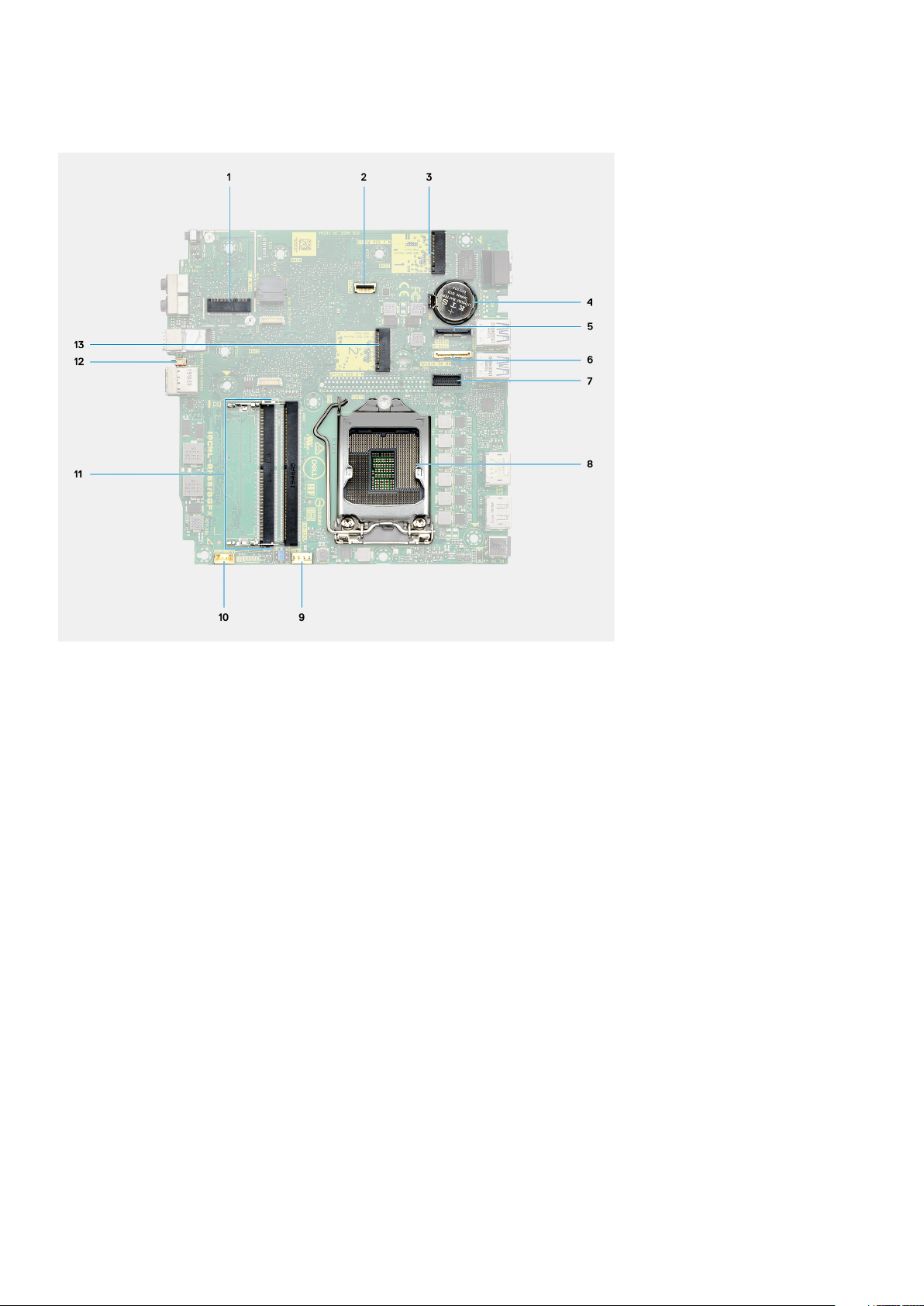
System board Layout
1.
M.2 WLAN connector
2. SATA FFC connector
3. M.2 SSD PCIe connector
4. Coin-cell battery
5. Optional video connector (VGA Port/DisplayPort 1.4 Port/HDMI 2.0b Port/USB 3.2Gen 2 Type-C Port with Alt-mode)
6. Optional connector (USB 3.2Gen 2 Type-C Port)
7. Keyboard and mouse serial port connector
8. Processor socket
9. CPU Fan connector
10. Internal speaker connector
11. Memory slots
12. Intrusion switch
13. M.2 SSD connector
Chassis overview
13
Page 14

Dimensions and weight
Table 2. Dimensions and weight
Description Values
Height:
3
Technical specifications
Front
Rear
Width
Depth
Weight (maximum)
182.00 mm (7.16 in.)
182.00 mm (7.16 in.)
36.00 mm (1.42 in.)
178.56 mm (7.03 in.)
1.38 kg (3.04 lb)
NOTE: The weight of your computer depends on the
configuration ordered and the manufacturing variability.
Chipset
Table 3. Chipset
Description Values
Chipset
Processor
DRAM bus width
Intel Q470
10th Generation Intel Core i3/i5/i7/i9
64-bit (for single channel)
Flash EPROM
PCIe bus
Non-volatile memory Yes
BIOS Configuration Serial Peripheral Interface (SPI) 256 Mbit (32 MB) located at SPI_FLASH on chipset
Trusted Platform Module (Discrete TPM Enabled) 24 KB located at TPM 2.0 on chipset
Firmware TPM (Discrete TPM Disabled) By default the Platform Trust Technology feature is visible to the
NIC EEPROM
14 Technical specifications
32 MB
Up to Gen 3.0
OS
LOM configuration contained within SPI flash ROM instead of
LOM e-fuse
Page 15

Processors
NOTE: Global Standard Products (GSP) are a subset of Dell’s relationship products that are managed for availability and
synchronized transitions on a worldwide basis. They ensure the same platform is available for purchase globally. This
allows customers to reduce the number of configurations managed on a worldwide basis, thereby reducing their costs.
They also enable companies to implement global IT standards by locking in specific product configurations worldwide.
Device Guard (DG) and Credential Guard (CG) are the new security features that are only available on Windows 10 Enterprise today.
Device Guard is a combination of enterprise-related hardware and software security features that, when configured together, will lock a
device down so that it can only run trusted applications. If it is not a trusted application, it cannot run.
Credential Guard uses virtualization-based security to isolate secrets (credentials) so that only privileged system software can access
them. Unauthorized access to these secrets can lead to credential theft attacks. Credential Guard prevents these attacks by protecting
NTLM password hashes and Kerberos Ticket Granting Tickets.
NOTE: Processor numbers are not a measure of performance. Processor availability is subject to change and may vary
by region/country.
Table 4. Processors
Processors Wattage Core
count
th
10
35 W 4 8 3.0 GHz to 3.8
Generation
Intel Core
i3-10100T
th
10
35 W 4 8 3.0 GHz to 3.9
Generation
Intel Core
i3-10300T
th
10
35 W 6 12 2.0 GHz to 3.6
Generation
Intel Core
i5-10400T
th
10
35 W 6 12 2.3 GHz to 3.8
Generation
Intel Core
i5-10500T
th
10
35 W 6 12 2.4 GHz to 4.0
Generation
Intel Core
i5-10600T
Thre
Speed Cache Integrated graphics GSP DG/CG
ad
coun
t
6 MB Intel UHD Graphics 630 No Yes
GHz
8 MB Intel UHD Graphics 630 No Yes
GHz
12 MB Intel UHD Graphics 630 No Yes
GHz
12 MB Intel UHD Graphics 630 Yes Yes
GHz
12 MB Intel UHD Graphics 630 Yes Yes
GHz
Ready
th
10
Generation
Intel Core
i7-10700T
th
10
Generation
Intel Core
i9-10900T
th
10
Generation
35 W 8 16 2.0 GHz to 4.5
GHz
35 W 10 20 1.9 GHz to 4.6
GHz
65 W 4 8 3.6 GHz to 4.3
GHz
16 MB Intel UHD Graphics 630 Yes Yes
20 MB Intel UHD Graphics 630 Yes Yes
6 MB Intel UHD Graphics 630 No Yes
Technical specifications 15
Page 16

Table 4. Processors(continued)
Processors Wattage Core
Intel Core
i3-10100
th
10
Generation
Intel Core
i3-10300
th
10
Generation
Intel Core
i5-10400
10th
Generation
Intel Core
i5-10500
10th
Generation
Intel Core
i5-10600
65 W 4 8 3.7 GHz to 4.4
65 W 6 12 2.9 GHz to 4.3
65 W 6 12 3.1 GHz to 4.5
65 W 6 12 3.3 GHz to 4.8
count
Thre
Speed Cache Integrated graphics GSP DG/CG
ad
coun
t
8 MB Intel UHD Graphics 630 No Yes
GHz
12 MB Intel UHD Graphics 630 No Yes
GHz
12 MB Intel UHD Graphics 630 Yes Yes
GHz
12 MB Intel UHD Graphics 630 Yes Yes
GHz
Ready
10th
Generation
Intel Core
i7-10700
10th
Generation
Intel Core
i9-10900
65 W 8 16 2.9 GHz to 4.7
GHz
65 W 10 20 2.8 GHz to 5.2
GHz
16 MB Intel UHD Graphics 630 Yes Yes
20 MB Intel UHD Graphics 630 Yes Yes
Operating system
• Windows 10 Home (64-bit)
• Windows 10 Professional (64-bit)
• Windows 10 Pro Education (64-bit)
• Windows 10 IoT Enterprise 2019 LTSC (OEM only)
• NeoKylin 7.0 (China only)
• Ubuntu 18.04 (64-bit)
Commercial Platform Windows 10 N-2 and 5-year operating system supportability
All newly introduced commercial platforms (Latitude, OptiPlex, and Precision) will qualify and ship with the most current factory installed
Semi-Annual Channel Windows 10 version (N) and qualify (but not ship) the previous two versions (N-1, N-2). This device platform will
RTS with Windows 10 version v19H2 at the time of launch, and this version will determine the N-2 versions that are initially qualified for
this platform.
For future versions of Windows 10, Dell continues to test the commercial platform with coming Windows 10 releases during device
production and for five years post-production, including both fall and spring releases from Microsoft.
Please reference the Dell Windows as a Service (WaaS) website for additional information about N-2 and 5-year Windows operating
system supportability. Website can be found at this link:
Platforms Qualified on specific versions of Windows 10
This website also includes a matrix of other platforms that are qualified on specific versions of Windows 10.
16
Technical specifications
Page 17

Memory
NOTE: A multiple-DIMM memory option is recommended to prevent any performance reduction. If the system
configuration includes integrated graphics, consider selecting 2 or more DIMMs.
NOTE: Memory modules should be installed in pairs of matched memory size, speed, and technology. If the memory
modules are not installed in matched pairs, the computer continues to operate, but with a slight reduction in
performance. The entire memory range is available to 64-bit operating systems.
Table 5. Memory specifications
Description Values
Slots
Type
Speed
Maximum memory
Minimum memory
Memory size per slot
Configurations supported
Two SODIMM slots
DDR4
• 2666 MHz for Intel Core Pentium/i3/i5 processors
• 2933 MHz for Intel Core i7/i9 processor
NOTE: The Memory speed supported in Brazil for Intel
Core i7/i9 processors is 2666 MHz
64 GB
4 GB
4 GB, 8 GB, 16 GB, 32 GB
• 4 GB, 1 x 4 GB, DDR4, 2666 MHz for Intel Core i3/i5
processors, 2933 MHz for Intel Core i7/i9 processor
• 8 GB, 2 x 4 GB, DDR4, 2666 MHz for Intel Core i3/i5
processors, 2933 MHz for Intel Core i7/i9 processor
• 8 GB, 1 x 8 GB, DDR4, 2666 MHz for Intel Core i3/i5
processors, 2933 MHz for Intel Core i7/i9 processor
• 16 GB, 2 x 8 GB, DDR4, 2666 MHz for Intel Core i3/i5
processors, 2933 MHz for Intel Core i7/i9 processor
• 16 GB, 1 x 16 GB, DDR4, 2666 MHz for Intel Core i3/i5
processors, 2933 MHz for Intel Core i7/i9 processor
• 32 GB, 2 x 16 GB, DDR4, 2666 MHz for Intel Core i3/i5
processors, 2933 MHz for Intel Core i7/i9 processor
• 32 GB, 1 x 32 GB, DDR4, 2666 MHz for Intel Core i3/i5
processors, 2933 MHz for Intel Core i7/i9 processor
• 64 GB, 2 x 32 GB, DDR4, 2666 MHz for Intel Core i3/i5
processors, 2933 MHz for Intel Core i7/i9 processor
Intel Optane memory (optional)
Intel Optane memory functions only as a storage accelerator. It neither replaces nor adds to the memory (RAM) installed on your
computer.
Intel Optane memory is supported on computers that meet the following requirements:
NOTE:
• 7th Generation or higher Intel Core i3/i5/i7 processor
• Windows 10 64-bit version or higher (Anniversary Update)
• Latest version of Intel Rapid Storage Technology driver
• UEFI boot mode configuration
Technical specifications 17
Page 18

Table 6. Intel Optane memory
Description Values
Type
Interface
Connector
Configurations supported
Capacity
Memory/Storage/Storage accelerator
Gen 3 PCIe x4 NVMe
M.2 2280
16 GB and 32 GB
Up to 32 GB
Ports and connectors
Table 7. Ports and connectors
Description Values
External:
Network
USB
One RJ-45 port 10/100/1000 Mbps (rear)
• Without discrete graphics:
• With discrete graphics:
○ For One USB 3.2 Gen 2 Type-A port with PowerShare
(front)
○ One USB 3.2 Gen 2 Type-C port (front)
○ One USB 3.2 Gen 1 Type-A port (rear)
○ Two USB 3.2 Gen 2 Type-A ports (rear)
○ One USB 3.2 Gen 1 Type-A port with Smart Power on
(rear)
○ One USB 3.2 Gen 2 Type-A port with PowerShare (front)
○ One USB 3.2 Gen 2 Type-C port (front)
○ Two USB 3.2 Gen 2 Type-A ports (rear)
○ One USB 3.2 Gen 1 Type-A port with Smart Power on
(rear)
Audio
Video
Memory card reader
Power port
Security
Internal:
18 Technical specifications
• One Universal Audio Jack (front)
• One Line-out port (retaskable Line-in) (front)
• Two DisplayPort 1.4 port (rear)
• One VGA Port/DisplayPort 1.4 Port/HDMI 2.0b Port/ USB 3.2
Gen 2 Type-C Port with Alt-mode (optional) (Not supported
with Discrete graphics)
• One Serial RS232 (optional) (Not supported with Discrete
graphics)
• One Serial/PS2 port (optional) (Not supported with Discrete
graphics)
Not supported
• 4.5 mm DC barrel-type
• 7.4 mm DC barrel-type for 65 W CPU and discrete graphics
One kensington security-cable slot
Page 19

Table 7. Ports and connectors(continued)
Description Values
M.2
• One M.2 2230 slot for WiFi/Bluetooth card
• One M.2 2230/2280 slot for PCIe solid-state drive/Intel
• One M.2 2280 slot for PCIe solid-state drive/Intel Optane
• One SATA slots for 2.5-inch hard-disk drive (for 35 W and 65
• One half-height Gen3 PCIe x8 slot (discrete graphics)
Communications
Ethernet
Table 8. Ethernet specifications
Description Values
Model number
Transfer rate
Intel i219-LM
10/100/1000 Mbps
Optane
W only)
NOTE: To learn more about the features of different
types of M.2 cards, see the knowledge base article
SLN301626.
Wireless module
Table 9. Wireless module specifications
Description Values
Model number
Transfer rate
Frequency bands supported
Wireless standards
Encryption
Bluetooth
Qualcomm QCA9377 Qualcomm QCA61x4A Intel Wi-Fi 6 AX201
Up to 867 Mbps Up to 867 Mbps Up to 2.4 Gbps
2.4 GHz/5 GHz 2.4 GHz/5 GHz 2.4 GHz/5 GHz
• Wi-Fi 802.11 a/b/g
• Wi-Fi 4 (WiFi 802.11n)
• Wi-Fi 5 (WiFi 802.11ac)
• 64-bit and 128-bit WEP
• 128-bit AES-CCMP
• TKIP
5.0 5.0 5.1
802.11ac • 802.11ax (Wi-Fi 6)
• 64-bit and 128-bit WEP
• 128-bit AES-CCMP
• TKIP
• 64-bit and 128-bit WEP
• 128-bit AES-CCMP
• TKIP
Technical specifications 19
Page 20

Graphics and Video controller
Table 10. Integrated graphics specifications
Integrated graphics
Controller External display support Memory size Processor
Intel UHD Graphics 630 • Two DisplayPort 1.4 HBR2
• One VGA/DP 1.4 HBR2/HDMI2.0/USB
Type-C Alt-mode (optional)
Shared system memory 10th Generation Intel
Core i3/i5/i7/i9
Table 11. Discrete graphics specifications
Discrete graphics
Controller External display support Memory size Memory type
AMD Radeon RX 640 • Two mini DisplayPort
• One DisplayPort 1.4
4 GB GDDR5
Audio and Speaker
Table 12. Audio specifications
Description Values
Type
Controller
Stereo conversion
Internal interface
4 Channel High Definition Audio
Realtek ALC3246
24-bit DAC (Digital-to-Analog) and ADC (Analog-to-Digital)
High definition audio interface
External interface
Speakers
Internal speaker amplifier
External volume controls
Speaker output average
Speaker output peak
Subwoofer output
Microphone
• Universal Audio Jack
• Line-out
One
Integrated in ALC3246(Class-D 2 W)
Keyboard shortcut controls
2 W
2.5 W
Not supported
Not supported
Storage
Your computer supports one of the following configurations:
• One 2.5-inch hard-disk drive
• One M.2 2230 or 2280 solid-state drive (class 35 or class 40)
• One 2.5-inch hard-disk drive and one M.2 16 or 32 GB Intel Optane memory
20
Technical specifications
Page 21

The primary drive of your computer varies with the storage configuration. For computers:
• with a M.2 solid-state drive, the M.2 solid-state drive is the primary drive
• without a M.2 drive, the 2.5-inch hard-disk drive is the primary drive
Table 13. Storage specifications
Storage type Interface type Capacity
2.5-inch, 5400 RPM, hard-disk drive SATA 3.0 Up to 2 TB
2.5-inch, 7200 RPM, hard-disk drive SATA 3.0 Up to 1 TB
2.5-inch, 7200 RPM, FIPS Self Encrypting Opal 2.0, harddisk drive
2.5-inch. solid-state drive SATA Class 20 512 GB
M.2 2230 solid-state drive Gen 3 PCIe x4 NVMe, Class 35 Up to 512 GB
M.2 2280 solid-state drive Gen 3 PCIe x4 NVMe, Class 40 Up to 2 TB
M.2 2280 Opal Self-Encrypting solid-state drive Gen 3 PCIe x4 NVMe, Class 40 Up to 1 TB
SATA 3.0 500 GB
Power adapter
Table 14. Power adapter specifications
Description Values
Type
Diameter (connector)
Input voltage
Input frequency
90 W (for 35 W CPU) 130 W (for 35 W CPU) 180 W (for 65 W CPU and
discrete graphics)
4.5 mm x 2.9 mm 4.5 mm x 2.9 mm 7.4 mm x 5.1 mm
100 VAC x 240 VAC 100 VAC x 240 VAC 100 VAC x 240 VAC
50 Hz x 60 Hz 50 Hz x 60 Hz 50 Hz x 60 Hz
Input current (maximum)
Output current (continuous)
Rated output voltage
Temperature range:
Operating
Storage
Add-in cards
Table 15. Add-in cards
Add-in cards
USB Type-C 3.1 PCIe Card
2nd-gigabit NIC add-in card
1.5 A 2.5 A 2.34 A
4.62 A 6.7 A 9.23 A
19.50 VDC 19.50 VDC 19.50 VDC
0°C to 40°C (32°F to 104°F) 0°C to 40°C (32°F to 104°F) 0°C to 40°C (32°F to 104°F)
-40°C to 70°C (-40°F to
158°F)
-40°C to 70°C (-40°F to
158°F)
-40°C to 70°C (-40°F to
158°F)
Technical specifications 21
Page 22

Table 15. Add-in cards(continued)
Add-in cards
PCIe x1 5/2.5 GbE NIC
PCIe Serial Card (LP only)
PCIe Parallel Card (LP only)
Data security
Table 16. Data security
Data security options Values
McAfee Small Business Security 30 Day Free Trial Supported
McAfee Small Business Security 12-month subscription Supported
McAfee Small Business Security 36-month subscription Supported
SafeGuard and Response, powered by VMware Carbon Black and
Secureworks
Next Generation anti-virus (NGAV) Supported
Endpoint Detection and Response (EDR) Supported
Threat Detection and Response (TDR) Supported
Managed Endpoint Detection and Response Supported
Incident Management Retainer Supported
Emergency Incident Response Supported
SafeData Supported
Supported
Environmental
Table 17. Environmental specifications
Feature OptiPlex 7080 Micro
Recyclable packaging Yes
BFR/PVC—free chassis No
MultiPack packaging Yes (US only) (optional)
Energy-Efficient Power Supply Standard
ENV0424 compliant Yes
NOTE: Wood‐based fiber packaging contains a minimum of 35% recycled content by total weight of wood‐based fiber.
Packaging that contains without wood‐based fiber can be claimed as Not Applicable.
Energy Star and Trusted Platform Module (TPM)
Table 18. Energy Star and TPM
Features Specifications
Energy Star 8.0 Compliant configurations available
22 Technical specifications
Page 23

Table 18. Energy Star and TPM(continued)
Features Specifications
Trusted Platform Module (TPM) 2.0
Firmware-TPM (Discrete TPM disabled) Optional
NOTE:
1
TPM 2.0 is FIPS 140-2 certified.
2
TPM is not available in all countries.
1,2
Integrated on system board
Computer environment
Airborne contaminant level: G1 as defined by ISA-S71.04-1985
Table 19. Computer environment
Description Operating Storage
Temperature range
Relative humidity (maximum)
Vibration (maximum)
Shock (maximum)
Altitude (maximum)
* Measured using a random vibration spectrum that simulates user environment.
† Measured using a 2 ms half-sine pulse when the hard drive is in use.
*
10°C–35°C (50°F–95°F) -40°C-65°C (-40°F-149°F)
20% to 80% (non-condensing) 5% to 95% (non-condensing)
0.26 GRMS random at 5 Hz to 350 Hz 1.37 GRMS random at 5 Hz to 350 Hz
Bottom half-sine pulse with a change in
velocity of 50.8 cm/sec (20 in./sec)
3048 m (10,000 ft) 10,668 m (35,000 ft)
Service and support
NOTE:
For more details on Dell Service Plans, see https://www.dell.com/learn/us/en/19/services/warranty-support-
services.
Table 20. Warranty
Warranty
3 Years Basic Warranty with Hardware Service on site service after remote diagnosis
105G half-sine pulse with a change in
velocity of 133 cm/sec (52.5 in./sec)
4 Years Basic Warranty Extension
5 Years Basic Warranty Extension
3 Years ProSupport and Next Business Day on-site service
4 Years ProSupport and Next Business Day on-site service
5 Years ProSupport and Next Business Day on-site service
3 Years ProSupport Plus for Client with Next Business Day on-site service
4 Years ProSupport Plus for Client with Next Business Day on-site service
5 Years ProSupport Plus for Client with Next Business Day on-site service
Technical specifications 23
Page 24

Table 21. Accidental damage services
Accidental Damage Services
3 Years Accidental Damage Service
4 Years Accidental Damage Service
5 Years Accidental Damage Service
24 Technical specifications
Page 25

This chapter details the supported operating systems along with instructions on how to install the drivers.
Topics:
• Downloading Windows drivers
Downloading Windows drivers
Steps
1. Turn on the .
2. Go to Dell.com/support.
3. Click Product Support, enter the Service Tag of your , and then click Submit.
NOTE: If you do not have the Service Tag, use the auto detect feature or manually browse for your model.
4. Click Drivers and Downloads.
5. Select the operating system installed on your .
6. Scroll down the page and select the driver to install.
7. Click Download File to download the driver for your .
8. After the download is complete, navigate to the folder where you saved the driver file.
9. Double-click the driver file icon and follow the instructions on the screen.
4
Software
Software 25
Page 26

5
System setup
CAUTION: Unless you are an expert computer user, do not change the settings in the BIOS Setup program. Certain
changes can make your computer work incorrectly.
NOTE: Before you change BIOS Setup program, it is recommended that you write down the BIOS Setup program screen
information for future reference.
Use the BIOS Setup program for the following purposes:
• Get information about the hardware installed in your computer, such as the amount of RAM and the size of the hard drive.
• Change the system configuration information.
• Set or change a user-selectable option, such as the user password, type of hard drive installed, and enabling or disabling base devices.
Topics:
• Boot menu
• Navigation keys
• Boot Sequence
• System setup options
• Updating the BIOS in Windows
• System and setup password
Boot menu
Press <F12> when the Dell logo appears to initiate a one-time boot menu with a list of the valid boot devices for the system. Diagnostics
and BIOS Setup options are also included in this menu. The devices listed on the boot menu depend on the bootable devices in the system.
This menu is useful when you are attempting to boot to a particular device or to bring up the diagnostics for the system. Using the boot
menu does not make any changes to the boot order stored in the BIOS.
The options are:
• UEFI Boot:
○ Windows Boot Manager
• Other Options:
○ BIOS Setup
○ BIOS Flash Update
○ Diagnostics
○ Change Boot Mode Settings
Navigation keys
For most of the System Setup options, changes that you make are recorded but do not take effect until you
NOTE:
restart the system.
Keys Navigation
Up arrow Moves to the previous field.
Down arrow Moves to the next field.
Enter Selects a value in the selected field (if applicable) or follow the link in the field.
Spacebar Expands or collapses a drop-down list, if applicable.
Tab Moves to the next focus area.
26 System setup
Page 27

Keys Navigation
Esc Moves to the previous page until you view the main screen. Pressing Esc in the main screen displays a message
that prompts you to save any unsaved changes and restarts the system.
Boot Sequence
Boot sequence enables you to bypass the System Setup–defined boot device order and boot directly to a specific device (for example:
optical drive or hard drive). During the Power-on Self-Test (POST), when the Dell logo appears, you can:
• Access System Setup by pressing F2 key
• Bring up the one-time boot menu by pressing F12 key.
The one-time boot menu displays the devices that you can boot from including the diagnostic option. The boot menu options are:
• Removable Drive (if available)
• STXXXX Drive
NOTE: XXXX denotes the SATA drive number.
• Optical Drive (if available)
• SATA Hard Drive (if available)
• Diagnostics
NOTE: Choosing Diagnostics, displays the ePSA diagnostics screen.
The boot sequence screen also displays the option to access the System Setup screen.
System setup options
NOTE: Depending on the computer and its installed devices, the items listed in this section may or may not appear.
General options
Table 22. General
Option Description
System Information Displays the following information:
• System Information: Displays BIOS Version, Service Tag, Asset Tag, Ownership Tag,
Manufacture Date, Ownership Date, and the Express Service Code.
• Memory Information: Displays Memory Installed, Memory Available, Memory Speed,
Memory Channel Mode, Memory Technology, DIMM 1 Size, and DIMM 2 Size.
• PCI Information: Displays Slot1_M.2, Slot2_M.2, Slot3_M.2
• Processor Information: Displays Processor Type, Core Count, Processor ID, Current Clock
Speed, Minimum Clock Speed, Maximum Clock Speed, Processor L2 Cache, Processor
L3 Cache, HT Capable, and 64-Bit Technology.
• Device Information: Displays SATA-0, M.2 PCIe SSD-2, LOM MAC Address, Video
Controller, Audio Controller, Wi-Fi Device, and Bluetooth Device.
Boot Sequence Allows you to specify the order in which the computer attempts to find an operating system from
the devices specified in this list.
UEFI Boot Path Security This option controls whether or not the system prompts the user to enter the Admin password
when booting a UEFI boot path from the F12 Boot Menu.
Date/Time Allows you to set the date and time settings. Changes to the system date and time take effect
immediately.
.
System setup
27
Page 28

System information
Table 23. System Configuration
Option Description
Integrated NIC Allows you to control the onboard LAN controller. The option ‘Enable UEFI Network Stack’ is not
selected by default. The options are:
• Disabled
• Enabled
• Enabled w/PXE (default)
NOTE: Depending on the computer and its installed devices, the items that are listed
in this section may or may not appear.
SATA Operation Allows you to configure the operating mode of the integrated hard drive controller.
• Disabled = The SATA controllers are hidden
• AHCI = SATA is configured for AHCI mode
• RAID ON = SATA is configured to support RAID mode (selected by default)
Drives Allows you to enable or disable the various drives onboard:
• SATA-0 (enabled by default)
• M.2 PCIe SSD-0 (enabled by default)
Smart Reporting This field controls whether hard-drive errors for integrated drives are reported during system
startup. The Enable Smart Reporting option is disabled by default.
USB Configuration Allows you to enable or disable the integrated USB controller for:
• Enable USB Boot Support
• Enable Front USB Ports
• Enable Rear USB Ports
All the options are enabled by default.
Front USB Configuration Allows you to enable or disable the front USB ports. All the ports are enabled by default.
Rear USB Configuration Allows you to enable or disable the back USB ports. All the ports are enabled by default.
USB PowerShare This option allows you to charge the external devices, such as mobile phones, music player. This
option is disabled by default.
Audio Allows you to enable or disable the integrated audio controller. The option Enable Audio is selected
by default.
• Enable Microphone
• Enable Internal Speaker
Both the options are selected by default.
Dust Filter Maintenance Allows you to enable or disable BIOS messages for maintaining the optional dust filter that is installed
in your computer. BIOS will generate a pre-boot reminder to clean or replace the dust filter based on
the interval set. The option Disabled is selected by default.
• Disabled
• 15 days
• 30 days
• 60 days
• 90 days
• 120 days
• 150 days
• 180 days
28 System setup
Page 29

Video screen options
Table 24. Video
Option Description
Primary Display Allows you to select the primary display when multiple controllers are available in the system.
• Auto (default)
• Intel HD Graphics
NOTE: If you do not select Auto, the on-board graphics device will be present and
enabled.
Security
Table 25. Security
Option Description
Admin Password Allows you to set, change, and delete the admin password.
System Password Allows you to set, change, and delete the system password.
Internal HDD-0 Password Allows you to set, change, and delete the computer’s internal hard drive password.
Password Configuration Allows you to control the minimum and maximum number of characters that are allowed for an
administrative password and the system password. The range of characters is between 4 and 32.
Password Bypass This option lets you bypass the System (Boot) Password and the internal hard drive password
prompts during a system restart.
• Disabled — Always prompt for the system and internal HDD password when they are set. This
option is disabled by default.
• Reboot Bypass — Bypass the password prompts on Restarts (warm boots).
NOTE: The system will always prompt for the system and internal HDD passwords
when powered on from the off state (a cold boot). Also, the system will always prompt
for passwords on any module bay HDDs that may be present.
Password Change This option lets you determine whether changes to the System and Hard Disk passwords are
permitted when an administrator password is set.
Allow Non-Admin Password Changes - This option is enabled by default.
UEFI Capsule Firmware Updates This option controls whether this system allows BIOS updates via UEFI capsule update packages.
This option is selected by default. Disabling this option will block BIOS updates from services such as
Microsoft Windows Update and Linux Vendor Firmware Service (LVFS).
TPM 2.0 Security Allows you to control whether the Trusted Platform Module (TPM) is visible to the operating
system.
• TPM On (default)
• Clear
• PPI Bypass for Enable Commands
• PPI Bypass for Disable Commands
• PPI Bypass for Clear Commands
• Attestation Enable (default)
• Key Storage Enable (default)
• SHA-256 (default)
Choose any one option:
• Disabled
• Enabled (default)
System setup 29
Page 30

Table 25. Security(continued)
Option Description
Absolute This field lets you Enable, Disable or permanently Disable the BIOS module interface of the optional
Absolute Persistence Module service from Absolute Software.
• Enabled - This option is selected by default.
• Disable
• Permanently Disabled
Chassis Intrusion This field controls the chassis intrusion feature.
Choose any one of the options:
• Disabled (default)
• Enabled
• On-Silent
OROM Keyboard Access This option determines whether users can enter Option ROM Configuration screens using hotkeys
during boot.
• Enabled - This option is selected by default.
• Disable
• One Time Enable
Admin Setup Lockout Allows you to prevent users from entering Setup when Admin password is set. This option is not set
by default.
Master Password Lockout Allows you to disable master password support. Hard Disk passwords need to be cleared before the
settings can be changed. This option is not set by default.
HDD Protection Support This field allows users to enable and disable the HDD Protection feature. This option is not set by
default.
SMM Security Mitigation Allows you to enable or disable additional UEFI SMM Security Mitigation protections. This option is
not set by default.
Secure boot options
Table 26. Secure Boot
Option Description
Secure Boot Enable Allows you to enable or disable Secure Boot feature
• Secure Boot Enable.
This option is not selected by default.
Secure Boot Mode Allows you to modify the behavior of Secure Boot to allow evaluation or enforcement of UEFI
driver signatures.
• Deployed Mode (default).
• Audit Mode.
Expert key Management Allows you to manipulate the security key databases only if the system is in Custom Mode. The
Enable Custom Mode option is disabled by default. The options are:
• PK (default).
• KEK.
• db.
• dbx.
If you enable the Custom Mode, the relevant options for PK, KEK, db, and dbx appear. The
options are:
• Save to File- Saves the key to a user-selected file.
30 System setup
Page 31

Table 26. Secure Boot(continued)
Option Description
• Replace from File- Replaces the current key with a key from a user-selected file.
• Append from File- Adds a key to the current database from a user-selected file.
• Delete- Deletes the selected key.
• Reset All Keys- Resets to default setting.
• Delete All Keys- Deletes all the keys.
NOTE: If you disable the Custom Mode, all the changes made will be erased and the
keys will restore to default settings.
Intel Software Guard Extensions options
Table 27. Intel Software Guard Extensions
Option Description
Intel SGX Enable
Enclave Memory Size
This field specifies you to provide a secured environment for
running code/storing sensitive information in the context of the
main OS.
Click one of the following options:
• Disabled
• Enabled
• Software controlled—Default
This option sets SGX Enclave Reserve Memory Size
Click one of the following options:
• 32 MB
• 64 MB
• 128 MB—Default
Performance
Table 28. Performance
Option Description
Multi Core Support
This field specifies whether the processor has one or all cores
enabled. The performance of some applications improves with the
additional cores.
• All—Default
• 1
• 2
• 3
Intel SpeedStep
C-States Control
Allows you to enable or disable the Intel SpeedStep mode of
processor.
• Enable Intel SpeedStep
This option is set by default.
Allows you to enable or disable the additional processor sleep
states.
• C states
System setup 31
Page 32

Table 28. Performance(continued)
Option Description
This option is set by default.
Intel TurboBoost
Hyper-Thread Control
Allows you to enable or disable the Intel TurboBoost mode of the
processor.
• Enable Intel TurboBoost
This option is set by default.
Allows you to enable or disable the HyperThreading in the
processor.
• Disabled
• Enabled—Default
Power management
Table 29. Power Management
Option Description
AC Recovery Determines how the system responds when AC power is re-applied after a power loss. You can set
the AC Recovery to:
• Power Off
• Power On
• Last Power State
This option is Power Off by default.
Enable Intel Speed Shift
Technology
Auto On Time Sets time to automatically turn on the computer. Time is kept in standard 12-hour format
Deep Sleep Control Allows you to define the controls when Deep Sleep is enabled.
USB Wake Support Allows you to enable the USB devices to wake the computer from standby mode. The option
Wake on LAN/WWAN This option allows the computer to power up from the off state when triggered by a special LAN
Allows you to enable or disable Intel Speed Shift Technology support. The option Enable Intel
Speed Shift Technology is set by default.
(hour:minutes:seconds). Change the startup time by typing the values in the time and AM/PM
fields.
NOTE: This feature does not work if you turn off your computer using the switch on a
power strip or surge protector or if Auto Power is set to disabled.
• Disabled
• Enabled in S5 only
• Enabled in S4 and S5
This option is Enabled in S4 and S5 by default
Enable USB Wake Support is selected by default.
signal. This feature only works when the computer is connected to AC power supply.
• Disabled - Does not allows the system to power on by special LAN signals when it receives a
wake-up signal from the LAN or wireless LAN.
• LAN or WLAN - Allows the system to be powered on by special LAN or wireless LAN signals.
• LAN Only - Allows the system to be powered on by special LAN signals.
• LAN with PXE Boot - A wakeup packet sent to the system in either the S4 or S5 state, that
will cause the system to wake-up and immediately boot to PXE.
• WLAN Only - Allows the system to be powered on by special WLAN signals.
This option is Disabled by default.
32 System setup
Page 33

Table 29. Power Management (continued)
Option Description
Block Sleep Allows you to block entering to sleep (S3 state) in OS environment. This option is disabled by
default.
Post behavior
Table 30. POST Behavior
Option Description
Adapter Warnings This option lets you choose whether the system displays warning messages when you use certain
power adapters. This option is enabled by default.
Numlock LED Allows you to enable or disable the Numlock feature when your computer starts. This option is
enabled by default.
Keyboard Errors Allows you to enable or disable the keyboard error reporting when the computer starts. The option
Enable Keyboard Error Detection is enabled by default.
Fast Boot This option can speed up the boot process by bypassing some compatibility steps:
• Minimal — The system boots quickly, unless the BIOS has been updated, memory changed, or
the previous POST did not complete.
• Thorough — The system does not skip any steps in the boot process.
• Auto — This allows the operating system to control this setting (this works only when the
operating system supports Simple Boot Flag).
This option is set to Thorough by default.
Extend BIOS POST Time This option creates an additional pre-boot delay.
• 0 seconds (default)
• 5 seconds
• 10 seconds
Full Screen Logo This option will display full screen logo if your image match screen resolution. The option Enable Full
Screen Logo is not set by default.
Warnings and Errors This option causes the boot process to only pause when warning or errors are detected. Choose any
one of the option:
• Prompt on Warnings and Errors - default
• Continue on Warnings
• Continue on Warnings and Errors
Manageability
Option
Intel AMT
Capability
USB Provision When enabled Intel AMT can be provisioned using the local provisioning file using a USB storage device.
Description
Allows you to provision AMT and MEB Hotkey function is enabled, during the system boot.
• Disabled
• Enabled
• Restrict MEBx Access - by default
• Enable USB Provision - disabled by default
MEBx Hotkey Allows you to specify whether the MEBx Hotkey function should enable, during the system boot.
• Enable MEBx hotkey—disabled by default
System setup 33
Page 34

Virtualization support
Table 31. Virtualization Support
Option Description
Virtualization
VT for Direct I/O
This option specifies whether a Virtual Machine Monitor (VMM) can utilize the additional hardware
capabilities provided by the Intel Virtualization technology.
• Enable Intel Virtualization Technology
This option is set by default.
Enables or disables the Virtual Machine Monitor (VMM) from utilizing the additional hardware
capabilities provided by the Intel Virtualization technology for direct I/O.
• Enable VT for Direct I/O
This option is set by default.
Wireless options
Table 32. Wireless
Option Description
Wireless Device Enable
Allows you to enable or disable the internal wireless devices.
The options are:
• WLAN/WiGig
• Bluetooth
All the options are enabled by default.
Maintenance
Table 33. Maintenance
Option Description
Service Tag
Asset Tag
SERR Messages Controls the SERR message mechanism. This option is set by default. Some graphics cards require that
BIOS Downgrade
Data Wipe
BIOS Recovery
Displays the service tag of your computer.
Allows you to create a system asset tag if an asset tag is not already set.
This option is not set by default.
the SERR message mechanism be disabled.
Allows you to flash previous revisions of the system firmware.
• Allow BIOS Downgrade
This option is set by default.
Allows you to securely erase data from all internal storage devices.
• Wipe on Next Boot
This option is not set by default.
BIOS Recovery from Hard Drive—This option is set by default. Allows you to recover the corrupted
BIOS from a recovery file on the HDD or an external USB key.
34 System setup
NOTE: BIOS Recovery from Hard Drive field must be enabled.
Page 35

Table 33. Maintenance (continued)
Option Description
Always Perform Integrity Check—Performs integrity check on every boot.
First Power On Date Allows you the set Ownership date. The option Set Ownership Date is not set by default.
System logs
Table 34. System Logs
Option Description
BIOS events
Allows you to view and clear the System Setup (BIOS) POST events.
Advanced configuration
Table 35. Advanced configuration
Option Description
ASPM Allows you to set the ASPM level.
• Auto (default) - There is handshaking between the device and PCI Express hub to determine the
best ASPM mode supported by the device.
• Disabled - ASPM power management is turned off at all time.
• L1 Only - ASPM power management is set to use L1.
SupportAssist System Resolution
Option
Auto OS Recovery
Threshold
Description
Allows you to control the automatic boot flow for SupportAssist System. Options are:
• Off
• 1
• 2 (Enabled by default)
• 3
SupportAssist OS
Recovery
BIOSConnect BIOSConnect enable or disable cloud Service OS upon absence of Local OS Recovery (Enabled by default).
Allows you to recover the SupportAssist OS Recovery (Enabled by default).
Updating the BIOS in Windows
Prerequisites
It is recommended to update your BIOS (System Setup) when you replace the system board or if an update is available.
About this task
If BitLocker is enabled, it must be suspended prior to updating the system BIOS, and then re enabled after the
NOTE:
BIOS update is completed.
Steps
1. Restart the computer.
2. Go to Dell.com/support.
System setup
35
Page 36

• Enter the Service Tag or Express Service Code and click Submit.
• Click Detect Product and follow the instructions on screen.
3. If you are unable to detect or find the Service Tag, click Choose from all products.
4. Choose the Products category from the list.
NOTE: Choose the appropriate category to reach the product page.
5. Select your computer model and the Product Support page of your computer appears.
6. Click Get drivers and click Drivers and Downloads.
The Drivers and Downloads section opens.
7. Click Find it myself.
8. Click BIOS to view the BIOS versions.
9. Identify the latest BIOS file and click Download.
10. Select your preferred download method in the Please select your download method below window, click Download File.
The File Download window appears.
11. Click Save to save the file on your computer.
12. Click Run to install the updated BIOS settings on your computer.
Follow the instructions on the screen.
Updating BIOS on systems with BitLocker enabled
CAUTION: If BitLocker is not suspended before updating the BIOS, the next time you reboot the system it will not
recognize the BitLocker key. You will then be prompted to enter the recovery key to progress and the system will ask for
this on each reboot. If the recovery key is not known this can result in data loss or an unnecessary operating system re-
install. For more information on this subject, see Knowledge Article: https://www.dell.com/support/article/sln153694
Updating your system BIOS using a USB flash drive
About this task
If the system cannot load into Windows but there is still a need to update the BIOS, download the BIOS file using another system and save
it to a bootable USB Flash Drive.
NOTE:
You will need to use a bootable USB Flash drive. Please refer to the following article for further details: https://
www.dell.com/support/article/sln143196/
Steps
1. Download the BIOS update .EXE file to another system.
2. Copy the file e.g. O9010A12.EXE onto the bootable USB Flash drive.
3. Insert the USB Flash drive into the system that requires the BIOS update.
4. Restart the system and press F12 when the Dell Splash logo appears to display the One Time Boot Menu.
5. Using arrow keys, select USB Storage Device and click Return.
6. The system will boot to a Diag C:\> prompt.
7. Run the file by typing the full filename e.g. O9010A12.exe and press Return.
8. The BIOS Update Utility will load, follow the instructions on screen.
36
System setup
Page 37
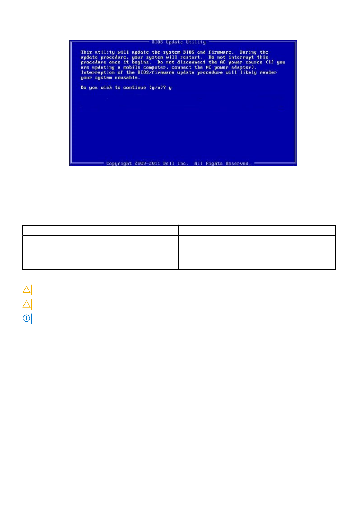
Figure 1. DOS BIOS Update Screen
System and setup password
Table 36. System and setup password
Password type Description
System password Password that you must enter to log on to your system.
Setup password Password that you must enter to access and make changes to the
BIOS settings of your computer.
You can create a system password and a setup password to secure your computer.
CAUTION: The password features provide a basic level of security for the data on your computer.
CAUTION: Anyone can access the data stored on your computer if it is not locked and left unattended.
NOTE: System and setup password feature is disabled.
Assigning a system setup password
Prerequisites
You can assign a new System or Admin Password only when the status is in Not Set.
About this task
To enter the system setup, press F2 immediately after a power-on or reboot.
Steps
1. In the System BIOS or System Setup screen, select Security and press Enter.
The Security screen is displayed.
2. Select System/Admin Password and create a password in the Enter the new password field.
Use the following guidelines to assign the system password:
• A password can have up to 32 characters.
System setup
37
Page 38

• The password can contain the numbers 0 through 9.
• Only lower case letters are valid, upper case letters are not allowed.
• Only the following special characters are allowed: space, (”), (+), (,), (-), (.), (/), (;), ([), (\), (]), (`).
3. Type the system password that you entered earlier in the Confirm new password field and click OK.
4. Press Esc and a message prompts you to save the changes.
5. Press Y to save the changes.
The computer reboots.
Deleting or changing an existing system setup password
Prerequisites
Ensure that the Password Status is Unlocked (in the System Setup) before attempting to delete or change the existing System and
Setup password. You cannot delete or change an existing System or Setup password, if the Password Status is Locked.
About this task
To enter the System Setup, press F2 immediately after a power-on or reboot.
Steps
1. In the System BIOS or System Setup screen, select System Security and press Enter.
The System Security screen is displayed.
2. In the System Security screen, verify that Password Status is Unlocked.
3. Select System Password, alter or delete the existing system password and press Enter or Tab.
4. Select Setup Password, alter or delete the existing setup password and press Enter or Tab.
NOTE:
If you change the System and/or Setup password, re enter the new password when prompted. If you delete
the System and Setup password, confirm the deletion when prompted.
5. Press Esc and a message prompts you to save the changes.
6. Press Y to save the changes and exit from System Setup.
The computer restarts.
38
System setup
Page 39

6
Getting help
Topics:
• Contacting Dell
Contacting Dell
Prerequisites
NOTE: If you do not have an active Internet connection, you can find contact information on your purchase invoice,
packing slip, bill, or Dell product catalog.
About this task
Dell provides several online and telephone-based support and service options. Availability varies by country and product, and some services
may not be available in your area. To contact Dell for sales, technical support, or customer service issues:
Steps
1. Go to Dell.com/support.
2. Select your support category.
3. Verify your country or region in the Choose a Country/Region drop-down list at the bottom of the page.
4. Select the appropriate service or support link based on your need.
Getting help 39
 Loading...