

Dell W-AP124, W-AP125 Owner's Manual
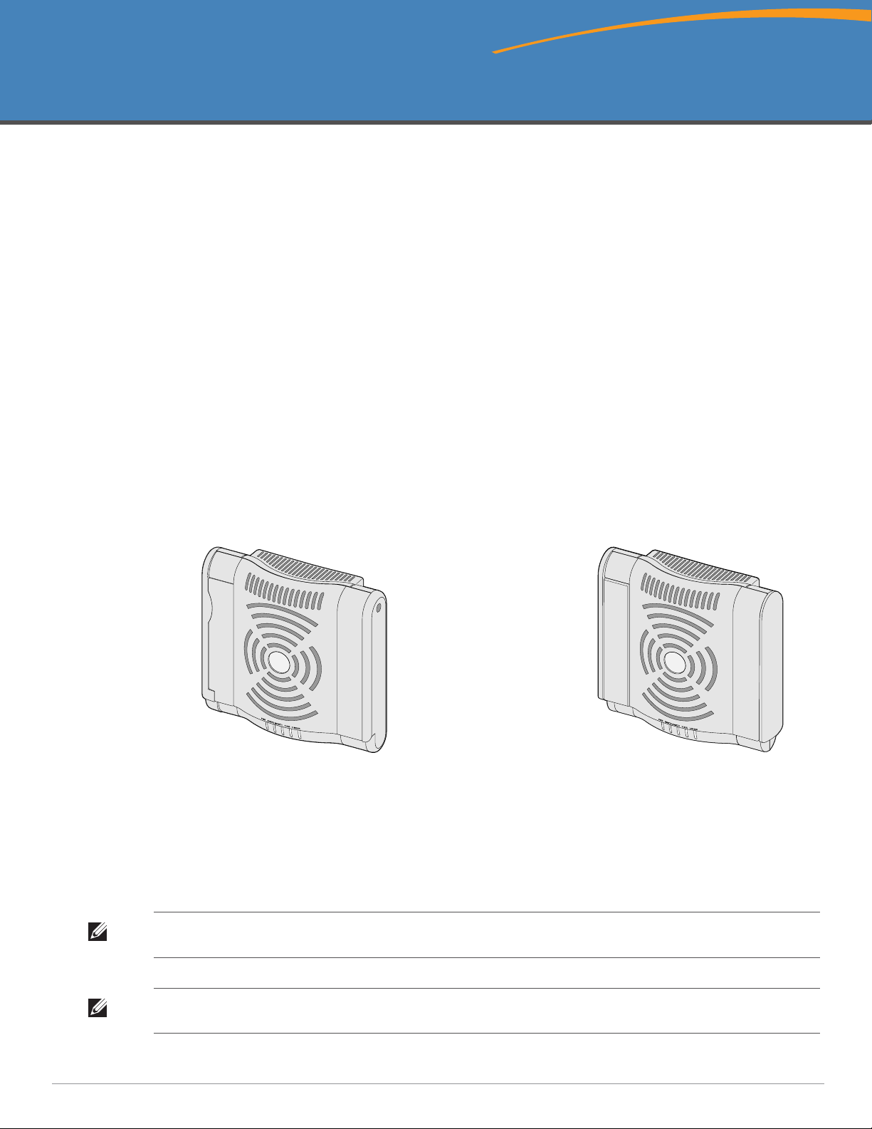
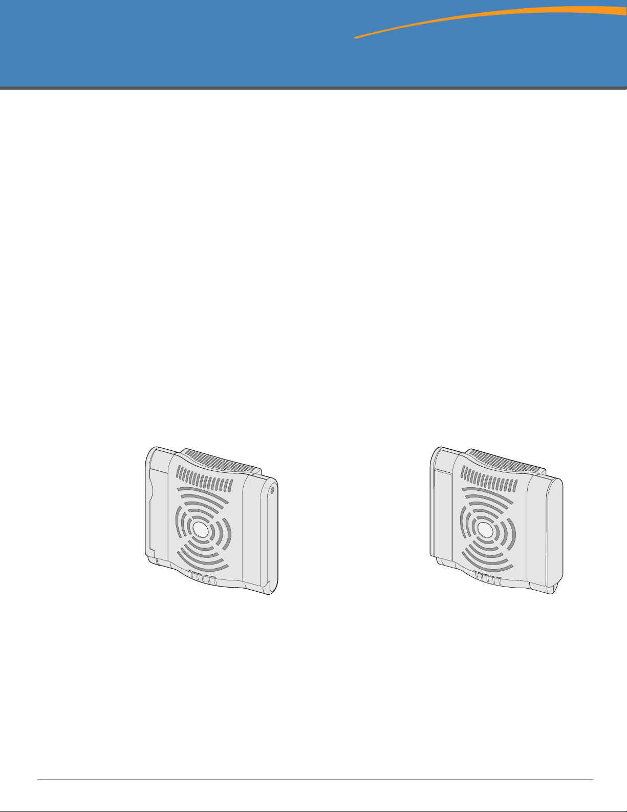
Dell PowerConnect W-AP120 Series AP
ap12_001
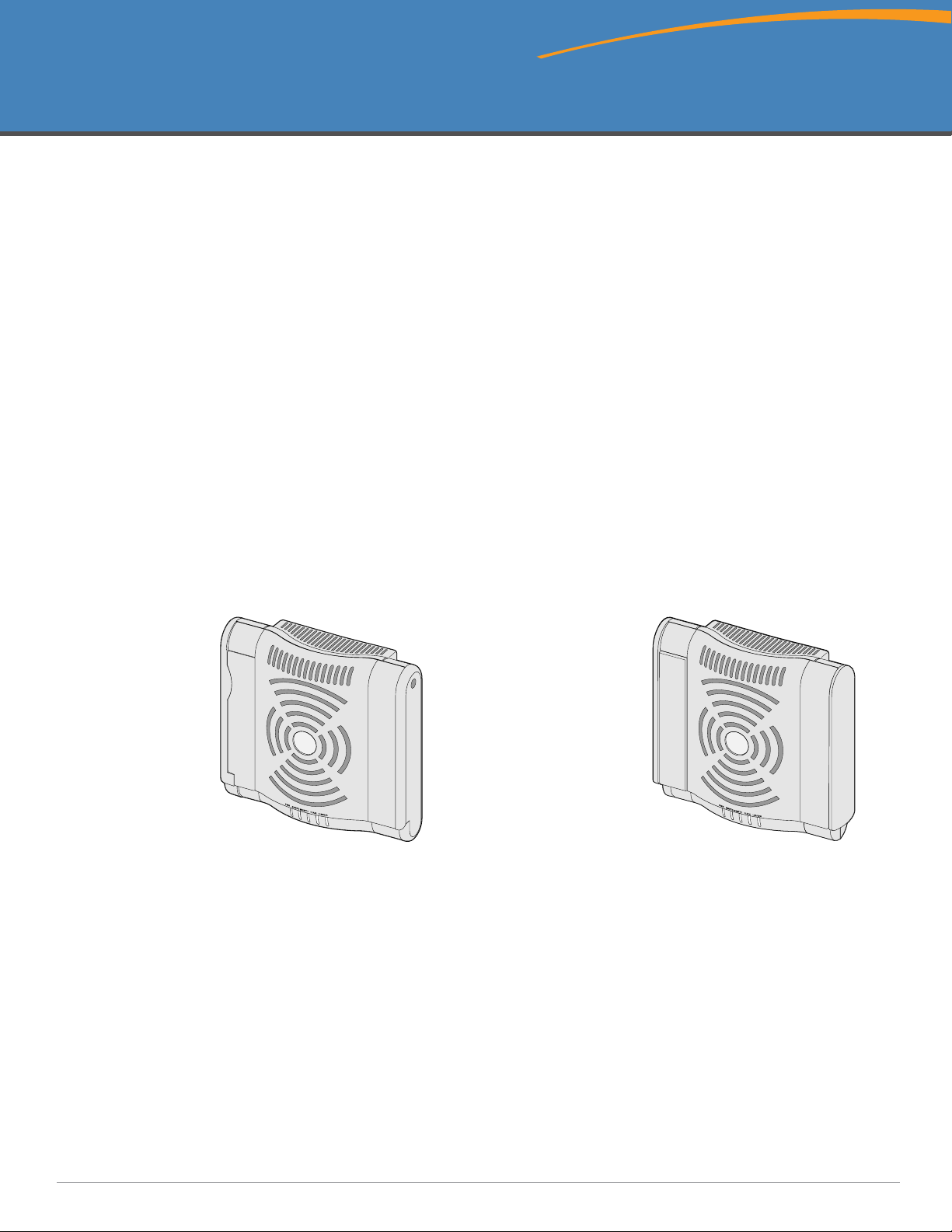
W-AP120/W-AP124
(3 x RP-SMA interfaces for detachable antennas)
W-AP121/W-AP125
(3 x integrated dual-band antennas)
Installation Guide
Installation Guide
The Dell W-AP120 series of wireless access points support the imminent IEEE 802.11n (currently draft 2.0)
standard for high-performance WLAN. These access points use MIMO (Multiple-in, Multiple-out) technology
and other high-throughput mode techniques to deliver high-performance, pre-802.11n 2.4 GHz and 5 GHz
functionality while simultaneously supporting existing 802.11a/b/g wireless services. The W-AP120 series access
points are available in versions with single or dual radios and with integrated antennas or RP-SMA interfaces that
support detachable antennas. The W-AP120 series access points work only in conjunction with an Dell controller.
The Dell W-AP120 series access points provide the following capabilities:
z Wireless transceiver
z Protocol-independent networking functionality
z IEEE 802.11a/b/g or 802.11n operation as a wireless access point
z IEEE 802.11a/b/g or 802.11n operation as a wireless air monitor
z Compatibility with IEEE 802.3af PoE as well as high power over Ethernet pre-standards
(PoE + / 802.3at)
z Central management configuration and upgrades through an Dell controller
z Upgrade of W-AP120 series a/b/g models to 802.11n (draft) compliance through a controller license
Figure 1 W-AP120 Series Access Points
Package Contents
z AP-120 series access point
z Installation guide (this document)
Note: Inform your supplier if there are any incorrect, missing, or damaged parts. If possible, retain the carton, including the original
packing materials. Use these materials to repack and return the unit to the supplier if needed.
Note: Additional mounting kits for use with the W-AP120 series access points are sold separately. Contact your Dell sales
representative for details.
0510745-MU-01 | July 2010 1

Before You Begin
WLAN Planning
Determine how many Dell APs are needed for your wireless network deployment and where they will be installed.
You can easily accomplish this planning using Dell’s automated RF Plan site-survey software (available
separately). This process is considered WLAN or RF planning and should have been completed during the master
Dell controller installation and configuration. In typical Dell installations, the controllers are configured and
installed before the APs.
For WLAN planning assistance, refer to the Indoor Access Points: Site Survey and Planning Pre-Deployment Guide
and the RF Plan Installation and User Guide.
Pre-Installation Network Requirements
After WLAN planning is complete and the appropriate products and their placement have been determined, the
Dell controller(s) must be installed and initial setup performed before the Dell Access Points are deployed.
For initial setup of the controller, refer to the ArubaOS Quick Start Guide for the software version installed on
your controller.
Pre-Installation Checklist
Before installing your W-AP120 series access point, be sure that you have the following:
z For the W-AP120/W-AP124: External antennas as specified in the network deployment plan
z CAT5 UTP cable of required length
z One of the following power sources:
IEEE 802.3af-compliant Power over Ethernet (PoE) source
Supports full functionality for W-AP120/W-AP121; supports reduced functionality for W-AP124/W-
AP125
IEEE Power Over Ethernet + (PoE+) source output at 56 Volts @ 350 mA
The POE source can be any power source equipment (PSE) controller or midspan PSE device
Dell AP AC-DC adapter kit (sold separately)
z Dell controller provisioned on the network:
Layer 2/3 network connectivity to your access point
One of the following network services:
z Aruba Discovery Protocol (ADP)
z DNS server with an “A” record
z DHCP Server with vendor-specific options
Summary of the Setup Process
Note: It is important that you verify the items listed under Pre-Installation Checklist before you attempt to set up and install an W-
AP120 series AP.
Successful setup of an AP-120 series access point consists of five tasks, which must be performed in this order:
1. Verify pre-installation connectivity.
2. Identify the specific installation location for each AP.
3. Install each AP.
4. Verify post-installation connectivity.
2 Dell PowerConnect W-AP120 Series AP | Installation Guide

5. Configure each AP.
Note: Dell, in compliance with governmental requirements, has designed the AP-120 series access points so that only authorized
network administrators can change the settings. For more information about AP configuration, refer to the ArubaOS Quick Start
Guide and Aruba OS User Guide.
Caution: Access points are radio transmission devices and as such are subject to governmental regulation. Network
administrators responsible for the configuration and operation of access points must comply with local broadcast regulations.
Specifically, access points must use channel assignments appropriate to the location in which the access point will be used.
Verifying Pre-Installation Connectivity
Before you install APs in a network environment, make sure that the APs will be able to locate and connect to the
controller when powered on.
Specifically, you must verify the following conditions:
z When connected to the network, each AP is assigned a valid IP address
z APs are able to locate the controller
Refer to the ArubaOS Quick Start Guide for instructions on locating and connecting to the controller.
Identifying Specific Installation Locations
You can mount the AP-120 series access point on a wall or on the ceiling. Use the AP placement map generated
by Dell’s RF Plan software application to determine the proper installation location(s). Each location should be as
close as possible to the center of the intended coverage area and should be free from obstructions or obvious
sources of interference. These RF absorbers/reflectors/interference sources will impact RF propagation and should
have been accounted for during the planning phase and adjusted for in RF plan.
Unidentified Known RF Absorbers/Reflectors/Interference Sources
Identifying known RF absorbers, reflectors, and interference sources while in the field during the installation
phase is critical. Make sure that these sources are taken into consideration when you attach an AP to its fixed
location.
RF absorbers include:
z Cement/concrete: Old concrete has high levels of water dissipation, which dries out the concrete, allowing for
potential RF propagation. New concrete has high levels of water concentration within the concrete, blocking
RF signals.
z Natural Items: Fish tanks, water fountains, ponds, and trees
z Brick
RF reflectors include:
z Metal Objects: Metal pans between floors, rebar, fire doors, air conditioning/heating ducts, mesh windows,
blinds, chain link fences (depending on aperture size), refrigerators, racks, shelves, and filing cabinets
z Do not place an AP between two air conditioning/heating ducts. Make sure that APs are placed below ducts to
avoid RF disturbances.
RF interference sources include:
z Microwave ovens and other 2.4 or 5 GHz objects (such as cordless phones)
z Lunch rooms and call centers with cordless headsets
Dell PowerConnect W-AP120 Series AP | Installation Guide 3
Installing the AP
Note: Service to all Dell products should be performed by trained service personnel only.
Using the Integrated Wall-Mounting Slots
The keyhole-shaped slots on the back of the AP can be used to attach the device upright to an indoor wall or shelf.
When you choose the mounting location, allow additional space at the right of the unit for cables.
Note: For product dimensions, see Product Specifications in this guide. Allow 2 inches (5 cm) of additional space at the right side
of the installed unit for cables, and make sure enough space is available for antenna articulation.
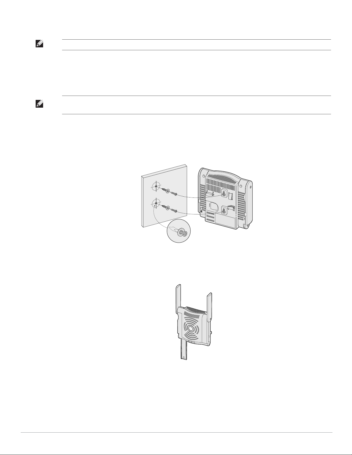
1. At the mounting location, install two screw on the wall or shelf, 1 7/8 inches (4.7 cm) apart. If you are
attaching the device to drywall, Dell recommends using appropriate wall anchors (not included).
2. Align the mounting slots on the rear of the AP over the screws and slide the unit into place (see Figure 2).
Figure 2 Installing the W-AP120 Series Access Point on a Wall
3. On the W-AP121 or W-AP125, orient the antennas. For best performance, swivel the antennas so that they
are oriented vertically, preferably in the same plane, parallel to the wall (see Figure 3).
Figure 3 Antenna Orientation on a Wall-Mounted W-AP121/W-AP125
On the W-AP120 or W-AP124, install the external antennas according to the manufacturer’s instructions,
and connect the antennas to the antenna interfaces on the AP (see Figure 4).
4 Dell PowerConnect W-AP120 Series AP | Installation Guide
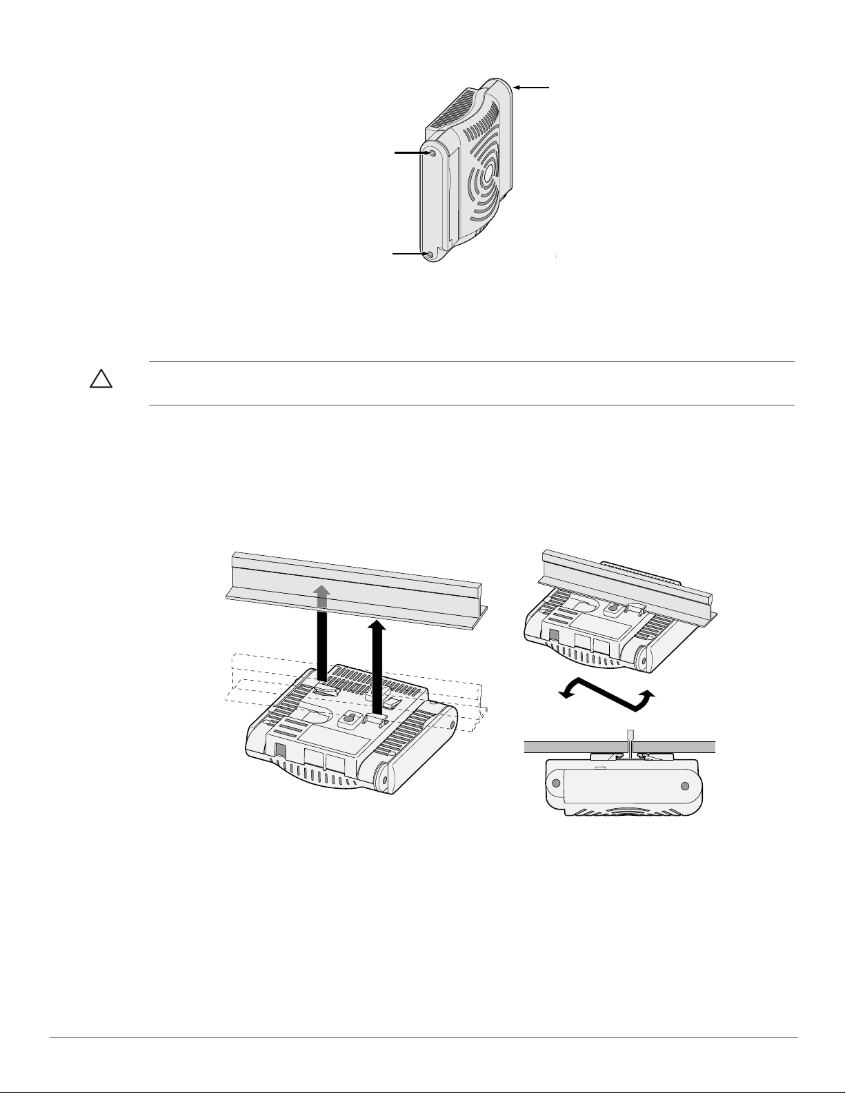
Figure 4 Antenna Interfaces on the W-AP120/W-AP124
ap
ap1
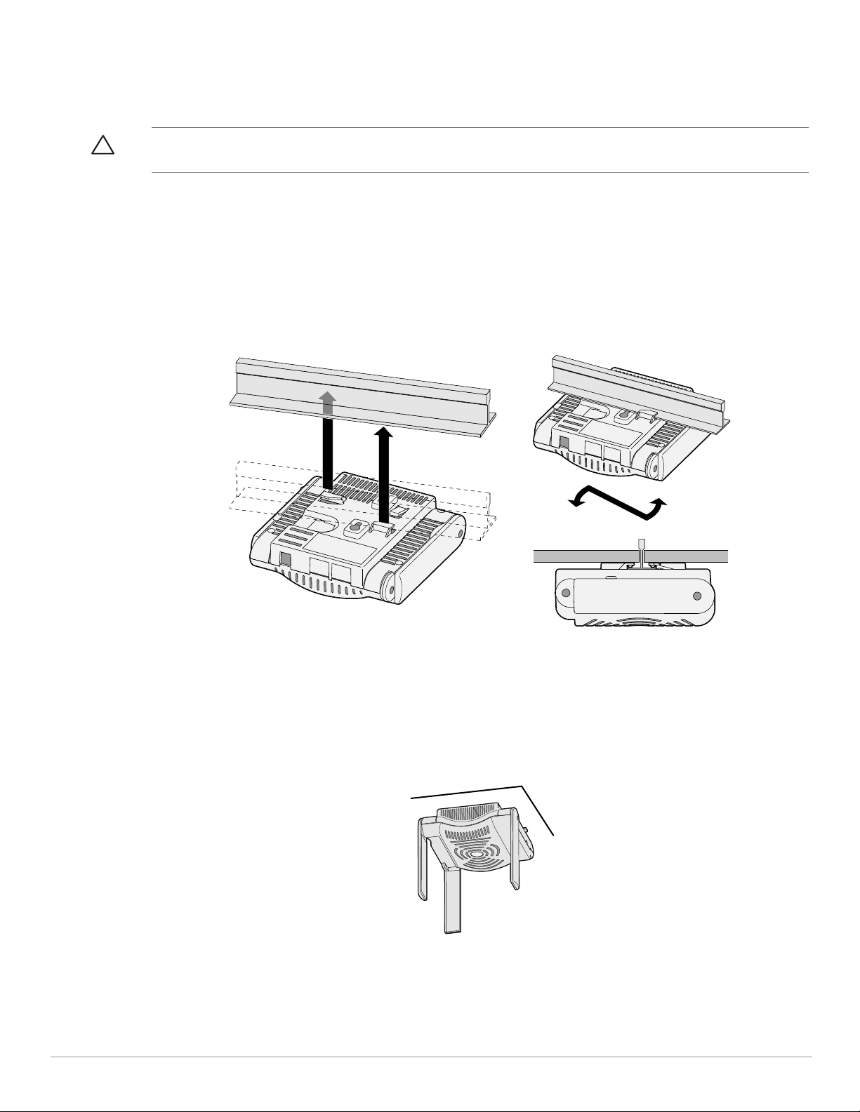
Using the Integrated Ceiling Tile Rail Slots
The snap-in tile rail slots on the rear of the AP can be used to securely attach the device directly to a 15/16" wide,
standard ceiling tile rail.
Caution: Make sure the AP fits securely on the ceiling tile rail when hanging the device from the ceiling, because poor
installation could cause it to fall onto people or equipment.
1. Pull the necessary cables through a prepared hole in the ceiling tile near where the AP will be placed.
2. If necessary, connect the console cable to the console port on the back of the AP.
3. Hold the AP next to the ceiling tile rail with the ceiling tile rail mounting slots at approximately a 30-degree
angle to the ceiling tile rail (see Figure 5). Make sure that any cable slack is above the ceiling tile.
Figure 5 Orienting the Ceiling Tile Rail Mounting Slots
4. Pushing toward the ceiling tile, rotate the AP clockwise until the device clicks into place on the ceiling tile rail.
5. On the W-AP121 or W-AP125, orient the antennas. For best results, rotate the antennas so that they are
vertical (perpendicular to the body of the AP) (see Figure 6).
Dell PowerConnect W-AP120 Series AP | Installation Guide 5
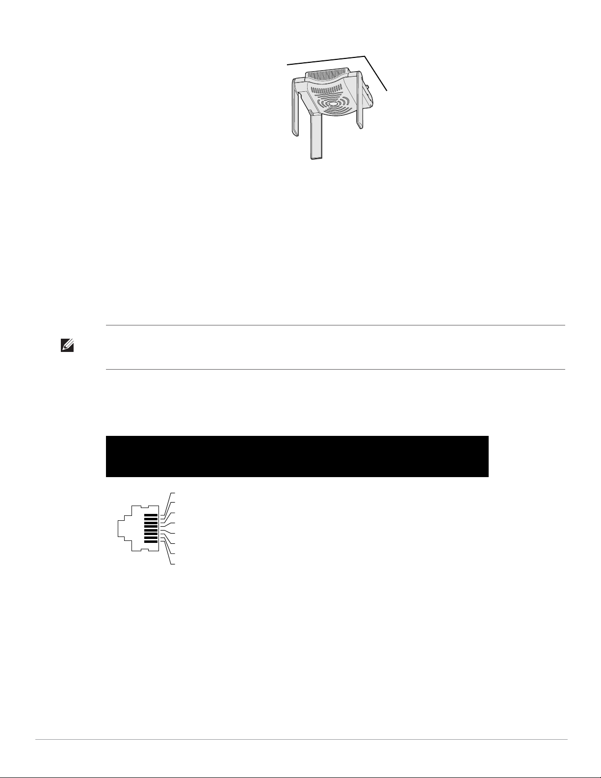
Figure 6 Antenna Orientation on a Ceiling-Mounted W-AP121/W-AP125
1
2
3
4
5
6
7
8
On the W-AP120 or W-AP124, install the external antennas according to the manufacturer’s instructions,
and connect the antennas to the antenna interfaces on the AP (see Figure 4).
Connecting Required Cables
Install cables in accordance with all applicable local and national regulations and practices.
Ethernet Ports
The RJ45 Ethernet ports (ENET0 and ENET1) support 100/1000Base-T auto-sensing MDI/MDX connections.
Use these ports to connect the AP to a twisted pair Ethernet LAN segment or directly to an Dell controller. Use a
4- or 8-conductor, Category 5 UTP cable up to 100 m (325 feet) long.
Note: Dell W-AP120 series APs are intended only for installation in Environment A as defined in IEEE 802.3.af, Power over Ethernet.
All interconnected equipment must be contained within the same building, including the interconnected equipment’s associated
LAN connections.
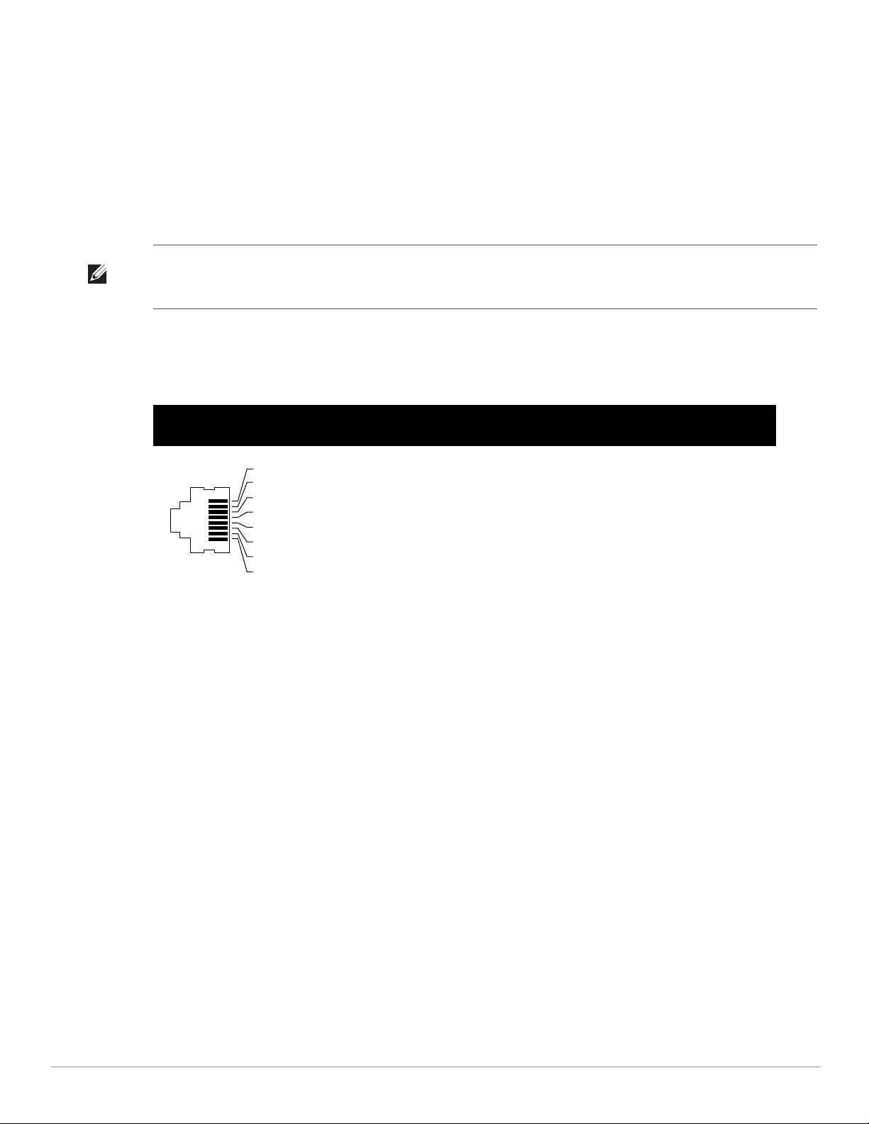
The 100/1000 Mbps Ethernet ports are on the bottom of the AP. These ports have RJ-45 female connectors with
the pin-outs shown in Table 1.
Table 1 Connector for Ethernet Ports ENET0 and ENET1
Connector Pin
1 BI_DA+ Bi-directional pair A+ RX+ POE negative
2 BI_DA– Bi-directional pair A– RX– POE negative
3 BI_DB+ Bi-directional pair B+ TX+ POE positive
4 BI_DC+ Bi-directional pair C+ Spare pair POE positive
5 BI_DC– Bi-directional pair C– Spare pair POE positive
6 BI_DB– Bi-directional pair B– TX– POE positive
Signal
Name
GE Connection
FE
Connection
PoE
7 BI_DD+ Bi-directional pair D+ Spare pair POE negative
8 BI_DB– Bi-directional pair D– Spare pair POE negative
6 Dell PowerConnect W-AP120 Series AP | Installation Guide
Serial Console Port
1
2
3
4
5
6
7
8
3
4
5
2
5
63
RJ-45 DB-9
Internal
Connections
TxD
GND
RxD
1
2
3
4
5
6
7
8
TxD
GND
RxD
RJ-45 Female
Pin-Out
Direction
Input
Output
DB-9 Male
Pin-Out
TxD
RxD
Ground
5
4
3
2
1
9
8
7
6
Direction
Input
Output
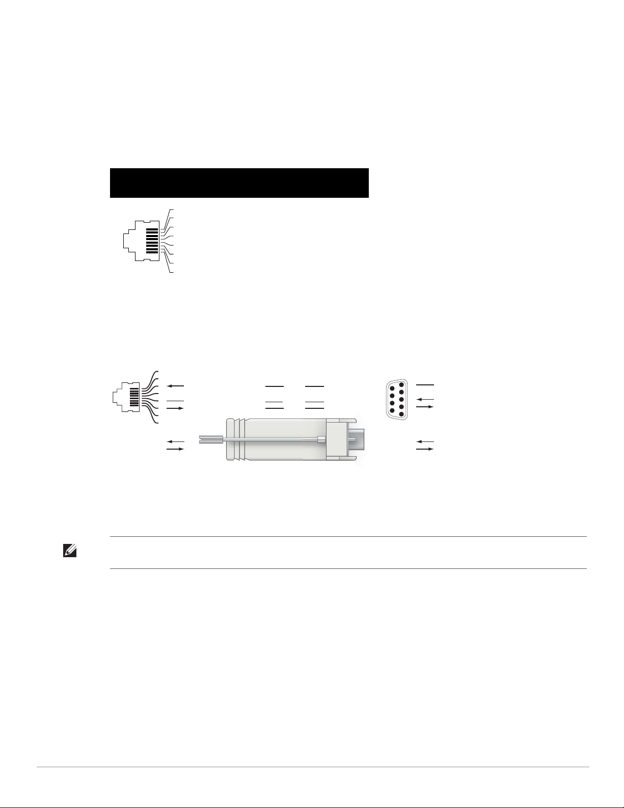
The serial console port allows you to connect the AP to a serial terminal or a laptop for direct local management.
This port is an RJ-45 female connector with the pinouts described in Table 2. Connect this port in one of the
following ways:
z Connect it directly to a terminal or terminal server using an Ethernet cable.
z Use a modular adapter to convert the RJ-45 (female) connector on the AP to a DB-9 (male) connector, and
connect the adapter to a laptop using an RS-232 cable. See Figure 7 for connector details of the adapter.
Table 2 Connector for Serial Console Port
Connector Pin Signal Name Function
3 TXD Transmit
4 GND Ground
5 GND Ground
6 RXD Receive
Pins not listed are not connected.
Figure 7 RJ-45 (Female) to DB-9 (Male) Modular Adapter Conversion
Power Connection
The W-AP120 series AP has a single 5V DC power jack socket to support powering through an AC-to-DC mains
electric power adapter.
Note: If both POE and DC power are available, the AP uses POE, even when there is not enough POE voltage available to power the
AP.
Dell PowerConnect W-AP120 Series AP | Installation Guide 7
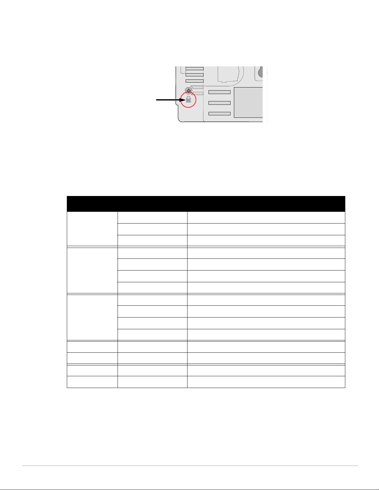
Connecting a Security Cable
To provide added security for the W-AP121 or W-AP125, you can attach a security cable to the back of the unit
(see Figure 8).
Figure 8 Security Lock Connection
Verifying Post-Installation Connectivity
The integrated LEDs on the AP can be used at this point to verify that the AP is receiving power and initializing
successfully (see Table 3). Refer to the ArubaOS Quick Start Guide for further details on verifying postinstallation network connectivity.
Table 3
LED Color/State Meaning
PWR Green steady Power on, device ready
Green flashing System initializing
Red steady System failed to initialize, contact TAC
ENET 0
(100/1000 Mbps)
ENET 1
(100/1000 Mbps)
11A/N Amber Wireless link is legacy 11a
11B/G/N Amber Wireless link is legacy 11b or 11g
Green/Amber off No link
Green on 1000 Mbps link
Amber on 100 Mbps link
Green/amber blinking Data activity
Green/Amber off No Link
Green on 1000 Mbps link
Amber on 100 Mbps link
Green/amber blinking Data activity
Green Wireless link is 11n 5 Ghz band
Green Wireless link is 11n 2.4 Ghz band
Configuring the W-AP120 Series
AP Provisioning/Reprovisioning
Provisioning parameters are unique to each AP. These local AP parameters are initially configured on the
controller which are then pushed out to the AP and stored on the AP itself. Dell recommends that provisioning
settings be configured via the ArubaOS Web UI only. Refer to the ArubaOS User Guide for complete details.
8 Dell PowerConnect W-AP120 Series AP | Installation Guide

AP Configuration
Configuration parameters are network or controller specific and are configured and stored on the controller.
Network configuration settings are pushed out to the AP(s) but remain stored on the controller.
Configuration settings can be configured via the ArubaOS Web UI, ArubaOS CLI, or Aruba MMS. Refer to their
respective guides for further details: the ArubaOS User Guide.
Product Specifications
Mechanical
z Dimensions (antenna stowed) (HxWxD):
4.9 inches x 5. 13 inches x 2 inches
12.4 cm x 13 cm x 5.1 cm
z Weight: 15 oz/0.42 kg
z Shipping Dimensions:
9.5 inches x 7.25 inches x 4.5 inches
24.1 cm x 18.4 cm x 11.4 cm
z Temperature:
Operating: 0ºC to 50ºC (32ºF to 122ºF)
Storage: –10ºC to 70ºC (14ºF to 158ºF)
Note: During normal operation, the temperature of the base of the W-AP120 series can approach 80ºC (176ºF). This is within the
expected operating temperature range.
z Relative Humidity: 5% to 95% non-condensing
z Altitude: 8,000 ft @ 28ºC (82.4ºF)
z Mounting: Wall, ceiling, or desktop mountable
z Antennas:
3 integrated articulating dual-band antenna elements (W-AP121, W-AP125)
3 RP-SMA interfaces for external antennas (W-AP120, W-AP124)
z Visual Status Indicators (LEDs): See Table 3
Electrical
Ethernet:
2 x 100/1000 Base-T auto-sensing Ethernet RJ-45 Interfaces
MDI/MDX
IEEE 802.3 (10Base-T), IEEE 802.3u (100Base-T). IEEE 802.3ab (1000Base-T)
Power over Ethernet (IEEE 802.3af compliant), 48V DC/350mA (see Table 1 for pin configuration)
z Power:
5 VDC power interface, supports powering through an AC-to-DC mains electric power adapter
Note: If a power adapter other than the one provided by Dell is used in the US or Canada, it should be cULus (NRTL) Listed, with an
output rated 5 VDC, minimum 4A, marked “LPS” or “Class 2,” and suitable for plugging into a standard power receptacle in the US
and Canada.
Dell PowerConnect W-AP120 Series AP | Installation Guide 9

POE support on Ethernet ports:
– 802.3af-compliant POE sourcing devices
– POE+ (56 V @ 350 mA)
Wireless LAN
z Network Standards: IEEE 802.11b, IEEE 802.11g, IEEE 802.11a, and IEEE 802.11n (draft)
z Antenna Type:
Integrated 802.11a/b/g/n omni-directional high-gain antenna
Detachable 802.11a/b/g/n omni-directional high-gain antenna
z Antenna Gain (Integrated Antennas):
2.4 – 2.5 GHz/3.2 dBi (max)
5.180 – 5.825 GHz/5.2 dBi (max)
z Radio Technology:
Orthogonal Frequency Division Multiplexing (OFDM)
Direct Sequence Spread Spectrum (DSSS)
z Radio Modulation Type:
802.11b - CCK, BPSK, QPSK
802.11g - CCK, BPSK, QPSK,16-QAM, 64-QAM
802.11a - BPSK, QPSK,16-QAM, 64-QAM
802.11n draft 2.0
z Media Access Control: CSMA/CA with ACK
z Supported Frequency Bands 2.4GHz:
2.400 ~ 2.4835GHz (Global), channels country specific
z Supported Frequency Bands 5GHz:
5.150 ~ 5.250GHz (low band), country-specific
5.250 ~ 5.350GHz (mid band), country-specific
5.470 ~ 5.725GHz (Europe), country-specific
5.725 ~ 5.825GHz GHz (high band), country-specific
802.11b 802.11g 802.11a 802.11n
US, Canada 11 US, Canada 11 US, Canada 12 << NEED >>
ETSI 13 ETSI 13 ETSI (up to 19) << NEED >>
Japan 14 Japan 13 Japan 4 << NEED >>
Taiwan 11 Taiwan 11 Taiwan 7 << NEED >>
z Data Rates:
802.11b - 1, 2, 5.5, 11 Mbps per channel
802.11g - 6, 9, 12, 18, 24, 36, 48 and 54 Mbps per channel
802.11a - 6, 9, 12, 18, 24, 36, 48 and 54 Mbps per channel
802.11n - Data rate MCS0 – MCS15 (from 6.5 Mbps to 300 Mbps)
10 Dell PowerConnect W-AP120 Series AP | Installation Guide
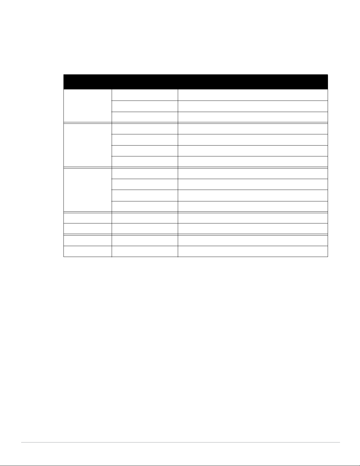
Proper Disposal of Dell Equipment
Radio Equipment for the radio data communication system
** Warning Notice **
㩷
For a radio equipment using 2400~2483.5MHz or 5725~5825MHz,
the following two expression should be displayed ;
1. Indicate following expression on the product where is easy to see : “This
radio equipment can be crossed during operation.”
㩷
䚨㩷 ⱨ㉔㉘⽸⏈㩷 㟨㟝㩷 㩅㩷 㤸䑀䝰㐔㩷 ᴴ⏙㉥㢨㩷 㢼㢀㩷
㩷
2. The manufacturer and installer should fully inform the operator or users “This
radio equipment cannot provide a service relevant to the human life safety, as it
can be crossed” through the user manual etc.
㩷
䚨㩷 ⱨ㉔㉘⽸ 㤸䑀䝰㐔 ᴴ⏙㉥㢨㩷 㢼㡰⦐㩷 㢬⮹㙼㤸Ḱ㩷 Ḵ⥜═㩷 ㉐⽸㏘⏈㩷 䚔㩷 ㍌㩷 㛺㏩⏼␘㪅㩷
For the most current information on Global Environmental Compliance and Dell products please refer to the
Dell PowerConnect W-Series Safety, Environmental, and Regulatory Information document is included with this
product or see our website at www.dell.com.
European Union RoHS
Aruba products also comply with the EU Restriction of Hazardous Substances Directive
2002/95/EC (RoHS). EU RoHS restricts the use of specific hazardous materials in the
manufacture of electrical and electronic equipment. Specifically, restricted materials
under the RoHS Directive are Lead (including Solder used in printed circuit assemblies), Cadmium, Mercury,
Hexavalent Chromium, and Bromine. Some Aruba products are subject to the exemptions listed in RoHS
Directive Annex 7 (Lead in solder used in printed circuit assemblies). Products and packaging will be marked
with the “RoHS” label shown at the left indicating conformance to this Directive.
Battery Replacement
Caution: Batteries included with Dell products must be replaced by qualified Dell service personnel only. Contact Dell for battery
replacement. Do not attempt to replace the battery. There is a risk of explosion if you install the wrong type of battery. Dispose of
batteries according to the instructions.
Safety and Regulatory Compliance
Dell provides a multi-language document containing country specific restrictions and additional safety and
regulatory information for all Dell hardware products. The Dell PowerConnect W-Series Safety, Environmental,
and Regulatory Information document is included with this product.
Caution: RF Radiation Exposure Statement: This equipment complies with FCC RF radiation exposure limits. This equipment
should be installed and operated with a minimum distance of 13.78 inches (35 cm) between the radiator and your body for 2.4 GHz
and 5 GHz operations. This transmitter must not be co-located or operating in conjunction with any other antenna or transmitter.
When operated in the 5.15 to 5.25 GHz frequency range, this device is restricted to indoor use to reduce the potential for harmful
interference with co-channel Mobile Satellite Systems.
Korean Radio Equipment Warning Notice
Dell PowerConnect W-AP120 Series AP | Installation Guide 11

Copyright
© 2010 Aruba Networks, Inc. AirWave®, Aruba Networks®, Aruba Mobility Management System®, Bluescanner, For
Wireless That Works®, Mobile Edge Architecture®, People Move. Networks Must Follow®, RFprotect®, The All
Wireless Workplace Is Now Open For Business, Green Island, and The Mobile Edge Company® and other registered
marks are trademarks of Aruba Networks, Inc. Dell™, the DELL™ logo, and PowerConnect™ are trademarks of Dell
Inc.
All rights reserved. Specifications in this manual are subject to change without notice.
Originated in the USA. Any other trademarks appearing in this manual are the property of their respective companies.
Open Source Code
Certain Aruba products include Open Source software code developed by third parties, including software code
subject to the GNU General Public License (GPL), GNU Lesser General Public License (LGPL), or other Open Source
Licenses. The Open Source code used can be found at this site:
http://www.arubanetworks.com/open_source
Legal Notice
The use of Aruba Networks, Inc. switching platforms and software, by all individuals or corporations, to terminate
other vendors' VPN client devices constitutes complete acceptance of liability by that individual or corporation for
this action and indemnifies, in full, Aruba Networks, Inc. from any and all legal actions that might be taken against it
with respect to infringement of copyright on behalf of those vendors.
Warranty
This hardware product is protected by the standard Aruba warranty of one year parts/labor. For more information,
refer to the ARUBACARE SERVICE AND SUPPORT TERMS AND CONDITIONS.
Altering this device (such as painting it) voids the warranty.
12 Dell PowerConnect W-AP120 Series AP | Installation Guide
Dell PowerConnect W-AP120 Serie AP
ap12_001
W-AP120/W-AP124
W-AP121/W-AP125
(3 x integrierte Dualband-Antennen)
Installationsanleitung
Installationsanleitung
Die drahtlosen Access Points der Serie Dell W-AP120 unterstützen den zukünftigen Standard IEEE 802.11n
(zurzeit Entwurf 2.0) für Hochleistungs-WLANs. Diese Access Points verwenden die MIMO-Technologie
(Multiple-In, Multiple-Out) und andere Techniken mit hohem Durchsatz, um Hochleistungs-, Prä-802.11nFunktionalität mit 2,4 GHz und 5 GHz zu bieten, während gleichzeitig vorhandene 802.11a/b/g-Drahtlosdienste
unterstützt werden. Die Access Points der Serie W-AP120 sind in Versionen mit Einzel- oder Dualfunk sowie mit
integrierten Antennen oder RP-SMA-Schnittstellen zur Unterstützung abnehmbarer Antennen erhältlich.
Die Access Points der Serie W-AP120 können nur zusammen mit einem Dell Controller verwendet werden.
Die Access Points der Serie Dell W-AP120 weisen die folgenden Merkmale auf:
z Drahtloser Transceiver
z Protokollunabhängige Netzwerkfunktionalität
z Betrieb gemäß IEEE 802.11a/b/g oder 802.11n als drahtloser Access Point
z Betrieb gemäß IEEE 802.11a/b/g oder 802.11n als drahtloser Air Monitor
z Kompatibilität mit IEEE 802.3af PoE sowie der Vornorm für High Power over Ethernet (PoE + / 802.3at)
z Zentrale Verwaltungskonfiguration und Upgrades über einen Dell Controller
z Upgrade von a/b/g-Modellen der Serie W-AP120 auf Konformität mit 802.11n (Entwurf) über eine
Controllerlizenz
Abbildung 1 Access Points der Serie W-AP120
0510745-MU-01 | Juli 2010 1

Lieferumfang
z AP-120 Serie Access Point
z Installationsanleitung (dieses Dokument)
Hinweis: Wenden Sie sich an Ihren Händler, wenn Teile fehlen oder beschädigt sind oder wenn Sie falsche Teile erhalten haben.
Bewahren Sie den Karton einschließlich der Original-Verpackungsmaterialien nach Möglichkeit auf. Verwenden Sie diese
Materialien, um das Produkt bei Bedarf zu verpacken und zum Händler zurückzubringen.
Hinweis: Zusätzliche Montage-Sets zur Verwendung mit Access Points der Serie W-AP120 sind separat erhältlich.
Wenden Sie sich an Ihren Dell-Kundenbetreuer, falls Sie nähere Informationen wünschen.
Bevor Sie beginnen
WLAN-Planung
Stellen Sie fest, wie viele Dell APs für die Bereitstellung Ihres drahtlosen Netzwerks erforderlich sind und wo sie
installiert werden sollen. Diese Planung wird durch die Dell-Software für die automatisierte Funkplan-SiteÜbersicht (separat erhältlich) vereinfacht. Dieser Prozess wird als WLAN- oder Funkplanung bezeichnet und
sollte während der Installation und Konfiguration des Dell Controllers (Master) abgeschlossen worden sein.
In typischen Dell-Installationen werden die Controller vor den APs konfiguriert und installiert.
Informationen zur WLAN-Planung finden Sie in den Handbüchern Indoor Access Points: Site Survey and
Planning Pre-Deployment Guide und RF Plan Installation and User Guide.
Netzwerkvoraussetzungen vor der Installation
Nachdem die WLAN-Planung abgeschlossen ist und die entsprechenden Produkte sowie deren Platzierung
bestimmt wurden, müssen die Dell Controller installiert und erstmals eingerichtet werden, bevor die Dell Access
Points bereitgestellt werden können.
Informationen zur erstmaligen Einrichtung der Controller finden Sie im Handbuch ArubaOS Quick Start Guide
für die auf Ihren Controllern installierte Softwareversion.
Vor der Installation - Checkliste
Stellen Sie vor der Installation des Access Points der Serie W-AP120 sicher, dass Folgendes zur Hand ist:
z Für den W-AP120/W-AP124: Externe Antennen wie im Netzwerkbereitstellungsplan angegeben
z CAT5 UTP-Kabel in der erforderlichen Länge
z Eine der folgenden Stromquellen:
IEEE 802.3af-konforme PoE-Quelle (Power over Ethernet)
Unterstützt volle Funktionalität für W-AP120/W-AP121; unterstützt eingeschränkte Funktionalität für
W-AP124/W-AP125
IEEE Power Over Ethernet + (PoE+) Ausgabe mit 56 Volt @ 350 mA
Die PoE-Quelle kann ein beliebiger PSE-Controller (PSE = Power Sourcing Equipment,
Energieversorger) oder ein Midspan-PSE-Gerät sein.
Dell AP AC-DC-Adapter-Kit (separat erhältlich)
z Im Netzwerk bereitgestellter Dell Controller:
Layer-2/3-Netzwerkkonnektivität zum Access Point
Einer der folgenden Netzwerkdienste:
2 Dell PowerConnect W-AP120 Serie AP | Installationsanleitung

z Aruba Discovery Protocol (ADP)
z DNS-Server mit einem „A“-Record
z DHCP-Server mit herstellerspezifischen Optionen
Übersicht über den Einrichtungsprozess
Hinweis: Es ist wichtig, dass Sie die unter Vor der Installation - Checkliste aufgeführten Punkte überprüfen, bevor Sie versuchen,
einen AP der Serie W-AP120 einzurichten und zu installieren.
Um den AP-120 Serie Access Point erfolgreich zu installieren, müssen die folgenden fünf Schritte in der
angegebenen Reihenfolge durchgeführt werden:
1. Überprüfen der Konnektivität vor der Installation.
2. Festlegen des Installationsstandorts für die einzelnen APs.
3. Installieren der einzelnen APs.
4. Überprüfen der Konnektivität nach der Installation.
5. Konfigurieren der einzelnen APs.
Hinweis: Dell hat in Übereinstimmung mit den behördlichen Vorschriften die AP-120 Serie Access Points so konzipiert, dass nur
autorisierte Netzwerkadministratoren die Einstellungen ändern können. Weitere Informationen zur AP-Konfiguration finden Sie im
ArubaOS Quick Start Guide und Aruba OS User Guide.
Vorsicht: Access Points sind Funkübertragungsgeräte und unterliegen als solche behördlichen Regulierungen.
Netzwerkadministratoren, die für die Konfiguration und den Betrieb von Access Points verantwortlich sind, müssen die örtlich
geltenden Funkvorschriften einhalten. Insbesondere müssen Access Points Kanalzuweisungen verwenden, die für die
Umgebung, in der der Access Point genutzt wird, angemessen sind.
Überprüfen der Konnektivität vor der Installation
Bevor Sie APs in einer Netzwerkumgebung installieren, sollten Sie sicherstellen, dass die APs den Controller
erkennen und eine Verbindung dazu herstellen können, wenn sie eingeschaltet sind.
Sie müssen speziell die folgenden Bedingungen überprüfen:
z Wenn eine Verbindung zum Netzwerk hergestellt wurde, wird jedem AP eine gültige IP-Adresse zugewiesen
z APs können den Controller erkennen
Anweisungen zum Erkennen und zum Herstellen der Verbindung zum Controller finden Sie im Handbuch
ArubaOS Quick Start.
Festlegen der spezifischen Installationsstandorte
Sie können den AP-120 Serie Access Point an einer Wand oder unter der Decke anbringen. Orientieren Sie sich
an der AP-Platzierungsübersicht, die von der Dell-Software für die Funkplanung generiert wurde, um die
richtigen Installationsorte zu bestimmen. Jeder Installationsort sollte sich so nah wie möglich an der Mitte des
beabsichtigten Abdeckungsbereichs befinden und sollte weder Hindernisse noch offensichtliche Störungsquellen
aufweisen. Diese Funk-Dämpfer/Reflektoren/Störungsquellen beeinträchtigen die Verbreitung der Funkwellen
und sollten in der Planungsphase berücksichtigt und ausgeglichen worden sein.
Dell PowerConnect W-AP120 Serie AP | Installationsanleitung 3

Nicht identifizierte bekannte Funk-Dämpfer/Reflektoren/Störungsquellen
Es ist sehr wichtig, während der Installationsphase vor Ort nach Elementen zu suchen, die als Funkdämpfer oder
-reflektoren bzw. als Störungsquellen bekannt sind. Achten Sie darauf, dass diese Elemente berücksichtig werden,
wenn Sie einen AP an seinem festen Standort anbringen.
Beispiele für Funkdämpfer:
z Zement/Beton: Alter Beton gibt viel Wasser ab, wodurch der Beton ausgetrocknet wird, was die Ausbreitung
von Funkwellen ermöglicht. Neuer Beton bindet viel Wasser, sodass Funksignale blockiert werden.
z Natürliche Elemente: Aquarien, Brunnen, Teiche und Bäume
z Ziegelwände
Beispiele für Funkreflektoren:
z Metallobjekte: Metallplatten zwischen Stockwerken, Betonrippenstahl, Feuertüren, Klimaanlagen- und
Heizungsschächte, mit Draht verstärkte Fenster, Jalousien, Maschendrahtzäune (je nach Maschengröße),
Kühlschränke, Gestelle, Regale und Aktenschränke
z Platzieren Sie APs nicht zwischen zwei Klimaanlangen-/Heizungsschächten. Achten Sie darauf, dass APs
unter solchen Schächten platziert werden, um Funkstörungen zu vermeiden.
Beispiele für Funkstörungsquellen:
z Mikrowellengeräte und andere 2,4- oder 5-GHz-Objekte (zum Beispiel schnurlose Telefone)
z Kantinen und Telefonzentralen mit schnurlosen Headsets
Installieren der APs
Hinweis: Arbeiten an Dell-Produkten dürfen nur von geschultem Servicepersonal ausgeführt werden.
Verwenden der integrierten Öffnungen für die Wandmontage
Mithilfe der schlüssellochförmigen Öffnungen auf der Rückseite des APs kann das Gerät aufrecht an einer Wand
oder einem Regal im Innenbereich angebracht werden. Achten Sie bei der Auswahl der Montageposition darauf,
dass rechts neben der Einheit noch ausreichend Platz für Kabel ist.
Hinweis: Die Abmessungen des Produkts finden Sie unter Produktspezifikationen in dieser Anleitung. Lassen Sie rechts neben
dem befestigten Gerät 5 cm Platz für Kabel und achten Sie darauf, dass genügend Platz für die Ausrichtung der Antenne
vorhanden ist.
1. Bringen Sie an der Montageposition zwei Schrauben im Abstand von 4,7 cm an der Wand oder am Regal an.
Wenn Sie das Gerät an einer Trockenbauwand anbringen, empfiehlt Dell die Verwendung von geeigneten
Dübeln (nicht im Lieferumfang enthalten).
2. Richten Sie die Montageöffnungen auf der Rückseite des APs über den Schrauben aus und schieben Sie die
Einheit an ihre Position (siehe Abbildung 2).
4 Dell PowerConnect W-AP120 Serie AP | Installationsanleitung
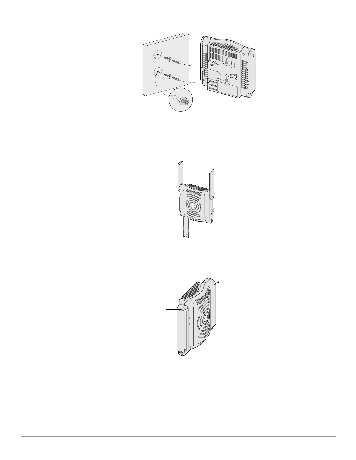
Abbildung 2 Installation des Access Points der Serie W-AP120 an einer Wand
ap
3. Richten Sie die Antennen am W-AP121 oder W-AP125 aus. Um die optimale Leistung zu erzielen, richten
Sie die Antennen so aus, dass sie vertikal, möglichst auf derselben Ebene, parallel zur Wand ausgerichtet sind
(siehe Abbildung 3).
Abbildung 3 Antennenausrichtung für einen wandmontierten W-AP121/W-AP125
Installieren Sie beim W-AP120 oder W-AP124 die externen Antennen gemäß den Anweisungen des
Herstellers und schließen Sie die Antennen an die Antennenschnittstellen am AP an (siehe Abbildung 4).
Abbildung 4 Antennenschnittstellen am W-AP120/W-AP124
Dell PowerConnect W-AP120 Serie AP | Installationsanleitung 5
Verwenden der integrierten Befestigungen für die Deckenschiene
ap1
Mit den Schnappvorrichtungen für die Deckenmontage auf der Rückseite des APs kann das Gerät sicher direkt an
einer 15/16 Zoll breiten, standardmäßigen Deckenplattenschiene befestigt werden.
Vorsicht: Achten Sie darauf, dass der AP sicher auf der Schiene sitzt, wenn Sie das Gerät an die Decke hängen, da es bei
unsachgemäßer Befestigung herunterfallen und Personen verletzen oder Sachschäden verursachen könnte.
1. Führen Sie die erforderlichen Kabel durch ein vorbereitetes Loch in der Deckenplatte in der Nähe der für den
AP vorgesehenen Position.
2. Falls erforderlich, schließen Sie das Konsolenkabel an die Konsolenschnittstelle auf der Rückseite des APs an.
3. Halten Sie den AP an die Deckenschiene, wobei sich die Vorrichtungen für die Anbringung an der
Deckenschiene in einem Winkel von ungefähr 30 Grad zur Schiene befinden sollten (siehe Abbildung 5).
Achten Sie darauf, dass sich etwaige Kabelschlaufen über der Deckenplatte befinden.
Abbildung 5 Ausrichtung der Befestigungsvorrichtungen für die Deckenmontage
4. Drehen Sie den AP mit Druck in Richtung Decke im Uhrzeigersinn, bis das Gerät in der Deckenschiene
einrastet.
5. Richten Sie die Antennen am W-AP121 oder W-AP125 aus. Die besten Ergebnisse erzielen Sie, wenn Sie
die Antennen so drehen, dass sie sich in einer vertikalen Position (senkrecht zum AP) befinden
(siehe Abbildung 6).
Abbildung 6 Antennenausrichtung für einen deckenmontierten W-AP121/W-AP125
Installieren Sie beim W-AP120 oder W-AP124 die externen Antennen gemäß den Anweisungen des
Herstellers und schließen Sie die Antennen an die Antennenschnittstellen am AP an (siehe Abbildung 4).
6 Dell PowerConnect W-AP120 Serie AP | Installationsanleitung
Anschließen der erforderlichen Kabel
1
2
3
4
5
6
7
8
Schließen Sie Kabel immer in Übereinstimmung mit allen örtlichen und nationalen Vorschriften und
Richtlinien an.
Ethernet-Schnittstellen
Die RJ45-Ethernet-Schnittstellen (ENET0 und ENET1) unterstützen 100/1000Base-T-Verbindungen mit
automatischer Erkennung und MDI/MDX. Verwenden Sie diese Schnittstellen, um den AP an ein Twisted-PairEthernet-LAN-Segment oder direkt an einen Dell Controller anzuschließen. Stellen Sie die Verbindung über ein
4- oder 8-adriges UTP-Kabel der Kategorie 5 (CAT5) her, das bis zu 100 m lang sein kann.
Hinweis: APs der Serie Dell W-AP120 dürfen nur in Umgebung A gemäß Definition in IEEE 802.3.af, Power over Ethernet installiert
werden. Alle verbundenen Geräte müssen sich in demselben Gebäude befinden, dies gilt auch für die zugeordneten LANVerbindungen der verbundenen Geräte.
Die Schnittstellen für 100/1000-Mbit/s-Ethernet befinden sich auf der Unterseite des AP. Diese Schnittstellen
haben RJ-45-Buchsen mit der in Tabelle 1 dargestellten Pin-Belegung.
Tabelle 1 Anschluss für Ethernet-Schnittstellen ENET0 und ENET1
Anschluss Pin Signalname GE-Verbindung FE-Verbindung PoE
1 BI_DA+ Bidirektionales Paar A+ RX+ PoE negativ
2 BI_DA– Bidirektionales Paar A– RX– PoE negativ
3 BI_DB+ Bidirektionales Paar B+ TX+ PoE positiv
4 BI_DC+ Bidirektionales Paar C+ Reservepaar PoE positiv
5 BI_DC– Bidirektionales Paar C– Reservepaar PoE positiv
6 BI_DB– Bidirektionales Paar B– TX– PoE positiv
7 BI_DD+ Bidirektionales Paar D+ Reservepaar PoE negativ
8 BI_DB– Bidirektionales Paar D– Reservepaar PoE negativ
Serielle Konsolenschnittstelle
Die serielle Konsolenschnittstelle ermöglicht den Anschluss des APs an ein serielles Terminal oder an ein
Laptop zur direkten lokalen Verwaltung. Bei dieser Schnittstelle handelt es sich um eine RJ-45-Buchse mit der
in Tabelle 2 dargestellten Pin-Belegung. Stellen Sie auf eine der folgenden Weisen eine Verbindung mit dieser
Schnittstelle her:
z Schließen Sie sie über ein Ethernet-Kabel direkt an ein Terminal oder einen Terminalserver an.
z Verwenden Sie einen modularen Adapter, um die RJ-45-Buchse am AP in einen DB-9-Stecker umzuwandeln,
und schließen Sie den Adapter über ein RS-232-Kabel an ein Laptop an. Anschlussdetails des Adapters
können Sie Abbildung 7 entnehmen.
Dell PowerConnect W-AP120 Serie AP | Installationsanleitung 7
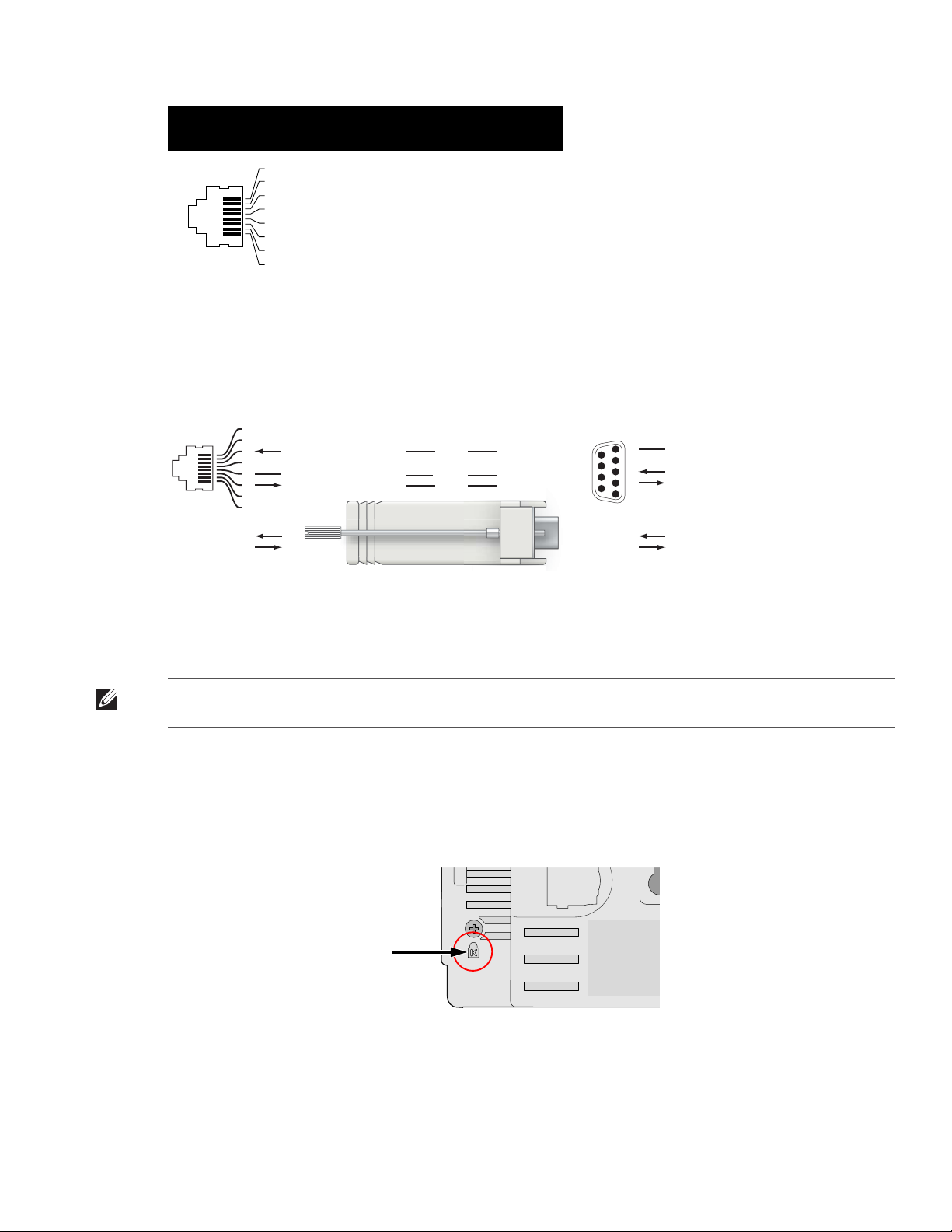
Tabelle 2 Stecker für die serielle Konsolenschnittstelle
1
2
3
4
5
6
7
8
3
4
5
2
5
63
RJ-45 DB-9
Interne
Verbindungen
TxD
GND
RxD
1
2
3
4
5
6
7
8
TxD
GND
RxD
RJ-45-Buchse
Pin-Belegung
Richtung
Eingang
Ausgang
DB-9-Stecker
Pin-Belegung
TxD
RxD
Masse
5
4
3
2
1
9
8
7
6
Richtung
Eingang
Ausgang
Anschluss Pin Signalname Funktion
3 TXD Senden
4GND Masse
5GND Masse
6 RXD Empfangen
Nicht aufgeführte Pins sind nicht
angeschlossen.
Abbildung 7 Umwandlung der RJ-45-Buchse zum DB-9-Stecker mit modularem Adapter
Stromversorgung
Die APs der Serie W-AP120 verfügen über einen 5-V-Gleichstrom-Anschluss für die Stromversorgung über einen
Netzadapter (Wechselstrom-zu-Gleichstrom).
Hinweis: Sind sowohl PoE als auch Gleichstrom verfügbar, verwendet der AP PoE, selbst wenn nicht ausreichend PoE-Spannung
für die Versorgung des APs vorhanden ist.
Anschließen eines Sicherheitskabels
Um den W-AP121 oder W-AP125 besser zu sichern, können Sie ein Sicherheitskabel auf der Rückseite des
Geräts anschließen (siehe Abbildung 8).
Abbildung 8 Vorrichtung für ein Sicherheitskabel
8 Dell PowerConnect W-AP120 Serie AP | Installationsanleitung
Überprüfen der Konnektivität nach der Installation
Mit den integrierten LEDs am AP kann jetzt überprüft werden, ob der AP mit Energie versorgt wird und
erfolgreich initialisiert wurde (siehe Tabelle 3). Weitere Informationen zur Überprüfung der
Netzwerkkonnektivität nach der Installation finden Sie im ArubaOS Quick Start Guide.
Tabelle 3
LED Farbe/Status Bedeutung
PWR Grün, konstant Eingeschaltet, Gerät bereit
Grün, blinkend System wird initialisiert
Rot, konstant System konnte nicht initialisiert werden, TAC benachrichtigen
ENET 0
(100/1000 Mbit/s)
ENET 1
(100/1000 Mbit/s)
11A/N Gelb Wireless-Verbindung ist Legacy 11a
11B/G/N Gelb Wireless-Verbindung ist Legacy 11b oder 11g
Grün/Gelb, aus Keine Verbindung
Grün, ein Verbindung mit 1000 Mbit/s
Gelb, ein Verbindung mit 100 Mbit/s
Grün/Gelb, blinkend Datenaktivität
Grün/Gelb, aus Keine Verbindung
Grün, ein Verbindung mit 1000 Mbit/s
Gelb, ein Verbindung mit 100 Mbit/s
Grün/Gelb, blinkend Datenaktivität
Grün Wireless-Verbindung ist 11n 5-GHz-Band
Grün Wireless-Verbindung ist 11n 2,4-GHz-Band
Konfiguration der Serie W-AP120
AP-Provisioning/-Reprovisioning
Die Parameter für das Provisioning (Versorgungsprozess) sind für jeden AP einzigartig. Diese lokalen APParameter werden erstmalig auf dem Controller konfiguriert und dann auf den AP geleitet und dort gespeichert.
Dell empfiehlt, die Provisioning-Einstellungen nur über die ArubaOS-Web-UI zu konfigurieren. Ausführliche
Informationen finden Sie im ArubaOS User Guide.
AP-Konfiguration
Die Konfigurationsparameter sind netzwerk- oder Controllerspezifisch und werden auf dem Controller
konfiguriert und gespeichert. Die Einstellungen für die Netzwerkkonfiguration werden an den AP bzw. die APs
weitergegeben, sie bleiben jedoch im Speicher des Controllers.
Die Konfigurationseinstellungen lassen sich über die ArubaOS Web-UI, ArubaOS CLI oder Aruba MMS
vornehmen. Weitere Informationen finden Sie in den entsprechenden Handbüchern: ArubaOS User Guide.
Dell PowerConnect W-AP120 Serie AP | Installationsanleitung 9

Produktspezifikationen
Mechanisch
z Abmessungen (Antenne eingefahren) (HxBxT):
12,4 cm x 13 cm x 5,1 cm
z Gewicht: 0,42 kg
z Versandmaße:
24,1 cm x 18,4 cm x 11,4 cm
z Temperatur:
Betrieb: 0ºC bis 50ºC
Lagerung: –10ºC bis 70ºC
Hinweis: Bei normalem Betrieb kann die Temperatur an der Unterseite der Serie W-AP120 80ºC erreichen. Dies liegt innerhalb des
erwarteten Betriebstemperaturbereichs.
z Relative Luftfeuchtigkeit: 5 % bis 95 %, nicht kondensierend
z Höhe: 2438 m bei 28ºC
z Montage: Wand, Decke oder Schreibtisch
z Antennen:
3 integrierte bewegliche Dualbank-Antennenelemente (W-AP121, W-AP125)
3 RP-SMA-Schnittstellen für externe Antennen (W-AP120, W-AP124)
z Optische Statusanzeigen (LEDs): Siehe Tabelle 3
Elektrisch
Ethernet:
2 x 100/1000 Base-T Ethernet-RJ-45-Schnittstellen mit automatischer Erkennung
MDI/MDX
IEEE 802.3 (10Base-T), IEEE 802.3u (100Base-T) IEEE 802.3ab (1000Base-T)
Power over Ethernet (IEEE 802.3af-konform), 48 V DC/350 mA (Pin-Konfiguration siehe Tabelle 1)
z Stromversorgung:
5-VDC-Schnittstelle, unterstützt Stromversorgung über einen Netzadapter (Wechselstrom-zu-
Gleichstrom)
Hinweis: Wenn in den USA oder in Kanada ein anderer Netzadapter als der von Dell bereitgestellte verwendet wird, sollte er das
cULus (NRTL)-Kennzeichen tragen, mit einer Nennausgabe von 5 VDC, mindestens 4 A, Kennzeichnung „LPS“ oder „Class 2“,
geeignet für den Anschluss an eine in den USA und in Kanada übliche Standardsteckdose.
PoE-Unterstützung an Ethernet-Schnittstellen:
– 802.3af-konforme PoE-Sourcing-Geräte
– POE+ (56 V @ 350 mA)
10 Dell PowerConnect W-AP120 Serie AP | Installationsanleitung

Wireless LAN
z Netzwerkstandards: IEEE 802.11b, IEEE 802.11g, IEEE 802.11a und IEEE 802.11n (Entwurf)
z Antennentyp:
Integrierte 802.11a/b/g/n omnidirektionale High-Gain-Antenne
Abnehmbare 802.11a/b/g/n omnidirektionale High-Gain-Antenne
z Antennengewinn (integrierte Antennen):
2,4 – 2,5 GHz/3,2 dBi (max.)
5,180 – 5,825 GHz/5,2 dBi (max.)
z Funktechnologie:
Orthogonal Frequency Division Multiplexing (OFDM)
Direct Sequence Spread Spectrum (DSSS)
z Funkmodulationstyp:
802.11b - CCK, BPSK, QPSK
802.11g - CCK, BPSK, QPSK,16-QAM, 64-QAM
802.11a - BPSK, QPSK,16-QAM, 64-QAM
802.11n Entwurf 2.0
z Media Access Control (MAC): CSMA/CA mit ACK
z Unterstützte Frequenzbänder 2,4 GHz:
2,400 ~ 2,4835 GHz (global), Kanäle landesspezifisch
z Unterstützte Frequenzbänder 5 GHz:
5,150 ~ 5,250 GHz (Low-Band), landesspezifisch
5,250 ~ 5,350 GHz (Mid-Band), landesspezifisch
5,470 ~ 5,725 GHz (Europa), landesspezifisch
5,725 ~ 5,825 GHz (High-Band), landesspezifisch
802.11b 802.11g 802.11a 802.11n
USA, Kanada 11 USA, Kanada 11 USA, Kanada 12 << NEED >>
ETSI 13 ETSI 13 ETSI (bis zu 19) << NEED >>
Japan 14 Japan 13 Japan 4 << NEED >>
Taiwan 11 Taiwan 11 Taiwan 7 << NEED >>
z Datenraten:
802.11b - 1, 2, 5,5, 11 Mbit/s pro Kanal
802.11g - 6, 9, 12, 18, 24, 36, 48 und 54 Mbit/s pro Kanal
802.11a - 6, 9, 12, 18, 24, 36, 48 und 54 Mbit/s pro Kanal
802.11n - Datenrate MCS0 – MCS15 (von 6,5 Mbit/s bis 300 Mbit/s)
Dell PowerConnect W-AP120 Serie AP | Installationsanleitung 11
Ordnungsgemäße Entsorgung von Dell-Geräten
Die aktuellsten Informationen zur Konformität mit globalen Umweltschutzrichtlinien und Dell-Produkten
finden Sie im Dokument Dell PowerConnect W-Series Safety, Environmental, and Regulatory Information, das Sie
mit diesem Produkt erhalten haben, oder auf unserer Website unter www.dell.com.
RoHS-Richtlinie der Europäischen Union
Aruba-Produkte erfüllen auch die RoHS-Richtlinie 2002/95/EC (Restriction of Hazardous
Substances, Beschränkung gefährlicher Substanzen). Die RoHS-Richtlinie der EU
schränkt die Verwendung gefährlicher Substanzen bei der Herstellung von elektrischen
und elektronischen Produkten ein. Insbesondere Blei (einschließlich Lötzinn in elektronischen Leiterplatten),
Cadmium, Quecksilber, sechswertiges Chrom und Brom gehören laut RoHS-Richtlinie zu den
einzuschränkenden Werkstoffen. Für einige Aruba-Produkte gelten die Ausnahmen, die in Anhang 7 der RoHSRichtlinie aufgeführt sind (Lötzinn in elektronischen Leiterplatten). Produkte und Verpackung sind mit dem
RoHS-Kennzeichen (links abgebildet) gekennzeichnet, um die Konformität mit dieser Richtlinien anzuzeigen.
Austausch von Batterien
Vorsicht: Die Batterien der Dell-Produkte dürfen nur durch qualifiziertes Servicepersonal von Dell ausgetauscht werden.
Wenden Sie sich an Dell, wenn Batterien ersetzt werden müssen. Versuchen Sie nicht, die Batterie selbst zu wechseln.
Es besteht Explosionsgefahr, wenn Sie eine ungeeignete Batterie einsetzen. Entsorgen Sie Batterien gemäß der geltenden
Bestimmungen.
Sicherheits- und Zulassungsbestimmungen
Dell stellt ein mehrsprachiges Dokument bereit, das landesspezifische Einschränkungen sowie zusätzliche
Sicherheits- und Zulassungsbestimmungen für Hardwareprodukte von Dell enthält. Das Dokument Dell
PowerConnect W-Series Safety, Environmental, and Regulatory Information haben Sie mit diesem Produkt
erhalten.
Vorsicht: Erklärung zur Abgabe von Funkstrahlung: Dieses Gerät erfüllt die FCC-Bestimmungen zur Abgabe von Funkstrahlung.
Dieses Gerät sollte bei 2,4-GHz- und 5-GHz-Betrieb mit einem Mindestabstand von 35 cm zwischen dem Abstrahler und Ihrem
Körper installiert und betrieben werden. Der Transmitter darf nicht zusammen mit anderen Antennen oder Transmittern platziert
oder betrieben werden. Bei Betrieb im Frequenzbereich zwischen 5,15 und 5,25 GHz darf dieses Gerät nur im Innenbereich
verwendet werden, um das Risiko gefährlicher Störungen von Mobilfunksystemen auf dem gleichen Kanal zu verringern.
12 Dell PowerConnect W-AP120 Serie AP | Installationsanleitung
Koreanischer Warnhinweis für Funkeinrichtungen
Radio Equipment for the radio data communication system
** Warning Notice **
㩷
For a radio equipment using 2400~2483.5MHz or 5725~5825MHz,
the following two expression should be displayed ;
1. Indicate following expression on the product where is easy to see : “This
radio equipment can be crossed during operation.”
㩷
䚨㩷 ⱨ㉔㉘⽸⏈㩷 㟨㟝㩷 㩅㩷 㤸䑀䝰㐔㩷 ᴴ⏙㉥㢨㩷 㢼㢀㩷
㩷
2. The manufacturer and installer should fully inform the operator or users “This
radio equipment cannot provide a service relevant to the human life safety, as it
can be crossed” through the user manual etc.
㩷
䚨㩷 ⱨ㉔㉘⽸ 㤸䑀䝰㐔 ᴴ⏙㉥㢨㩷 㢼㡰⦐㩷 㢬⮹㙼㤸Ḱ㩷 Ḵ⥜═㩷 ㉐⽸㏘⏈㩷 䚔㩷 ㍌㩷 㛺㏩⏼␘㪅㩷
Copyright
© 2010 Aruba Networks, Inc. AirWave®, Aruba Networks®, Aruba Mobility Management System®, Bluescanner, For
Wireless That Works®, Mobile Edge Architecture®, People Move. Networks Must Follow®, RFprotect®, The All
Wireless Workplace Is Now Open For Business, Green Island und The Mobile Edge Company® sowie andere
eingetragene Marken sind Marken von Aruba Networks, Inc. Dell™, das DELL™-Logo und PowerConnect™ sind
Marken von Dell Inc.
Alle Rechte vorbehalten. Spezifikationen in diesem Handbuch können ohne Ankündigung geändert werden.
Hergestellt in den USA. Alle anderen Marken, die in diesem Handbuch erwähnt werden, sind das Eigentum der
jeweiligen Unternehmen.
Open Source Code
Bestimmte Aruba-Produkte enthalten Open Source-Softwarecode, der von Drittanbietern entwickelt wurde, darunter
Softwarecode gemäß GNU General Public License (GPL), GNU Lesser General Public License (LGPL) oder anderen
Open Source-Lizenzen. Den Open Source Code finden Sie auf dieser Website:
http://www.arubanetworks.com/open_source
Rechtliche Hinweise
Die Verwendung von Switching-Plattformen und Software von Aruba Networks, Inc. durch Einzelpersonen oder
Unternehmen zur Terminierung von VPN-Client-Geräten anderer Hersteller stellt die vollständige Anerkennung der
Haftbarkeit dieser Einzelpersonen oder dieses Unternehmens für diese Aktion dar und enthebt Aruba Networks, Inc.
zur Gänze aller rechtlichen Maßnahmen, die bezüglich der Verletzung des Urheberrechts im Namen dieser Hersteller
ergriffen werden.
Garantie
Für dieses Hardwareprodukt gilt die Aruba-Standardgarantie von einem Jahr auf Teile/Arbeiten. Weitere
Informationen finden Sie in den ARUBACARE SERVICE AND SUPPORT TERMS AND CONDITIONS
(Nutzungsbedingungen für Arubacare Service und Support).
Durch Änderungen am Gerät (zum Beispiel Auftragen von Farbe) wird die Garantie ungültig.
Dell PowerConnect W-AP120 Serie AP | Installationsanleitung 13
14 Dell PowerConnect W-AP120 Serie AP | Installationsanleitung

Point d’accès Dell PowerConnect série W-AP120
ap12_001
W-AP120/W-AP124
(3 interfaces RP-SMA pour antennes amovibles)
W-AP121/W-AP125
(3 antennes intégrées double bande)
Guide d’installation
Guide d’installation
La série Dell W-AP120 de points d’accès sans fil anticipe la norme IEEE 802.11n (actuellement en préversion
2.0) pour les réseaux sans fil hautes performances. Ces points d’accès ont recours à la technologie « MIMO »
(Multiple-in, Multiple-out - entrées et sorties multiples) ainsi qu’à d’autres techniques à haut débit pour offrir
des performances exceptionnelles et la prise en charge anticipée de la norme 802.11n pour les systèmes à 2,4 et
5 GHz, tout en prenant en charge les services sans fil 802.11a/b/g existants. Les points d’accès de la série
W-AP120 sont disponibles avec un émetteur radio simple ou double, avec des antennes intégrées ou des
interfaces RP-SMA qui prennent en charge les antennes amovibles. Les points d’accès de la série W-AP120
fonctionnent uniquement en conjonction avec un contrôleur Dell.
La série Dell W-AP120 de points d’accès offre les caractéristiques suivantes :
z Émetteur-récepteur sans fil
z Fonctionnalité réseau indépendante du protocole
z Application de la norme IEEE 802.11a/b/g ou 802.11n en tant que point d’accès réseau sans fil
z Application de la norme IEEE 802.11a/b/g ou 802.11n pour les réseaux sans fil en mode moniteur
(Air Monitor)
z Compatibilité avec la norme d’alimentation sous Ethernet (PoE - Power Over Ethernet) IEEE 802.3af, ainsi
que les préversions des normes d’alimentation sous Ethernet deux fois plus puissantes (PoE + / 802.3at)
z Gestion centralisée, configuration, et mises à jour sur un contrôleur Dell
z Mise à jour des modèles série W-AP120 a/b/g conformément à 802.11n (préversion) au moyen d’une licence
contrôleur.
Figure 1 Point d’accès de la série W-AP120
0510745-MU-01 | Juillet 2010 1

Contenu de la boîte
z Point d’accès Série AP-120
z Guide d’installation (le présent document)
Remarque : Informez votre fournisseur si l’un des éléments est incorrect, manquant ou endommagé. Si possible, conservez
l’emballage d’origine. Vous disposerez ainsi de tout le nécessaire en cas de renvoi de matériel au fournisseur.
Remarque : Des kits de montage supplémentaires à utiliser avec les points d’accès de la série W-AP120 sont vendus séparément.
Contactez votre représentant Dell pour plus de détails.
Avant de commencer
Planification du réseau sans fil
Déterminez le nombre de points d’accès Dell requis pour votre déploiement de réseau sans fil et leur emplacement
d’installation. Le logiciel RF Plan d’Dell (disponible séparément) simplifie considérablement la phase d’étude du
site. Cette procédure fait partie de la planification du réseau sans fil ou à fréquences radio et doit s’effectuer lors de
l’installation et de la configuration du contrôleur Dell principal. Dans les installations Dell types, les contrôleurs
sont configurés et installés avant les points d’accès.
Pour obtenir de l’aide sur la planification d’un réseau sans fil, consultez les documents Indoor Access Points: Site
Survey and Planning Pre-Deployment Guide et RF Plan Installation and User Guide.
Préparation de l’installation du réseau
Suite à la phase de planification du réseau sans fil et après avoir identifié les produits nécessaires et les
emplacements adéquats, le contrôleur Dell, ou un ensemble de ces derniers, doit être installé et vous devez
procéder à la configuration initiale avant le déploiement des points d’accès Dell.
Pour la configuration initiale du contrôleur, consultez le guide ArubaOS Quick Start Guide correspondant à la
version du logiciel installé sur votre contrôleur.
Liste de contrôle de préparation à l’installation
Avant d’installer votre point d’accès de la série W-AP120, assurez-vous que vous disposez des éléments suivants :
z Pour le W-AP120/W-AP124 : antennes externes telles que spécifiées dans le plan de déploiement du réseau
z Câble UTP CAT5 de la longueur requise
z L’une des sources d’alimentation suivantes :
Source IEEE 802.3af compatible PoE (Power over Ethernet - alimentation sous Ethernet)
Prend en charge toutes les fonctionnalités du W-AP120/W-AP121 et des fonctionnalités réduites pour le
W-AP124/W-AP125
Source d’alimentation IEEE PoE + de 56 volts @ 350 mA
La source d’alimentation sous Ethernet peut provenir de tout contrôleur d’équipement source
d’alimentation (PSE - Power Source Equipment) ou de tout injecteur de puissance
Kit adaptateur secteur pour point d’accès Dell (vendu séparément)
2 Point d’accès Dell PowerConnect série W-AP120 | Guide d’installation

z Contrôleur Dell configuré sur le réseau :
Connectivité réseau de couche 2/3 vers votre point d’accès
Un des services réseau suivants :
z ADP (Aruba Discovery Protocol - Protocole de découverte Aruba)
z Serveur DNS avec un enregistrement « A »
z Serveur DHCP avec support des options constructeur
Version abrégée du processus d’installation
Remarque : Il est important de vérifier les éléments figurant dans la section Liste de contrôle de préparation à l’installation avant
de tenter de mettre en place et de configurer un point d’accès Série W-AP120.
L’installation réussie d’un point d’accès Série AP-120 comprend cinq tâches, qui doivent être effectuées dans
l’ordre suivant :
1. Vérification de la connectivité avant l’installation.
2. Identification de l’emplacement exact d’installation des différents points d’accès.
3. Installation des points d’accès.
4. Vérification de la connectivité après l’installation.
5. Configuration des points d’accès.
Remarque : Dell, conformément aux normes en vigueur aux États-Unis, a conçu les points d’accès Série AP-120 de façon à ce que
seuls les administrateurs de réseau autorisés puissent modifier les paramètres. Pour plus d’informations sur la configuration des
points d’accès, consultez le guide ArubaOS Quick Start Guide and Aruba OS User Guide.
ATTENTION : Les points d’accès sont des périphériques de transmission radio et en tant que tel sont soumis aux
réglementations nationales. Les administrateurs réseau responsables de la configuration et de l’exploitation des points d’accès
doivent se conformer aux règlements régissant la diffusion en vigueur. De façon plus précise, les points d’accès doivent
employer des affectations de canaux adaptés à l’emplacement physique du point d’accès.
Vérification de la connectivité avant l’installation
Avant d’installer les points d’accès dans un environnement réseau, assurez-vous que les points d’accès sont en
mesure d’identifier le contrôleur et de s’y connecter lorsqu’ils sont mis en fonction.
De façon plus précise, vous devez vous assurer que les conditions suivantes sont réunies :
z Lorsqu’ils sont connectés au réseau, les points d’accès disposent d’une adresse IP valide
z Les points d’accès peuvent détecter le contrôleur
Consultez le guide ArubaOS Quick Start pour obtenir les instructions relatives à la détection et la connexion au
contrôleur.
Point d’accès Dell PowerConnect série W-AP120 | Guide d’installation 3

Identification des emplacements d’installation
Vous pouvez monter le point d’accès Série AP-120 sur un mur ou un plafond. Utilisez la carte générée par le logiciel
RF Plan de Dell pour identifier les emplacements d’installation optimale du point d’accès. Chaque emplacement
doit être aussi près que possible du centre de la zone à couvrir et ne doit pas comporter d’obstructions ou de
sources évidentes d’interférences. Ces sources d’absorption/de réfléchissement/d’interférence ont un impact sur la
propagation des fréquences radio et doivent être prises en compte pendant la phase de planification et intégrées
dans le logiciel RF Plan.
Absorbeurs/réflecteurs/interférences connus de fréquences radio
Il est essentiel d’identifier les absorbeurs, les réflecteurs et les sources d’interférences de fréquence radio présents
sur le terrain pendant la phase d’installation. Assurez-vous que ces éléments sont pris en considération lorsque
vous connectez un point d’accès à son emplacement fixe.
Les absorbeurs de fréquence radio incluent :
z Ciment/béton : les bétons plus anciens ont de forts niveaux d’évaporation de l’eau, ce qui accroît la propagation
potentielle des fréquences radio. Par contre, les bétons récemment coulés ont une forte concentration d’eau, ce
qui en limite la propagation.
z Éléments naturels : aquariums, fontaines, marres et arbres.
z Briques.
Les réflecteurs de fréquences radio incluent :
z Objets en métal : plaques de métal séparant des étages, barres d’armature, portes anti-incendie, air
conditionné/conduites de chauffage, fenêtres grillagées, volets, grillages (selon les dimensions des mailles),
réfrigérateurs, racks, étagères et armoires de rangement.
z Ne placez pas de points d’accès entre deux conduites d’air conditionné/chauffage Assurez-vous que les points
d’accès sont placés entre les conduites de façon à éviter les perturbations de fréquences radio.
Les sources d’interférence de fréquences radio incluent :
z Fours à micro-onde et autres objets ayant une fréquence de 2,4 ou 5 GHz (tels que les téléphones sans fil ou
les détecteurs d’alarmes anti-intrusion) ;
z Cantines et centres d’appels comportant des casques sans fil.
Installation du point d’accès
Remarque : Les interventions sur tous les produits Dell doivent être confiées exclusivement au personnel qualifié.
Utilisation des emplacements de montage mural intégrés
Les ouvertures en forme de trou de serrure au dos du point d’accès permettent de fixer le périphérique debout sur
un mur de partition ou une étagère. Lorsque vous choisissez un emplacement de montage, prévoyez un espace
supplémentaire à droite de l’unité pour le passage des câbles.
Remarque : Pour connaître les dimensions du produit, voir la section Spécifications du produit de ce guide. Laissez 5 cm à droite
de l’unité installée pour les câbles et assurez-vous que l’articulation de l’antenne dispose d’un espace suffisant.
1. Sur l’emplacement de montage, installez deux vis sur le mur ou l’étagère, à 4,7 cm d’écart. Si vous montez le
périphérique sur une cloison sèche, Dell recommande d’utiliser des chevilles spéciales (non incluses).
2. Alignez les trous de montage situés sur la partie arrière du point d’accès sur les vis et faites glisser l’unité pour
la mettre en place (voir Figure 2).
4 Point d’accès Dell PowerConnect série W-AP120 | Guide d’installation
 Loading...