

Dell W-AP103H Owner's Manual

AP-103H-MNT1 Mounting Kit
Installation Guide
Package Contents
Single Gang Wall-box Mounting bracket
2x #6-23 Machine Screws
Security Key
Installation Guide (this document)
Installation
1. Begin by removing the existing data wall plate (if applicable).
Figure 1 Removing Wall Plate (Standard US Single Gang Outlet Box Shown)
2. Remove any existing RJ45 connectors (typically snap-in) or cut/remove the UTP cable.
3. Use a short Ethernet cable (sold separately) to connect the ENET0 port to an RJ45 connector or crimp
an RJ45 plug (not supplied) on the cable and insert in the ENET0 port. Do the same for the Pass Through
port, if used.
4. Align the mounting holes of the AP mounting bracket with the mounting holes in the gang box as shown
in Figure 2 and Figure 3. For worldwide single gang outlet box, the mounting bracket provides two sets
of mounting holes for fixing to the box to meet different installation position requirement. See Figure 3
for details.
The applicable standards for the wall boxes are:
IEC 60670-1, GB17466, BS4662 and DIN49073 for Worldwide
ANSI/NEMA OS 1 and OS 2 for US
5. Insert the two included machine screws and tighten them to secure the mounting bracket.
The included machine screws may not fit all wall boxes.
0511626-02 | July 2014 1
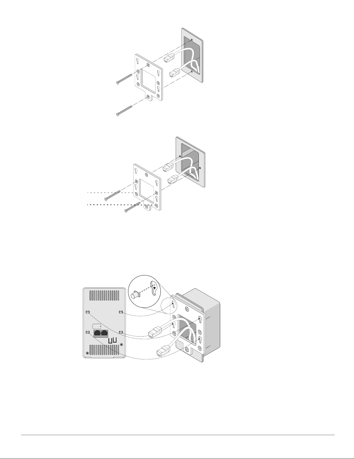
Figure 2 Bracket to Gang Box (US Single Gang Outlet Box Shown))
Figure 3 Bracket to Gang Box (Worldwide Single Gang Outlet Box Shown)
Another
two
mounting
holes
6. Connect any required cables to the back of the AP.
7. Align the mounting posts on the back of the AP with the corresponding mounting holes on the mounting
bracket as shown in Figure 4.
8. Push the AP against the holes and downward until the posts engage the slots at the top of the mounting
holes. See Figure 4 and Figure 5 for more details.
Figure 4 Fitting AP to Bracket
2 AP-103H-MNT1 Mounting Kit | Installation Guide
 Loading...