


Dell Networking
W-7024 Controller
Installation Guide

Copyright Information
© 2015 Aruba Networks, Inc. Aruba Networks trademarks include , Aruba Networks®, Aruba
Wireless Networks®, the registered Aruba the Mobile Edge Company logo, and Aruba Mobility Management
System®. Dell™, the DELL™ logo, and PowerConnect™ are trademarks of Dell Inc.
All rights reserved. Specifications in this manual are subject to change without notice.
Originated in the USA. All other trademarks are the property of their respective owners.
Open Source Code
Certain Aruba products include Open Source software code developed by third parties, including software code
subject to the GNU General Public License (GPL), GNU Lesser General Public License (LGPL), or other Open
Source Licenses. Includes software from Litech Systems Design. The IF-MAP client library copyright 2011 Infoblox,
Inc. All rights reserved. This product includes software developed by Lars Fenneberg, et al. The Open Source code
used can be found at this site:
http://www.arubanetworks.com/open_source
Legal Notice
The use of Aruba Networks, Inc. switching platforms and software, by all individuals or corporations, to terminate
other vendors’ VPN client devices constitutes complete acceptance of liability by that individual or corporation for
this action and indemnifies, in full, Aruba Networks, Inc. from any and all legal actions that might be taken against it
with respect to infringement of copyright on behalf of those vendors.
0511712-01 | April 2015 2

Contents
Contents
Preface
Guide Overview
Related Documentation
Contacting Dell
W-7024 Controller
Packaging Checklist
W-7024 Components
Access Ports
Access Port LEDs
Uplink Ports
Uplink Port LEDs
SFP/SFP+ Modules and DAC Cables
Management Port
3
7
7
7
7
8
8
9
10
10
11
11
12
13
Power, Status, and Peered LEDs
LCD Panel
LCD Mode Menu
Disabling the LCD Screen
USB Interface
Serial Console Port
Serial Console Port Adaptor
Micro-USB Console Port
Micro-USB Driver
Power Supply
Grounding Point
Installation
13
14
14
15
16
16
16
17
17
17
17
18
Dell Networking W-7024 Controller | Installation Guide Contents | 3

Precautions
18
Selecting a Location
Rack Mounting - Standard/Front
Required Tools and Equipment
Installation Steps
Rack Mount Installation- Mid
Required Tools and Equipment
Installation Steps
Table or Shelf Installation
Required Tools and Equipment
Installation Steps
Wall Mounting
Required Tools and Equipment
Installation Steps
Connecting and Disconnecting the AC Power Cord
19
19
19
20
20
21
21
22
22
22
22
23
23
24
Connecting the AC Power Cord
Disconnecting the AC Power Cord
Installing an SFP/SFP+ Module
Removing an SFP/SFP+ Module
Connecting an LC Fiber Optic Cable
Disconnecting an LC Fiber Optic Cable
Specifications, Safety, and Compliance
W-7024 Specifications
Physical
Power Supply Specifications
Operating Specifications
Storage Specifications
Safety and Regulatory Compliance
Regulatory Model Name
24
25
25
25
25
26
27
27
27
27
27
27
27
28
Electromagnetic Interference
United States
FCC Class A
4 | Contents Dell Networking W-7024 Controller | Installation Guide
28
28
28

Canada
29
Japan VCCI
Taiwan (BSMI)
Europe
South Korea
EU Regulatory Conformance
Battery Statements
Proper Disposal of Dell Equipment
Waste of Electrical and Electronic Equipment
European Union RoHS
India RoHS
China RoHS
29
29
29
29
30
30
30
30
30
30
31
Dell Networking W-7024 Controller | Installation Guide Contents | 5

Preface
This document describes the hardware features of the Dell Networking W-7024 Controller. It provides a detailed
overview of the physical and performance characteristics of the controller and explains how to install the controller
and its accessories.
Guide Overview
l W-7024 Controller on page 8 provides a detailed hardware overview of the W-7024 controller and its
components.
l Installation on page 18 describes how to install the W-7024 controller and its components.
l Specifications, Safety, and Compliance on page 27 provides the W-7024 controller’s technical specifications and
safety and regulatory compliance information.
Related Documentation
Refer to the latest
Reference Guide
Dell Networking W-Series ArubaOS User Guide
for complete management of the controller.
Contacting Dell
Table 1: Contact Information
Web Site Support
Main Website dell.com
Contact Information dell.com/contactdell
Support Website dell.com/support
Documentation Website dell.com/support/manuals
and
Dell Networking W-Series ArubaOS CLI
Dell Networking W-7024 Controller | Installation Guide Preface | 7
Chapter 1
W-7024 Controller
The W-7024 Controller is a wireless LAN controller that connects, controls, and intelligently integrates wireless
Access Points (APs) and Air Monitors (AMs) into a wired LAN system.
There are two models of the W-7024 controller that do not differ physically or functionally from each other.
l W-7024-US: For the United States of America
l W-7024-RW: For the rest of the world
The W-7024 controller has the following port configuration:
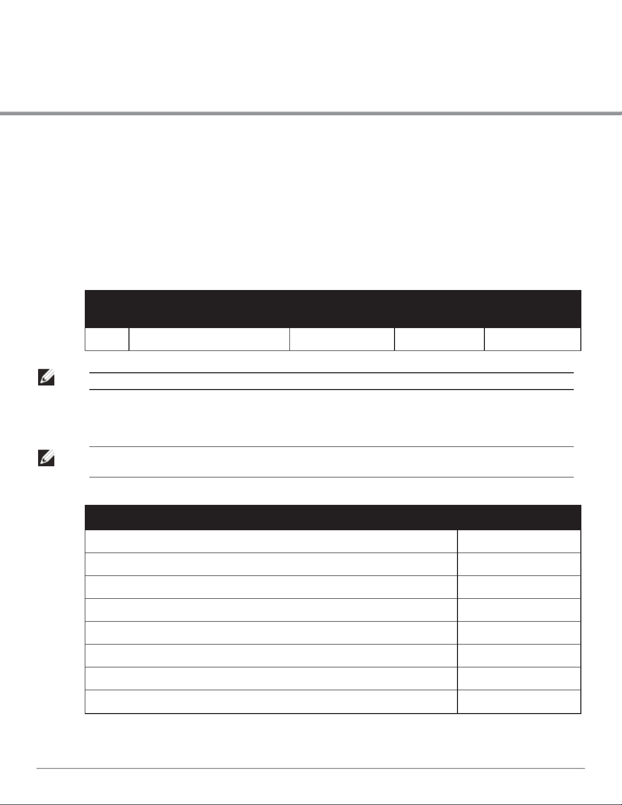
Table 2: W-7024 Controller Port Configuration
Model Access Ports Uplink Ports
W-7024 24 x 10/100/1000BASE-T PoE/PoE+ 2 x 10GBASE-X 32 2048
NOTE: The W-7024 controller requires Dell Networking W-Series ArubaOS 6.4.3.1 or later version.
Number of APs
Supported
Number of Users
Supported
Packaging Checklist
NOTE: Inform your supplier if there are any incorrect, missing, or damaged parts. If possible, retain the carton, including the
original packing materials (see Table 3). Use these materials to repack and return the unit to the supplier if needed.
Table 3: Package Contents
Item Quantity
W-7024 Controller 1
Standard Mounting Brackets 2
M6 x 15 mm Phillips Pan Head Screws 4
M4 x 8 mm Phillips Flat Head Screws
M6 x 7 mm Grounding Screws 2
M6 Cage Nut 4
M6 Clip Nut 4
AC Power Cord Retaining Clip 1
Dell Networking W-7024 Controller | Installation Guide W-7024 Controller | 8
8
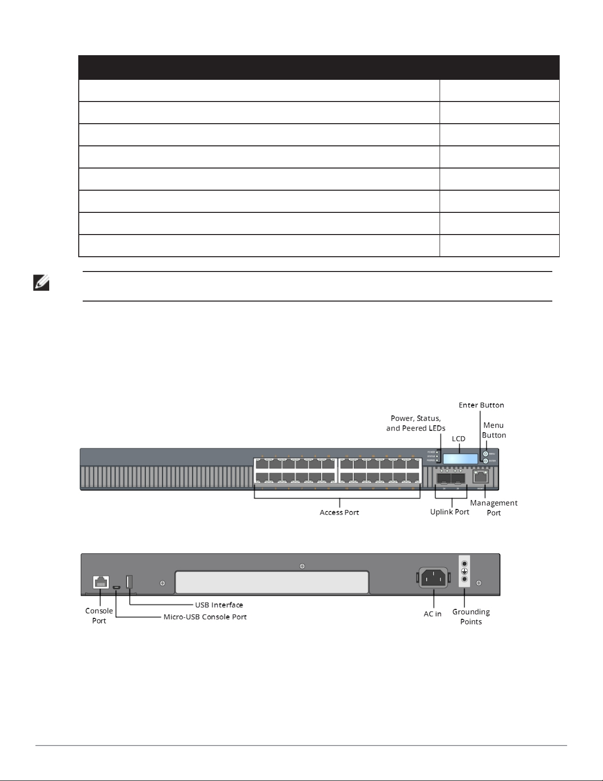
Table 3: Package Contents
Item Quantity
Power Cable 1
Micro-USB Cable 1
Rubber Feet 4
Installation Guide (this document, printed) 1
Quick Start Guide (printed) 1
Dell Safety, Environment, and Regulatory Information (printed) 1
Dell Warranty and S uppor t Information (printed) 1
Dell Software License Agreement (printed) 1
NOTE: Optional accessories are available for use with the W-7024 controller and are sold separately. Contact your Dell sales
representative for details and assistance.
W-7024 Components
This section introduces the component and its location in the W-7024 controller. Figure 1 shows the front panel of
the W-7024 controller and Figure 2 shows the back panel of the W-7024 controller.
Figure 1: Front Panel of the W-7024 Controller.
Figure 2: Back Panel of the W-7024 Controller
9 | W-7024 Controller Dell Networking W-7024 Controller | Installation Guide
The following table lists the different components of the W-7024 controller:
Table 4: W-7024 Controller Components
Component Description Page
Access ports 24 x 10/100/1000BASE-T PoE/PoE+ Ethernet ports
Uplink ports 2 x 10GBASE-X ports
Management port Allows connection to a separate management network
Power, Status, and Peered LED Provides basic monitoring of the controller
LCD Allows configuration of LCD behavior and other basic operations
Enter button Allows execution of actions on the LCD Screen
Menu button Allows selection of the LCD screen menu
USB interface Allows uploading configuration and image from a USB 2.0 storage device.
Serial Console port RJ-45 serial console access port for direct local management
Micro-USB console port Micro-USB console access port for direct local management
AC in AC power connector
Grounding points Provided for attaching the grounding
Access Ports
10
11
13
13
14
16
16
17
17
17
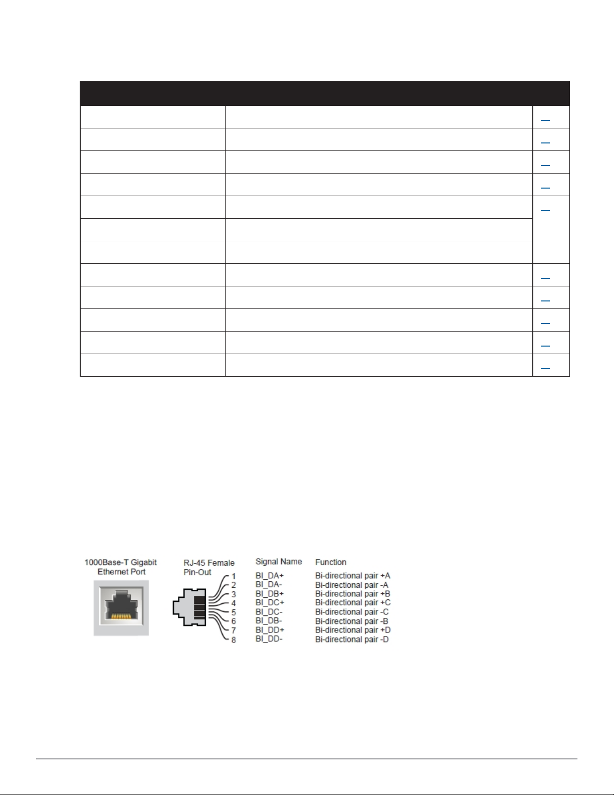
The W-7024 controller is equipped with twenty-four 10/100/1000BASE-T Gigabit Ethernet (RJ-45) ports. These
port are labeled from 0 to 23. Gigabit Ethernet uses all eight wires and each pair is bi-directional, which means, the
same pair is used for both data transmission and data reception. Figure 3 illustrates the Gigabit Ethernet port pin-
out for an RJ-45 connector. The pins paired on a 10/100/1000BASE-T Gigabit Ethernet port are: 1/2, 3/6, 4/5, and
7/8.
All Power over Ethernet (PoE) capable ports support IEEE 802.3af PoE, providing up to 15.4 W of DC power, and
IEEE 802.3at Power over Ethernet Plus (PoE+), supplying up to 30.0 W of DC power to connected devices, but
the power per port is subject to the total PoE power available in the chassis.
Figure 3: 10/100/1000BASE-T Port Pin Out
Access Port LEDs
Each 10/100/1000BASE-T Gigabit Ethernet port is equipped two LEDs that allow basic monitoring of status,
activity, and configuration of the port.
Dell Networking W-7024 Controller | Installation Guide W-7024 Controller | 10
 Loading...