

Dell W-650 Installation Manual

Dell PowerConnect
W-650 Controller
Installation Guide

Copyright
© 2010 Aruba Networks, Inc. AirWave®, Aruba Networks®, Aruba Mobility Management System®, and other registered marks are
trademarks of Aruba Networks, Inc. Dell™, the DELL™ logo, and PowerConnect™ are trademarks of Dell Inc.
All rights reserved. Specifications in this manual are subject to change without notice.
Originated in the USA. Any other trademarks appearing in this manual are the property of their respective companies.
Open Source Code
Certain Aruba products include Open Source software code developed by third parties, including software code subject to the GNU
General Public License (GPL), GNU Lesser General Public License (LGPL), or other Open Source Licenses. The Open Source code
used can be found at this site:
http://www.arubanetworks.com/open_source
Legal Notice
The use of Aruba Networks, Inc. switching platforms and software, by all individuals or corporations, to terminate other vendors' VPN
client devices constitutes complete acceptance of liability by that individual or corporation for this action and indemnifies, in full, Aruba
Networks, Inc. from any and all legal actions that might be taken against it with respect to infringement of copyright on behalf of those
vendors.
Dell PowerConnect W-650 Controller | Installation Guide 0510573-MU-01 | July 2010

Contents
Preface........................................................................................................................................................................5
General Overview...............................................................................................................................5
Related Documentation.....................................................................................................................5
Contacting Dell ................................................................................................................................... 5
Chapter 1 About the W-650 Series Controller....................................................................................7
Minimum Software Requirements...................................................................................................7
Package Checklist..............................................................................................................................7
Hardware Model Overview............................................................................................................... 8
Front View.................................................................................................................................... 8
1000Base-X (SFP) Ports..................................................................................................... 8
10/100/1000Base-T Gigabit Ethernet Ports.....................................................................8
Serial Console Port ............................................................................................................8
Serial Console Port Adaptor............................................................................................. 9
USB Ports ............................................................................................................................9
Media Eject Button ..........................................................................................................10
Rear View...................................................................................................................................10
AC Power Socket .............................................................................................................10
ExpressCard Slot ..............................................................................................................11
Antennae Interfaces (W-651 Only)................................................................................ 11
LED Status Indicators ......................................................................................................................11
Chapter 2 W-650 Series Installation..................................................................................................13
Pre-Installation Requirements .......................................................................................................13
For a Telecom Rack:.................................................................................................................13
For a Server Rack:.................................................................................................................... 13
Installation in a Telecom Rack .......................................................................................................13
Installation in a Server Rack........................................................................................................... 15
Tabletop Deployment....................................................................................................................... 16
Initial Setup and Network Connectivity ........................................................................................16
Removal.............................................................................................................................................. 16
Appendix A Specifications, Safety, and Compliance.........................................................................17
Physical Specifications ...................................................................................................................17
Power Specifications....................................................................................................................... 17
Operating Specifications................................................................................................................. 17
Storage Specifications ....................................................................................................................17
Wireless Radio Specifications (W-651 Internal AP)................................................................... 17
AP type....................................................................................................................................... 17
Operating Frequency ...............................................................................................................17
Available Channels...................................................................................................................17
Modulations...............................................................................................................................17
Transmit Power.........................................................................................................................18
Association Rates (Mbps)....................................................................................................... 18
802.11n High-Throughput (HT) Support ................................................................................18
802.11n Packet Aggregation................................................................................................... 18
Dell PowerConnect W-650 Controller | Installation Guide Contents | 3

Antenna (W-651 Internal AP) .................................................................................................18
Safety and Regulatory Compliance ...............................................................................................18
FCC Class B Device.................................................................................................................. 18
RF Radiation Exposure Statement .........................................................................................19
W-650..........................................................................................................................................19
W-651..........................................................................................................................................19
NOM Information (Mexico Only)............................................................................................20
Proper Disposal of Dell Equipment................................................................................................ 20
European Union RoHS .............................................................................................................20
4 |Contents Dell PowerConnect W-650 Controller | Installation Guide

Preface
This preface includes the following information:
z An overview of the contents of this manual
z A list of related documentation for further reading
z Support and service information
General Overview
z Chapter 1, “About the W-650 Series Controller” on page 7 provides a detailed hardware overview of the
W-650 Series.
z Chapter 2, “W-650 Series Installation” on page 13 provides rack mounting and installation instructions.
z Appendix A, “Specifications, Safety, and Compliance” on page17 includes product technical
specifications, safety, and regulatory compliance information.
Related Documentation
The following documentation are referred to in this guide and are considered components of the complete
documentation set needed for a successful installation and management of a Dell Mobility Controller.
z
Dell PowerConnect ArubaOS 5.0 Quick Start Guide
z
Dell PowerConnect ArubaOS 5.0 User Guide
z
Dell PowerConnect ArubaOS 5.0 Command Line Reference
Contacting Dell
Web Site Support
Main Site www.dell.com
Support Site support.dell.com
Documentation support.dell.com/manuals
Software https://download.dell-pcw.com
Dell PowerConnect W-650 Controller | Installation Guide Preface | 5

6 | Preface Dell PowerConnect W-650 Controller | Installation Guide

Chapter 1
About the W-650 Series Controller
The Dell PowerConnect W-650 Series controller is an enterprise-class, wireless LAN controller. This controller
connects, controls, and integrates wireless Access Points (APs) and Air Montitors (AMs) into a wired LAN system.
z The W-650 is capable of supporting up to 16 external, campus APs.
z The W-651 is capable of supporting up to 16 external, campus APs in addition to its single, internal AP.
Minimum Software Requirements
The W-650 Series controller requires ArubaOS 5.0.2 or later.
Note: The master controller, its redundant master controller, and all of its local controllers must run on the same code of ArubaOS.
Once you upgrade your network and install a W-650 Series Mobility Controller into your network, verify that the software version
on your controller matches the rest of your network.
Package Checklist
z W-650 Series Mobility Controller
z AC Power Cord (country-specific)
z Rack Mount Brackets
z Rack Mounting Hardware for Server and Telecom Rack Systems
z Left Side Bezel (not installed)
z Right Side Bezel (not installed)
z Rubber Feet (for table top deployments)
z Flat Serial Cable (RJ-45)
z Serial Cable Port Adapter (RJ-45 to DB9)
z Dual-band, High-gain, Omni-directional Detachable Antennae (3x)
z
Dell PowerConnect ArubaOS Quick Start Guide
z End User License Agreement (EULA)
z Safety, Environmental, and Regulatory Information (SERI) document
z Warranty and Support Information (WSI) document
Note: Inform your supplier if there are any incorrect, missing, or damaged parts. If possible, retain the carton, including the original
packing materials. Use these materials to repack and return the unit to the supplier if needed.
Dell PowerConnect W-650 Controller | Installation Guide About the W-650 Series Controller | 7
Hardware Model Overview
10/100/1000Base-T Gigabit
Ethernet Ports with PoE
1000Base-X (SFP) Ports
USB ports
10/100/1000Base-T Gigabit Ethernet Ports
Media Eject Button
Serial Console Port
WLAN LED
1000Base-T Gigabit
Ethernet Port
RJ-45 Female
Pin-Out
Signal Name
1
2
3
4
5
6
7
8
BI_DC+
BI_DC-
BI_DD+
BI_DD-
BI_DA+
BI_DABI_DB+
BI_DB-
Function
Bi-directional pair +C
Bi-directional pair -C
Bi-directional pair +D
Bi-directional pair -D
Bi-directional pair +A
Bi-directional pair -A
Bi-directional pair +B
Bi-directional pair -B
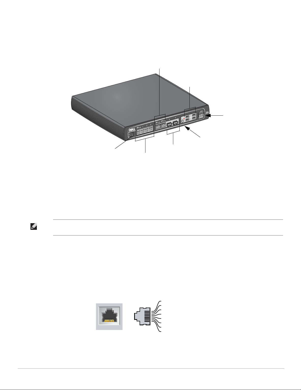
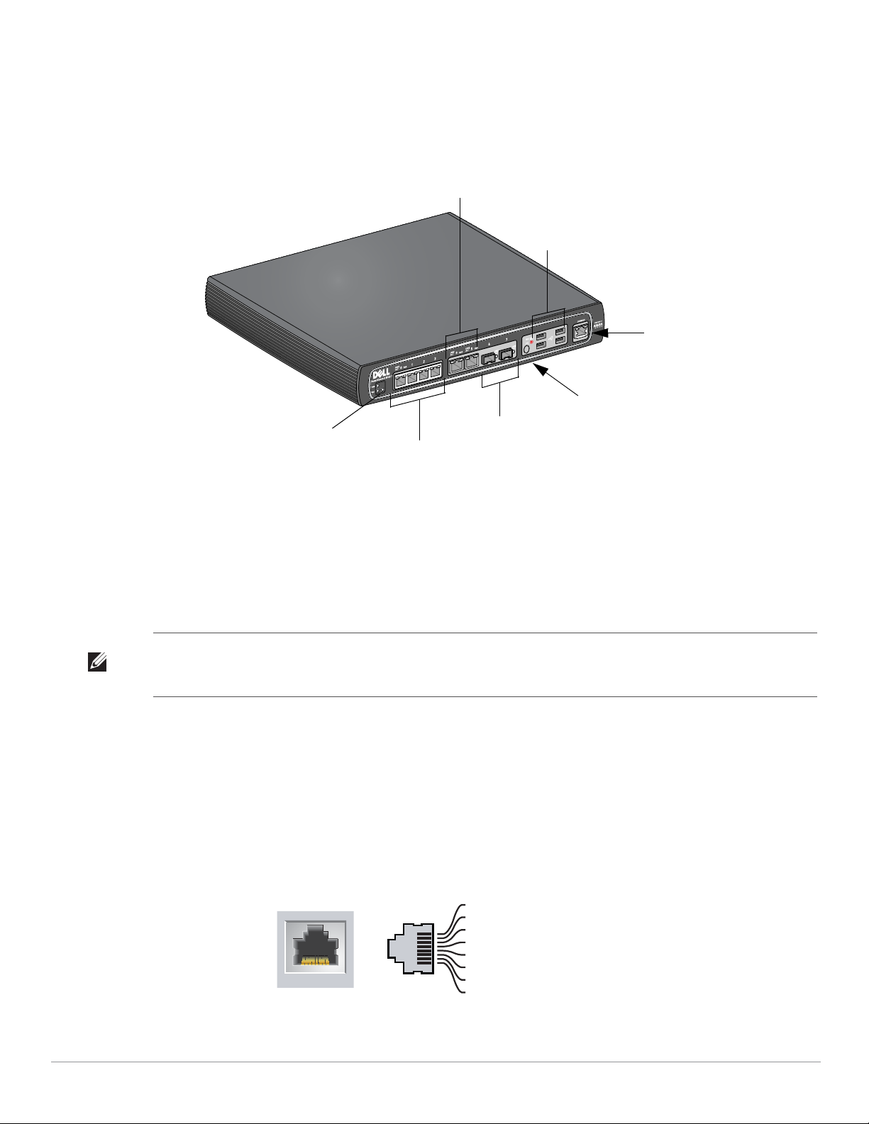
Front View
Figure 1 W-650 Series Front View
1000Base-X (SFP) Ports
There are two 1000Base-X ports for fiber connectivity only and are intended for use with Dell W-Series SFPs
(mini-GBICs).
To purchase compatible SFP modules, contact your Dell sales representative for details and assistance.
Note: Dell tests and supports Dell optics within their controller system. Third party optics are not tested or supported; therefore,
Dell does not guarantee proper functionality of third party optics when used in a Dell system.
10/100/1000Base-T Gigabit Ethernet Ports
There are six 10/100/1000Base-T Gigabit Ethernet (RJ-45) ports on the W-650 Series. Gigabit Ethernet uses all
eight wires and each pair is used in a bi-directional fashion, meaning the same pairs are used for both data
transmission and reception. Figure 2 illustrates the CAT-5 pin-out found on an RJ-45 connector. The CAT-5 pinout pairs the following pins on a 10/100/1000Base-T Gigabit Ethernet port: 1/2, 3/6, 4/5, and 7/8.
Figure 2 Gigabit Ethernet Port Pin-Out
8 | About the W-650 Series Controller Dell PowerConnect W-650 Controller | Installation Guide
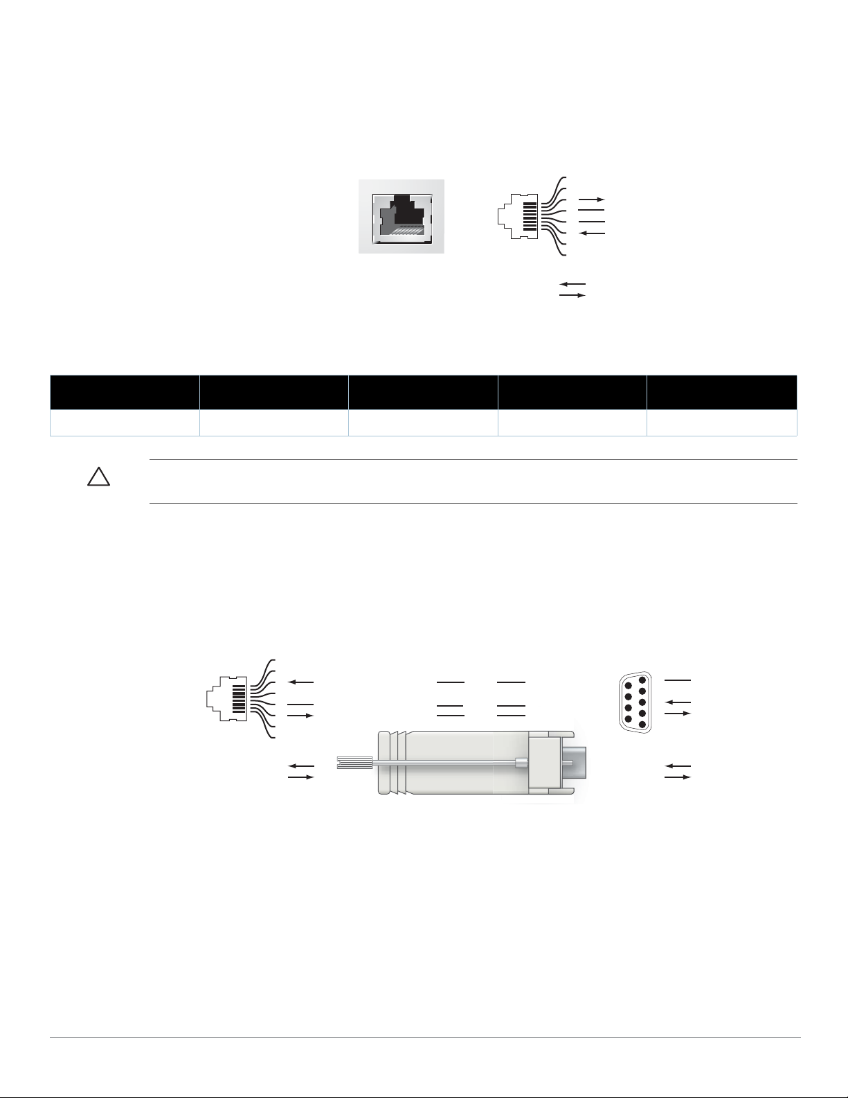
Serial Console Port
A serial console port is provided for connection to a terminal, allowing for direct local management.
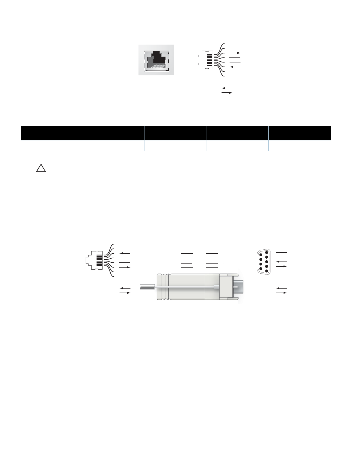
Figure 3 Serial Console Port Pin-Out
Serial
Console Port
1
2
3
4
5
6
7
8
TxD
GND
RxD
RJ-45 Female
Pin-Out
Direction
Input
Output
GND
3
4
5
2
5
63
RJ-45 DB-9
Internal
Connections
TxD
GND
RxD
1
2
3
4
5
6
7
8
TxD
GND
RxD
RJ-45 Female
Pin-Out
Direction
Input
Output
DB-9 Male
Pin-Out
TxD
RxD
Ground
5
4
3
2
1
9
8
7
6
Direction
Input
Output
Communication settings for the serial port are indicated in Table 1.
Table 1 Console Terminal Settings
Baud Rate Data Bits Parity Stop Bits Flow Control
9600 8 None 1 None
Caution: Do not connect an AP to the serial console port. The serial console port is compatible only with RS-232 devices. NonRS-232 devices, such as APs, are not supported.
Serial Console Port Adaptor
A modular adaptor can be used to convert the RJ-45 (female) connector to a DB9 (male) connector. Refer to
Figure 4 for complete details.
Figure 4 RJ-45 (female) to DB9 (male) Modular Adaptor Conversion
USB Ports
The W-650 Series has four USB 2.0 interfaces. These interfaces allow the use of EVDO/HSPDA modem, flash or
disk storage devices, or a printer. For more information about configuring and using USB devices with the W-650
Series, see the ArubaOS User Guide.
Dell PowerConnect W-650 Controller | Installation Guide About the W-650 Series Controller | 9
Media Eject Button
AC Power Socket
ExpressCard Slot
Antennae Interfaces
(651 Only)
The W-650 Series is equipped with a media eject button, which allows users to eject storage devices safely and
place the system in standby. When the button is pushed, the all storage media devices attached to the controller
via USB is unmounted. Printers and EVDO devices are unaffected.
Pushing the media eject button changes the state of the W-650 Series; the table below describes the states and
LED behaviors associated with use of the media eject button.
Table 2 Media Eject Button LED Behavior
Initial State LED State Action Status LED Function
NAS Media Operational Green-solid Press and hold media
eject button for 1 to 5
seconds only
NAS Media Unmounted Amber-solid Press and hold media
eject button for 1 to 5
seconds only
Operational Green-solid Press and hold media
eject button for more
than 5 seconds only
Operating with NAS Media
un-mounted
Standby Red-solid Press media eject
Amber-solid Press and hold media
eject button for more
than 5 seconds only
button
Amber-flashing Un-mount all NAS
Amber-flashing Mount all attached
Red-flashing Controller goes into
Red-flashing Controller goes into
Amber-flashing Controller wake-up Green-solid
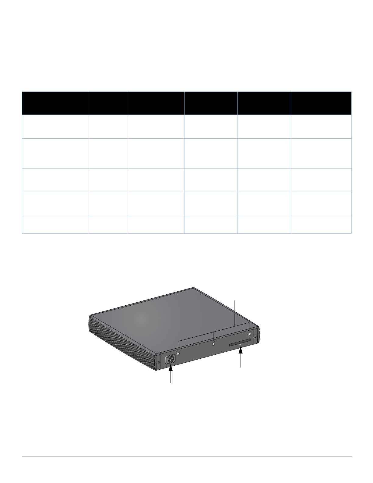
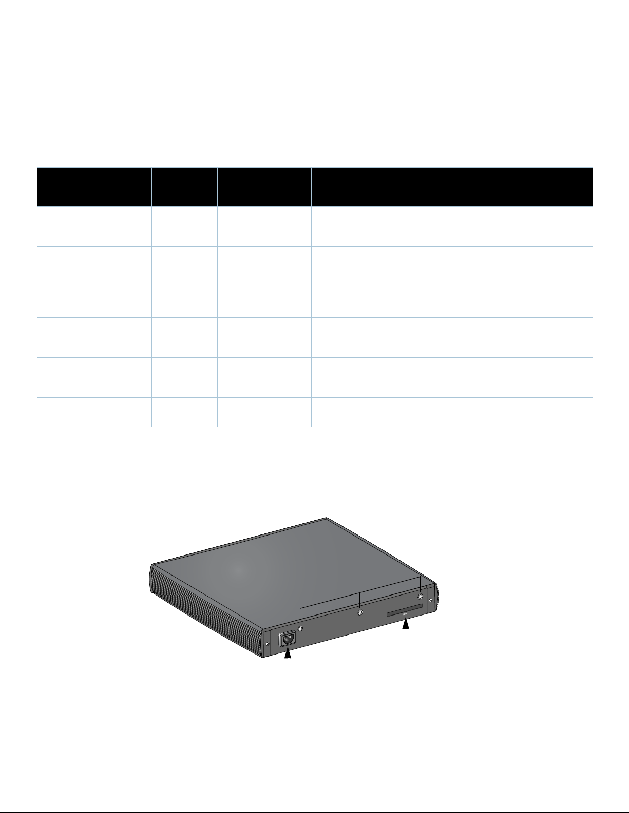
Rear View
Figure 5 W-650 Series Rear View (651 Shown)
LED Action
Completed
Amber-solid
media
Green-solid
NAS device, and
return to fully
functional operation
Red-solid
Standby
Red-solid
Standby
AC Power Socket
The W-650 Series supports integrated AC powering and the AC power socket on the rear of the unit is for use
with an AC power cord (country-specific). Refer to “Power Specifications” on page17 for power specification
details.
10 | About the W-650 Series Controller Dell PowerConnect W-650 Controller | Installation Guide

ExpressCard Slot
The W-650 Series is equipped with one ExpressCard slot, which can be used with an EVDO device.
Antennae Interfaces (W-651 Only)
The W-651 is equipped with an internal Access Point (AP). This AP can operate in 2.4 GHz and 5 GHz bands, in
a/b/g or n modes. Each appliance has three RP-SMA interfaces to attach the antennas included in this kit.
LED Status Indicators
Table 3 W-650 Series LED Status Indicators
LED Label Function Indicator Status
Power POWER Input Power Status Indicator On (Solid Green) Power on
Off No Power
Status STATUS Module Status Indicator On (Solid Green) Device is operational
On (Solid Red) Device failed or is in Standby
On (Solid Amber) Device is loading software
Off No power
1000Base-X Ports (SFP) LNK/ACT Link Status Indicator On (Solid Green) Link has been established
On (Flashing Green) Port is transmitting or receiving
data
Off No link on port
10/100/1000Base-T Ports LNK/ACT Link/Activity Status Indicator On (Solid Green) Link has been established
10/100/1000Base-T Ports
with PoE
On (Flashing Green) Port is transmitting or receiving
Off No link on port
1000 Interface Speed On (Solid Green) 1000 Mbps
Off 10/100 Mbps
LINK/ACT Link/Activity Status Indicator On (Solid Green) Link has been established
On (Flashing Green) Port is transmitting or receiving
Off No link on port
PoE PoE Status Indicator On (Solid Green) PoE is being provided
On (Solid Amber) The attached device has
data
data
requested PoE, but PoE is not
being provided by the port
Off PoE is not being provided
802.11 a/b/g/n AP
(W-651 Only)
Dell PowerConnect W-650 Controller | Installation Guide About the W-650 Series Controller | 11
WLAN AP Status On (Solid Amber) Radio enabled in WLAN mode
On (Solid Green) Radio enabled in 802.11n mode
On (Flashing Green) Air monitor mode
Off Radio is disabled

12 | About the W-650 Series Controller Dell PowerConnect W-650 Controller | Installation Guide

Chapter 2
W-650 Series Installation
Pre-Installation Requirements
The following tools and equipment are required for installation of a W-650 Series controller.
z Rack Mount Bracket (x2, not used for tabletop installation)
z Suitable Screwdrivers
z AC Power Cord (country-specific)
z Left and right side bezels (not used for rack mounting)
Warning: Before performing the following procedure, review the safety instructions that came with the controller.
For a Telecom Rack:
z M3, 6mm x 0.5mm Phillips Head Screws (6x, included)
z 12-24 x 5/8” Phillips Head Screws (4x, included)
For a Server Rack:
z M3, 6mm x 0.5mm Phillips Head Screws (6x, included)
z M6 x 20mm Phillips Head Screws (4x, included)
z M6 Cage Nuts (4x, included) or M6 Cage Clips (4x, included)
Installation in a Telecom Rack
To install a W-650 Series controller into a 19-inch (48.26 cm) Telecom rack system:
1. Place a rack mount bracket over the mounting holes on one side of the controller (see Figure 6).
2. Secure the bracket to the controller using three M3, 6mm x 0.5mm phillips head screws and a screwdriver.
3. Repeat these steps on the opposite side of the controller.
Dell PowerConnect W-650 Controller | Installation Guide W-650 Series Installation | 13
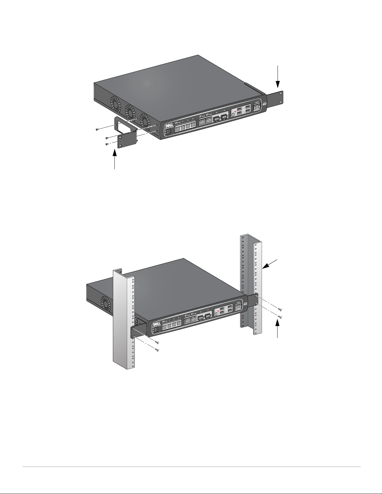
Figure 6 Rack Mount Brackets
6-32 x 1/4” Phillips Flat Head Screws
(6x, 2x per bracket)
Rack Mount Bracket (2x)
12-24 x 5/8”
Phillips Flat Head Screws
(4x, 2x per bracket)
Standard 19-inch
Rack System
4. Mount the controller within your organization’s rack system using four 12-24 x 5/8” phillips head screws and
suitable screwdriver (see Figure 7).
Figure 7 Rack Mount Installation
5. Leave a minimum of four inches (10cm) of space on the left and right side of the unit for proper air flow and
ventilation (see Figure 8).
6. Leave additional space in front and back of the unit to access power cords, network cables, and LED status
indicators (see Figure 8).
14 | W-650 Series Installation Dell PowerConnect W-650 Controller | Installation Guide
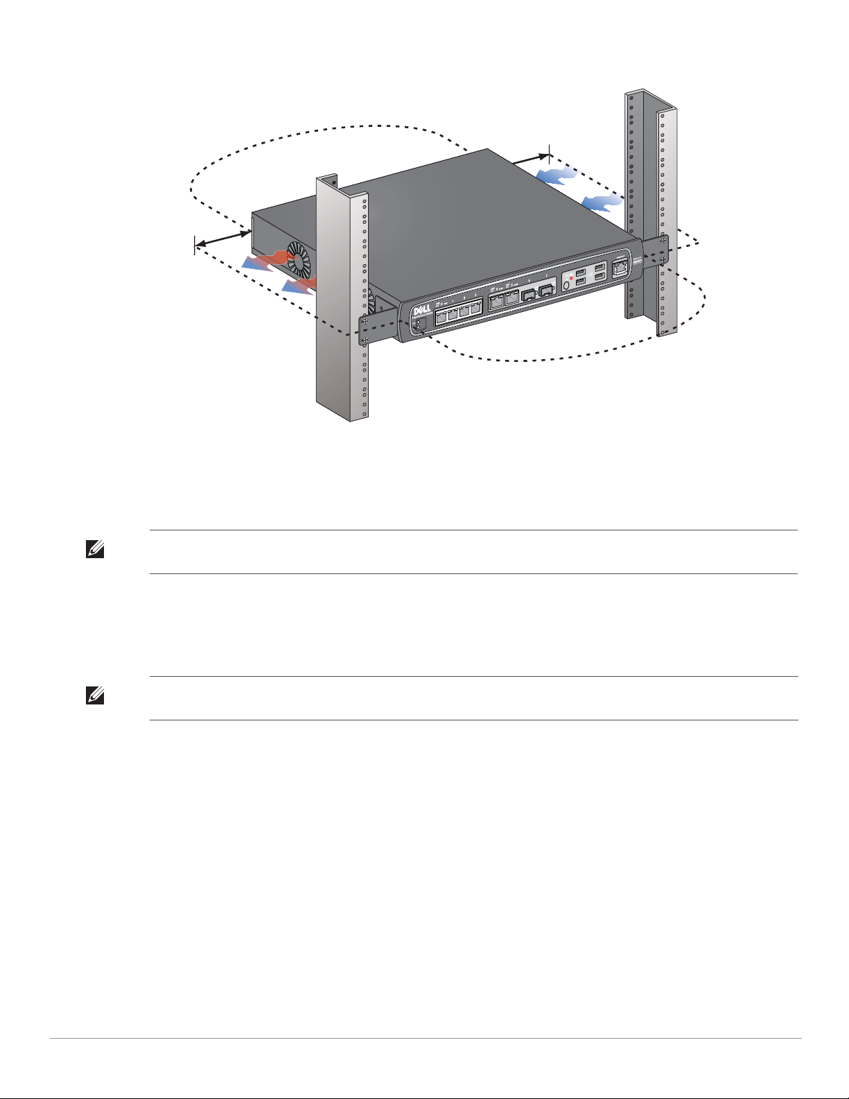
Figure 8 Air Flow Requirements
Keep Open for
Easy Access
Keep Clear for
Air Exhaust
Keep Clear for
Air Intake
Keep Open for
Easy Access
7. Connect the AC power cord (country-specific) to the rear of the unit.
8. Plug the opposite end of the power cord into an electrical outlet to power the controller.
Note: W-650 Series controller does not have a switch for turning power to the unit on or off. Power to the unit is controlled by
connecting or disconnecting the plug on the power cord to or from an electrical outlet.
Installation in a Server Rack
To install a W-650 Series controller into a 19-inch (48.26 cm) Server rack system:
Note: The following instructions describe the installation of your controller in a rack with unthreaded, square holes. For a rack
with unthreaded, round holes, use the provided clip nuts instead.
1. Place a rack mount bracket over the mounting holes on one side of the controller (see Figure 6).
2. Secure the bracket to the controller using three M3, 6mm x 0.5mm phillips head screws and a suitable
3. Repeat these steps on the opposite side of the controller.
4. Install the four cage nuts.
screwdriver.
To install the cage nut with a cage-nut installation tool:
a. Begin by inserting the lower lip of the cage nut over the bottom of the square opening in the back of the
rail.
b. Insert the small end of the cage-nut installation tool through the opening in the rail (from the front), and
hook the tool over the top lip of the cage nut.
c. Push the cage nut in towards the rail while rotating the tool up and pulling the tool back toward you until
the top lip of the cage nut snaps into position.
To install the cage nut with a flathead screwdriver:
Dell PowerConnect W-650 Controller | Installation Guide W-650 Series Installation | 15

a. Begin by inserting the lower lip of the cage nut over the bottom of the square opening in the back of the
rail.
b. Compress the top lip of the cage nut with a flathead screwdriver.
c. With the lip compressed, push the cage nut’s lip fully into the opening in the rail.
d. Release the scredriver pressure on the cage nut to lock it into place.
5. Mount the controller within your organization’s rack system using four M6 x 20mm phillips head screws and
suitable screwdriver.
6. Leave a minimum of four inches (10cm) of space on the left and right side of the unit for proper air flow and
ventilation (see Figure 8).
7. Leave additional space in front and back of the unit to access power cords, network cables, and LED status
indicators (see Figure 8).
8. Connect the AC power cord (country-specific) to the rear of the unit.
9. Plug the opposite end of the power cord into an electrical outlet to power the controller.
Note: W-650 Series controller does not have a switch for turning power to the unit on or off. Power to the unit is controlled by
connecting or disconnecting the plug on the power cord to or from an electrical outlet.
Tabletop Deployment
To deploy a W-650 Series controller on a flat surface, such as a tabletop:
1. Insert the four rubber mounting feet to the bottom of the unit.
2. Attach side bezels by snapping them into place.
3. Place the unit on a hard flat surface.
Initial Setup and Network Connectivity
Once the physical installation is complete, run the initial setup on the controller to configure the IP address and
other basic system information. For complete details and instructions, refer to the ArubaOS Quick Start Guide.
Removal
To remove a W-650 Series controller from a 19-inch (48.26 cm) rack system:
1. Disconnect the power to the controller by unplugging the power cord from the electrical outlet.
2. Disconnect any other cables or devices attached to the controller.
3. Loosen the four rack mount screws securing the controller to your organizations rack system.
4. Remove the controller from the rack system.
16 | W-650 Series Installation Dell PowerConnect W-650 Controller | Installation Guide

Physical Specifications
Device Dimensions (without rack mount brackets)
z Height 1.5˝ (38 mm)
z Width 13.6˝ (346 mm)
z Depth 8.9˝ (226 mm)
Power Specifications
z AC Input Voltage: 100-240 V, Universal Input
z AC Input Frequency: 50-60 Hz
z Maximum power consumption: 126 Watts
z Power over Ethernet total capacity: 78 Watts
z Power over Ethernet capacity per port: 19.5 Watts
Appendix A
Specifications, Safety, and Compliance
Operating Specifications
z Operating Temperature Range: 0°C to 40°C (32°F to 104°F)
z Operating Humidity Range: 5% to 95% (RH), non-condensing
Storage Specifications
z Storage Temperature Range: 0°C to 50°C (32°F to 122°F)
z Storage Humidity Range: 5% to 95% (RH), non-condensing
Wireless Radio Specifications (W-651 Internal AP)
AP type
z Single Radio, 3x3 Multiple-In, Multiple-Out (MIMO) providing data rate up to 300 Mbps
Operating Frequency
z 2.4-2.5 GHz or 5.150–5.950 GHz
Available Channels
z Mobility Controller-managed, dependent upon configured regulatory domain
Modulations
z 802.11b: Direct-Sequence Spread-Spectrum (DSSS)
z 802.11a/g: Orthogonal Frequency Division Multiplexing (OFDM)
z 802.11n: 802.11n draft 2.0
Dell PowerConnect W-650 Controller | Installation Guide Specifications, Safety, and Compliance | 17
Transmit Power
z Configurable in increments of 0.5 dBm
Association Rates (Mbps)
z 802.11b: 11, 5.5, 2, 1 with automatic fallback
z 802.11a/g: 54, 48, 36, 24, 18, 12, 9, 6 with automatic fallback
z 802.11n: MCS0 - MCS15 (6.5Mbps - 300Mbps)
802.11n High-Throughput (HT) Support
z HT 20
z HT 40
802.11n Packet Aggregation
z A-MPDU
z A-MSDU
Antenna (W-651 Internal AP)
z Three RP-SMA interfaces for external antenna support (supports up to 3x3 MIMO with spatial diversity)
z Three AP-ANT-1B omni-directional dual-band antennas included
Safety and Regulatory Compliance
Dell provides a multi-language document containing country specific restrictions and additional safety and
regulatory information for all Dell hardware products. The Dell PowerConnect W-Series Safety, Environmental,
and Regulatory Information document is included with this product.
CLASS 1
LASER PRODUCT
Caution: Use of controls or adjustments of performance or procedures other than those specified in this manual may result in
hazardous radiation exposure.
This product complies with 21 CFR Chapter 1, Subchapter J, Part 1040.10, and IEC 60825-1: 1993, A1: 1997, A2:
2001, IEC 60825-2: 2000.
For continued compliance with the above laser safety standards, only approved Class 1 modules from our
approved vendors should be installed in Dell products.
FCC Class B Device
This equipment has been tested and found to comply with the limits for a Class B digital device, pursuant to part
15 of the FCC Rules. These limits are designed to provide reasonable protection against harmful interference in a
residential installation. This equipment generates, uses and can radiate radio frequency energy and, if not
installed and used in accordance with the instructions, may cause harmful interference to radio communications.
However, there is no guarantee that interference will not occur in a particular installation. If this equipment does
18 | Specifications, Safety, and Compliance Dell PowerConnect W-650 Controller | Installation Guide

cause harmful interference to radio or television reception, which can be determined by turning the equipment
off and on, the user is encouraged to try to correct the interference by one or more of the following measures:
z Reorient or relocate the receiving antenna.
z Increase the separation between the equipment and receiver.
z Connect the equipment into an outlet on a circuit different from that to which the receiver is connected.
z Consult the dealer or an experienced radio/ TV technician for help (we can modify this to advise to seek help
of the professional installer).
For a complete list of Country Specific Regulations please speak with your Dell Representative .
RF Radiation Exposure Statement
This equipment complies with FCC RF radiation exposure limits. This equipment should be installed and
operated with a minimum distance of 13.78 inches (35 cm) between the radiator and your body for 2.4 GHz and
5 GHz operations. This transmitter must not be co-located or operating in conjunction with any other antenna or
transmitter. When operated in the 5.15 to 5.25 GHz frequency range, this device is restricted to indoor use to
reduce the potential for harmful interference with co-channel Mobile Satellite Systems.
W-650
z EN 55022 Class B
z EN 55024
z IEC/EN 60950
z CE Marking
z cTUVus Marked
z CB Scheme Certified
W-651
z FCC 15.247/15.407
z EU R&TTE Directive 1999/5/EC (EN 300 328, EN 301 893, EN 301 489)
z EU LV Directive 2006/95/EC
z IEC/EN 60950
z CE Marking
z cTUVus Marked
z CB Scheme Certified
For a complete list of Country Specific Regulations please speak with your Dell Representative.
Dell PowerConnect W-650 Controller | Installation Guide Specifications, Safety, and Compliance | 19

NOM Information (Mexico Only)
The following information is provided on the device described in this document in compliance with the
requirements of the official Mexican standards (NOM):
Importer: Dell Inc. de Mexico, S.A. de C.V.
Paseo de la Reforma 2620-11° Piso
Col. Lomas Atlas
11950 Mexico, D.F.
Model Number: 650/651
z Supply Voltage: 100-240 V AC
z Frequency: 47-63 Hz
z Current consumption: 2.0 A
Proper Disposal of Dell Equipment
For the most current information on Global Environmental Compliance and Dell products please refer to
the Dell PowerConnect W-Series Safety, Environmental, and Regulatory Information document is included
with this product or see our website at www.dell.com.
European Union RoHS
Dell products also comply with the EU Restriction of Hazardous Substances
Directive 2002/95/EC (RoHS). EU RoHS restricts the use of specific hazardous
materials in the manufacture of electrical and electronic equipment. Specifically,
restricted materials under the RoHS Directive are Lead (including Solder used in printed circuit assemblies),
Cadmium, Mercury, Hexavalent Chromium, and Bromine. Some Dell products are subject to the
exemptions listed in RoHS Directive Annex 7 (Lead in solder used in printed circuit assemblies). Products
and packaging will be marked with the “RoHS” label shown at the left indicating conformance to this
Directive.
July 2010 | 0510573-MU-01 Dell PowerConnect W-650 Controller | Installation Guide

Dell PowerConnect
W-650 Controller
Installationsanleitung

Copyright
© 2010 Aruba Networks, Inc. AirWave®, Aruba Networks®, Aruba Mobility Management System®, und andere eingetragene Marken
sind Marken von Aruba Networks, Inc. Dell™, das DELL™-Logo und PowerConnect™ sind Marken von Dell Inc.
Alle Rechte vorbehalten. Spezifikationen in diesem Handbuch können ohne Ankündigung geändert werden.
Hergestellt in den USA. Alle anderen Marken, die in diesem Handbuch erwähnt werden, sind das Eigentum der jeweiligen
Unternehmen.
Open Source Code
Bestimmte Aruba-Produkte enthalten Open Source-Softwarecode, der von Drittanbietern entwickelt wurde, darunter Softwarecode
gemäß GNU General Public License (GPL), GNU Lesser General Public License (LGPL) oder anderen Open Source-Lizenzen.
Den Open Source Code finden Sie auf dieser Website:
http://www.arubanetworks.com/open_source
Rechtliche Hinweise
Die Verwendung von Switching-Plattformen und Software von Aruba Networks, Inc. durch Einzelpersonen oder Unternehmen zur
Terminierung von VPN-Client-Geräten anderer Hersteller stellt die vollständige Anerkennung der Haftbarkeit dieser Einzelpersonen oder
dieses Unternehmens für diese Aktion dar und enthebt Aruba Networks, Inc. zur Gänze aller rechtlichen Maßnahmen, die bezüglich der
Verletzung des Urheberrechts im Namen dieser Hersteller ergriffen werden.
Dell PowerConnect W-650 Controller | Installationsanleitung 0510573-MU-01 | Juli 2010

Inhalt
Vorwort.......................................................................................................................................................................5
Allgemeine Übersicht ........................................................................................................................5
Verwandte Dokumentation ...............................................................................................................5
Kontaktaufnahme mit Dell ................................................................................................................ 5
Kapitel 1 Der W-650 Serie Controller................................................................................................7
Mindestvoraussetzungen für die Software.................................................................................... 7
Checkliste ............................................................................................................................................7
Hardwaremodellübersicht ................................................................................................................8
Vorderansicht..............................................................................................................................8
1000Base-X (SFP)-Ports....................................................................................................8
10/100/1000Base-T-Gigabit-Ethernet-Ports ...................................................................8
Serielle Konsolenschnittstelle .........................................................................................9
Adapter für die serielle Konsolenschnittstelle.............................................................. 9
USB-Anschlüsse ................................................................................................................9
Auswurftaste für Medien................................................................................................10
Rückansicht............................................................................................................................... 10
Netzstromanschluss ........................................................................................................11
ExpressCard-Steckplatz..................................................................................................11
Antennenschnittstellen (nur W-651) .............................................................................11
LED-Statusanzeigen.........................................................................................................................11
Kapitel 2 W-650 Serie - Installation ................................................................................................13
Anforderungen vor der Installation ...............................................................................................13
Bei Verwendung eines Telecom-Racks: ..............................................................................13
Bei Verwendung eines Server-Racks:..................................................................................13
Installation in einem Telecom-Rack..............................................................................................13
Installation in einem Server-Rack .................................................................................................15
Aufstellung......................................................................................................................................... 16
Erstmalige Einrichtung und Netzwerkkonnektivität.................................................................... 16
Ausbau ...............................................................................................................................................16
Anhang A Spezifikationen, Sicherheit und Konformität ...............................................................17
Physische Spezifikationen ..............................................................................................................17
Energiespezifikationen ....................................................................................................................17
Betriebsspezifikationen...................................................................................................................17
Lagerungsspezifikationen ...............................................................................................................17
Wireless-Funkspezifikationen (W-651 Interner AP) ...................................................................17
AP-Typ........................................................................................................................................ 17
Betriebsfrequenz...................................................................................................................... 17
Verfügbare Kanäle ...................................................................................................................17
Modulation.................................................................................................................................17
Übertragungsleistung.............................................................................................................. 18
Übertragungsraten (Mbit/s)....................................................................................................18
802.11n Unterstützung von High-Throughput (HT)..............................................................18
802.11n Paketaggregation....................................................................................................... 18
Dell PowerConnect W-650 Controller | Installationsanleitung Inhalt | 3

Antenne (W-651 Interner AP)................................................................................................. 18
Sicherheits- und Zulassungsbestimmungen ...............................................................................18
FCC Class B-Gerät.................................................................................................................... 19
Erklärung zur Abgabe von Funkstrahlung ............................................................................19
W-650..........................................................................................................................................19
W-651..........................................................................................................................................19
NOM-Informationen (nur Mexiko)......................................................................................... 20
Ordnungsgemäße Entsorgung von Dell-Geräten........................................................................ 20
RoHS-Richtlinie der Europäischen Union ............................................................................20
4 | Inhalt Dell PowerConnect W-650 Controller | Installationsanleitung

Vorwort
Dieses Vorwort enthält die folgenden Informationen:
z Überblick über den Inhalt des vorliegenden Handbuchs
z Liste verwandter Dokumentationen
z Hinweise zu Support und Service
Allgemeine Übersicht
z Kapitel 1, „Der W-650 Serie Controller“ auf Seite 7 enthält einen ausführlichen Überblick über die
Hardware des W-650 Serie
z Kapitel 2, „W-650 Serie - Installation“ auf Seite 13 bietet Informationen zur Rack-Montage und
Installation
z Anhang A, „Spezifikationen, Sicherheit und Konformität“ auf Seite 17 enthält technische Daten und
Informationen zur Sicherheit und Richtlinienkonformität
Verwandte Dokumentation
Die folgenden Handbücher und Anleitungen werden im vorliegenden Handbuch als Referenz angegeben und
gelten als Bestandteile der vollständigen Dokumentation, die für die erfolgreiche Bereitstellung und
Verwaltung eines Dell Mobility Controllers erforderlich ist.
z
Dell PowerConnect ArubaOS 5.0 Quick Start Guide
z
Dell PowerConnect ArubaOS 5.0 User Guide
z
Dell PowerConnect ArubaOS 5.0 Command Line Reference
Kontaktaufnahme mit Dell
Website-Support
Hauptsite www.dell.com
Support-Site support.dell.com
Dokumentation support.dell.com/manuals
Software https://download.dell-pcw.com
Dell PowerConnect W-650 Controller | Installationsanleitung Vorwort | 5

6 |Vorwort Dell PowerConnect W-650 Controller | Installationsanleitung

Kapitel 1
Der W-650 Serie Controller
Der Dell PowerConnect W-650 Serie Controller ist ein Wireless-LAN-Controller der Enterprise-Klasse.
Dieser Controller kann drahtlose Access Points (APs) und Air Monitors (MAs) verbinden, steuern und in ein
kabelgebundenes LAN-System integrieren.
z Der W-650 unterstützt bis zu 16 externe APs auf einem Gelände.
z Der W-651 kann bis zu 16 externe APs auf dem Gelände zusätzlich zum einzelnen internen AP unterstützen.
Mindestvoraussetzungen für die Software
Für den W-650 Serie Controller ist ArubaOS 5.0.2 oder eine neuere Version erforderlich.
Hinweis: Der Mastercontroller, sein redundanter Mastercontroller und alle lokalen Controller müssen dieselbe Version von
ArubaOS verwenden. Wenn Sie Ihr Netzwerk aktualisieren und einen W-650 Serie Mobility Controller im Netzwerk installieren,
vergewissern Sie sich, dass die Softwareversion des Controllers zum restlichen Netzwerk passt.
Checkliste
z W-650 Serie Mobility Controller
z Netzkabel (länderspezifisch)
z Rack-Montagehalterungen
z Rack-Montagematerial für Server- und Telecom-Rack-Systeme
z Linke Abdeckung (nicht installiert)
z Rechte Abdeckung (nicht installiert)
z Gummifüße (für die Aufstellung auf Tischplatten)
z Serielles Flachbandkabel (RJ-45)
z Serieller Kabel-Port-Adapter (RJ-45 zu DB9)
z Omnidirektionale abnehmbare Dualband-Antenne mit hohem Gewinn (3x)
z
Dell PowerConnect ArubaOS Quick Start Guide
z Endbenutzerlizenzvereinbarung (EULA)
z Safety, Environmental, and Regulatory Information (SERI)-Dokument
z Warranty and Support Information (WSI)-Dokument
Hinweis: Wenden Sie sich an Ihren Händler, wenn Teile fehlen oder beschädigt sind oder wenn Sie falsche Teile erhalten haben.
Bewahren Sie den Karton einschließlich der Original-Verpackungsmaterialien nach Möglichkeit auf. Verwenden Sie diese
Materialien, um das Produkt bei Bedarf zu verpacken und zum Händler zurückzubringen.
Dell PowerConnect W-650 Controller | Installationsanleitung Der W-650 Serie Controller | 7
Hardwaremodellübersicht
10/100/1000Base-T-GigabitEthernet-Ports mit PoE
1000Base-X (SFP)-Ports
USB-Anschlüsse
10/100/1000Base-T
Gigabit-Ethernet-Ports
Auswurftaste für Medien
Serielle
Konsolenschnittstelle
WLAN-LED
1000Base-T Gigabit-
Ethernet-Port
RJ-45-Buchse
Pin-Belegung
Signalname
1
2
3
4
5
6
7
8
BI_DC+
BI_DC-
BI_DD+
BI_DD-
BI_DA+
BI_DABI_DB+
BI_DB-
Funktion
Bidirektionales Paar +C
Bidirektionales Paar -C
Bidirektionales Paar +D
Bidirektionales Paar -D
Bidirektionales Paar +A
Bidirektionales Paar -A
Bidirektionales Paar +B
Bidirektionales Paar -B
Vorderansicht
Abbildung 1 W-650 Serie Vorderansicht
1000Base-X (SFP)-Ports
Es stehen zwei 1000Base-X-Ports ausschließlich für faseroptische Konnektivität zur Verfügung. Sie sind zur
Verwendung mit SFP-Modulen (Mini-GBICs) der Dell W-Serie konzipiert.
Wenn Sie kompatible SFP-Module erwerben möchten, wenden Sie sich an Ihren Dell-Vertriebsrepräsentanten.
Hinweis: Dell testet und unterstützt Glasfaserleitungen von Dell innerhalb des Controllersystems. Faseroptische Leitungen anderer
Hersteller werden nicht getestet oder unterstützt; Dell kann deshalb die einwandfreie Funktionalität von Glasfaserleitungen anderer
Hersteller, die in einem Dell-System verwendet werden, nicht garantieren.
10/100/1000Base-T-Gigabit-Ethernet-Ports
Es stehen sechs 10/100/1000Base-T-Gigabit-Ethernet-Ports (RJ-45) am W-650 Serie zur Verfügung. GigabitEthernet nutzt alle acht Leitungen und jedes Paar wird bidirektional verwendet, sodass dieselben Paare sowohl für
die Datenübertragung als auch für den Empfang verwendet werden. Abbildung 2 zeigt die CAT-5-Pin-Belegung
für einen RJ-45-Anschluss. Die CAT-5-Pin-Belegung fasst jeweils die folgenden Pins bei einem 10/100/1000Base-TGigabit-Ethernet-Anschluss zu Paaren zusammen: 1/2, 3/6, 4/5 und 7/8.
Abbildung 2 Pin-Belegung des Gigabit-Ethernet-Ports
8 | Der W-650 Serie Controller Dell PowerConnect W-650 Controller | Installationsanleitung
Serielle Konsolenschnittstelle
3
4
5
2
5
63
RJ-45 DB-9
Interne
Verbindungen
TxD
GND
RxD
1
2
3
4
5
6
7
8
TxD
GND
RxD
RJ-45-Buchse
Pin-Belegung
Richtung
Eingang
Ausgang
DB-9-Stecker
Pin-Belegung
TxD
RxD
Masse
5
4
3
2
1
9
8
7
6
Richtung
Eingang
Ausgang
Eine serielle Konsolenschnittstelle steht für den Anschluss an ein Terminal zur Verfügung, um die direkte lokale
Verwaltung zu ermöglichen.
Abbildung 3 Serielle Konsolenschnittstelle - Pin-Belegung
Konsolenschnittstelle
Serielle
RJ-45-Buchse
Pin-Belegung
1
2
3
4
5
6
7
8
Richtung
Eingang
Ausgang
TxD
GND
GND
RxD
Kommunikationseinstellungen für den seriellen Anschluss sind in Tabelle 1 aufgeführt.
Tabelle 1 Konsolenterminaleinstellungen
Baudrate Datenbits Parität Stoppbits Flusssteuerung
9600 8 Keine 1 Keine
Vorsicht: Schließen Sie keinen AP an die serielle Konsolenschnittstelle an. Die serielle Konsolenschnittstelle ist nur mit
RS-232-Geräten kompatibel. Andere Geräte als RS-232-Geräte, zum Beispiel APs, werden nicht unterstützt.
Adapter für die serielle Konsolenschnittstelle
Mit einem modularen Adapter kann die RJ-45-Buchse in einen DB9-Stecker umgewandelt werden.
Details können Sie Abbildung 4 entnehmen.
Abbildung 4 Umwandlung der RJ-45-Buchse zum DB-9-Stecker mit modularem Adapter
USB-Anschlüsse
Der W-650 Serie ist mit vier USB 2.0-Schnittstellen ausgestattet. Über diese Schnittstellen kann ein
EVDO/HSPDA-Modem, Flash- oder Festplattenspeichergerät oder Drucker angeschlossen werden.
Weitere Informationen zur Konfiguration und Verwendung von USB-Geräten mit dem W-650 Serie finden Sie
im ArubaOS User Guide.
Dell PowerConnect W-650 Controller | Installationsanleitung Der W-650 Serie Controller | 9
Auswurftaste für Medien
Netzstromanschluss
ExpressCard-Steckplatz
Antennenschnittstellen (nur 651)
Der W-650 Serie verfügt über eine Medienauswurftaste, mit der Speichergeräte sicher entfernt werden können
und das System in den Standbymodus versetzt wird. Wenn Sie auf die Taste drücken, erfolgt das Unmounten
aller über USB an den Controller angeschlossenen Speichergeräte. Drucker und EVDO-Geräte sind davon nicht
betroffen.
Durch das Betätigen der Medienauswurftaste wird der Status des W-650 Serie geändert. In der folgenden Tabelle
sind die Status und LED-Muster aufgeführt, die mit der Verwendung der Medienauswurftaste verknüpft sind.
Tabelle 2 Verhalten der LED der Medienauswurftaste
Anfänglicher Status LED-Status Aktion Status-LED Funktion
NAS-Medium betriebsbereit Durchgehend
grün
Bereitstellung der NASMedien aufgehoben
(unmounted)
Betriebsbereit Durchgehend
Betrieb mit nicht
bereitgestellten NASMedien (unmounted)
Standby Durchgehend
Durchgehend
gelb
grün
Durchgehend
gelb
rot
Medienauswurftaste
für 1 bis 5 Sekunden
gedrückt halten
Medienauswurftaste
für 1 bis 5 Sekunden
gedrückt halten
Medienauswurftaste
länger als 5 Sekunden
gedrückt halten
Medienauswurftaste
länger als 5 Sekunden
gedrückt halten
Medienauswurftaste
drücken
Gelb blinkend Alle NAS-Medien
unmounten
Gelb blinkend Alle
angeschlossenen
NAS-Geräte mounten
und zum voll
funktionsfähigen
Betrieb zurückkehren
Rot blinkend Controller wechselt
in den Standbymodus
Rot blinkend Controller wechselt
in den Standbymodus
Gelb blinkend Controller-
Reaktivierung
Rückansicht
Abbildung 5 Rückansicht der W-650 Serie (651 abgebildet)
LED nach Abschluss
der Aktion
Durchgehend gelb
Durchgehend grün
Durchgehend rot
Durchgehend rot
Durchgehend grün
10 | Der W-650 Serie Controller Dell PowerConnect W-650 Controller | Installationsanleitung
 Loading...