

Dell W-3400 User Manual

Dell PowerConnect
W-3000 Series Controllers
Installation Guide

Copyright
© 2010 Aruba Networks, Inc. AirWave®, Aruba Networks®, Aruba Mobility Management System®, and other registered marks are
trademarks of Aruba Networks, Inc. Dell™, the DELL™ logo, and PowerConnect™ are trademarks of Dell Inc.
All rights reserved. Specifications in this manual are subject to change without notice.
Originated in the USA. Any other trademarks appearing in this manual are the property of their respective companies.
Open Source Code
Certain Aruba products include Open Source software code developed by third parties, including software code subject to the GNU
General Public License (GPL), GNU Lesser General Public License (LGPL), or other Open Source Licenses. The Open Source code
used can be found at this site:
http://www.arubanetworks.com/open_source
Legal Notice
The use of Aruba Networks, Inc. switching platforms and software, by all individuals or corporations, to terminate other vendors' VPN
client devices constitutes complete acceptance of liability by that individual or corporation for this action and indemnifies, in full, Aruba
Networks, Inc. from any and all legal actions that might be taken against it with respect to infringement of copyright on behalf of those
vendors.
Dell PowerConnect W-3000 Series Controller | Installation Guide 0510762-MU-01 | July 2010

Contents
About This Guide.......................................................................................................................................................5
Guide Overview................................................................................................................................... 5
Related Documents............................................................................................................................5
Contacting Dell.................................................................................................................................... 5
Chapter 1 About the PowerConnect W-3000 Series Controllers....................................................7
Minimum Software Requirements...................................................................................................7
Package Checklist..............................................................................................................................7
Model Overview.................................................................................................................................. 8
1000Base-X (SFP) Ports............................................................................................................. 8
10/100/1000Base-T Gigabit Ethernet Ports............................................................................. 9
Serial Console Port.....................................................................................................................9
Serial Console Port Adaptor............................................................................................. 9
AC Power Socket......................................................................................................................10
LED Status Indicators ..............................................................................................................10
Chapter 2 Installing the W-3000 Series Controllers .......................................................................13
For a Telecom Rack:.................................................................................................................13
For a Server Rack:.................................................................................................................... 13
Installation in a Telecom Rack .......................................................................................................13
Installation in a Server Rack........................................................................................................... 14
Tabletop Deployment....................................................................................................................... 15
Initial Setup and Network Connectivity ........................................................................................15
Removal.............................................................................................................................................. 15
Appendix A Specifications, Safety & Compliance .............................................................................17
Physical Specifications ...................................................................................................................17
Power Management Specifications.............................................................................................. 17
Power Consumption.................................................................................................................17
Power Specifications (AC Input Requirements) .................................................................17
Operating Specifications................................................................................................................. 17
Storage Specifications............................................................................................................ 18
Safety and Regulatory Compliance ...............................................................................................18
FCC Class A Device.................................................................................................................. 18
Proper Disposal of Dell Equipment................................................................................................ 18
European Union RoHS .............................................................................................................18
Dell PowerConnect W-3000 Series Controller | Installation Guide | 3

4 | Dell PowerConnect W-3000 Series Controller | Installation Guide

About This Guide
This preface includes the following information:
z “Guide Overview” on page5
z “Related Documents” on page5
z “Contacting Dell” on page5
Guide Overview
z Chapter 1, “About the PowerConnect W-3000 Series Controllers” on page 7 provides a detailed hardware
overview of the three controllers within the W-3000 Series Controllers: the W-3200, the W-3400, and the
W-3600.
z Chapter 2, “Installing the W-3000 Series Controllers” on page 13 provides rack mounting and installation
instructions.
z Appendix A, “Specifications, Safety & Compliance” on page17 includes product technical specifications and
safety and regulatory compliance information.
Related Documents
The following documents are referred to in this guide and are considered components of the complete
documentation set needed for successful installation and management of a Dell Controller:
z
Dell PowerConnect ArubaOS Quick Start Guide
z
Dell PowerConnect ArubaOS User Guide
z
Dell PowerConnect ArubaOS 5.0 Command Line Reference
Contacting Dell
Web Site Support
Main Site www.dell.com
Support Site support.dell.com
Dell Documentation support.dell.com/manuals
Dell PowerConnect W-3000 Series Controller | Installation Guide About This Guide | 5

6 | About This Guide Dell PowerConnect W-3000 Series Controller | Installation Guide

Chapter 1
About the PowerConnect W-3000
Series Controllers
The PowerConnect W-3000 Series Controllers consists of three enterprise-class, wireless LAN controllers. These
controllers connect, control, and intelligently integrate wireless Access Points (APs) and Air Monitors (AMs) into
a wired LAN system.
The PowerConnect W-3000 Series Controllers consists of the following models:
z W-3200 Multi-Service Controller
The W-3200 is capable of supporting up to 32 campus connected APs..
z W-3400 Multi-Service Controller
The W-3400 is capable of supporting up to 64 campus connected APs.
z W-3600 Multi-Service Controller
The W-3600 is capable of supporting up to 128 campus connected APs.
Note: Feature related AP licenses are counted independently and in addition to the AP upgrade licenses. Contact your Dell
representative for complete details regarding software licensing options and support capacity.
Minimum Software Requirements
The W-3000 Series Controllers require ArubaOS 5.0.2 or later.
Note: The master controller, its redundant master controller, and all of its local controllers must run on the same ArubaOS version.
Once you upgrade your network and install the W-3000 Series Controllers into your network, verify that the software version on
your controller matches the rest of the network. If the version shipped on the controller is prior to the version that you upgraded
your network to, you must upgrade the code on the controller to match the rest of the network.
Package Checklist
z W-3000 Series Controllers
z AC Power Cord (country-specific)
z Rack Mount Brackets with Hardware (for rack mounting)
z Flat Serial Cable (RJ-45)
z Rubber Feet (for table top deployments)
z Serial Console Port Adaptor (RJ-45 to DB9)
z
Dell PowerConnect ArubaOS Quick Start Guide
z End User License Agreement (EULA)
z Safety, Environmental, and Regulatory Information (SERI) document
z Warranty and Support Information (WSI) document
Dell PowerConnect W-3000 Series Controller | Installation Guide About the PowerConnect W-3000 Series Controllers | 7
Note: Inform your supplier if there are any incorrect, missing, or damaged parts. If possible, retain the carton, including the
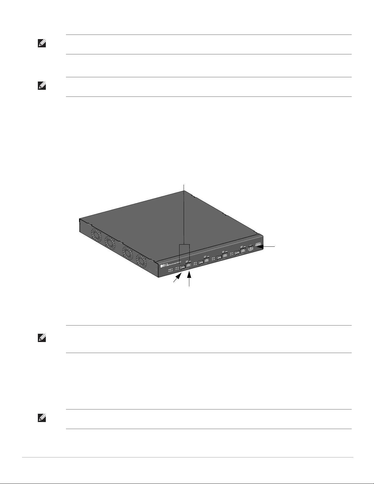
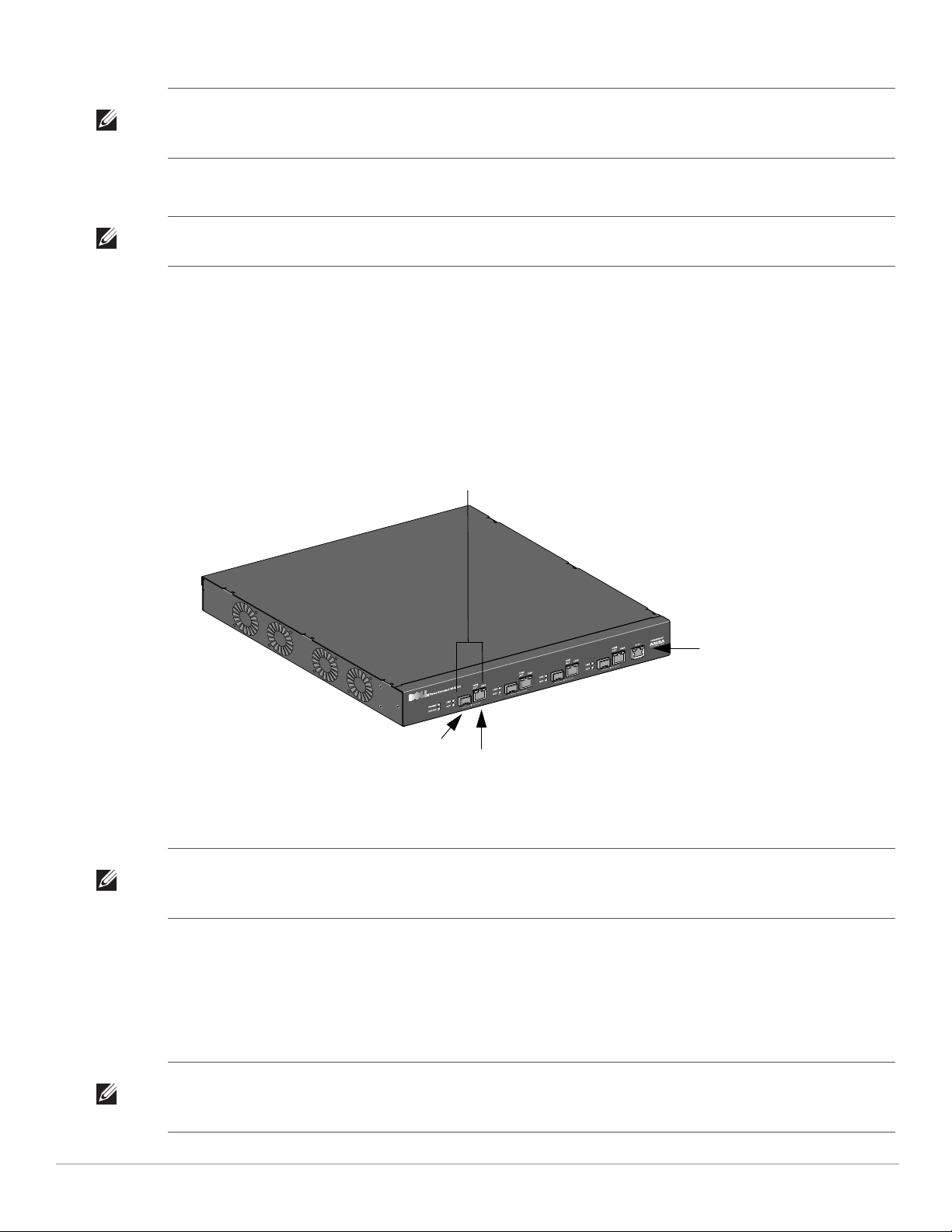
Serial Console Port
10/100/1000-Base-T Gigabit
Ethernet Port
1000BaseX (SFP) Ports
Dual-media ports (4x); 1000Base-X or
10/100/1000Base-T
original packing materials. Use these materials to repack and return the unit to the supplier if needed.
Note: Optional accessories, such as SFP modules, are available for use with the W-3000 Series Controllers and are sold
separately. Contact your Dell representative for details and assistance.
Model Overview
The physical hardware model overview of the W-3000 Series Controllers covers all three models within the series.
The difference between the three controller models is dependent on the licensing level purchased. The controller
model depicted in the illustrations throughout this chapter is the W-3200.
Figure 1 W-3200 Front View
Note: Ports zero through three are dual-media ports and can utilize either the 1000Base-X or 10/100/1000Base-T connections
provided. However, the 1000Base-X fiber connection has priority over the 10/100/1000Base-T copper connection. If a link is
detected for the 1000Base-X interface, the 10/100/1000Base-T connection will be disabled.
1000Base-X (SFP) Ports
There are four 1000Base-X combination ports for fiber connectivity only and are intended for use with Dell SFPs
(mini-GBICs).
To purchase compatible SFP modules, contact your Dell representative for details and assistance.
Note: Dell tests and supports Dell optics within their controller systems. Third party optics are not tested or supported; therefore,
Dell does not guarantee proper functionality of third party optics.
8 | About the PowerConnect W-3000 Series Controllers Dell PowerConnect W-3000 Series Controller | Installation Guide
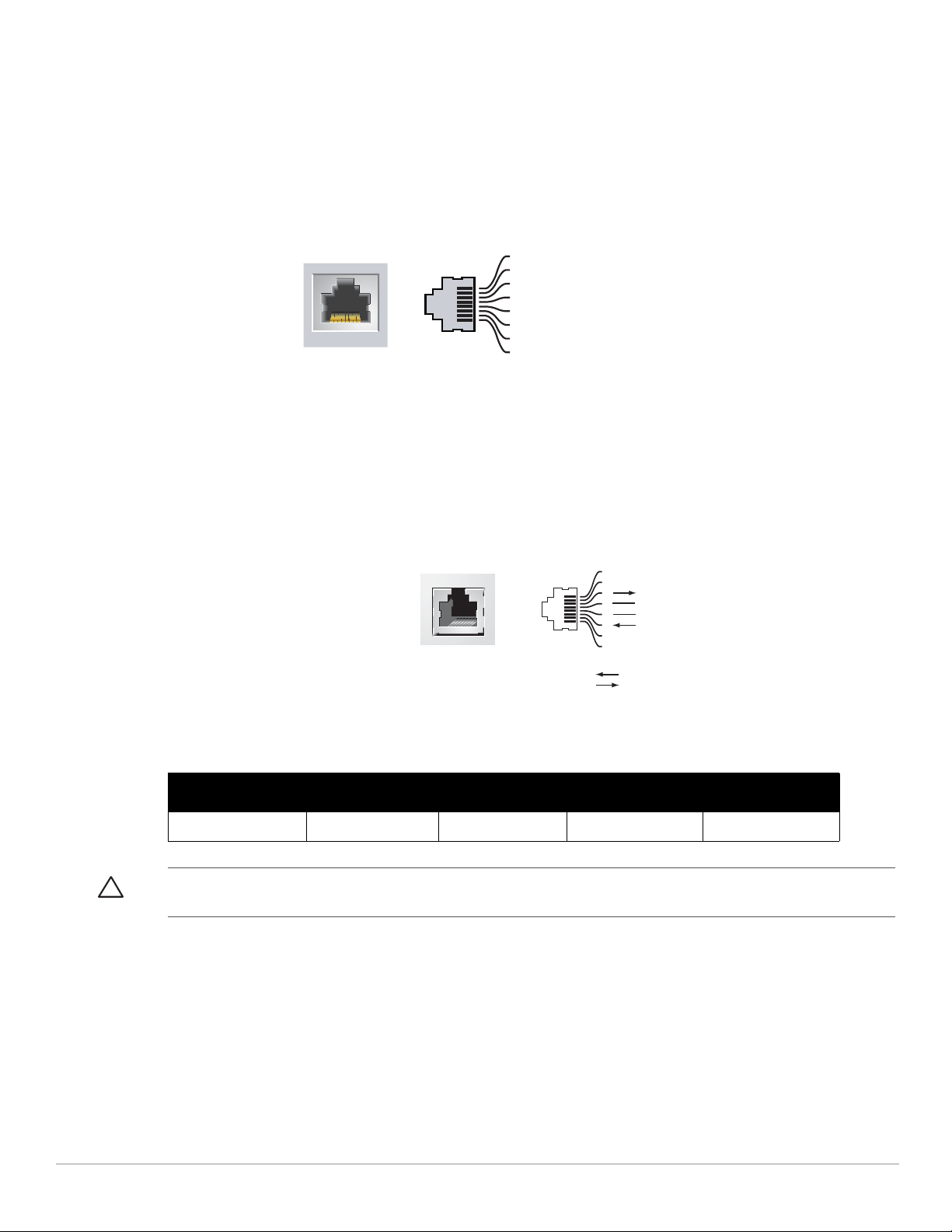
10/100/1000Base-T Gigabit Ethernet Ports
1000Base-T Gigabit
Ethernet Port
RJ-45 Female
Pin-Out
Signal Name
1
2
3
4
5
6
7
8
BI_DC+
BI_DC-
BI_DD+
BI_DD-
BI_DA+
BI_DABI_DB+
BI_DB-
Function
Bi-directional pair +C
Bi-directional pair -C
Bi-directional pair +D
Bi-directional pair -D
Bi-directional pair +A
Bi-directional pair -A
Bi-directional pair +B
Bi-directional pair -B
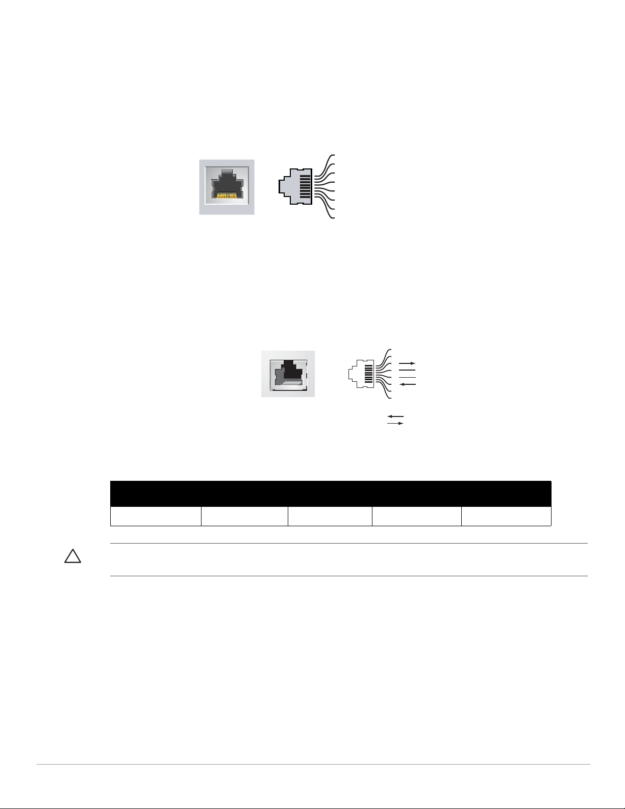
There are four 10/100/1000Base-T Gigabit Ethernet (RJ-45) ports. Gigabit Ethernet uses all eight wires and each
pair is used in a bi-directional fashion, meaning the same pairs are used for both data transmission and reception.
Figure 2 illustrates the CAT-5 pin-out found on an RJ-45 connector. The CAT-5 pin-out pairs the following pins
on a 10/100/1000Base-T Gigabit Ethernet port: 1/2, 3/6, 4/5, and 7/8.
Figure 2 Gigabit Ethernet Port Pin-Out
Serial Console Port
A serial console port is provided for connection to a terminal, allowing for direct local management. The port’s
RJ-45 female connector accepts an RS-232 serial cable with a male connector.
Figure 3 Serial Console Port Pin-Out
Serial
Console Port
RJ-45 Female
Pin-Out
Direction
Output
Input
1
2
3
4
5
6
7
8
TxD
GND
GND
RxD
Communication settings for the serial console port are indicated in Table 1.
Table 1 Console Terminal Settings
Baud Rate Data Bits Parity Stop Bits Flow Control
9600 8 None 1 None
Caution: Do not connect an Access Point (AP) to the serial console port. The serial console port is compatible with only RS-232
devices. Non-RS-232 devices, such as APs, are not supported.
Serial Console Port Adaptor
A modular adaptor can be used to convert the RJ-45 (female) connector to a DB9 (male) connector. Refer to
Figure 4 for complete details.
Dell PowerConnect W-3000 Series Controller | Installation Guide About the PowerConnect W-3000 Series Controllers | 9

Figure 4 RJ-45 (female) to DB9 (male) Modular Adaptor Conversion
3
4
5
2
5
63
RJ-45 DB-9
Internal
Connections
TxD
GND
RxD
1
2
3
4
5
6
7
8
TxD
GND
RxD
RJ-45 Female
Pin-Out
Direction
Input
Output
DB-9 Male
Pin-Out
TxD
RxD
Ground
5
4
3
2
1
9
8
7
6
Direction
Input
Output
AC Power Socket
Figure 5 represents the W-3200 rear view.
Figure 5 W-3200 Rear View
AC Power Socket
The W-3000 Series Controllers supports integrated AC powering and the AC power socket on the rear of the unit
is for use with an AC power cord (country-specific). Refer to “Power Management Specifications” on page17 for
power specification details.
LED Status Indicators
Table 2 W-3000 Series Controllers LED Status Indicators
LED Function Indicator Status
POWER Input Power Status
Indicator
STATUS Module Status Indicator On (Solid Green) Device is operational
10 | About the PowerConnect W-3000 Series Controllers Dell PowerConnect W-3000 Series Controller | Installation Guide
LNK 1000Base-X Ports Link Status Indicator On (Solid Green) Link has been established
On (Solid Green) Power on
Off No power
On (Solid Red) Device failed
On (Solid Amber) Device is loading software
Off No power
Off No link on port

Table 2 W-3000 Series Controllers LED Status Indicators
LED Function Indicator Status
ACT 1000Base-X ports Activity Status Indicator On (Blinking Green) Port is transmitting or receiving
data
Off No activity
LNK/ACT 10/100/1000Base-T Ports Link/Activity Status
Indicator
1000 10/100/1000Base-T Ports Interface Speed Indicator On (Solid Green) 1000 Mbps interface speed in use
On (Solid Green) Link has been established
On (Blinking Green) Port is transmitting or receiving
data
Off No link on port
Off 10/100 Mbps interface speed in
use
Dell PowerConnect W-3000 Series Controller | Installation Guide About the PowerConnect W-3000 Series Controllers | 11

12 | About the PowerConnect W-3000 Series Controllers Dell PowerConnect W-3000 Series Controller | Installation Guide

Chapter 2
Installing the W-3000 Series
Controllers
The following tools and equipment are required for installing the Dell PowerConnect W-3000 Series Controllers:
z Rack Mount Bracket (x2, not used for tabletop installation)
z Suitable Screwdrivers
z AC Power Cord (country-specific)
Warning: Before performing the following procedure, review the safety instructions that came with the controller.
For a Telecom Rack:
z 6-32 x 1/4” Phillips Head Screws (6x, included)
z 12-24 x 5/8” Phillips Head Screws (4x, included)
For a Server Rack:
z 6-32 x 1/4” Phillips Head Screws (6x, included)
z M6 x 20mm Phillips Head Screws (4x, included)
z M6 Cage Nuts (4x, inluded) or M6 Cage Clips (4x, inluded)
Installation in a Telecom Rack
To install the W-3000 Series Controllers into a 19-inch (48.26 cm) rack system:
1. Place a rack mount bracket over the mounting holes on one side of the controller (see Figure 1).
2. Secure the bracket to the controller using three 6-32 x 1/4” phillips flat head screws and a suitable screwdriver.
3. Repeat these steps on the opposite side of the controller.
Dell PowerConnect W-3000 Series Controller | Installation Guide Installing the W-3000 Series Controllers | 13
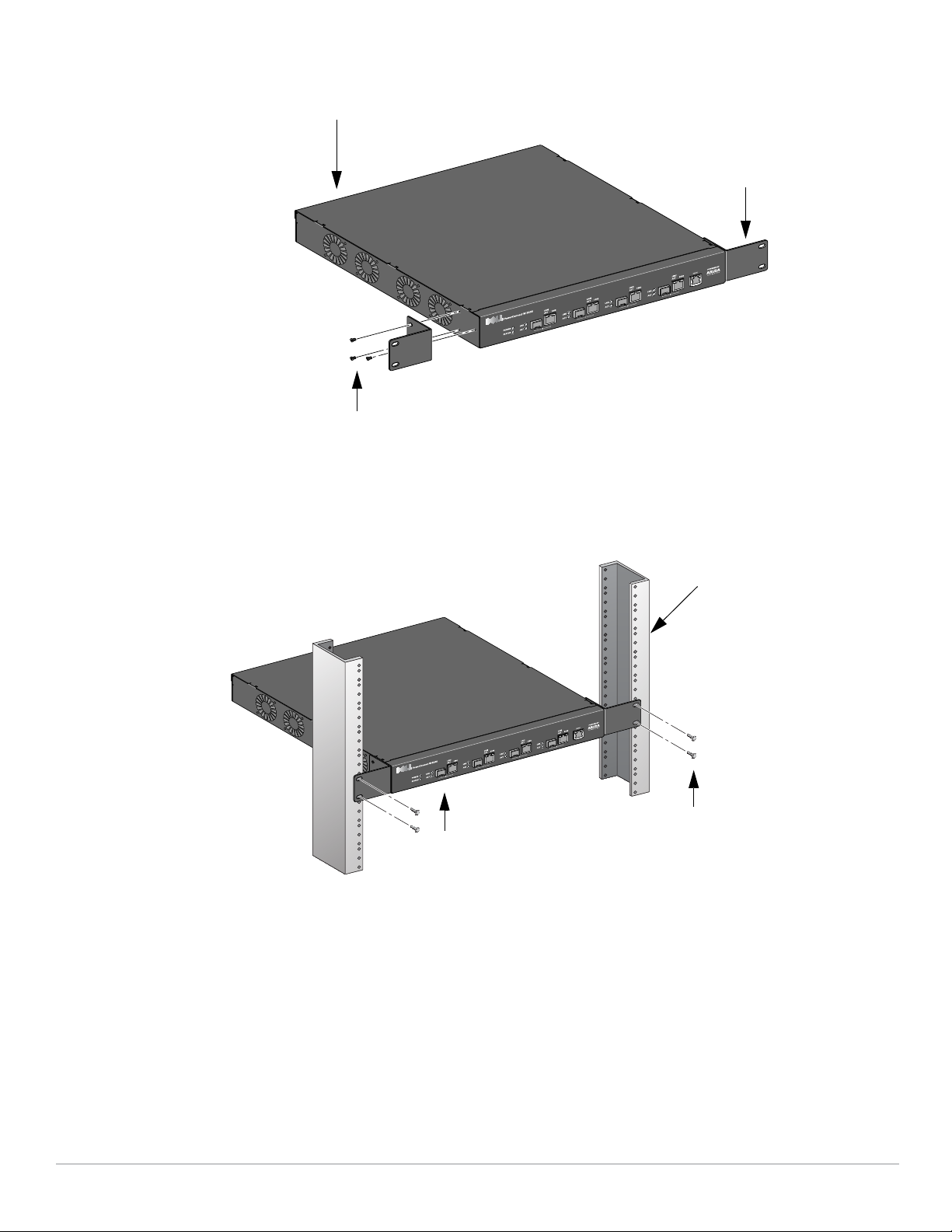
Figure 1 Rack Mount Brackets
Rack Mount Bracket (2x)
W-3000 Series Controllers MultiService Controller
6-32 x 1/4” Phillips Flat Head Screws (6x,
3x per bracket)
Standard 19-inch
Rack System
12-24 x 5/8”
Phillips Flat Head Screws
(4x, 2x per bracket)
W-3000 Series Controllers
Multi-Service Controller with Rack
Mount Brackets
4. Mount the controller within your organization’s rack system using four 12-24 x 5/8” phillips flat head screws
and a suitable screwdriver (see Figure 2).
Figure 2 Rack Mount Installation
5. Leave a minimum of four inches (10 cm) of space on the left and right side of the unit for proper air flow and
6. Leave additional space in the front and back of the unit to access power cords, network cables, and LED status
ventilation (see Figure 3).
indicators (see Figure 3).
14 | Installing the W-3000 Series Controllers Dell PowerConnect W-3000 Series Controller | Installation Guide
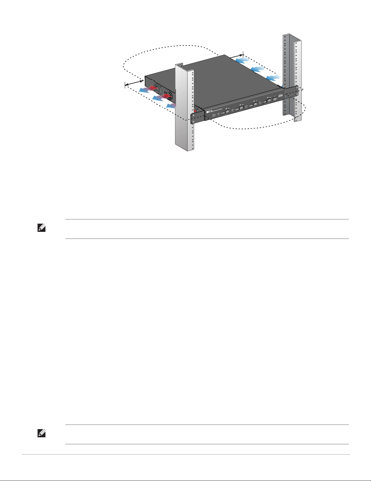
Figure 3 Air Flow Requirements
Keep Clear for
Air Exhaust
Keep Clear for Air Intake
Keep Open for
Easy Access
Keep Open for
Easy Access
4 inches (10
cm) Minimum
7. Connect the AC power cord (country-specific) to the rear of the unit.
8. Plug the opposite end of the power cord into an electrical outlet to power on the controller.
Installation in a Server Rack
To install a W-3000 Series Controllers controller into a 19-inch (48.26 cm) Server rack system:
Note: The following instructions describe the installation of your controller in a rack with unthreaded, square holes. For a rack
with unthreaded, round holes, use the provided clip nuts instead.
1. Place a rack mount bracket over the mounting holes on one side of the controller (see Figure 1).
2. Secure the bracket to the controller using three 6-32 x 1/4” phillips head screws and a suitable screwdriver.
3. Repeat these steps on the opposite side of the controller.
4. Install the four cage nuts.
a. Begin by inserting the lower lip of the cage but over the square opeing in the back of the rail.
b. Insert the small end of the cage-nut installation tool through the opening in the rail (from the front), and
hook the tool over the top lip of the cage nut.
c. Push the cage nut in towards the rail while rotating the tool up and pulling the tool back toward you until
the top lip of the cage nut snaps into position.
5. Mount the controller within your organization’s rack system using four M6 x 20mm phillips head screws and
suitable screwdriver.
6. Leave a minimum of four inches (10cm) of space on the left and right side of the unit for proper air flow and
ventilation (see Figure 3).
7. Leave additional space in front and back of the unit to access power cords, network cables, and LED status
indicators (see Figure 3).
8. Connect the AC power cord (country-specific) to the rear of the unit.
9. Plug the opposite end of the power cord into an electrical outlet to power the controller.
Note: W-3000 Series Controllers do not have a power on/off switch. Power to the unit is controlled by inserting (or unplugging) the
Dell PowerConnect W-3000 Series Controller | Installation Guide Installing the W-3000 Series Controllers | 15
power cord plug into your electric outlet.

Tabletop Deployment
To deploy an W-3000 Series Controllers on a flat surface, such as a tabletop:
1. Insert the four rubber mounting feet to the bottom of the unit.
2. Attach side bezels by snapping them into place.
3. Place the unit on a hard flat surface.
Initial Setup and Network Connectivity
Once the physical installation is complete, run the initial setup on the controller to configure the IP address and
other basic system information. For complete details and instructions, refer to the ArubaOS Quick Start Guide for
the software version installed on your controller.
Removal
To remove the W-3000 Series Controllers from a 19-inch (48.26 cm) rack system:
1. Disconnect the power to the controller by unplugging the power cord from the electrical outlet.
2. Disconnect any other cables or devices attached to the controller.
3. Loosen the four rack mount screws securing the controller to your organizations rack system.
4. Remove the controller from the rack system.
16 | Installing the W-3000 Series Controllers Dell PowerConnect W-3000 Series Controller | Installation Guide

Appendix A
Specifications, Safety &
Compliance
Physical Specifications
z Device Dimensions (without rack mount brackets) (HxWxD):
All Models: 1.75” x 13.8” x 11.7”
All Models: 44 mm x 351 mm x 297 mm
Device Weight (with rack mount brackets):
z W-3200: 7.1 lbs/3.2 kgs
z W-3400/W-3600: 7.4 lbs/3.4 kgs
z Shipping Dimensions (HxWxD):
All Models: 6.5” x 18.2” x 16.5”
All Models: 165 mm x 462 mm x 419 mm
z Shipping Weight:
W-3200: 9.4 lbs/4.3 kgs
W-3400/W-3600: 9.7 lbs/4.4 kgs
Power Management Specifications
Power Consumption
z W-3200: 35 W maximum
z W-3400: 45 W maximum
z W-3600: 60 W maximum
Power Specifications (AC Input Requirements)
z W-3200:
AC Input Voltage: 90-264 V~, Universal Input
AC Input Current: 1.5 A
AC Input Frequency: 47-63 Hz
z W-3400/W-3600:
AC Input Voltage: 90-264 V~, Universal Input
AC Input Current: 2.2 A
AC Input Frequency: 47-63 Hz
Operating Specifications
z Operating Temperature Range: 0°C to 40°C (32°F to 104°F)
z Operating Humidity Range: 5% to 95% (RH), non-condensing
Dell PowerConnect W-3000 Series Controller | Installation Guide Specifications, Safety & Compliance | 17
Storage Specifications
CLASS 1
LASER PRODUCT
z Storage Temperature Range: 0°C to 50°C (32°F to 122°F)
z Storage Humidity Range: 5% - 95% (RH), non-condensing
Safety and Regulatory Compliance
Dell provides a multi-language document containing country specific restrictions and additional safety and
regulatory information for all Dell hardware products. The Dell PowerConnect W-Series Safety, Environmental,
and Regulatory Information document is included with this product.
Caution: Use of controls or adjustments of performance or procedures other than those specified in this manual may result
in hazardous radiation exposure.
This product complies with 21 CFR Chapter 1, Subchapter J, Part 1040.10, and IEC 60825-1: 1993, A1: 1997, A2:
2001, IEC 60825-2: 2000.
For continued compliance with the above laser safety standards, only approved Class 1 modules from our
approved vendors should be installed in Dell products.
FCC Class A Device
This equipment has been tested and found to comply with the limits for a Class A digital device, pursuant to Part
15 of the FCC Rules. These limits are designed to provide reasonable protection against harmful interference
when the equipment is operated in a commercial environment. This equipment generates, uses, and can radiate
radio frequency energy and, if not installed and used in accordance with the instruction manual, may cause
harmful interference to radio communications. Operation of this equipment in a residential area is likely to cause
harmful interference in which case the user will be required to correct the interference at his own expense.
Industry Canada
This Class A digital apparatus complies with Canadian ICES-003.
Cet appareil numérique de la classe A est conforme à la norme NMB-003 du Canada.
18 | Specifications, Safety & Compliance Dell PowerConnect W-3000 Series Controller | Installation Guide

NOM Information (Mexico Only)
The following information is provided on the device described in this document in compliance with the
requirements of the official Mexican standards (NOM):
Importer: Dell Inc. de Mexico, S.A. de C.V.
Paseo de la Reforma 2620-11° Piso
Col. Lomas Atlas
11950 Mexico, D.F.
Model Number: 3200
z Supply Voltage: 90-264 V AC
z Frequency: 47-63 Hz
z Current consumption: 1.5 A
Model Number: 3400/3600
z Supply Voltage: 90-264 V AC
z Frequency: 47-63 Hz
z Current consumption: 2.2 A
Proper Disposal of Dell Equipment
For the most current information on Global Environmental Compliance and Dell products please see our website
at www.dell.com.
European Union RoHS
Dell products also comply with the EU Restriction of Hazardous Substances Directive
2002/95/EC (RoHS). EU RoHS restricts the use of specific hazardous materials in the
manufacture of electrical and electronic equipment. Specifically, restricted materials
under the RoHS Directive are Lead (including Solder used in printed circuit assemblies), Cadmium, Mercury,
Hexavalent Chromium, and Bromine. Some Dell products are subject to the exemptions listed in RoHS Directive
Annex 7 (Lead in solder used in printed circuit assemblies). Products and packaging will be marked with the
“RoHS” label shown at the left indicating conformance to this Directive.
Dell PowerConnect W-3000 Series Controller | Installation Guide Specifications, Safety & Compliance | 19

July 2010 | 0510762-MU-01 Dell PowerConnect W-3000 Series Controller | Installation Guide

Dell PowerConnect
W-3000 Serie Controller
Installationsanleitung

Copyright
© 2010 Aruba Networks, Inc. AirWave®, Aruba Networks®, Aruba Mobility Management System®, und andere eingetragene Marken
sind Marken von Aruba Networks, Inc. Dell™, das DELL™-Logo und PowerConnect™ sind Marken von Dell Inc.
Alle Rechte vorbehalten. Spezifikationen in diesem Handbuch können ohne Ankündigung geändert werden.
Hergestellt in den USA. Alle anderen Marken, die in diesem Handbuch erwähnt werden, sind das Eigentum der jeweiligen
Unternehmen.
Open Source Code
Bestimmte Aruba-Produkte enthalten Open Source-Softwarecode, der von Drittanbietern entwickelt wurde, darunter Softwarecode
gemäß GNU General Public License (GPL), GNU Lesser General Public License (LGPL) oder anderen Open Source-Lizenzen. Den Open
Source Code finden Sie auf dieser Website:
http://www.arubanetworks.com/open_source
Rechtliche Hinweise
Die Verwendung von Switching-Plattformen und Software von Aruba Networks, Inc. durch Einzelpersonen oder Unternehmen zur
Terminierung von VPN-Client-Geräten anderer Hersteller stellt die vollständige Anerkennung der Haftbarkeit dieser Einzelpersonen oder
dieses Unternehmens für diese Aktion dar und enthebt Aruba Networks, Inc. zur Gänze aller rechtlichen Maßnahmen, die bezüglich der
Verletzung des Urheberrechts im Namen dieser Hersteller ergriffen werden.
Dell PowerConnect W-3000 Serie Controller | Installationsanleitung 0510762-MU-01 | Juli 2010

Inhalt
Zu diesem Handbuch................................................................................................................................................5
Übersicht über das Handbuch .........................................................................................................5
Verwandte Dokumente......................................................................................................................5
Kontaktaufnahme mit Dell................................................................................................................. 5
Kapitel 1 PowerConnect W-3000 Serie Controller .........................................................................7
Mindestvoraussetzungen für die Software.................................................................................... 7
Checkliste ............................................................................................................................................7
Modellübersicht.................................................................................................................................. 8
1000Base-X (SFP)-Ports ............................................................................................................8
10/100/1000Base-T-Gigabit-Ethernet-Ports ...........................................................................9
Serielle Konsolenschnittstelle ................................................................................................. 9
Adapter für die serielle Konsolenschnittstelle.............................................................. 9
Netzstromanschluss ................................................................................................................10
LED-Statusanzeigen.................................................................................................................10
Kapitel 2 Installieren des W-3000 Serie Controller .....................................................................13
Bei Verwendung eines Telecom-Racks: ..............................................................................13
Bei Verwendung eines Server-Racks:..................................................................................13
Installation in einem Telecom-Rack..............................................................................................13
Installation in einem Server-Rack .................................................................................................15
Aufstellung......................................................................................................................................... 16
Erstmalige Einrichtung und Netzwerkkonnektivität.................................................................... 16
Ausbau ...............................................................................................................................................16
Anhang A Technische Daten, Sicherheit und Konformität...........................................................17
Physische Spezifikationen ..............................................................................................................17
Stromversorgungsspezifikationen.................................................................................................17
Stromverbrauch........................................................................................................................17
Energiespezifikationen (AC-Eingangsanforderungen).......................................................17
Betriebsspezifikationen...................................................................................................................17
Lagerungsspezifikationen....................................................................................................... 18
Sicherheits- und Zulassungsbestimmungen ...............................................................................18
FCC Class A-Gerät.................................................................................................................... 18
Industry Canada........................................................................................................................18
NOM-Informationen (nur Mexiko)......................................................................................... 19
Ordnungsgemäße Entsorgung von Dell-Geräten........................................................................ 19
RoHS-Richtlinie der Europäischen Union ............................................................................19
Dell PowerConnect W-3000 Serie Controller | Installationsanleitung Inhalt | 3

4 | Inhalt Dell PowerConnect W-3000 Serie Controller | Installationsanleitung

Zu diesem Handbuch
Dieses Vorwort enthält die folgenden Informationen:
z „Übersicht über das Handbuch“ auf Seite 5
z „Verwandte Dokumente“ auf Seite 5
z „Kontaktaufnahme mit Dell“ auf Seite 5
Übersicht über das Handbuch
z Kapitel 1, „PowerConnect W-3000 Serie Controller“ auf Seite 7 enthält einen ausführlichen Überblick über
die Hardware der drei Controller der W-3000 Serie: W-3200, W-3400 und W-3600.
z Kapitel 2, „Installieren des W-3000 Serie Controller“ auf Seite 13 bietet Informationen zur Rack-Montage
und Installation
z Anhang A, „Technische Daten, Sicherheit und Konformität“ auf Seite 17 enthält technische Daten und
Informationen zur Sicherheit und Richtlinienkonformität.
Verwandte Dokumente
Die folgenden Dokumente und Anleitungen werden im vorliegenden Handbuch als Referenz angegeben und
gelten als Bestandteile der vollständigen Dokumentation, die für die erfolgreiche Bereitstellung und Verwaltung
eines Dell Controllers erforderlich ist.
z
Dell PowerConnect ArubaOS Quick Start Guide
z
Dell PowerConnect ArubaOS User Guide
z
Dell PowerConnect ArubaOS 5.0 Command Line Reference
Kontaktaufnahme mit Dell
Website-Support
Hauptsite www.dell.com
Support-Site support.dell.com
Dell-Dokumentation support.dell.com/manuals
Dell PowerConnect W-3000 Serie Controller | Installationsanleitung Zu diesem Handbuch | 5

6 | Zu diesem Handbuch Dell PowerConnect W-3000 Serie Controller | Installationsanleitung

Kapitel 1
PowerConnect W-3000 Serie
Controller
Der PowerConnect W-3000 Serie Controller besteht aus drei drahtlosen LAN-Controllern der Enterprise-Klasse.
Diese Controller verbinden, steuern und integrieren auf intelligente Weise drahtlose Access Points (APs) und Air
Monitors (AMs) in ein kabelgebundenes LAN-System.
Die PowerConnect W-3000 Serie Controller besteht aus den folgenden Modellen:
z W-3200 Multiservice Controller
Der W-3200 unterstützt bis zu 32 verbundene APs auf einem Gelände.
z W-3400 Multiservice Controller
Der W-3400 unterstützt bis zu 64 verbundene APs auf einem Gelände.
z W-3600 Multiservice Controller
Der W-3600 unterstützt bis zu 128 verbundene APs auf einem Gelände.
Hinweis: Funktionsbezogene AP-Lizenzen werden unabhängig voneinander und zusätzlich zu den AP-Upgradelizenzen gezählt.
Wenden Sie sich an Ihren Dell-Kundenbetreuer, um sich ausführlich über Softwarelizenzierungsoptionen und Supportkapazitäten
zu informieren.
Mindestvoraussetzungen für die Software
Der W-3000 Serie Controller erfordert ArubaOS 5.0.2 oder höher.
Hinweis: Der Master-Controller, sein redundanter Master-Controller und alle lokalen Controller müssen dieselbe Version von
ArubaOS verwenden. Wenn Sie Ihr Netzwerk aktualisieren und einen W-3000 Serie Controller im Netzwerk installieren,
vergewissern Sie sich, dass die Softwareversion des Controllers zum restlichen Netzwerk passt. Wenn die mit dem Controller
gelieferte Version älter ist als die Version, auf die Sie Ihr Netzwerk aktualisiert haben, müssen Sie den Code auf dem Controller
aktualisieren, damit er mit dem des Netzwerks übereinstimmt.
Checkliste
z W-3000 Serie Controller
z Netzkabel (länderspezifisch)
z Rack-Montagehalterungen mit Schrauben (für die Rack-Montage)
z Serielles Flachbandkabel (RJ-45)
z Gummifüße (für die Aufstellung auf Tischplatten)
z Adapter für die serielle Konsolenschnittstelle (RJ-45 zu DB9)
z
Dell PowerConnect ArubaOS Quick Start Guide
z Endbenutzerlizenzvereinbarung (EULA)
z Safety, Environmental, and Regulatory Information (SERI)-Dokument
z Warranty and Support Information (WSI)-Dokument
Dell PowerConnect W-3000 Serie Controller | Installationsanleitung PowerConnect W-3000 Serie Controller | 7
Hinweis: Wenden Sie sich an Ihren Händler, wenn Teile fehlen oder beschädigt sind oder wenn Sie falsche Teile erhalten haben.
Serielle
Konsolenschnittstelle
10/100/1000Base-T-GigabitEthernet-Port
1000BaseX (SFP)-Ports
Dual-Media-Ports (4x); 1000Base-X
oder 10/100/1000Base-T
Bewahren Sie den Karton einschließlich der Original-Verpackungsmaterialien nach Möglichkeit auf. Verwenden Sie diese
Materialien, um das Produkt bei Bedarf zu verpacken und zum Händler zurückzubringen.
Hinweis: Optionales Zubehör, zum Beispiel SFP-Module, zur Verwendung mit dem W-3000 Serie Controller kann separat
erworben werden. Wenden Sie sich an Ihren Dell-Kundenbetreuer, um weitere Informationen und Beratung zu erhalten.
Modellübersicht
Die Hardware-Modellübersicht des W-3000 Serie Controllers deckt alle drei Modelle dieser Serie ab.
Der Unterschied zwischen den drei Controller-Modellen besteht im jeweils erworbenen Lizenzumfang.
Das in den Abbildungen in diesem Kapitel dargestellte Controller-Modell ist der W-3200.
Abbildung 1 W-3200 Vorderansicht
Hinweis: Die Anschlüsse 0 bis 3 sind Dual-Media-Ports und können 1000Base-X- oder 10/100/1000Base-T-Verbindungen nutzen.
Die 1000Base-X-Glasfaserverbindung hat jedoch Vorrang vor der 10/100/1000Base-T-Kupferkabelverbindung. Wenn eine
Verbindung für die 1000Base-X-Schnittstelle erkannt wird, wird die 10/100/1000Base-T-Verbindung deaktiviert.
1000Base-X (SFP)-Ports
Es stehen vier 1000Base-X-Kombinations-Ports ausschließlich für faseroptische Konnektivität zur Verfügung.
Sie sind zur Verwendung mit Dell SFP-Modulen (Mini-GBICs) konzipiert.
Wenn Sie kompatible SFP-Module erwerben möchten, wenden Sie sich an Ihren Dell-Kundenbetreuer.
Hinweis: Dell testet und unterstützt Glasfaserleitungen von Dell innerhalb der Controllersysteme. Faseroptische Leitungen anderer
Hersteller werden nicht getestet oder unterstützt; Dell kann deshalb die einwandfreie Funktionalität von Glasfaserleitungen anderer
Hersteller nicht garantieren.
8 | PowerConnect W-3000 Serie Controller Dell PowerConnect W-3000 Serie Controller | Installationsanleitung
10/100/1000Base-T-Gigabit-Ethernet-Ports
1000Base-T Gigabit-
Ethernet-Port
RJ-45-Buchse
Pin-Belegung
Signalname
1
2
3
4
5
6
7
8
BI_DC+
BI_DC-
BI_DD+
BI_DD-
BI_DA+
BI_DABI_DB+
BI_DB-
Funktion
Bidirektionales Paar +C
Bidirektionales Paar -C
Bidirektionales Paar +D
Bidirektionales Paar -D
Bidirektionales Paar +A
Bidirektionales Paar -A
Bidirektionales Paar +B
Bidirektionales Paar -B
Es gibt vier 10/100/1000Base-T Gigabit-Ethernet-Ports (RJ-45). Gigabit-Ethernet nutzt alle acht Leitungen und
jedes Paar wird bidirektional verwendet, sodass dieselben Paare sowohl für die Datenübertragung als auch für
den Empfang verwendet werden. Abbildung 2 zeigt die CAT-5-Pin-Belegung für einen RJ-45-Anschluss. Die
CAT-5-Pin-Belegung fasst jeweils die folgenden Pins bei einem 10/100/1000Base-T-Gigabit-Ethernet-Anschluss
zu Paaren zusammen: 1/2, 3/6, 4/5 und 7/8.
Abbildung 2 Pin-Belegung des Gigabit-Ethernet-Ports
Serielle Konsolenschnittstelle
Eine serielle Konsolenschnittstelle steht für den Anschluss an ein Terminal zur Verfügung, um die direkte
lokale Verwaltung zu ermöglichen. An die RJ-45-Buchse kann ein serielles Kabel (RS-232) mit Stecker
angeschlossen werden.
Abbildung 3 Serielle Konsolenschnittstelle - Pin-Belegung
Serielle
Konsolenschnittstelle
Kommunikationseinstellungen für die serielle Konsolenschnittstelle sind in Tabelle 1 aufgeführt.
RJ-45-Buchse
Pin-Belegung
Richtung
Eingang
Ausgang
1
2
3
4
5
6
7
8
TxD
GND
GND
RxD
Tabelle 1 Konsolenterminaleinstellungen
Baudrate Datenbits Parität Stoppbits Flusssteuerung
9600 8 Keine 1 Keine
Vorsicht: Schließen Sie keinen Access Point (AP) an die serielle Konsolenschnittstelle an. Die serielle Konsolenschnittstelle ist
nur mit RS-232-Geräten kompatibel. Andere Geräte als RS-232-Geräte, zum Beispiel APs, werden nicht unterstützt.
Adapter für die serielle Konsolenschnittstelle
Dell PowerConnect W-3000 Serie Controller | Installationsanleitung PowerConnect W-3000 Serie Controller | 9
Mit einem modularen Adapter kann die RJ-45-Buchse in einen DB9-Stecker umgewandelt werden.
Details können Sie Abbildung 4 entnehmen.
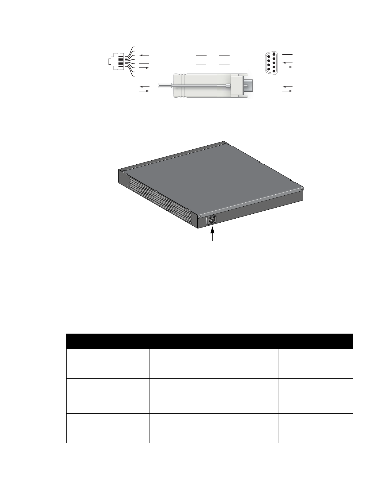
Abbildung 4 Umwandlung der RJ-45-Buchse zum DB-9-Stecker mit modularem Adapter
3
4
5
2
5
63
RJ-45 DB-9
Interne
Verbindungen
TxD
GND
RxD
1
2
3
4
5
6
7
8
TxD
GND
RxD
RJ-45-Buchse
Pin-Belegung
Richtung
Eingang
Ausgang
DB-9-Stecker
Pin-Belegung
TxD
RxD
Masse
5
4
3
2
1
9
8
7
6
Richtung
Eingang
Ausgang
Netzstromanschluss
Abbildung 5 zeigt die Rückseite des W-3200.
Abbildung 5 W-3200 Rückansicht
Netzstromanschluss
Der W-3000 Serie Controller unterstützt die integrierte Netzstromversorgung. An den Netzstromanschluss auf
der Rückseite des Geräts kann ein Netzkabel angeschlossen werden (länderspezifisch). Weitere Informationen
zur Stromversorgung finden Sie unter „Stromversorgungsspezifikationen“ auf Seite 17.
LED-Statusanzeigen
Tabelle 2 W-3000 Serie Controller LED-Statusanzeigen
LED Funktion Anzeige Status
POWER Statusanzeige des
Eingangsstroms
STATUS Statusanzeige des Moduls Ein (durchgehend grün) Gerät ist betriebsbereit
10 | PowerConnect W-3000 Serie Controller Dell PowerConnect W-3000 Serie Controller | Installationsanleitung
LNK 1000Base-X-Ports Anzeige des
Verbindungsstatus
Ein (durchgehend grün) Stromversorgung ein
Aus Kein Strom
Ein (durchgehend rot) Gerätefehler
Ein (durchgehend gelb) Gerät lädt Software
Aus Kein Strom
Ein (durchgehend grün) Verbindung wurde hergestellt
 Loading...