

Page 1

Inspiron 23
Owner's Manual
Computer Model: Inspiron 23 Model 5348
Regulatory Model: W10C
Regulatory Type: W10C001
Page 2
Notes, Cautions, and Warnings
NOTE: A NOTE indicates important information that helps you make better
use of your computer.
CAUTION: A CAUTION indicates either potential damage to hardware or loss
of data and tells you how to avoid the problem.
WARNING: A WARNING indicates a potential for property damage, personal
injury, or death.
Copyright © 2014 Dell Inc. All rights reserved. This product is protected by U.S. and
international copyright and intellectual property laws. Dell™ and the Dell logo are trademarks
of Dell Inc. in the United States and/or other jurisdictions. All other marks and names
mentioned herein may be trademarks of their respective companies.
2014 - 03
Rev. A00
Page 3

Contents
Before Working Inside Your Computer.................................. 10
Before You Begin ............................................................................................ 10
Safety Instructions........................................................................................... 10
Recommended Tools.......................................................................................11
After Working Inside Your Computer......................................13
Technical Overview......................................................................14
Inside View of Your Computer........................................................................ 14
System Board Components.............................................................................15
Removing the Stand Assembly.................................................. 17
Procedure......................................................................................................... 17
Replacing the Stand Assembly..................................................20
Procedure........................................................................................................ 20
Removing the Back Cover.......................................................... 21
Prerequisites.....................................................................................................21
Procedure.........................................................................................................21
Replacing the Back Cover.......................................................... 23
Procedure.........................................................................................................23
Post-requisites................................................................................................. 23
Removing the Speaker Cover....................................................24
Prerequisites.....................................................................................................24
Procedure........................................................................................................ 24
Page 4

Replacing the Speaker Cover.................................................... 25
Procedure.........................................................................................................25
Post-requisites................................................................................................. 25
Removing the Speakers.............................................................. 26
Prerequisites.....................................................................................................26
Procedure........................................................................................................ 26
Replacing the Speakers...............................................................28
Procedure........................................................................................................ 28
Post-requisites.................................................................................................28
Removing the Memory Module(s)............................................29
Prerequisites.....................................................................................................29
Procedure........................................................................................................ 30
Replacing the Memory Module(s)............................................ 32
Procedure.........................................................................................................33
Post-requisites.................................................................................................34
Removing the System-Board Shield........................................35
Prerequisites.....................................................................................................35
Procedure.........................................................................................................35
Replacing the System-Board Shield........................................ 36
Procedure........................................................................................................ 36
Post-requisites.................................................................................................36
Removing the Hard Drive........................................................... 37
Prerequisites.....................................................................................................37
Procedure........................................................................................................ 38
Page 5

Replacing the Hard Drive...........................................................40
Procedure........................................................................................................ 40
Post-requisites.................................................................................................40
Removing the VESA-Mount Bracket........................................41
Prerequisites.....................................................................................................41
Procedure.........................................................................................................41
Replacing the VESA-Mount Bracket........................................42
Procedure........................................................................................................ 42
Post-requisites.................................................................................................42
Removing the Control-Buttons Board................................... 43
Prerequisites.....................................................................................................43
Procedure........................................................................................................ 43
Replacing the Control-Buttons Board....................................45
Procedure........................................................................................................ 45
Post-requisites.................................................................................................45
Removing the Converter Board................................................46
Prerequisites.................................................................................................... 46
Procedure........................................................................................................ 46
Replacing the Converter Board................................................48
Procedure........................................................................................................ 48
Post-requisites.................................................................................................48
Removing the Power-Supply Diagnostic Board.................. 49
Prerequisites.................................................................................................... 49
Procedure........................................................................................................ 49
Page 6

Replacing the Power-Supply Diagnostic Board....................51
Procedure.........................................................................................................51
Post-requisites................................................................................................. 51
Removing the Microphone........................................................ 52
Prerequisites.....................................................................................................52
Procedure.........................................................................................................52
Replacing the Microphone........................................................ 54
Procedure........................................................................................................ 54
Post-requisites.................................................................................................54
Removing the Wireless Card..................................................... 55
Prerequisites.....................................................................................................55
Procedure.........................................................................................................55
Replacing the Wireless Card......................................................56
Procedure........................................................................................................ 56
Post-requisites.................................................................................................56
Removing the Coin-Cell Battery...............................................57
Prerequisites.....................................................................................................57
Procedure........................................................................................................ 58
Replacing the Coin-Cell Battery...............................................59
Procedure........................................................................................................ 59
Post-requisites.................................................................................................59
Removing the I/O Bracket......................................................... 60
Prerequisites.................................................................................................... 60
Procedure.........................................................................................................61
Page 7

Replacing the I/O Bracket..........................................................63
Procedure........................................................................................................ 63
Post-requisites.................................................................................................63
Removing the Optical Drive...................................................... 64
Prerequisites.................................................................................................... 64
Procedure........................................................................................................ 65
Replacing the Optical Drive.......................................................68
Procedure........................................................................................................ 68
Post-requisites.................................................................................................68
Removing the Power-Supply Fan............................................ 69
Prerequisites.................................................................................................... 69
Procedure........................................................................................................ 70
Replacing the Power-Supply Fan............................................. 72
Procedure.........................................................................................................72
Post-requisites................................................................................................. 72
Removing the Power-Supply Unit............................................73
Prerequisites.....................................................................................................73
Procedure.........................................................................................................73
Replacing the Power-Supply Unit............................................76
Procedure.........................................................................................................76
Post-requisites................................................................................................. 76
Removing the Processor Heat-Sink.........................................77
Prerequisites.....................................................................................................77
Procedure.........................................................................................................77
Page 8

Replacing the Processor Heat-Sink.........................................79
Procedure.........................................................................................................79
Post-requisites................................................................................................. 79
Removing the Processor Fan.................................................... 80
Prerequisites.................................................................................................... 80
Procedure........................................................................................................ 80
Replacing the Processor Fan.....................................................82
Procedure........................................................................................................ 82
Post-requisites.................................................................................................82
Removing the Processor............................................................ 83
Prerequisites.....................................................................................................83
Procedure........................................................................................................ 83
Replacing the Processor.............................................................85
Procedure........................................................................................................ 85
Post-requisites.................................................................................................86
Removing the System Board..................................................... 87
Prerequisites.....................................................................................................87
Procedure........................................................................................................ 88
Replacing the System Board......................................................91
Procedure.........................................................................................................91
Post-requisites................................................................................................. 91
Entering the Service Tag in the BIOS..............................................................92
Removing the Camera................................................................ 93
Prerequisites.....................................................................................................93
Procedure........................................................................................................ 94
Page 9

Replacing the Camera.................................................................95
Procedure........................................................................................................ 95
Post-requisites.................................................................................................95
Removing the Antenna............................................................... 97
Prerequisites.....................................................................................................97
Procedure.........................................................................................................97
Replacing the Antenna............................................................... 99
Procedure........................................................................................................ 99
Post-requisites.................................................................................................99
Removing the Display Panel.................................................... 101
Prerequisites...................................................................................................101
Procedure...................................................................................................... 102
Replacing the Display Panel.................................................... 108
Procedure...................................................................................................... 108
Post-requisites...............................................................................................109
Flashing the BIOS........................................................................110
Getting Help and Contacting Dell.......................................... 111
Self-Help Resources.......................................................................................111
Contacting Dell...............................................................................................111
Page 10
Before Working Inside Your Computer
CAUTION: To avoid damaging the components and cards, handle
them by their edges and avoid touching pins and contacts.
Before You Begin
1 Save and close all open files and exit all open applications.
2 Shut down your computer.
– Windows 8: Move your mouse pointer to the upper-right or lower-
right corner of the screen to open the charms sidebar, and then click
or tap Settings → Power → Shut down.
– Windows 7: Click or tap Start → Shut down .
NOTE: If you are using a different operating system, see the
documentation of your operating system for shut-down
instructions.
3 Disconnect your computer and all attached devices from their electrical
outlets.
4 Disconnect all cables such as telephone cables, network cables and so
on, from your computer.
5 Disconnect all attached devices and peripherals, such as keyboard,
mouse, monitor, and so on, from your computer.
6 Remove any media card and optical disc from your computer, if
applicable.
7 After the computer is unplugged, press and hold the power button for 5
seconds to ground the system board.
CAUTION: Place the computer on a flat, soft and clean surface to
avoid scratching the display.
8 Place the computer face down.
Safety Instructions
Use the following safety guidelines to protect your computer from potential
damage and ensure your personal safety.
10
Page 11

WARNING: Before working inside your computer, read the safety
information that shipped with your computer. For more safety best
practices, see the Regulatory Compliance home page at dell.com/
regulatory_compliance.
WARNING: Disconnect all power sources before opening the
computer cover or panels. After you finish working inside the
computer, replace all covers, panels, and screws before connecting to
the power source.
CAUTION: To avoid damaging the computer, make sure that the work
surface is flat and clean.
CAUTION: To avoid damaging the components and cards, handle
them by their edges and avoid touching pins and contacts.
CAUTION: Only a certified service technician is authorized to remove
the computer cover and access any of the components inside the
computer. See the safety instructions for complete information about
safety precautions, working inside your computer, and protecting
against electrostatic discharge.
CAUTION: Before touching anything inside your computer, ground
yourself by touching an unpainted metal surface, such as the metal at
the back of the computer. While you work, periodically touch an
unpainted metal surface to dissipate static electricity, which could
harm internal components.
CAUTION: When you disconnect a cable, pull on its connector or on
its pull-tab, not on the cable itself. Some cables have connectors with
locking tabs or thumb-screws that you must disengage before
disconnecting the cable. When disconnecting cables, keep them
evenly aligned to avoid bending any connector pins. When connecting
cables, make sure that the ports and connectors are correctly oriented
and aligned.
CAUTION: To disconnect a network cable, first unplug the cable from
your computer and then unplug the cable from the network device.
CAUTION: Press and eject any installed card from the media-card
reader.
Recommended Tools
The procedures in this document may require the following tools:
11
Page 12

• Philips screwdriver
• Flat-head screwdriver
• Plastic scribe
12
Page 13

After Working Inside Your Computer
CAUTION: Leaving stray or loose screws inside your computer may
severely damage your computer.
1 Replace all screws and make sure that no stray screws remain inside your
computer.
2 Connect any external devices, peripherals, and cables you removed
before working on your computer.
3 Replace any media cards, discs, and any other part(s) that you removed
before working on your computer.
4 Connect your computer and all attached devices to their electrical
outlets.
5 Turn on your computer.
13
Page 14
Technical Overview
WARNING: Before working inside your computer, read the safety
information that shipped with your computer and follow the steps in
Before Working Inside Your Computer. After working inside your
computer, follow the instructions in After Working Inside Your
Computer. For more safety best practices, see the Regulatory
Compliance home page at dell.com/regulatory_compliance.
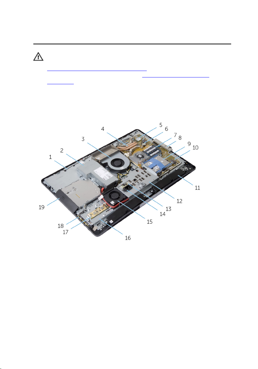
Inside View of Your Computer
1 antennas (2) 2 power-supply unit
3 processor fan 4 processor heat-sink
5 wireless card 6 coin-cell battery
7 memory modules (2) 8 side I/O bracket
9 hard-drive assembly 10 system board
11 speakers (2) 12 I/O bracket
13 power-supply diagnostic board 14 power port
15 power-supply fan 16 display-panel base
14
Page 15

17 converter board 18 control-buttons board
19 optical-drive assembly
System Board Components
1 processor socket 2 camera-cable connector
3 Mini Card slot 4 coin-cell battery socket
5 memory-module connectors (2) 6 speaker-cable connector
7 display-cable connector 8 control-buttons board cable
connector
9 converter-board cable connector 10 optical-drive power cable
connector
11 main power-cable connector 12 hard-drive connector
15
Page 16

13 optical-drive data cable
connector
15 power-supply fan cable
connector
17 video-card heat sink 18 processor power-cable
19 processor-fan cable connector
14 touch-control board cable
connector
16 video-card fan cable connector
connector
16
Page 17
Removing the Stand Assembly
WARNING: Before working inside your computer, read the safety
information that shipped with your computer and follow the steps in
Before Working Inside Your Computer. After working inside your
computer, follow the instructions in After Working Inside Your
Computer. For more safety best practices, see the Regulatory
Compliance home page at dell.com/regulatory_compliance.
Procedure
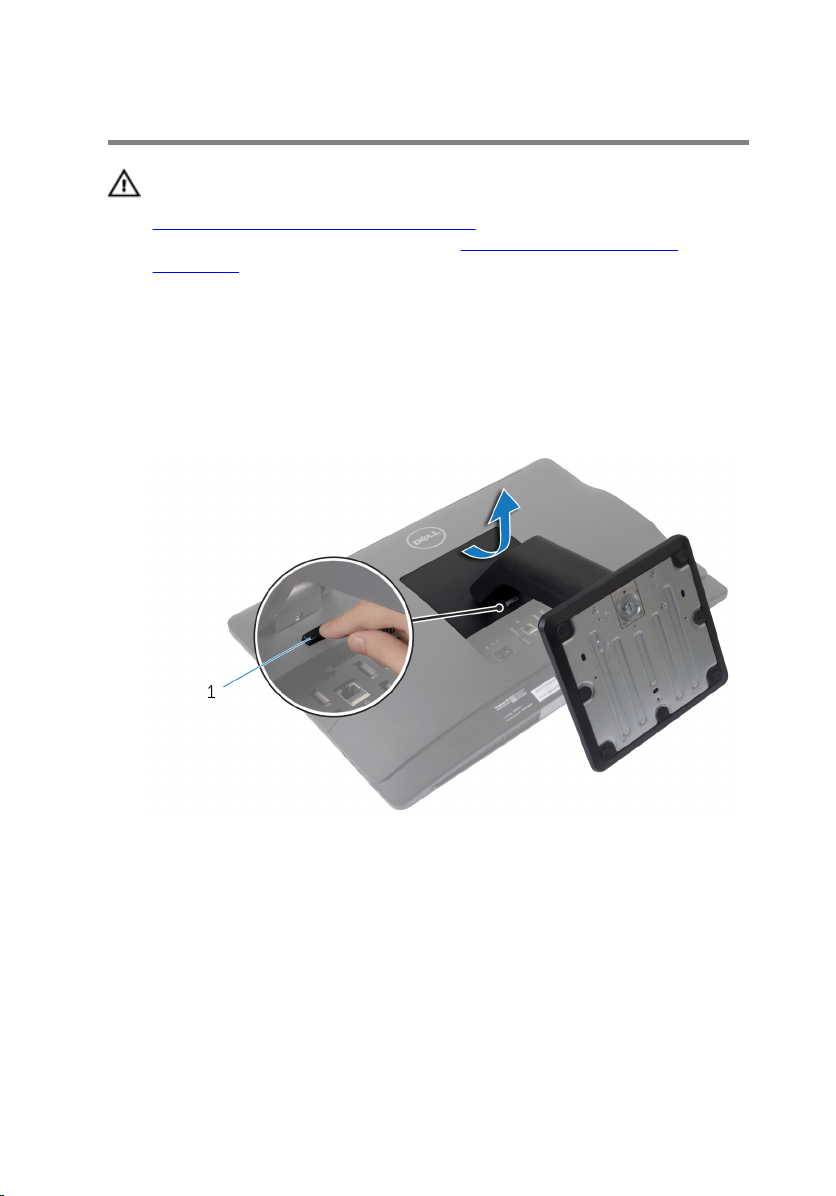
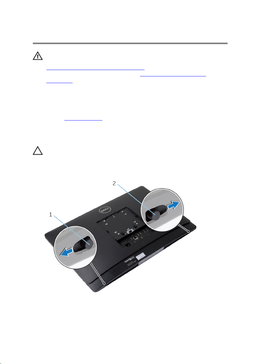
1 Press the stand-release button to release the stand.
2 Pivot the stand upward and remove the stand assembly away from the
computer.
1 stand-release button
If you need to remove either the stand base or stand riser from the stand
assembly, follow the steps below:
3 Release the screw handle on the stand base.
17
Page 18
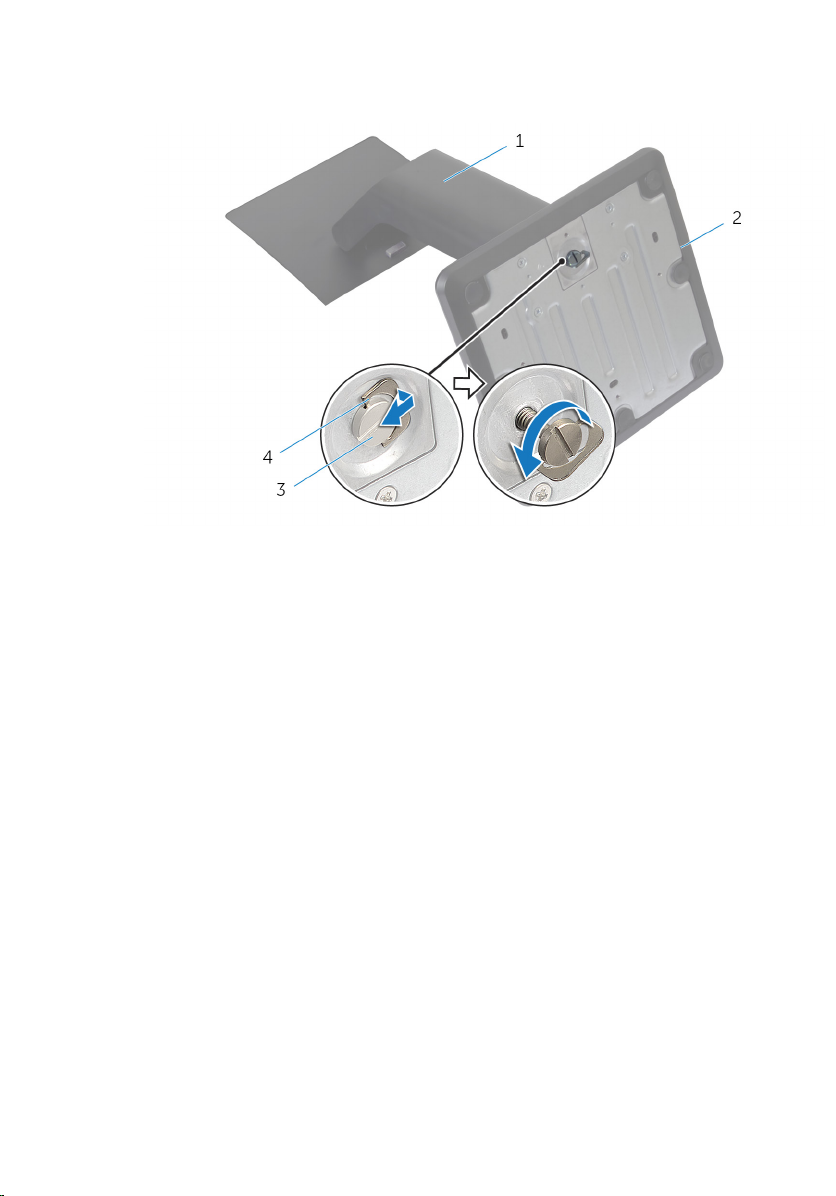
4 Using the screw handle, loosen the captive thumbscrew that secures the
stand base to the stand riser.
1 stand riser 2 stand base
3 captive thumbscrew 4 screw handle
18
Page 19
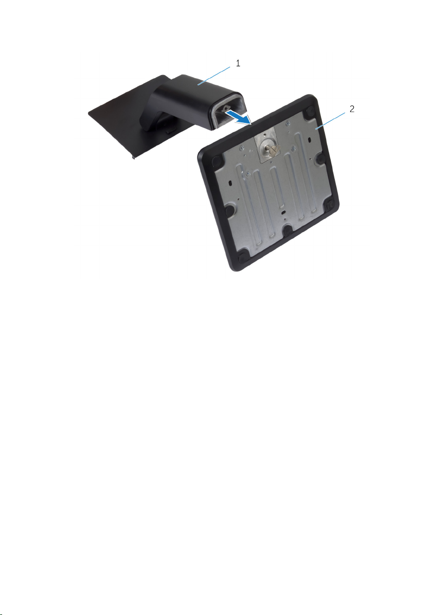
5 Slide the stand base off the stand riser.
1 stand riser 2 stand base
19
Page 20

Replacing the Stand Assembly
WARNING: Before working inside your computer, read the safety
information that shipped with your computer and follow the steps in
Before Working Inside Your Computer. After working inside your
computer, follow the instructions in After Working Inside Your
Computer. For more safety best practices, see the Regulatory
Compliance home page at dell.com/regulatory_compliance.
Procedure
1 Slide the tabs on the stand assembly into the slots on the back cover.
2 Lower the stand assembly to lock it into place.
If you have removed the stand base from the stand riser, follow the steps
below:
3 Align the captive thumbscrew on the stand base with the screw hole on
the stand riser and tighten it.
4 Fold the screw handle on the stand base.
20
Page 21
Removing the Back Cover
WARNING: Before working inside your computer, read the safety
information that shipped with your computer and follow the steps in
Before Working Inside Your Computer. After working inside your
computer, follow the instructions in After Working Inside Your
Computer. For more safety best practices, see the Regulatory
Compliance home page at dell.com/regulatory_compliance.
Prerequisites
Remove the stand assembly.
Procedure
CAUTION: Do not remove the computer cover unless you need to
install internal accessories for your computer.
1 Slide the release latches to the unlocked position indicated by a circle.
1 right release latch 2 left release latch
2 Using a plastic scribe, pry the back cover from the display bezel starting
from the optical drive area.
21
Page 22
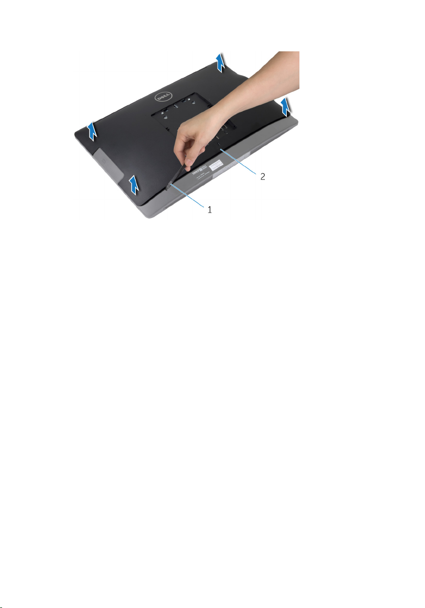
3 Lift the back cover off the computer.
1 plastic scribe 2 back cover
22
Page 23

Replacing the Back Cover
WARNING: Before working inside your computer, read the safety
information that shipped with your computer and follow the steps in
Before Working Inside Your Computer. After working inside your
computer, follow the instructions in After Working Inside Your
Computer. For more safety best practices, see the Regulatory
Compliance home page at dell.com/regulatory_compliance.
Procedure
1 Align the tabs on the back cover with the slots on the display bezel and
snap the back cover into place.
2 Slide the release latches to the locked position.
Post-requisites
Replace the stand assembly.
23
Page 24
Removing the Speaker Cover
WARNING: Before working inside your computer, read the safety
information that shipped with your computer and follow the steps in
Before Working Inside Your Computer. After working inside your
computer, follow the instructions in After Working Inside Your
Computer. For more safety best practices, see the Regulatory
Compliance home page at dell.com/regulatory_compliance.
Prerequisites
1 Remove the stand assembly.
2 Remove the back cover.
Procedure
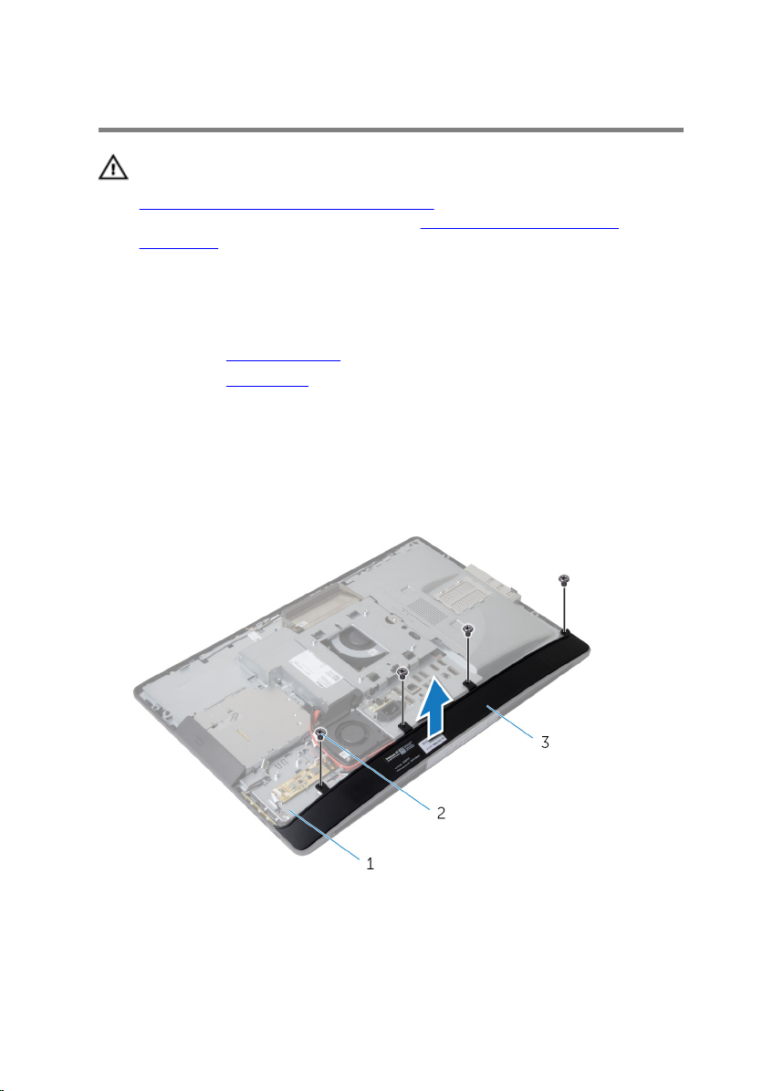
1 Remove the screws that secure the speaker cover to the display-panel
base.
2 Lift the speaker cover off the computer.
24
1 display-panel base 2 screws (4)
3 speaker cover
Page 25

Replacing the Speaker Cover
WARNING: Before working inside your computer, read the safety
information that shipped with your computer and follow the steps in
Before Working Inside Your Computer. After working inside your
computer, follow the instructions in After Working Inside Your
Computer. For more safety best practices, see the Regulatory
Compliance home page at dell.com/regulatory_compliance.
Procedure
1 Align the screw holes on the speaker cover with the screw holes on the
display-panel base.
2 Replace the screws that secure the speaker cover to the display-panel
base.
Post-requisites
1 Replace the back cover.
2 Replace the stand assembly.
25
Page 26

Removing the Speakers
WARNING: Before working inside your computer, read the safety
information that shipped with your computer and follow the steps in
Before Working Inside Your Computer. After working inside your
computer, follow the instructions in After Working Inside Your
Computer. For more safety best practices, see the Regulatory
Compliance home page at dell.com/regulatory_compliance.
Prerequisites
1 Remove the stand assembly.
2 Remove the back cover.
3 Remove the speaker cover.
Procedure
1 Disconnect the speaker cable from the system board.
2 Note the speaker-cable routing and remove the cable from the routing
guide.
3 Remove the screws that secure the speakers to the display-panel base.
26
Page 27
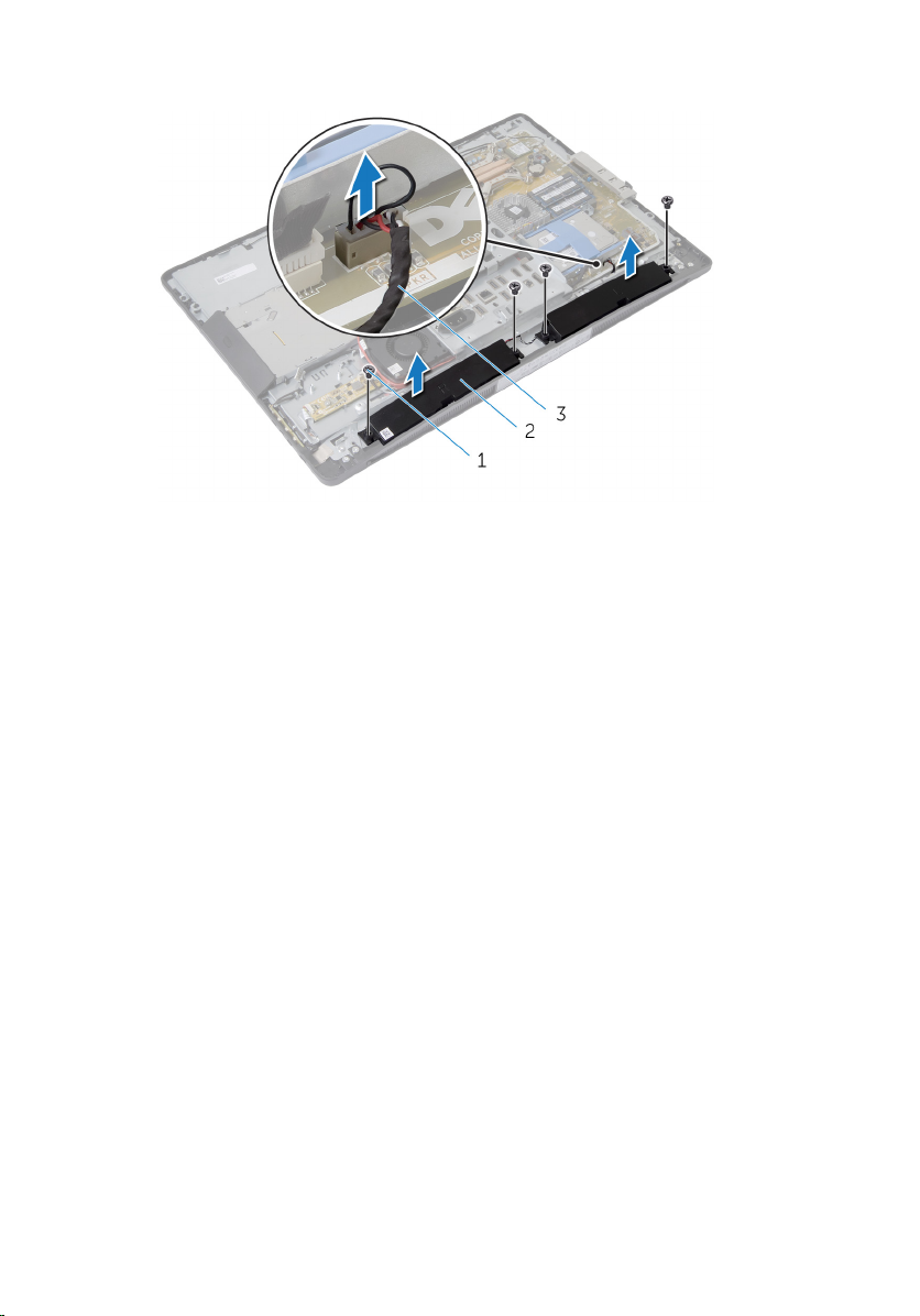
4 Lift the speakers off the display-panel base.
1 screws (4) 2 speakers (2)
3 speaker cable
27
Page 28

Replacing the Speakers
WARNING: Before working inside your computer, read the safety
information that shipped with your computer and follow the steps in
Before Working Inside Your Computer. After working inside your
computer, follow the instructions in After Working Inside Your
Computer. For more safety best practices, see the Regulatory
Compliance home page at dell.com/regulatory_compliance.
Procedure
1 Align the screw holes on the speakers with the screw holes on the
display-panel base.
2 Replace the screws that secure the speakers to the display-panel base.
3 Route the speaker cables through the routing guide on the display-panel
base.
4 Connect the speaker cable to the system board.
Post-requisites
1 Replace the speaker cover.
2 Replace the back cover.
3 Replace the stand assembly.
28
Page 29

Removing the Memory Module(s)
WARNING: Before working inside your computer, read the safety
information that shipped with your computer and follow the steps in
Before Working Inside Your Computer. After working inside your
computer, follow the instructions in After Working Inside Your
Computer. For more safety best practices, see the Regulatory
Compliance home page at dell.com/regulatory_compliance.
Prerequisites
1 Remove the stand assembly.
2 Remove the back cover.
29
Page 30
Procedure
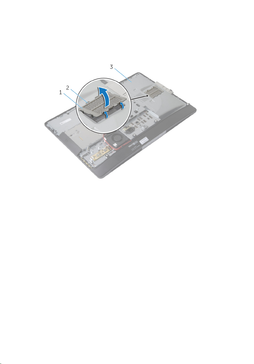
1 Using the tabs, pry the memory-module shield off the system-board
shield.
1 memory-module shield 2 tabs (6)
3 system-board shield
2 Use your fingertips to carefully spread apart the securing clips on each
end of the memory-module connector until the memory module pops
up.
30
Page 31

3 Remove the memory module from the memory-module connector.
1 memory-module connector 2 memory modules (2)
3 securing clips (4)
31
Page 32

Replacing the Memory Module(s)
WARNING: Before working inside your computer, read the safety
information that shipped with your computer and follow the steps in
Before Working Inside Your Computer. After working inside your
computer, follow the instructions in After Working Inside Your
Computer. For more safety best practices, see the Regulatory
Compliance home page at dell.com/regulatory_compliance.
32
Page 33

Procedure
1 Align the notch on the memory module with the tab on the memory-
module connector.
2 Insert the memory module into the memory-module connector, and
press the memory module down until it clicks into place.
NOTE: If you do not hear the click, remove the memory module
and reinstall it.
1 memory-module connector 2 memory modules (2)
3 tab 4 notch
5 securing clips (4)
33
Page 34

1 memory modules (2)
3 Slide the tabs on the memory-module shield under the tabs on the
system-board shield until the memory-module shield is fully secured.
Post-requisites
1 Replace the back cover.
2 Replace the stand assembly.
34
Page 35

Removing the System-Board Shield
WARNING: Before working inside your computer, read the safety
information that shipped with your computer and follow the steps in
Before Working Inside Your Computer. After working inside your
computer, follow the instructions in After Working Inside Your
Computer. For more safety best practices, see the Regulatory
Compliance home page at dell.com/regulatory_compliance.
Prerequisites
1 Remove the stand assembly.
2 Remove the back cover.
Procedure
1 Press the securing tab down and slide the system-board shield to release
it from the slots on the display-panel base.
2 Lift the system-board shield off the computer.
1 securing tab 2 system-board shield
35
Page 36

Replacing the System-Board Shield
WARNING: Before working inside your computer, read the safety
information that shipped with your computer and follow the steps in
Before Working Inside Your Computer. After working inside your
computer, follow the instructions in After Working Inside Your
Computer. For more safety best practices, see the Regulatory
Compliance home page at dell.com/regulatory_compliance.
Procedure
1 Align and place the system-board shield on the display-panel base.
2 Slide the tabs on the system-board shield into the slots on the display-
panel base until it snaps into place.
Post-requisites
1 Replace the back cover.
2 Replace the stand assembly.
36
Page 37

Removing the Hard Drive
WARNING: Before working inside your computer, read the safety
information that shipped with your computer and follow the steps in
Before Working Inside Your Computer. After working inside your
computer, follow the instructions in After Working Inside Your
Computer. For more safety best practices, see the Regulatory
Compliance home page at dell.com/regulatory_compliance.
CAUTION: Hard drives are fragile. Exercise care when handling the
hard drive.
CAUTION: To avoid data loss, do not remove the hard drive while the
computer is in Sleep or On state.
Prerequisites
1 Remove the stand assembly.
2 Remove the back cover.
3 Remove the system-board shield.
37
Page 38

Procedure
1 Press down on the hard-drive bracket and slide the hard-drive assembly
to release it from the hard-drive cage.
2 Lift the hard-drive assembly off the hard-drive cage.
1 hard-drive assembly 2 hard-drive bracket
3 hard-drive cage
38
Page 39

3 Gently pry the hard-drive bracket off the hard drive.
1 hard-drive 2 hard-drive bracket
4 Remove the screws that secure the hard-drive cage to the system board.
5 Lift the hard-drive cage off the system board.
1 hard-drive cage 2 screws (4)
39
Page 40

Replacing the Hard Drive
WARNING: Before working inside your computer, read the safety
information that shipped with your computer and follow the steps in
Before Working Inside Your Computer. After working inside your
computer, follow the instructions in After Working Inside Your
Computer. For more safety best practices, see the Regulatory
Compliance home page at dell.com/regulatory_compliance.
CAUTION: Hard drives are fragile. Exercise care when handling the
hard drive.
Procedure
1 Align the screw holes on the hard-drive cage with the screw holes on the
system board.
2 Replace the screws that secure the hard-drive cage to the system board.
3 Replace the hard-drive bracket to the hard drive.
4 Align the tabs on the hard-drive assembly with the slots on the hard-drive
cage.
5 Slide the hard-drive assembly into the hard-drive cage until it snaps into
position.
Post-requisites
1 Replace the system-board shield.
2 Replace the back cover.
3 Replace the stand assembly.
40
Page 41

Removing the VESA-Mount Bracket
WARNING: Before working inside your computer, read the safety
information that shipped with your computer and follow the steps in
Before Working Inside Your Computer. After working inside your
computer, follow the instructions in After Working Inside Your
Computer. For more safety best practices, see the Regulatory
Compliance home page at dell.com/regulatory_compliance.
Prerequisites
1 Remove the stand assembly.
2 Remove the back cover.
3 Remove the system-board shield.
Procedure
1 Remove the screws that secure the VESA-mount bracket to the display-
panel base.
2 Lift the VESA-mount bracket off the display-panel base.
1 VESA-mount bracket 2 screws (5)
41
Page 42

Replacing the VESA-Mount Bracket
WARNING: Before working inside your computer, read the safety
information that shipped with your computer and follow the steps in
Before Working Inside Your Computer. After working inside your
computer, follow the instructions in After Working Inside Your
Computer. For more safety best practices, see the Regulatory
Compliance home page at dell.com/regulatory_compliance.
Procedure
1 Align the screw holes on the VESA-mount bracket with the screw holes
on the display-panel base.
2 Replace the screws that secure the VESA-mount bracket to the display-
panel base.
Post-requisites
1 Replace the system-board shield.
2 Replace the back cover.
3 Replace the stand assembly.
42
Page 43

Removing the ControlButtons Board
WARNING: Before working inside your computer, read the safety
information that shipped with your computer and follow the steps in
Before Working Inside Your Computer. After working inside your
computer, follow the instructions in After Working Inside Your
Computer. For more safety best practices, see the Regulatory
Compliance home page at dell.com/regulatory_compliance.
Prerequisites
1 Remove the stand assembly.
2 Remove the back cover.
Procedure
1 Remove the screw that connects the ground cable to the display-panel
base.
2 Carefully pry and lift the control-buttons board off the display bezel.
43
Page 44

3 Disconnect the control-buttons board cable from the connector on the
control-buttons board.
1 ground cable 2 screw
3 control-buttons board cable 4 control-buttons board
44
Page 45

Replacing the Control-Buttons Board
WARNING: Before working inside your computer, read the safety
information that shipped with your computer and follow the steps in
Before Working Inside Your Computer. After working inside your
computer, follow the instructions in After Working Inside Your
Computer. For more safety best practices, see the Regulatory
Compliance home page at dell.com/regulatory_compliance.
Procedure
1 Connect the control-buttons board cable to the connector on the
control-buttons board.
2 Replace the control-buttons board into the slot on the display bezel.
3 Align the screw hole on the ground cable with the screw hole on the
display-panel base.
4 Replace the screw that secures the ground cable to the display-panel
base.
Post-requisites
1 Replace the back cover.
2 Replace the stand assembly.
45
Page 46

Removing the Converter Board
WARNING: Before working inside your computer, read the safety
information that shipped with your computer and follow the steps in
Before Working Inside Your Computer. After working inside your
computer, follow the instructions in After Working Inside Your
Computer. For more safety best practices, see the Regulatory
Compliance home page at dell.com/regulatory_compliance.
Prerequisites
1 Remove the stand assembly.
2 Remove the back cover.
Procedure
1 Disconnect the converter-board cable and display-backlight cable from
the connectors on the convertor board.
2 Remove the screws that secure the convertor board to the display-panel
base.
46
Page 47

3 Lift the converter board off the display-panel base.
1 screws (2) 2 display-backlight cable
3 converter board 4 converter-board cable
47
Page 48

Replacing the Converter Board
WARNING: Before working inside your computer, read the safety
information that shipped with your computer and follow the steps in
Before Working Inside Your Computer. After working inside your
computer, follow the instructions in After Working Inside Your
Computer. For more safety best practices, see the Regulatory
Compliance home page at dell.com/regulatory_compliance.
Procedure
1 Align the screw holes on the converter board with the screw holes on the
display-panel base.
2 Replace the screws that secure the converter board to the display-panel
base.
3 Connect the converter-board cable and display-backlight cable to the
connectors on the convertor board.
Post-requisites
1 Replace the back cover.
2 Replace the stand assembly.
48
Page 49

Removing the Power-Supply Diagnostic Board
WARNING: Before working inside your computer, read the safety
information that shipped with your computer and follow the steps in
Before Working Inside Your Computer. After working inside your
computer, follow the instructions in After Working Inside Your
Computer. For more safety best practices, see the Regulatory
Compliance home page at dell.com/regulatory_compliance.
Prerequisites
1 Remove the stand assembly.
2 Remove the back cover.
3 Remove the system-board shield.
4 Remove the VESA-mount bracket.
Procedure
1 Disconnect the power-supply diagnostic board cable from the power-
supply diagnostic board.
2 Remove the screw that secures the power-supply diagnostic board to the
I/O bracket.
49
Page 50

3 Lift the power-supply diagnostic board off the I/O bracket.
1 power-supply diagnostic
board
3 screw 4 I/O bracket
2 power-supply diagnostic
board cable
50
Page 51

Replacing the Power-Supply Diagnostic Board
WARNING: Before working inside your computer, read the safety
information that shipped with your computer and follow the steps in
Before Working Inside Your Computer. After working inside your
computer, follow the instructions in After Working Inside Your
Computer. For more safety best practices, see the Regulatory
Compliance home page at dell.com/regulatory_compliance.
Procedure
1 Connect the power-supply diagnostic board cable to the connector on
the power-supply diagnostic board.
2 Align the screw hole on the power-supply diagnostic board with the
screw hole on the I/O bracket.
3 Replace the screw that secures the power-supply diagnostic board to the
I/O bracket.
Post-requisites
1 Replace the VESA-mount bracket.
2 Replace the system-board shield.
3 Replace the back cover.
4 Replace the stand assembly.
51
Page 52

Removing the Microphone
WARNING: Before working inside your computer, read the safety
information that shipped with your computer and follow the steps in
Before Working Inside Your Computer. After working inside your
computer, follow the instructions in After Working Inside Your
Computer. For more safety best practices, see the Regulatory
Compliance home page at dell.com/regulatory_compliance.
Prerequisites
1 Remove the stand assembly.
2 Remove the back cover.
Procedure
1 Remove the screws that secure the microphone bracket to the
microphones.
2 Lift the microphone brackets off the display bezel.
3 Press the securing tabs to release the microphones and lift the
microphones out of their slots on the display bezel.
52
Page 53

4 Disconnect the microphone cables from the microphones.
1 right microphone 2 screws (2)
3 left microphone 4 securing tabs (2)
5 microphone brackets (2) 6 microphone cables (2)
53
Page 54

Replacing the Microphone
WARNING: Before working inside your computer, read the safety
information that shipped with your computer and follow the steps in
Before Working Inside Your Computer. After working inside your
computer, follow the instructions in After Working Inside Your
Computer. For more safety best practices, see the Regulatory
Compliance home page at dell.com/regulatory_compliance.
Procedure
1 Connect the microphone cables to the microphones.
2 Slide the microphones into the slots on the display bezel and make sure
the securing tabs are in position.
3 Align the screw holes on the microphone brackets with the screw holes
on the display bezel.
4 Replace the screws that secure the microphone brackets to the
microphones.
Post-requisites
1 Replace the back cover.
2 Replace the stand assembly.
54
Page 55

Removing the Wireless Card
WARNING: Before working inside your computer, read the safety
information that shipped with your computer and follow the steps in
Before Working Inside Your Computer. After working inside your
computer, follow the instructions in After Working Inside Your
Computer. For more safety best practices, see the Regulatory
Compliance home page at dell.com/regulatory_compliance.
Prerequisites
1 Remove the stand assembly.
2 Remove the back cover.
3 Remove the system-board shield.
Procedure
1 Disconnect the antenna cables from the connectors on the wireless card.
2 Remove the screw that secures the wireless card to the system board.
3 Slide and remove the wireless card out of the Mini Card slot on the
system board.
1 Mini Card slot 2 wireless card
3 antenna cables 4 screw
55
Page 56

Replacing the Wireless Card
WARNING: Before working inside your computer, read the safety
information that shipped with your computer and follow the steps in
Before Working Inside Your Computer. After working inside your
computer, follow the instructions in After Working Inside Your
Computer. For more safety best practices, see the Regulatory
Compliance home page at dell.com/regulatory_compliance.
Procedure
1 Align the notch on the wireless card with the tab on the Mini Card slot.
2 Slide the wireless card at an angle into the Mini Card slot.
3 Press the other end of the wireless card down and replace the screw that
secures the wireless card to the system board.
4 Connect the antenna cables to the wireless card.
The following table provides the antenna-cable color scheme for the
wireless card supported by your computer:
Connectors on the wireless card Antenna-cable color
Main (white triangle) White
Auxilary (black triangle) Black
Post-requisites
1 Replace the system-board shield.
2 Replace the back cover.
3 Replace the stand assembly.
56
Page 57

Removing the Coin-Cell Battery
WARNING: Before working inside your computer, read the safety
information that shipped with your computer and follow the steps in
Before Working Inside Your Computer. After working inside your
computer, follow the instructions in After Working Inside Your
Computer. For more safety best practices, see the Regulatory
Compliance home page at dell.com/regulatory_compliance.
CAUTION: Removing the coin-cell battery resets the BIOS settings to
default. It is recommended that you note the BIOS settings before
removing the coin-cell battery.
Prerequisites
1 Replace the stand assembly.
2 Replace the back cover.
3 Replace the system-board shield.
57
Page 58

Procedure
CAUTION: Removing the coin-cell battery resets the BIOS settings to
default. It is recommended that you note the BIOS settings before
removing the coin-cell battery.
1 Locate the coin-cell battery socket on the system board. For more
information, see System Board Components.
2 Using a plastic scribe, press the securing clip away from the coin-cell
battery until the coin-cell battery pops out.
58
1 plastic scribe 2 securing clip
3 coin-cell battery
Page 59

Replacing the Coin-Cell Battery
WARNING: Before working inside your computer, read the safety
information that shipped with your computer and follow the steps in
Before Working Inside Your Computer. After working inside your
computer, follow the instructions in After Working Inside Your
Computer. For more safety best practices, see the Regulatory
Compliance home page at dell.com/regulatory_compliance.
Procedure
With the positive-side facing up, insert the coin-cell battery into the battery
socket and press down the battery into place.
Post-requisites
1 Replace the system-board shield.
2 Replace the back cover.
3 Replace the stand assembly.
59
Page 60

Removing the I/O Bracket
WARNING: Before working inside your computer, read the safety
information that shipped with your computer and follow the steps in
Before Working Inside Your Computer. After working inside your
computer, follow the instructions in After Working Inside Your
Computer. For more safety best practices, see the Regulatory
Compliance home page at dell.com/regulatory_compliance.
Prerequisites
1 Remove the stand assembly.
2 Remove the back cover.
3 Remove the system-board shield.
4 Remove the VESA-mount bracket.
5 Remove the power-supply diagnostic board.
60
Page 61

Procedure
1 Remove the screws that secure the power port to the I/O bracket.
2 Remove the screws that secure the I/O bracket to the display-panel base.
1 power port screws (2) 2 power port
3 I/O bracket 4 I/O bracket screws (4)
3 Lift the I/O bracket slightly and slide the power port through the I/O
bracket.
61
Page 62

4 Lift the I/O bracket off the display-panel base.
1 power port 2 I/O bracket
62
Page 63

Replacing the I/O Bracket
WARNING: Before working inside your computer, read the safety
information that shipped with your computer and follow the steps in
Before Working Inside Your Computer. After working inside your
computer, follow the instructions in After Working Inside Your
Computer. For more safety best practices, see the Regulatory
Compliance home page at dell.com/regulatory_compliance.
Procedure
1 Slide the power port through the I/O bracket.
2 Align the screw holes on the I/O bracket with the screw holes on the
display-panel base.
3 Replace the screws that secure the I/O bracket to the display-panel base.
4 Align the screw holes on the power port with the screw holes on the I/O
bracket.
5 Replace the screws that secure the power port to the I/O bracket.
Post-requisites
1 Replace the power-supply diagnostic board.
2 Replace the VESA-mount bracket.
3 Replace the system-board shield.
4 Replace the back cover.
5 Replace the stand assembly.
63
Page 64

Removing the Optical Drive
WARNING: Before working inside your computer, read the safety
information that shipped with your computer and follow the steps in
Before Working Inside Your Computer. After working inside your
computer, follow the instructions in After Working Inside Your
Computer. For more safety best practices, see the Regulatory
Compliance home page at dell.com/regulatory_compliance.
Prerequisites
1 Remove the stand assembly.
2 Remove the back cover.
3 Remove the system-board shield.
4 Remove the VESA-mount bracket.
5 Remove the power-supply diagnostic board.
6 Remove the I/O bracket.
64
Page 65

Procedure
1 Press the securing tab down and slide the optical-drive assembly to
release it from the interposer.
1 optical-drive assembly 2 interposer
3 securing tab
2 Pivot the optical-drive bezel upward to release it from the optical-drive
assembly.
3 Remove the screws that secure the optical-drive bracket to the optical
drive.
65
Page 66

4 Remove the optical-drive bracket from the optical drive.
1 optical-drive bezel 2 optical drive
3 optical-drive bracket 4 screws (2)
5 Disconnect the power cable and data cable from the system board.
6 Remove the screws that secure the interposer to the display-panel base.
7 Remove the power cable and date cable from the routing guides on the
display-panel base.
66
Page 67

8 Lift the interposer off the display-panel base.
1 screws (2) 2 data cable
3 power cable
67
Page 68

Replacing the Optical Drive
WARNING: Before working inside your computer, read the safety
information that shipped with your computer and follow the steps in
Before Working Inside Your Computer. After working inside your
computer, follow the instructions in After Working Inside Your
Computer. For more safety best practices, see the Regulatory
Compliance home page at dell.com/regulatory_compliance.
Procedure
1 Route the power cable and data cable through the routing guides on the
display-panel base.
2 Align the screw holes on the interposer with the screw holes on the
display-panel base.
3 Replace the screws that secure the interposer to the display-panel base.
4 Connect the power and data cables to the system board.
5 Align the screw holes on the optical-drive bracket with the screw holes
on the optical drive.
6 Replace the screws that secure the optical-drive bracket to the optical
drive.
7 Align the tabs on the optical-drive bezel with the slots on the optical-
drive assembly and snap it into place.
8 Slide the optical-drive assembly into the optical-drive bay until it snaps
into position.
Post-requisites
1 Replace the I/O bracket.
2 Replace the power-supply diagnostic board.
3 Replace the VESA-mount bracket.
4 Replace the system-board shield.
5 Replace the back cover.
6 Replace the stand assembly.
68
Page 69

Removing the Power-Supply Fan
WARNING: Before working inside your computer, read the safety
information that shipped with your computer and follow the steps in
Before Working Inside Your Computer. After working inside your
computer, follow the instructions in After Working Inside Your
Computer. For more safety best practices, see the Regulatory
Compliance home page at dell.com/regulatory_compliance.
Prerequisites
1 Remove the stand assembly.
2 Remove the back cover.
3 Remove the system-board shield.
4 Remove the VESA-mount bracket.
5 Remove the power-supply diagnostic board.
6 Remove the I/O bracket.
69
Page 70

Procedure
1 Remove the screw that secures the power-supply fan bracket to the
display-panel base.
2 Lift the power-supply fan bracket off the display-panel base.
1 screw 2 power-supply fan bracket
3 Disconnect the power-supply fan cable from the power-supply unit.
70
Page 71

4 Remove the screws that secure the power-supply fan to the display-
panel base.
1 power-supply fan 2 screws (2)
3 power-supply fan cable
71
Page 72

Replacing the Power-Supply Fan
WARNING: Before working inside your computer, read the safety
information that shipped with your computer and follow the steps in
Before Working Inside Your Computer. After working inside your
computer, follow the instructions in After Working Inside Your
Computer. For more safety best practices, see the Regulatory
Compliance home page at dell.com/regulatory_compliance.
Procedure
1 Connect the power-supply fan cable to the power-supply unit.
2 Align the screw holes on the power-supply fan with the screw holes on
the display-panel base.
3 Replace the screws that secure the power-supply fan to the display-
panel base.
4 Align the screw holes on the power-supply fan bracket with the screw
holes on the display-panel base.
5 Replace the screw that secures the power-supply fan bracket to the
display-panel base.
Post-requisites
1 Replace the I/O bracket.
2 Replace the power-supply diagnostic board.
3 Replace the VESA-mount bracket.
4 Replace the system-board shield.
5 Replace the back cover.
6 Replace the stand assembly.
72
Page 73

Removing the Power-Supply Unit
WARNING: Before working inside your computer, read the safety
information that shipped with your computer and follow the steps in
Before Working Inside Your Computer. After working inside your
computer, follow the instructions in After Working Inside Your
Computer. For more safety best practices, see the Regulatory
Compliance home page at dell.com/regulatory_compliance.
Prerequisites
1 Remove the stand assembly.
2 Remove the back cover.
3 Remove the system-board shield.
4 Remove the VESA-mount bracket.
5 Remove the power-supply diagnostic board.
6 Remove the I/O bracket.
Procedure
1 Disconnect the main power cable, processor power cable and power-
supply fan cable from the system board.
2 Remove the main power cable, processor power cable and power-supply
fan cable from the routing guides on the display-panel base.
3 Remove the power-port cable from the routing guides on the display-
panel base.
73
Page 74

4 Disconnect the power-supply fan cable from the power-supply unit.
1 power-port cable 2 processor power cable
3 power-supply fan cable 4 main power cable
5 power-supply fan cable
5 Remove the screw that secures the power-supply unit to the display-
panel base.
74
Page 75

6 Slide and lift the power-supply unit to release it from the display-panel
base.
1 power-supply unit 2 screw
75
Page 76

Replacing the Power-Supply Unit
WARNING: Before working inside your computer, read the safety
information that shipped with your computer and follow the steps in
Before Working Inside Your Computer. After working inside your
computer, follow the instructions in After Working Inside Your
Computer. For more safety best practices, see the Regulatory
Compliance home page at dell.com/regulatory_compliance.
Procedure
1 Place the power-supply unit on the display-panel base and slide it into
position.
2 Align the screw hole and tabs on the power-supply unit with the screw
hole and tabs on the display-panel base.
3 Replace the screw that secures the power-supply unit to the display-
panel base.
4 Connect the power-supply fan cable to the power-supply unit.
5 Route the power-port cable through the routing guides on the display-
panel base.
6 Route the main power cable, processor power cable and power-supply
fan cable through the routing guides on the display-panel base.
7 Connect the main power cable, processor power cable and power-
supply fan cable to the system board.
Post-requisites
1 Replace the I/O bracket.
2 Replace the power-supply diagnostic board.
3 Replace the VESA-mount bracket.
4 Replace the system-board shield.
5 Replace the back cover.
6 Replace the stand assembly.
76
Page 77

Removing the Processor HeatSink
WARNING: Before working inside your computer, read the safety
information that shipped with your computer and follow the steps in
Before Working Inside Your Computer. After working inside your
computer, follow the instructions in After Working Inside Your
Computer. For more safety best practices, see the Regulatory
Compliance home page at dell.com/regulatory_compliance.
Prerequisites
1 Remove the stand assembly.
2 Remove the back cover.
3 Remove the system-board shield.
4 Remove the VESA-mount bracket.
Procedure
1 Loosen the captive screws that secure the processor heat-sink to the
system board.
2 Remove the screw that secures the processor heat-sink to the display-
panel base.
3 Peel off the Mylar from the processor heat-sink and fan.
77
Page 78

4 Lift the processor heat-sink off the system board.
1 Mylar 2 screw
3 processor heat-sink 4 captive screws (4)
78
Page 79

Replacing the Processor HeatSink
WARNING: Before working inside your computer, read the safety
information that shipped with your computer and follow the steps in
Before Working Inside Your Computer. After working inside your
computer, follow the instructions in After Working Inside Your
Computer. For more safety best practices, see the Regulatory
Compliance home page at dell.com/regulatory_compliance.
Procedure
NOTE: The original thermal grease can be reused, if the original
processor and heat sink are reinstalled together. If either the processor
or the heat sink is replaced, use the thermal pad provided in the kit to
ensure that thermal conductivity is achieved.
1 Align the captive screws on the heat sink with the screw holes on the
system board.
2 Tighten the captive screws that secure the processor heat-sink to the
system board.
3 Adhere the Mylar to the processor heat-sink and fan.
4 Replace the screw that secures the processor heat-sink to the display-
panel base.
Post-requisites
1 Replace the VESA-mount bracket.
2 Replace the system-board shield.
3 Replace the back cover.
4 Replace the stand assembly.
79
Page 80

Removing the Processor Fan
WARNING: Before working inside your computer, read the safety
information that shipped with your computer and follow the steps in
Before Working Inside Your Computer. After working inside your
computer, follow the instructions in After Working Inside Your
Computer. For more safety best practices, see the Regulatory
Compliance home page at dell.com/regulatory_compliance.
Prerequisites
1 Remove the stand assembly.
2 Remove the back cover.
3 Remove the system-board shield.
4 Remove the VESA-mount bracket.
Procedure
1 Disconnect the processor-fan cable from the system board.
2 Remove the screws that secure the processor fan to the display-panel
base.
3 Peel off the Mylar from the processor heat-sink and fan.
80
Page 81

4 Lift the processor fan off the display-panel base.
1 Mylar 2 processor fan
3 screws (3) 4 processor-fan cable
81
Page 82

Replacing the Processor Fan
WARNING: Before working inside your computer, read the safety
information that shipped with your computer and follow the steps in
Before Working Inside Your Computer. After working inside your
computer, follow the instructions in After Working Inside Your
Computer. For more safety best practices, see the Regulatory
Compliance home page at dell.com/regulatory_compliance.
Procedure
1 Align the screw holes on the processor fan with the screw holes on the
display-panel base.
2 Adhere the Mylar on the processor fan and the processor heat-sink.
3 Replace the screws that secure the processor fan to the display-panel
base.
4 Connect the processor-fan cable to the system board.
Post-requisites
1 Replace the VESA-mount bracket.
2 Replace the system-board shield.
3 Replace the back cover.
4 Replace the stand assembly.
82
Page 83

Removing the Processor
WARNING: Before working inside your computer, read the safety
information that shipped with your computer and follow the steps in
Before Working Inside Your Computer. After working inside your
computer, follow the instructions in After Working Inside Your
Computer. For more safety best practices, see the Regulatory
Compliance home page at dell.com/regulatory_compliance.
Prerequisites
1 Remove the stand assembly.
2 Remove the back cover.
3 Remove the system-board shield.
4 Remove the processor heat-sink.
5 Remove the processor fan.
Procedure
1 Press the release lever down on the processor cover and then pull it
outwards to release it from the tab that secures it.
2 Extend the release lever completely to open the processor cover.
83
Page 84

3 Gently lift the processor and remove it from the processor socket.
1 release lever 2 securing tab
3 processor cover 4 processor
84
Page 85

Replacing the Processor
WARNING: Before working inside your computer, read the safety
information that shipped with your computer and follow the steps in
Before Working Inside Your Computer. After working inside your
computer, follow the instructions in After Working Inside Your
Computer. For more safety best practices, see the Regulatory
Compliance home page at dell.com/regulatory_compliance.
CAUTION: If either the processor or the heat sink is replaced, use the
thermal grease provided in the kit to make sure that thermal
conductivity is achieved.
Procedure
NOTE: The original thermal grease can be reused, if the original
processor and heat sink are reinstalled together. If either the processor
or the heat sink is replaced, use the thermal pad provided in the kit to
ensure that thermal conductivity is achieved.
CAUTION: You must position the processor correctly in the processor
socket to avoid permanent damage to the processor.
1 If the release lever on the socket is not fully extended, move it to that
position.
2 Orient the alignment notches on the processor with the alignment tabs
on the processor socket.
3 Align the pin-1 corner on the processor with the pin-1 corner on the
processor socket, and then place the processor in the processor socket.
CAUTION: Ensure that the processor-cover notch is positioned
underneath the alignment post.
4 When the processor is fully seated in the socket, close the processor
cover.
85
Page 86

5 Pivot the release lever down and place it under the tab on the processor
cover.
1 processor pin-1 indicator 2 processor
3 alignment tabs (2) 4 alignment post
5 securing tab 6 processor cover
7 release lever
Post-requisites
1 Replace the processor fan.
2 Replace the processor heat-sink.
3 Replace the system-board shield.
4 Replace the back cover.
5 Replace the stand assembly.
86
Page 87

Removing the System Board
WARNING: Before working inside your computer, read the safety
information that shipped with your computer and follow the steps in
Before Working Inside Your Computer. After working inside your
computer, follow the instructions in After Working Inside Your
Computer. For more safety best practices, see the Regulatory
Compliance home page at dell.com/regulatory_compliance.
NOTE: Your computer’s Service Tag is stored in the system board. You
must enter the Service Tag in the system setup after you replace the
system board.
NOTE: Replacing the system board removes any changes you have
made to the BIOS using System Setup. Enter the Service Tag of your
computer in the BIOS and make the desired changes again after you
replace the system board.
NOTE: Before disconnecting the cables from the system board, note the
location of the connectors so that you can reconnect them correctly
after you replace the system board.
Prerequisites
1 Remove the stand assembly.
2 Remove the back cover.
3 Remove the memory module(s).
4 Remove the system-board shield.
5 Remove the VESA-mount bracket.
6 Remove the power-supply diagnostic board.
7 Remove the I/O bracket.
8 Remove the processor heat-sink.
9 Remove the processor fan.
10 Remove the processor.
11 Remove the hard drive.
12 Remove the wireless card.
13 Remove the coin-cell battery.
87
Page 88

Procedure
NOTE: Your computer’s Service Tag is stored in the system board. You
must enter the Service Tag in the BIOS after you replace the system
board.
88
Page 89

NOTE: Before disconnecting the cables from the system board, note the
location of the connectors and routing of the cables so that you can
reconnect them correctly after you replace the system board.
1 Disconnect all the cables connected to the system board.
1 processor power cable 2 camera cable
3 speaker cable 4 display cable
5 control-buttons board cable 6 converter-board cable
7 optical-drive power cable 8 video-card fan cable
9 optical-drive data cable 10 main-power cable
11 power-supply fan cable 12 touch-control board cable
2 Remove the screws that secure the system board to the display-panel
base.
89
Page 90

1 screws (12) 2 system board
3 Gently lift the system board at an angle and remove the side I/O bracket
off the system board.
4 Lift the system board off the display-panel bracket.
1 system board 2 side I/O bracket
90
Page 91

Replacing the System Board
WARNING: Before working inside your computer, read the safety
information that shipped with your computer and follow the steps in
Before Working Inside Your Computer. After working inside your
computer, follow the instructions in After Working Inside Your
Computer. For more safety best practices, see the Regulatory
Compliance home page at dell.com/regulatory_compliance.
NOTE: Your computer’s Service Tag is stored in the system board. You
must enter the Service Tag in the system setup after you replace the
system board.
Procedure
1 Replace the side I/O bracket on the system board.
2 Align the screw holes on the system board with the screw holes on the
display-panel base.
3 Replace the screws that secure the system board to the chassis.
4 Route and connect all the cables to the connectors on the system board.
Post-requisites
1 Replace the coin-cell battery.
2 Replace the wireless card.
3 Replace the hard drive.
4 Replace the processor.
5 Replace the processor fan.
6 Replace the processor heat-sink.
7 Replace the I/O bracket.
8 Replace the power-supply diagnostic board.
9 Replace the VESA-mount bracket.
10 Replace the system-board shield.
11 Replace the memory module(s).
12 Replace the back cover.
13 Replace the stand assembly.
91
Page 92

Entering the Service Tag in the BIOS
1 Turn on the computer.
2 Press <F2> when the DELL logo is displayed to enter the system setup
program.
3 Navigate to the main tab and enter the Service Tag in the Service Tag
Input field.
92
Page 93

Removing the Camera
WARNING: Before working inside your computer, read the safety
information that shipped with your computer and follow the steps in
Before Working Inside Your Computer. After working inside your
computer, follow the instructions in After Working Inside Your
Computer. For more safety best practices, see the Regulatory
Compliance home page at dell.com/regulatory_compliance.
Prerequisites
1 Remove the stand assembly.
2 Remove the back cover.
3 Remove the memory module(s).
4 Remove the system-board shield.
5 Remove the hard drive.
6 Remove the VESA-mount bracket.
7 Remove the control-buttons board.
8 Remove the converter board.
9 Remove the power-supply diagnostic board.
10 Remove the I/O bracket.
11 Remove the optical drive.
12 Remove the power-supply fan.
13 Remove the power-supply unit.
14 Remove the processor heat sink.
15 Remove the processor fan.
16 Remove the processor.
17 Remove the wireless card.
18 Remove the coin-cell battery.
19 Remove the system board.
20 Follow the procedure from step 1 to step 6 in "Removing the Display
Panel".
93
Page 94

Procedure
1 Remove the screw that secures the ground cable and the camera module
to the display bezel.
2 Move the ground cable away to access the camera module.
3 Carefully lift the camera module out of the display bezel.
4 Disconnect the camera cable from the camera module.
94
1 screw 2 camera module
3 ground cable 4 camera cable
Page 95

Replacing the Camera
WARNING: Before working inside your computer, read the safety
information that shipped with your computer and follow the steps in
Before Working Inside Your Computer. After working inside your
computer, follow the instructions in After Working Inside Your
Computer. For more safety best practices, see the Regulatory
Compliance home page at dell.com/regulatory_compliance.
Procedure
1 Connect the camera cable to the camera module.
2 Align the screw hole on the ground cable and the camera module with
the screw hole on the display bezel.
3 Replace the screw that secures the ground cable and the camera module
to the display bezel.
Post-requisites
1 Follow the procedure from step 11 to step 17 in "Replacing the Display
Panel".
2 Replace the system board.
3 Replace the coin-cell battery.
4 Replace the wireless card.
5 Replace the processor.
6 Replace the processor fan.
7 Replace the processor heat-sink.
8 Replace the power-supply unit.
9 Replace the power-supply fan.
10 Replace the optical drive.
11 Replace the I/O bracket.
12 Replace the power-supply diagnostic board.
13 Replace the converter board.
14 Replace the control buttons board.
15 Replace the VESA-mount bracket.
16 Replace the hard drive.
17 Replace the system-board shield.
95
Page 96

18 Replace the memory module(s).
19 Replace the back cover.
20 Replace the stand assembly.
96
Page 97

Removing the Antenna
WARNING: Before working inside your computer, read the safety
information that shipped with your computer and follow the steps in
Before Working Inside Your Computer. After working inside your
computer, follow the instructions in After Working Inside Your
Computer. For more safety best practices, see the Regulatory
Compliance home page at dell.com/regulatory_compliance.
Prerequisites
1 Remove the stand assembly.
2 Remove the back cover.
3 Remove the memory module(s).
4 Remove the system-board shield.
5 Remove the hard drive.
6 Remove the VESA-mount bracket.
7 Remove the control-buttons board.
8 Remove the converter board.
9 Remove the power-supply diagnostic board.
10 Remove the I/O bracket.
11 Remove the optical drive.
12 Remove the power-supply fan.
13 Remove the power-supply unit.
14 Remove the processor heat sink.
15 Remove the processor fan.
16 Remove the processor.
17 Remove the wireless card.
18 Remove the coin-cell battery.
19 Remove the system board.
Procedure
1 Peel the tape that secures the antenna modules to the display bezel.
2 Remove the screws that secure the antenna modules to the display bezel.
3 Note the antenna-cable routing and remove the antenna cables from the
routing guides on the display-panel base.
97
Page 98

4 Lift the antenna modules off the display bezel.
1 screws (2) 2 right antenna module
3 left antenna module 4 securing tape
98
Page 99

Replacing the Antenna
WARNING: Before working inside your computer, read the safety
information that shipped with your computer and follow the steps in
Before Working Inside Your Computer. After working inside your
computer, follow the instructions in After Working Inside Your
Computer. For more safety best practices, see the Regulatory
Compliance home page at dell.com/regulatory_compliance.
Procedure
1 Align the screw holes on the antenna modules with the screw holes on
the display bezel.
2 Replace the screws that secure the antenna modules to the display bezel.
3 Route the antenna cables through the routing guides on the display-
panel base.
4 Adhere the tape to secure the antenna modules to the display bezel.
Post-requisites
1 Replace the system board.
2 Replace the coin-cell battery.
3 Replace the wireless card.
4 Replace the processor.
5 Replace the processor fan.
6 Replace the processor heat-sink.
7 Replace the power-supply unit.
8 Replace the power-supply fan.
9 Replace the optical drive.
10 Replace the I/O bracket.
11 Replace the power-supply diagnostic board.
12 Replace the converter board.
13 Replace the control buttons board.
14 Replace the VESA-mount bracket.
15 Replace the hard drive.
16 Replace the system-board shield.
17 Replace the memory module(s).
99
Page 100

18 Replace the back cover.
19 Replace the stand assembly.
100
 Loading...