

Page 1

Dell Inspiron One 2020
Owner’s Manual
Computer model: Inspiron One 2020
Regulatory model: W06B
Regulatory type: W06B001
Page 2

Notes, Cautions, and Warnings
NOTE: A NOTE indicates important information that helps you make
better use of your computer.
CAUTION: A CAUTION indicates potential damage to hardware or loss
of data if instructions are not followed.
WARNING: A WARNING indicates a potential for property damage,
personal injury, or death.
____________________
© 2012 Dell Inc. All rights reserved.
Trademarks used in this text: Dell™, the DELL logo, and Inspiron™ are trademarks of
Dell Inc.; Microsoft
trademarks or registered trademarks of Microsoft corporation in the United States and/or
other countries; Intel
Corporation in the U.S. and other countries; Bluetooth
by Bluetooth SIG, Inc. and is used by Dell under license.
2012 - 10 Rev. A01
®
, Windows®, and the Windows start button logo are either
®
and Intel SpeedStep® are registered trademarks of Intel
®
is a registered trademark owned
Page 3

Contents
1 Technical Overview . . . . . . . . . . . . . . . . . . . . . . 7
Inside View of Your Computer . . . . . . . . . . . . . . . . 7
System Board Components. . . . . . . . . . . . . . . . . . 8
2 Before You Begin . . . . . . . . . . . . . . . . . . . . . . . 11
Turn Off Your Computer and Connected Devices . . 11
Safety Instructions . . . . . . . . . . . . . . . . . . . . . . . 11
Recommended Tools . . . . . . . . . . . . . . . . . . . . . 12
3 After Working Inside Your Computer . . . . . . . 13
4 Stand Cover . . . . . . . . . . . . . . . . . . . . . . . . . . . 15
Removing the Stand Cover . . . . . . . . . . . . . . . . . 15
Replacing the Stand Cover . . . . . . . . . . . . . . . . . 16
5Stand. . . . . . . . . . . . . . . . . . . . . . . . . . . . . . . . . 17
Removing the Stand. . . . . . . . . . . . . . . . . . . . . . 17
Replacing the Stand . . . . . . . . . . . . . . . . . . . . . . 18
6 Back Cover . . . . . . . . . . . . . . . . . . . . . . . . . . . . 19
Removing the Back Cover. . . . . . . . . . . . . . . . . . 19
Replacing the Back Cover . . . . . . . . . . . . . . . . . . 20
7 Hard Drive. . . . . . . . . . . . . . . . . . . . . . . . . . . . . 21
Removing the Hard Drive . . . . . . . . . . . . . . . . . . 21
Replacing the Hard Drive . . . . . . . . . . . . . . . . . . 23
8 Optical Drive. . . . . . . . . . . . . . . . . . . . . . . . . . . 25
Removing the Optical Drive. . . . . . . . . . . . . . . . . 25
Replacing the Optical Drive . . . . . . . . . . . . . . . . . 26
9 B-CAS Card (Japan Only). . . . . . . . . . . . . . . . . 27
Removing the B-CAS Card . . . . . . . . . . . . . . . . . 27
Replacing the B-CAS Card. . . . . . . . . . . . . . . . . . 28
Contents | 3
Page 4

10 Converter Board. . . . . . . . . . . . . . . . . . . . . . . . 29
Removing the Converter Board . . . . . . . . . . . . . . 29
Replacing the Converter Board . . . . . . . . . . . . . . 30
11 Memory Module(s) . . . . . . . . . . . . . . . . . . . . . . 31
Removing the Memory Module(s). . . . . . . . . . . . . 31
Replacing the Memory Module(s) . . . . . . . . . . . . . 33
12 System-Board Shield . . . . . . . . . . . . . . . . . . . . 35
Removing the System-Board Shield . . . . . . . . . . . 35
Replacing the System-Board Shield . . . . . . . . . . . 36
13 Antenna-In Connector . . . . . . . . . . . . . . . . . . 37
Removing the Antenna-In Connector . . . . . . . . . . 37
Replacing the Antenna-In Connector . . . . . . . . . . 38
14 Antenna Modules . . . . . . . . . . . . . . . . . . . . . . . 39
Removing the Antenna Modules. . . . . . . . . . . . . . 39
Replacing the Antenna Modules . . . . . . . . . . . . . . 40
15 TV-Tuner Card (Optional) . . . . . . . . . . . . . . . . 41
Removing the TV-Tuner Card. . . . . . . . . . . . . . . . 41
Replacing the TV-Tuner Card. . . . . . . . . . . . . . . . 43
16 Wireless Mini-Card (Optional). . . . . . . . . . . . . 45
Removing the Wireless Mini-Card. . . . . . . . . . . . . 45
Replacing the Wireless Mini-Card. . . . . . . . . . . . . 47
17 Coin-Cell Battery . . . . . . . . . . . . . . . . . . . . . . . 49
Removing the Coin-Cell Battery. . . . . . . . . . . . . . 49
Replacing the Coin-Cell Battery . . . . . . . . . . . . . . 50
18 Speakers . . . . . . . . . . . . . . . . . . . . . . . . . . . . . . 51
Removing the Speakers . . . . . . . . . . . . . . . . . . . 51
Replacing the Speakers. . . . . . . . . . . . . . . . . . . . 53
19 Fan . . . . . . . . . . . . . . . . . . . . . . . . . . . . . . . . . . . 55
Removing the Fan . . . . . . . . . . . . . . . . . . . . . . . 55
Replacing the Fan . . . . . . . . . . . . . . . . . . . . . . . 56
4 | Contents
Page 5

20 Power-Button Assembly . . . . . . . . . . . . . . . . . 57
Removing the Power-Button Assembly . . . . . . . . . 57
Replacing the Power-Button Assembly . . . . . . . . . 59
21 Processor Heat-Sink . . . . . . . . . . . . . . . . . . . . 61
Removing the Processor Heat-Sink. . . . . . . . . . . . 61
Replacing the Processor Heat-Sink . . . . . . . . . . . . 63
22 Processor . . . . . . . . . . . . . . . . . . . . . . . . . . . . . 65
Removing the Processor. . . . . . . . . . . . . . . . . . . 65
Replacing the Processor . . . . . . . . . . . . . . . . . . . 67
23 System Board . . . . . . . . . . . . . . . . . . . . . . . . . . 69
Removing the System Board . . . . . . . . . . . . . . . . 69
Replacing the System Board . . . . . . . . . . . . . . . . 71
Entering the Service Tag in the BIOS . . . . . . . . . . . 71
24 Display Panel . . . . . . . . . . . . . . . . . . . . . . . . . . 73
Removing the Display Panel . . . . . . . . . . . . . . . . 73
Replacing the Display Panel. . . . . . . . . . . . . . . . . 77
25 Infrared (IR) Receiver . . . . . . . . . . . . . . . . . . . . 79
Removing the Infrared Receiver . . . . . . . . . . . . . . 79
Replacing the Infrared Receiver . . . . . . . . . . . . . . 82
26 Middle Frame . . . . . . . . . . . . . . . . . . . . . . . . . . 83
Removing the Middle Frame . . . . . . . . . . . . . . . . 83
Replacing the Middle Frame . . . . . . . . . . . . . . . . 85
27 Camera Module . . . . . . . . . . . . . . . . . . . . . . . . 87
Removing the Camera Module. . . . . . . . . . . . . . . 87
Replacing the Camera Module . . . . . . . . . . . . . . . 89
28 Display Bezel . . . . . . . . . . . . . . . . . . . . . . . . . . 91
Removing the Display Bezel . . . . . . . . . . . . . . . . 91
Replacing the Display Bezel. . . . . . . . . . . . . . . . . 93
Contents | 5
Page 6

29 System Setup . . . . . . . . . . . . . . . . . . . . . . . . . . 95
Overview . . . . . . . . . . . . . . . . . . . . . . . . . . . . . 95
Clearing Forgotten Passwords . . . . . . . . . . . . . . 106
Clearing CMOS Settings . . . . . . . . . . . . . . . . . . 107
30 Flashing the BIOS . . . . . . . . . . . . . . . . . . . . . . 109
6 | Contents
Page 7
1
Technical Overview
WARNING:
shipped with your computer and follow the steps in "Before You Begin" on page 11.
For additional safety best practices information, see the Regulatory Compliance
Homepage at dell.com/regulatory_compliance.
Before working inside your computer, read the safety information that
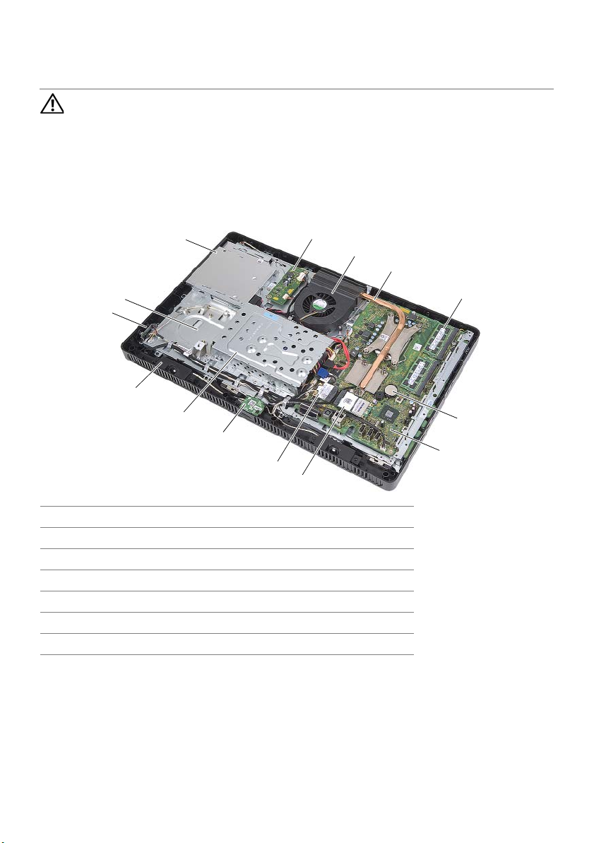
Inside View of Your Computer
3
2
1
14
13
12
11
4
5
6
7
8
9
10
1 power-button board 2 chassis
3 optical-drive assembly 4 converter board
5 fan 6 processor heat-sink
7 memory module(s) 8 coin-cell battery
9 system board 10 TV-tuner card (optional)
11 wireless Mini-Card 12 B-CAS card (Japan only)
13 hard-drive assembly 14 speakers (2)
Technical Overview | 7
Page 8
System Board Components
1
2
18
3
4
5
6
7
8
9
10 11 12 13
17
16
15
14
8 | Technical Overview
Page 9

1 processor socket 2 fan cable connector (FANC1)
3 camera cable connector (WEBCAM) 4 converter-board cable connector
(CONVERTER)
5 hard-drive and optical-drive
power cable connector (SATAP1)
7 hard-drive cable connector
(SATA_HDD)
9 IR-cable connector (IR_IN) 10 display-cable connector
11 wireless Mini-Card connector
(MINICARD WIFI)
13 speakers cable connector (SPEAKER) 14 password jumper (PWCLR1)
15 battery socket (BT1) 16 CMOS jumper (CMOCL1)
17 memory-module connector
(DIMMB1)
6 optical-drive cable connector
(SATA_ODD)
8 power-button and hard-drive activity
light cable connector (PWRCN1)
12 TV-tuner card connector
(MINICARD TV)
18 memory-module connector
(DIMMA1)
Technical Overview | 9
Page 10

10 | Technical Overview
Page 11

Before You Begin
2
Turn Off Your Computer and Connected Devices
CAUTION: To avoid losing data, save and close all open files and exit all
open programs before you turn off your computer.
1 Save and close all open files and exit all open programs.
2 Follow the instructions to shut down your computer based on the operating system
installed on your computer.
• Windows 8:
Move your mouse pointer to the upper-right or lower-right corner of the
screen to open the Charms sidebar, and then click Settings→ Power→
Shut down.
• Windows 7:
Click Start and click Shut down.
Microsoft Windows shuts down and then the computer turns off.
NOTE: If you are using a different operating system, see the documentation
of your operating system for shut-down instructions.
3 Disconnect your computer and all attached devices from their electrical outlets.
4 Disconnect all telephone cables, network cables, and attached devices from
your computer.
5 After the computer is unplugged, press and hold the power button for about
5 seconds to ground the system board.
Safety Instructions
Use the following safety guidelines to protect your computer from potential damage and
ensure your personal safety.
WARNING: Before working inside your computer, read the safety information
that shipped with your computer. For additional safety best practices
information, see the Regulatory Compliance Homepage at
dell.com/regulatory_compliance.
WARNING: Disconnect all power sources before opening the computer cover or
panels. After you finish working inside the computer, replace all covers, panels,
and screws before connecting to the power source.
CAUTION: To avoid damaging the computer, ensure that the work surface is
flat and clean.
CAUTION: To avoid damaging the components and cards, handle them by their
edges and avoid touching pins and contacts.
Before You Begin | 11
Page 12

CAUTION: Only a certified service technician is authorized to remove the
computer cover and access any of the components inside the computer.
See the safety instructions for complete information about safety precautions,
working inside your computer, and protecting against electrostatic discharge.
CAUTION: Before touching anything inside your computer, ground yourself by
touching an unpainted metal surface, such as the metal at the back of the
computer. While you work, periodically touch an unpainted metal surface to
dissipate static electricity, which could harm internal components.
CAUTION: When you disconnect a cable, pull on its connector or on its pull-tab,
not on the cable itself. Some cables have connectors with locking tabs or
thumb-screws that you must disengage before disconnecting the cable.
When disconnecting cables, keep them evenly aligned to avoid bending any
connector pins. When connecting cables, ensure that the connectors and ports
are correctly oriented and aligned.
CAUTION: To disconnect a network cable, first unplug the cable from your
computer and then unplug the cable from the network device.
Recommended Tools
The procedures in this document may require the following tools:
• Phillips screwdriver
• Hex nut driver
• Plastic scribe
12 | Before You Begin
Page 13

After Working Inside Your Computer
3
After you complete replacement procedures, ensure the following:
• Replace all screws and ensure that no stray screws remain inside your computer
• Place the computer in an upright position
• Connect any external devices, cables, cards, and any other part(s) you removed
before working on your computer
• Connect your computer and all attached devices to their electrical outlets
CAUTION: Before turning on your computer, replace all screws and ensure that
no stray screws remain inside the computer. Failure to do so may damage your
computer.
After Working Inside Your Computer | 13
Page 14

14 | After Working Inside Your Computer
Page 15
4
Stand Cover
WARNING:
shipped with your computer and follow the steps in "Before You Begin" on page 11.
For additional safety best practices information, see the Regulatory Compliance
Homepage at dell.com/regulatory_compliance.
Before working inside your computer, read the safety information that
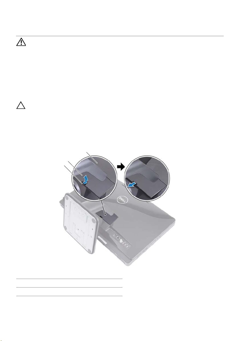
Removing the Stand Cover
Procedure
CAUTION: Before opening your computer, ensure that you place the computer
on a soft cloth or clean surface to avoid any scratches on the display.
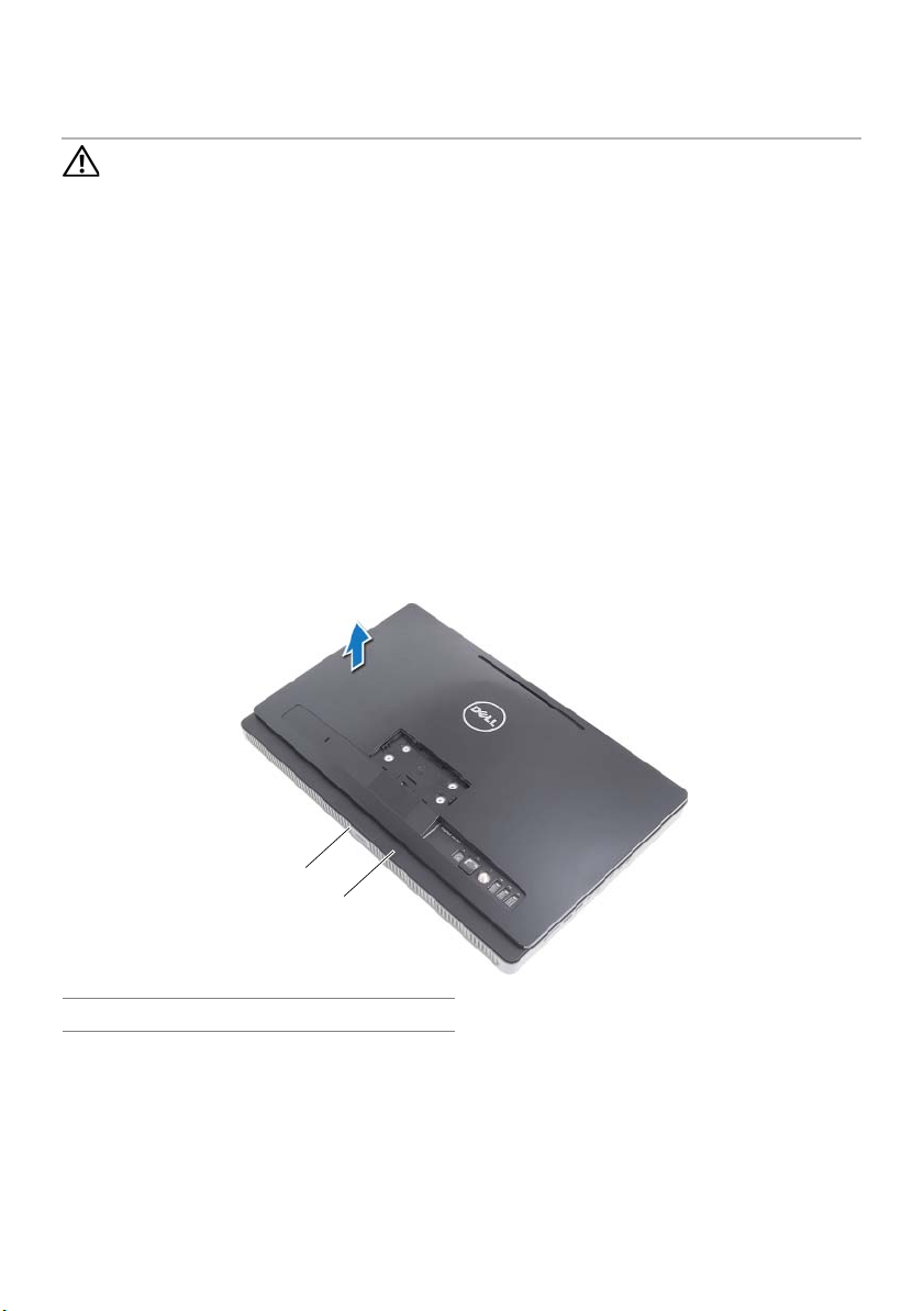
1 Place the computer face down on a flat surface.
2 Press the tab on the stand cover and lift the stand cover.
3 Slide and remove the stand cover away from the computer.
3
2
1
1 tab 2 stand cover
3 back cover
Stand Cover | 15
Page 16

Replacing the Stand Cover
Procedure
1 Slide the tabs on the stand cover into the slots on the back cover.
2 Snap the stand cover until it clicks into place.
3 Follow the instructions in "After Working Inside Your Computer" on page 13.
16 | Stand Cover
Page 17
5
Stand
WARNING:
shipped with your computer and follow the steps in "Before You Begin" on page 11.
For additional safety best practices information, see the Regulatory Compliance
Homepage at dell.com/regulatory_compliance.
Before working inside your computer, read the safety information that
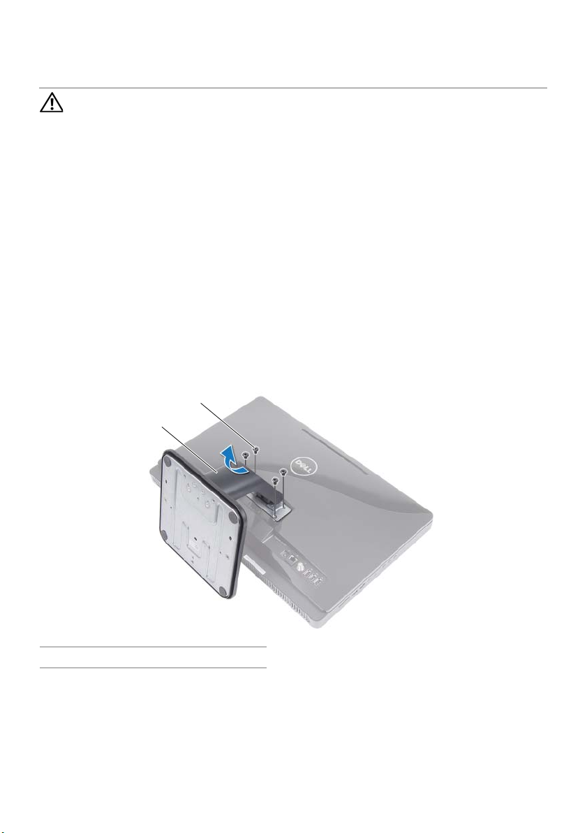
Removing the Stand
Prerequisites
Remove the stand cover. See "Removing the Stand Cover" on page 15.
Procedure
1 Remove the screws that secure the stand to the chassis.
2 Pivot the stand upward and slide it away from the computer.
2
1
1 stand 2 screws (4)
Stand | 17
Page 18

Replacing the Stand
Procedure
1 Slide the tabs on the stand into the slots on the back cover.
2 Replace the screws that secure the stand to the chassis.
Postrequisites
1 Replace the stand cover. See "Replacing the Stand Cover" on page 16.
2 Follow the instructions in "After Working Inside Your Computer" on page 13.
18 | Stand
Page 19
6
Back Cover
WARNING:
shipped with your computer and follow the steps in "Before You Begin" on page 11.
For additional safety best practices information, see the Regulatory Compliance
Homepage at dell.com/regulatory_compliance.
Before working inside your computer, read the safety information that
Removing the Back Cover
Prerequisites
1 Remove the stand cover. See "Removing the Stand Cover" on page 15.
2 Remove the stand. See "Removing the Stand" on page 17.
Procedure
1 Starting from above the optical drive, pry the back cover from the middle frame.
2 Lift the back cover off the computer.
1
2
1 middle frame 2 back cover
Back Cover | 19
Page 20

Replacing the Back Cover
Procedure
Align the tabs on the back cover with the tabs on the middle frame and snap the
back cover into place.
Postrequisites
1 Replace the stand. See "Replacing the Stand" on page 18.
2 Replace the stand cover. See "Replacing the Stand Cover" on page 16.
3 Follow the instructions in "After Working Inside Your Computer" on page 13.
20 | Back Cover
Page 21

7
Hard Drive
WARNING:
shipped with your computer and follow the steps in "Before You Begin" on page 11.
For additional safety best practices information, see the Regulatory Compliance
Homepage at dell.com/regulatory_compliance.
CAUTION: To avoid data loss, do not remove the hard drive while the computer is
On or in Sleep state.
CAUTION: Hard drives are extremely fragile. Exercise care when handling the
hard drive.
Before working inside your computer, read the safety information that
Removing the Hard Drive
Prerequisites
1 Remove the stand cover. See "Removing the Stand Cover" on page 15.
2 Remove the stand. See "Removing the Stand" on page 17.
3 Remove the back cover. See "Removing the Back Cover" on page 19.
Hard Drive | 21
Page 22
Procedure
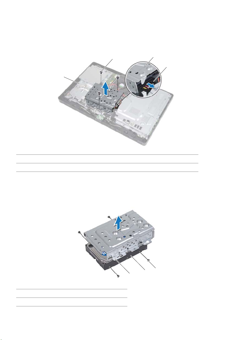
1 Remove the screws that secure the hard-drive assembly to the chassis.
2 Slide and lift the hard-drive assembly and then disconnect the power and data
cable from the connector on the hard drive.
2
1
1 chassis 2 screw (3)
3 hard-drive assembly 4 power and data cable
3 Remove the screws that secure the hard-drive cage to the hard drive.
4 Lift the hard-drive cage off the hard drive.
3
4
1 hard-drive cage 2 hard drive
3screws (4)
22 | Hard Drive
3
2
1
Page 23

Replacing the Hard Drive
Procedure
1 Align the screw holes on the hard-drive cage with the screw holes on the
hard drive.
2 Replace the screws that secure the hard-drive cage to the hard drive.
3 Connect the power and data cable to the connector on the hard-drive assembly.
4 Place the hard-drive assembly on the chassis and slide the hard-drive assembly
into place. Ensure that the slots on the hard-drive cage are secured under the tabs
on the chassis.
5 Replace the screws that secure the hard-drive assembly to the chassis.
Postrequisites
1 Replace the back cover. See "Replacing the Back Cover" on page 20.
2 Replace the stand. See "Replacing the Stand" on page 18.
3 Replace the stand cover. See "Replacing the Stand Cover" on page 16.
4 Follow the instructions in "After Working Inside Your Computer" on page 13.
Hard Drive | 23
Page 24

24 | Hard Drive
Page 25
8
Optical Drive
WARNING:
shipped with your computer and follow the steps in "Before You Begin" on page 11.
For additional safety best practices information, see the Regulatory Compliance
Homepage at dell.com/regulatory_compliance.
Before working inside your computer, read the safety information that
Removing the Optical Drive
Prerequisites
1 Remove the stand cover. See "Removing the Stand Cover" on page 15.
2 Remove the stand. See "Removing the Stand" on page 17.
3 Remove the back cover. See "Removing the Back Cover" on page 19.
Procedure
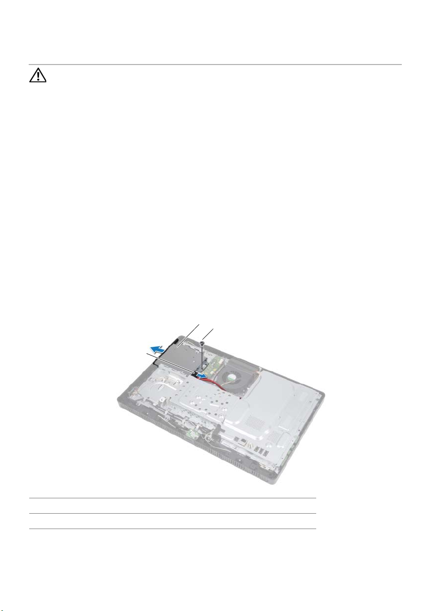
1 Disconnect the power and data cable from the connector on the
optical-drive assembly.
2 Remove the screw that secures the optical-drive assembly to the chassis.
3 Slide the optical-drive assembly out of the optical-drive bay.
2
3
1
1 power and data cable 2 optical-drive assembly
3screw
Optical Drive | 25
Page 26
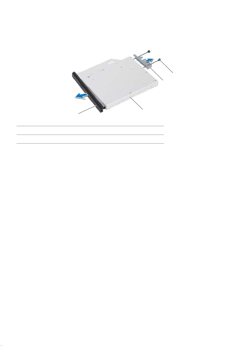
4 Carefully pry the optical-drive bezel and remove it from the optical-drive assembly.
5 Remove the screws that secure the optical-drive bracket to the optical drive.
6 Remove the optical-drive bracket.
4
3
1
1 optical-drive bezel 2 optical drive
3 optical-drive bracket 4 screws (2)
2
Replacing the Optical Drive
Procedure
1 Align the screw holes on the optical-drive bracket with the screw holes on the
optical drive.
2 Replace the screws that secure the optical-drive bracket to the optical drive.
3 Align the tabs on the optical-drive bezel with the slots on the optical-drive
assembly and snap the optical-drive bezel into place.
4 Slide the optical-drive assembly into the optical-drive bay until it is fully seated.
5 Replace the screw that secures the optical-drive assembly to the chassis.
6 Connect the power and data cable to the connector on the optical-drive assembly.
Postrequisites
1 Replace the back cover. See "Replacing the Back Cover" on page 20.
2 Replace the stand. See "Replacing the Stand" on page 18.
3 Replace the stand cover. See "Replacing the Stand Cover" on page 16.
4 Follow the instructions in "After Working Inside Your Computer" on page 13.
26 | Optical Drive
Page 27
9
B-CAS Card (Japan Only)
WARNING:
shipped with your computer and follow the steps in "Before You Begin" on page 11.
For additional safety best practices information, see the Regulatory Compliance
Homepage at dell.com/regulatory_compliance.
Before working inside your computer, read the safety information that
Removing the B-CAS Card
Prerequisites
1 Remove the stand cover. See "Removing the Stand Cover" on page 15.
2 Remove the stand. See "Removing the Stand" on page 17.
3 Remove the back cover. See "Removing the Back Cover" on page 19.
Procedure
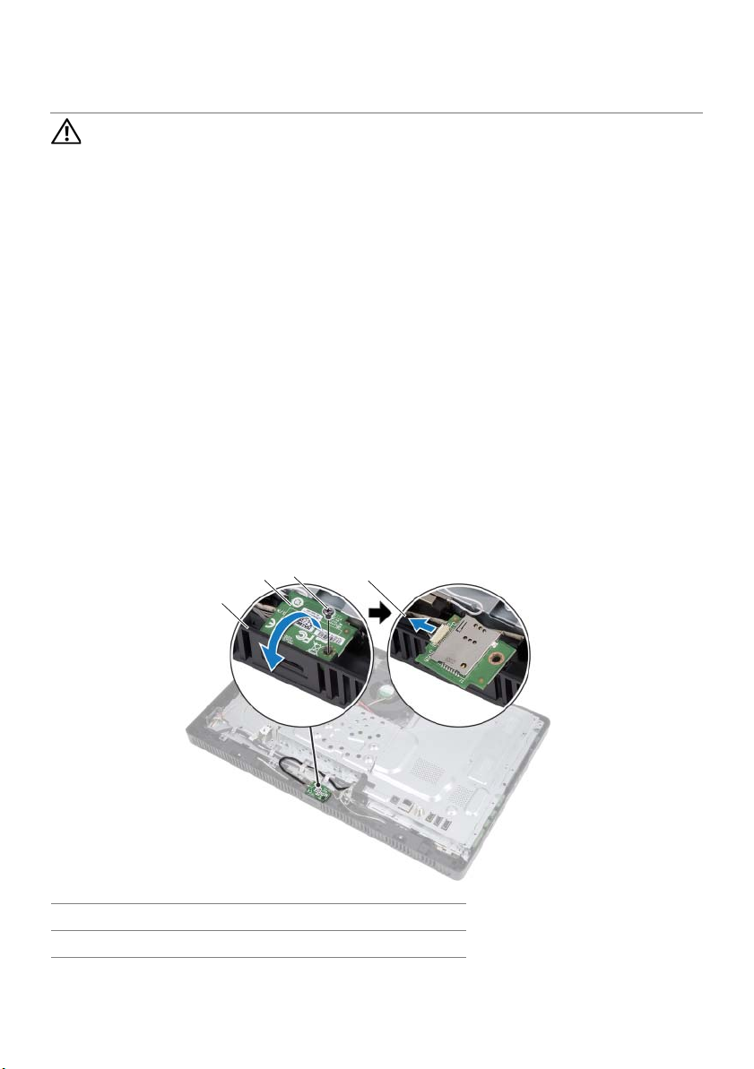
1 Remove the screw that secures the B-CAS card to the middle frame.
2 Turn the B-CAS card over.
3 Disconnect the B-CAS-card cable from the connector on the B-CAS card.
4 Lift the B-CAS card away from the computer.
3
2
1
4
1 middle frame 2 B-CAS card
3 screw 4 B-CAS-card cable
B-CAS Card (Japan Only) | 27
Page 28

Replacing the B-CAS Card
Procedure
1 Connect the B-CAS-card cable to the connector on the B-CAS card.
2 Turn the B-CAS card over.
3 Align the screw hole on the B-CAS card with the screw hole on the middle frame.
4 Replace the screw that secures the B-CAS card to the middle frame.
Postrequisites
1 Replace the back cover. See "Replacing the Back Cover" on page 20.
2 Replace the stand. See "Replacing the Stand" on page 18.
3 Replace the stand cover. See "Replacing the Stand Cover" on page 16.
4 Follow the instructions in "After Working Inside Your Computer" on page 13.
28 | B-CAS Card (Japan Only)
Page 29
10
Converter Board
WARNING:
shipped with your computer and follow the steps in "Before You Begin" on page 11.
For additional safety best practices information, see the Regulatory Compliance
Homepage at dell.com/regulatory_compliance.
Before working inside your computer, read the safety information that
Removing the Converter Board
Prerequisites
1 Remove the stand cover. See "Removing the Stand Cover" on page 15.
2 Remove the stand. See "Removing the Stand" on page 17.
3 Remove the back cover. See "Removing the Back Cover" on page 19.
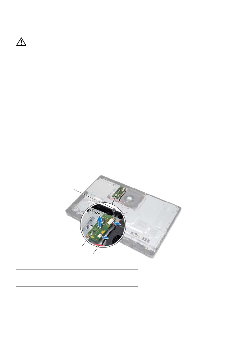
Procedure
1 Disconnect the cables from the connectors on the converter board.
2 Remove the screws that secure the converter board to the chassis.
3 Lift the converter board away from the chassis.
1
2
3
1 screws (2) 2 converter board
3cables (2)
Converter Board | 29
Page 30

Replacing the Converter Board
Procedure
1 Align the screw holes on the converter board with the screw holes on the chassis.
2 Replace the screws that secure the converter board to the chassis.
3 Connect the cables to the connectors on the converter board.
Postrequisites
1 Replace the back cover. See "Replacing the Back Cover" on page 20.
2 Replace the stand. See "Replacing the Stand" on page 18.
3 Replace the stand cover. See "Replacing the Stand Cover" on page 16.
4 Follow the instructions in "After Working Inside Your Computer" on page 13.
30 | Converter Board
Page 31

11
Memory Module(s)
WARNING:
shipped with your computer and follow the steps in "Before You Begin" on page 11.
For additional safety best practices information, see the Regulatory Compliance
Homepage at dell.com/regulatory_compliance.
Before working inside your computer, read the safety information that
Removing the Memory Module(s)
Prerequisites
1 Remove the stand cover. See "Removing the Stand Cover" on page 15.
2 Remove the stand. See "Removing the Stand" on page 17.
3 Remove the back cover. See "Removing the Back Cover" on page 19.
Procedure
1 Remove the screw that secures the memory-module shield to the
system-board shield.
2 Slide the memory-module shield toward the top of the computer, and lift it off the
system-board shield.
1
2
3
1 system-board shield 2 screw
3 memory-module shield
Memory Module(s) | 31
Page 32

3 Use your fingertips to carefully spread apart the securing clips on each end of the
memory-module connector until the memory module pops up.
4 Remove the memory module from the memory-module connector.
1
3
2
1 memory-module connector 2 securing clips (2)
3memory module
32 | Memory Module(s)
Page 33

Replacing the Memory Module(s)
Procedure
1 Align the notch on the memory module with the tab on the
memory-module connector.
2 Slide the memory module firmly into the connector at a 45-degree angle, and press
the memory module down until it clicks into place. If you do not hear the click,
remove the memory module and reinstall it.
NOTE: If the memory module is not installed properly, the computer may
not boot.
2
1
1tab 2notch
3 Insert the tabs on the memory-module shield into the slots on the
system-board shield and then slide the memory-module shield toward the bottom
of the computer. Ensure that the screw hole on the memory-module shield aligns
with the screw hole on the system-board shield.
4 Replace the screw that secures the memory-module shield to the
system-board shield.
Postrequisites
1 Replace the back cover. See "Replacing the Back Cover" on page 20.
2 Replace the stand. See "Replacing the Stand" on page 18.
3 Replace the stand cover. See "Replacing the Stand Cover" on page 16.
4 Follow the instructions in "After Working Inside Your Computer" on page 13.
Memory Module(s) | 33
Page 34

34 | Memory Module(s)
Page 35

12
System-Board Shield
WARNING:
shipped with your computer and follow the steps in "Before You Begin" on page 11.
For additional safety best practices information, see the Regulatory Compliance
Homepage at dell.com/regulatory_compliance.
Before working inside your computer, read the safety information that
Removing the System-Board Shield
Prerequisites
1 Remove the stand cover. See "Removing the Stand Cover" on page 15.
2 Remove the stand. See "Removing the Stand" on page 17.
3 Remove the back cover. See "Removing the Back Cover" on page 19.
Procedure
1 Remove the screws that secure the system-board shield to the chassis.
2 Carefully lift the system-board shield and turn it over.
1 screws (5) 2 system-board shield
2
1
System-Board Shield | 35
Page 36

3 Disconnect the antenna-in connector cable from the connector on the
TV-tuner card.
4 Remove the antenna-in connector. See "Removing the Antenna-In Connector" on
page 37.
3
2
1
1 system-board shield 2 antenna-in connector cable
3 TV-tuner card
Replacing the System-Board Shield
Procedure
1 Replace the antenna-in connector. See "Replacing the Antenna-In Connector" on
page 38.
2 Connect the antenna-in connector cable to the connector on the TV-tuner card.
3 Turn the system-board shield over and align the screw holes on the
system-board shield with the screw holes on the chassis.
4 Replace the screws that secure the system-board shield to the chassis.
Postrequisites
1 Replace the back cover. See "Replacing the Back Cover" on page 20.
2 Replace the stand. See "Replacing the Stand" on page 18.
3 Replace the stand cover. See "Replacing the Stand Cover" on page 16.
4 Follow the instructions in "After Working Inside Your Computer" on page 13.
36 | System-Board Shield
Page 37

13
Antenna-In Connector
WARNING:
shipped with your computer and follow the steps in "Before You Begin" on page 11.
For additional safety best practices information, see the Regulatory Compliance
Homepage at dell.com/regulatory_compliance.
Before working inside your computer, read the safety information that
Removing the Antenna-In Connector
Prerequisites
1 Remove the stand cover. See "Removing the Stand Cover" on page 15.
2 Remove the stand. See "Removing the Stand" on page 17.
3 Remove the back cover. See "Removing the Back Cover" on page 19.
4 Remove the system-board shield. See "Removing the System-Board Shield" on
page 35.
Procedure
1 Remove the hex nut that secures the antenna-in connector to the
system-board shield.
2 Slide the antenna-in connector through the slot on the system-board shield.
3 Remove the antenna-in connector along with its cable away from the
system-board shield.
1 antenna-in connector 2 hex nut
1
2
Antenna-In Connector | 37
Page 38

Replacing the Antenna-In Connector
Procedure
1 Slide the antenna-in connector into the slot on the system-board shield.
2 Replace the hex nut that secures the antenna-in connector to the
system-board shield.
Postrequisites
1 Replace the system-board shield. See "Replacing the System-Board Shield" on
page 36.
2 Replace the back cover. See "Replacing the Back Cover" on page 20.
3 Replace the stand. See "Replacing the Stand" on page 18.
4 Replace the stand cover. See "Replacing the Stand Cover" on page 16.
5 Follow the instructions in "After Working Inside Your Computer" on page 13.
38 | Antenna-In Connector
Page 39

14
Antenna Modules
WARNING:
shipped with your computer and follow the steps in "Before You Begin" on page 11.
For additional safety best practices information, see the Regulatory Compliance
Homepage at dell.com/regulatory_compliance.
Before working inside your computer, read the safety information that
Removing the Antenna Modules
Prerequisites
1 Remove the stand cover. See "Removing the Stand Cover" on page 15.
2 Remove the stand. See "Removing the Stand" on page 17.
3 Remove the back cover. See "Removing the Back Cover" on page 19.
4 Remove the system-board shield. See "Removing the System-Board Shield" on
page 35.
Procedure
1 Disconnect the antenna cables from the connectors on the wireless Mini-Card.
2 Make a note of the antenna cables routing and remove them from the
routing guides.
3 Peel the antenna modules from the chassis.
3
1
2
1 antenna cables (2) 2 antenna modules (2)
3 wireless Mini-Card
Antenna Modules | 39
Page 40

Replacing the Antenna Modules
Procedure
1 Adhere the antenna modules to the chassis.
2 Route the antenna cables through the routing guides.
3 Connect the antenna cables to the connectors on the wireless Mini-Card.
Postrequisites
1 Replace the system-board shield. See "Replacing the System-Board Shield" on
page 36.
2 Replace the back cover. See "Replacing the Back Cover" on page 20.
3 Replace the stand. See "Replacing the Stand" on page 18.
4 Replace the stand cover. See "Replacing the Stand Cover" on page 16.
5 Follow the instructions in "After Working Inside Your Computer" on page 13.
40 | Antenna Modules
Page 41

15
TV-Tuner Card (Optional)
WARNING:
shipped with your computer and follow the steps in "Before You Begin" on page 11.
For additional safety best practices information, see the Regulatory Compliance
Homepage at dell.com/regulatory_compliance.
NOTE: Dell does not guarantee compatibility or provide support for TV-tuner cards
from sources other than Dell.
If you ordered a TV-tuner card with your computer, the card is already installed.
Your computer supports one full-size Mini-Card slot for a TV-tuner card.
Before working inside your computer, read the safety information that
Removing the TV-Tuner Card
Prerequisites
1 Remove the stand cover. See "Removing the Stand Cover" on page 15.
2 Remove the stand. See "Removing the Stand" on page 17.
3 Remove the back cover. See "Removing the Back Cover" on page 19.
4 Remove the system-board shield. See "Removing the System-Board Shield" on
page 35.
TV-Tuner Card (Optional) | 41
Page 42

Procedure
1 Disconnect the TV-tuner-card cable from the connector on the TV-tuner card.
2 Remove the screw that secures the TV-tuner card to the system-board connector.
3 Lift the TV-tuner card away from the system-board connector.
1
2
3
1 TV-tuner-card cable 2 screw
3 TV tuner card
CAUTION: When the TV-tuner card is not in the computer, store it in protective
antistatic packaging. See "Protecting Against Electrostatic Discharge" in the
safety instructions that shipped with your computer.
42 | TV-Tuner Card (Optional)
Page 43

Replacing the TV-Tuner Card
Procedure
CAUTION: To avoid damage to the TV-tuner card, ensure that there are no cables
under the TV-tuner card.
1 Align the notch on the TV-tuner card with the tab on the system-board connector.
2 Insert the TV-tuner card at a 45-degree angle into the system-board connector.
3 Press the other end of the TV-tuner card down and replace the screw that secures
the TV-tuner card to the system-board connector.
4 Connect the TV-tuner-card cable to the connector on the TV-tuner card.
Postrequisites
1 Replace the system-board shield. See "Replacing the System-Board Shield" on
page 36.
2 Replace the back cover. See "Replacing the Back Cover" on page 20.
3 Replace the stand. See "Replacing the Stand" on page 18.
4 Replace the stand cover. See "Replacing the Stand Cover" on page 16.
5 Follow the instructions in "After Working Inside Your Computer" on page 13.
TV-Tuner Card (Optional) | 43
Page 44

44 | TV-Tuner Card (Optional)
Page 45

16
Wireless Mini-Card (Optional)
WARNING:
shipped with your computer and follow the steps in "Before You Begin" on page 11.
For additional safety best practices information, see the Regulatory Compliance
Homepage at dell.com/regulatory_compliance.
NOTE: Dell does not guarantee compatibility or provide support for Mini-Cards
from sources other than Dell.
If you ordered a wireless Mini-Card with your computer, the card is already installed.
Your computer supports one half-size Mini-Card slot for Wireless Local Area Network
(WLAN) + Bluetooth combo card and Wi-Fi.
Before working inside your computer, read the safety information that
Removing the Wireless Mini-Card
Prerequisites
1 Remove the stand cover. See "Removing the Stand Cover" on page 15.
2 Remove the stand. See "Removing the Stand" on page 17.
3 Remove the back cover. See "Removing the Back Cover" on page 19.
4 Remove the system-board shield. See "Removing the System-Board Shield" on
page 35.
Wireless Mini-Card (Optional) | 45
Page 46

Procedure
1 Disconnect the antenna cable(s) from the Mini-Card.
2 Remove the screw that secures the Mini-Card to the system-board connector.
1
2
3
1 screw 2 Mini-Card
3 antenna cables (2)
3 Lift the Mini-Card away from the system-board connector.
CAUTION: When the Mini-Card is not in the computer, store it in protective
antistatic packaging. See "Protecting Against Electrostatic Discharge" in the
safety instructions that shipped with your computer.
46 | Wireless Mini-Card (Optional)
Page 47

Replacing the Wireless Mini-Card
Procedure
CAUTION: The connectors are keyed to ensure correct insertion. Use of excessive
force may damage the connectors.
CAUTION: To avoid damage to the Mini-Card, ensure that there are no cables
under the Mini-Card.
1 Align the notch on the Mini-Card with the tab on the system-board connector.
2 Insert the Mini-Card at a 45-degree angle into the system-board connector.
3 Press the other end of the Mini-Card down and replace the screw that secures the
Mini-Card to the system-board connector.
4 Connect the appropriate antenna cables to the Mini-Card you are installing.
The Mini-Card has two triangles (black and white) marked on the label:
• Connect the black cable to the connector marked with a black triangle.
• Connect the white cable to the connector marked with a white triangle.
Postrequisites
1 Replace the system-board shield. See "Replacing the System-Board Shield" on
page 36.
2 Replace the back cover. See "Replacing the Back Cover" on page 20.
3 Replace the stand. See "Replacing the Stand" on page 18.
4 Replace the stand cover. See "Replacing the Stand Cover" on page 16.
5 Follow the instructions in "After Working Inside Your Computer" on page 13.
Wireless Mini-Card (Optional) | 47
Page 48

48 | Wireless Mini-Card (Optional)
Page 49

17
Coin-Cell Battery
WARNING:
shipped with your computer and follow the steps in "Before You Begin" on page 11.
For additional safety best practices information, see the Regulatory Compliance
Homepage at dell.com/regulatory_compliance.
WARNING: A new battery can explode if it is incorrectly installed. Replace the
battery only with the same or equivalent type recommended by the
manufacturer. Discard used batteries according to the
manufacturer’s instructions.
Before working inside your computer, read the safety information that
Removing the Coin-Cell Battery
Prerequisites
1 Remove the stand cover. See "Removing the Stand Cover" on page 15.
2 Remove the stand. See "Removing the Stand" on page 17.
3 Remove the back cover. See "Removing the Back Cover" on page 19.
4 Remove the system-board shield. See "Removing the System-Board Shield" on
page 35.
Procedure
1 Locate the battery socket on the system board. See "System Board Components"
on page 8.
2 Press the battery-release lever away from the battery until the battery pops up.
3 Lift the battery away from the battery socket.
2
1
1 coin-cell battery 2 battery-release lever
3 + side of the coin-cell battery
3
Coin-Cell Battery | 49
Page 50

Replacing the Coin-Cell Battery
Procedure
Insert the new battery (CR2032) into the battery socket with the side labeled + facing up,
and press the battery into place.
Postrequisites
1 Replace the system-board shield. See "Replacing the System-Board Shield" on
page 36.
2 Replace the back cover. See "Replacing the Back Cover" on page 20.
3 Replace the stand. See "Replacing the Stand" on page 18.
4 Replace the stand cover. See "Replacing the Stand Cover" on page 16.
5 Follow the instructions in "After Working Inside Your Computer" on page 13.
50 | Coin-Cell Battery
Page 51

18
Speakers
WARNING:
shipped with your computer and follow the steps in "Before You Begin" on page 11.
For additional safety best practices information, see the Regulatory Compliance
Homepage at dell.com/regulatory_compliance.
Before working inside your computer, read the safety information that
Removing the Speakers
Prerequisites
1 Remove the stand cover. See "Removing the Stand Cover" on page 15.
2 Remove the stand. See "Removing the Stand" on page 17.
3 Remove the back cover. See "Removing the Back Cover" on page 19.
4 Remove the B-CAS card. See "Removing the B-CAS Card" on page 27.
5 Remove the system-board shield. See "Removing the System-Board Shield" on
page 35.
Speakers | 51
Page 52

Procedure
1 Disconnect the speakers cable from the connector (SPEAKER) on the system board.
2 Make note of the speakers cable routing and remove the cable from the
routing guides.
3 Remove the screws that secure the speakers to the middle frame.
4 Lift the speakers along with the cable off the middle frame.
4
1
2
3
1 screws (4) 2 speakers (2)
3 middle frame 4 speakers cable
52 | Speakers
Page 53

Replacing the Speakers
Procedure
1 Align the screw holes on the speakers with the screw holes on the middle frame.
2 Replace the screws that secure the speakers to the middle frame.
3 Route the speakers cable through the routing guides.
4 Connect the speakers cable to the connector (SPEAKER) on the system board.
Postrequisites
1 Replace the system-board shield. See "Replacing the System-Board Shield" on
page 36.
2 Replace the B-CAS card. See "Replacing the B-CAS Card" on page 28.
3 Replace the back cover. See "Replacing the Back Cover" on page 20.
4 Replace the stand. See "Replacing the Stand" on page 18.
5 Replace the stand cover. See "Replacing the Stand Cover" on page 16.
6 Follow the instructions in "After Working Inside Your Computer" on page 13.
Speakers | 53
Page 54

54 | Speakers
Page 55

19
Fan
WARNING:
shipped with your computer and follow the steps in "Before You Begin" on page 11.
For additional safety best practices information, see the Regulatory Compliance
Homepage at dell.com/regulatory_compliance.
Before working inside your computer, read the safety information that
Removing the Fan
Prerequisites
1 Remove the stand cover. See "Removing the Stand Cover" on page 15.
2 Remove the stand. See "Removing the Stand" on page 17.
3 Remove the back cover. See "Removing the Back Cover" on page 19.
4 Remove the system-board shield. See "Removing the System-Board Shield" on
page 35.
Fan | 55
Page 56

Procedure
1 Disconnect the fan cable from the connector (FANC1) on the system board.
2 Remove the fan cable from the routing guide on the fan.
3 Remove the screws that secure the fan to the chassis.
4 Lift the fan along with its cable away from the chassis.
1
3
2
1 screws (2) 2 fan
3 fan cable
Replacing the Fan
Procedure
1 Align the screw holes on the fan with the screw holes on the chassis.
2 Replace the screws that secure the fan to the chassis.
3 Route the fan cable through the routing guide on the fan.
4 Connect the fan cable to the connector (FANC1) on the system board.
Postrequisites
1 Replace the system-board shield. See "Replacing the System-Board Shield" on
page 36.
2 Replace the back cover. See "Replacing the Back Cover" on page 20.
3 Replace the stand. See "Replacing the Stand" on page 18.
4 Replace the stand cover. See "Replacing the Stand Cover" on page 16.
5 Follow the instructions in "After Working Inside Your Computer" on page 13.
56 | Fan
Page 57

20
Power-Button Assembly
WARNING:
shipped with your computer and follow the steps in "Before You Begin" on page 11.
For additional safety best practices information, see the Regulatory Compliance
Homepage at dell.com/regulatory_compliance.
Before working inside your computer, read the safety information that
Removing the Power-Button Assembly
Prerequisites
1 Remove the stand cover. See "Removing the Stand Cover" on page 15.
2 Remove the stand. See "Removing the Stand" on page 17.
3 Remove the back cover. See "Removing the Back Cover" on page 19.
4 Remove the system-board shield. See "Removing the System-Board Shield" on
page 35.
Power-Button Assembly | 57
Page 58

Procedure
1 Disconnect the power-button and hard-drive activity light cable from the
connector (PWRCN1) on the system board.
2 Make a note of the power-button and hard-drive activity light cable routing and
remove it from the routing guides.
3 Remove the screw that secures the power-button assembly to the middle frame.
4 Slide the power-button assembly toward the top of the computer and then lift it
away from the middle frame.
1
1 screw 2 power-button assembly
3 power-button and
hard-drive activity light cable
2
3
58 | Power-Button Assembly
Page 59

Replacing the Power-Button Assembly
Procedure
1 Place the power-button assembly on the middle frame and then slide it toward the
bottom of the computer. Ensure that the slot on the power-button assembly is
secured under the tab on the middle frame.
2 Align the screw hole on the power-button assembly with the screw hole on the
middle frame.
3 Replace the screw that secures the power-button assembly to the middle frame.
4 Route the power-button and hard-drive activity light cable through the
routing guides.
5 Connect the power-button and hard-drive activity light cable to the connector
(PWRCN1) on the system board.
Postrequisites
1 Replace the system-board shield. See "Replacing the System-Board Shield" on
page 36.
2 Replace the back cover. See "Replacing the Back Cover" on page 20.
3 Replace the stand. See "Replacing the Stand" on page 18.
4 Replace the stand cover. See "Replacing the Stand Cover" on page 16.
5 Follow the instructions in "After Working Inside Your Computer" on page 13.
Power-Button Assembly | 59
Page 60

60 | Power-Button Assembly
Page 61

21
Processor Heat-Sink
WARNING:
shipped with your computer and follow the steps in "Before You Begin" on page 11.
For additional safety best practices information, see the Regulatory Compliance
Homepage at dell.com/regulatory_compliance.
WARNING: The heat sink may be very hot during normal operation. Ensure that it
has had sufficient time to cool before you touch it.
Before working inside your computer, read the safety information that
Removing the Processor Heat-Sink
CAUTION: To ensure maximum cooling for the processor, do not touch the heat
transfer areas on the processor heat-sink. The oils in your skin can reduce the
heat transfer capability of the thermal grease.
Prerequisites
1 Remove the stand cover. See "Removing the Stand Cover" on page 15.
2 Remove the stand. See "Removing the Stand" on page 17.
3 Remove the back cover. See "Removing the Back Cover" on page 19.
4 Remove the system-board shield. See "Removing the System-Board Shield" on
page 35.
Processor Heat-Sink | 61
Page 62

Procedure
1 In sequential order (indicated on the processor heat-sink), loosen the
captive screws that secure the processor heat-sink to the system board.
2 Carefully lift the processor heat-sink away from the system board.
NOTE: The appearance of the processor heat-sink may vary based on your
computer model.
1
2
1 processor heat-sink 2 captive screws (7)
62 | Processor Heat-Sink
Page 63

Replacing the Processor Heat-Sink
CAUTION: Incorrect alignment of the processor heat-sink can cause damage to
the system board and processor.
Procedure
1 Clean the thermal grease from the bottom of the processor heat-sink and
reapply it.
NOTE: The original thermal grease can be reused if the original processor and
processor heat-sink are reinstalled together. If either the processor or the
processor heat-sink is replaced, use the thermal grease provided in the kit to
ensure that thermal conductivity is achieved.
2 Align the captive screws on the processor heat-sink with the screw holes on the
system board.
3 In sequential order (indicated on the processor heat-sink), tighten the
captive screws that secure the processor heat-sink to the system board.
Postrequisites
1 Replace the system-board shield. See "Replacing the System-Board Shield" on
page 36.
2 Replace the back cover. See "Replacing the Back Cover" on page 20.
3 Replace the stand. See "Replacing the Stand" on page 18.
4 Replace the stand cover. See "Replacing the Stand Cover" on page 16.
5 Follow the instructions in "After Working Inside Your Computer" on page 13.
Processor Heat-Sink | 63
Page 64

64 | Processor Heat-Sink
Page 65

22
Processor
WARNING:
shipped with your computer and follow the steps in "Before You Begin" on page 11.
For additional safety best practices information, see the Regulatory Compliance
Homepage at dell.com/regulatory_compliance.
Before working inside your computer, read the safety information that
Removing the Processor
Prerequisites
1 Remove the stand cover. See "Removing the Stand Cover" on page 15.
2 Remove the stand. See "Removing the Stand" on page 17.
3 Remove the back cover. See "Removing the Back Cover" on page 19.
4 Remove the system-board shield. See "Removing the System-Board Shield" on
page 35.
5 Remove the processor heat-sink. See "Removing the Processor Heat-Sink" on
page 61.
Processor | 65
Page 66

Procedure
1 Press the release lever down on the processor cover and then pull it outward to
release it from the tab that secures it.
2 Extend the release lever completely to open the processor cover.
Leave the release lever extended in the release position so that the socket is ready
for the new processor.
3 Gently lift the processor to remove it from the socket.
1
1release lever 2tab
3 processor cover 4 socket
5processor
3
2
5
4
66 | Processor
Page 67

Replacing the Processor
Procedure
1 Unpack the new processor, being careful not to touch the underside of
the processor.
CAUTION: Ground yourself by touching an unpainted metal surface.
2 If the release lever on the socket is not fully extended, move it to that position.
CAUTION: You must position the processor correctly in the processor socket to
avoid permanent damage to the processor.
3 Orient the alignment notches on the processor with the alignment tabs on
the socket.
4 Align the pin-1 corners of the processor and socket.
CAUTION: Ensure that the processor cover notch is positioned underneath the
alignment post.
5 When the processor is fully seated in the socket, close the processor cover.
6 Pivot the release lever down and place it under the tab on the processor cover.
4
1
3
2
5
6
1 processor pin-1 indicator 2 processor
3 alignment notches (2) 4 processor cover notch
5 alignment post 6 processor cover
7release lever
7
Processor | 67
Page 68

7 Clean the thermal grease from the bottom of the processor heat-sink.
8 Apply the new thermal grease to the top of the processor.
CAUTION: Ensure that you apply new thermal grease. New thermal grease is
critical for ensuring adequate thermal bonding, which is a requirement for
optimal processor operation.
Postrequisites
1 Replace the processor heat-sink. See "Replacing the Processor Heat-Sink" on
page 63.
2 Replace the system-board shield. See "Replacing the System-Board Shield" on
page 36.
3 Replace the back cover. See "Replacing the Back Cover" on page 20.
4 Replace the stand. See "Replacing the Stand" on page 18.
5 Replace the stand cover. See "Replacing the Stand Cover" on page 16.
6 Follow the instructions in "After Working Inside Your Computer" on page 13.
68 | Processor
Page 69

23
System Board
WARNING:
shipped with your computer and follow the steps in "Before You Begin" on page 11.
For additional safety best practices information, see the Regulatory Compliance
Homepage at dell.com/regulatory_compliance.
Before working inside your computer, read the safety information that
Removing the System Board
Prerequisites
1 Remove the stand cover. See "Removing the Stand Cover" on page 15.
2 Remove the stand. See "Removing the Stand" on page 17.
3 Remove the back cover. See "Removing the Back Cover" on page 19.
4 Remove the system-board shield. See "Removing the System-Board Shield" on
page 35.
5 Remove the memory module(s). See "Removing the Memory Module(s)" on
page 31.
6 Remove the wireless Mini-Card. See "Removing the Wireless Mini-Card" on
page 45.
7 Remove TV-tuner card, if applicable. See "Removing the TV-Tuner Card" on
page 41.
8 Remove the processor heat-sink. See "Removing the Processor Heat-Sink" on
page 61.
9 Remove the processor. See "Removing the Processor" on page 65.
System Board | 69
Page 70

Procedure
NOTE: Make a note of the cable routing before disconnecting the cables from the
system board.
NOTE: Your computer’s Service Tag is stored in the system board.
You must enter the Service Tag in the BIOS after you replace the system board.
1 Disconnect all the cables from their connectors on the system board.
2 Remove the screws that secure the system board to the chassis.
3 Lift the system board at an angle and then slide it to release the connectors on the
system board from the slots on the chassis.
4 Remove the system board away from the chassis.
2
1 system board 2 screws (5)
70 | System Board
1
Page 71

Replacing the System Board
Procedure
1 Slide the system board connectors into the slots on the chassis and align the
screw holes on the system board with the screw holes on the chassis.
2 Replace the screws that secure the system board to the chassis.
3 Connect all the required cables to their connectors on the system board.
Postrequisites
1 Replace the processor. "Replacing the Processor" on page 67.
2 Replace the processor heat-sink. See "Replacing the Processor Heat-Sink" on
page 63.
3 Replace TV-tuner card, if applicable. See "Replacing the TV-Tuner Card" on page 43.
4 Replace the wireless Mini-Card. See "Replacing the Wireless Mini-Card" on page 47.
5 Replace the memory module(s). See "Replacing the Memory Module(s)" on page 33.
6 Replace the system-board shield. See "Replacing the System-Board Shield" on
page 36.
7 Replace the back cover. See "Replacing the Back Cover" on page 20.
8 Replace the stand. See "Replacing the Stand" on page 18.
9 Replace the stand cover. See "Replacing the Stand Cover" on page 16.
10 Follow the instructions in "After Working Inside Your Computer" on page 13.
Entering the Service Tag in the BIOS
1 Turn on the computer.
2 Press <F2> during POST to enter the system setup program.
3 Navigate to the main tab and enter the Service Tag in the Service Tag Input field.
System Board | 71
Page 72

72 | System Board
Page 73

24
Display Panel
WARNING:
shipped with your computer and follow the steps in "Before You Begin" on page 11.
For additional safety best practices information, see the Regulatory Compliance
Homepage at dell.com/regulatory_compliance.
Before working inside your computer, read the safety information that
Removing the Display Panel
Prerequisites
1 Remove the stand cover. See "Removing the Stand Cover" on page 15.
2 Remove the stand. See "Removing the Stand" on page 17.
3 Remove the back cover. See "Removing the Back Cover" on page 19.
4 Follow the instructions from step 1 to step 3 in "Removing the Optical Drive" on
page 25.
5 Follow the instructions from step 1 to step 2 in "Removing the Hard Drive" on
page 21.
6 Remove the converter board. See "Removing the Converter Board" on page 29.
7 Remove the fan. See "Removing the Fan" on page 55.
8 Remove the system-board shield. See "Removing the System-Board Shield" on
page 35.
9 Remove the system board. See "Removing the System Board" on page 69.
Display Panel | 73
Page 74

Procedure
1 Make note of the routing of all the cables (except the converter-board cable and
antenna cables) and remove them from the routing guides on the chassis.
2 Remove the screws that secure the chassis to the middle frame.
3 Lift the chassis along with the display panel off the middle frame and place it on a
clean surface.
3
2
1
1 middle frame 2 chassis
3screws (13)
74 | Display Panel
Page 75

4 Disconnect the converter-board cable from the connector on the display panel.
5 Remove the screws that secure the display panel to the chassis.
2
1
1 converter-board cable 2 screws (4)
6 Lift the chassis off the display panel.
1
2
1 chassis 2 display panel
Display Panel | 75
Page 76

7 Peel and release the tape that secures the display cable to the
display-cable connector.
8 Press the release latch on either side of the display cable and then pull the
display cable to disconnect it from the display-cable connector.
3
4
5
2
1
1 display cable 2 display panel
3 release latches (2) 4 display-cable connector
5 tape
76 | Display Panel
Page 77

Replacing the Display Panel
Procedure
1 Connect the display cable to the connector on the display panel and secure it with
the tape.
2 Align the screw holes on the display panel with the screw holes on the chassis.
3 Replace the screws that secure the display panel to the chassis.
4 Connect the converter-board cable to the connector on the display panel.
5 Align the screw holes on the chassis with the screw holes on the middle frame.
6 Replace the screws that secure the chassis to the middle frame.
7 Route all the cables through the routing guides on the chassis.
Postrequisites
1 Replace the system board. See "Replacing the System Board" on page 71.
2 Replace the system-board shield. See "Replacing the System-Board Shield" on
page 36.
3 Replace the fan. See "Replacing the Fan" on page 56.
4 Replace the converter board. See "Replacing the Converter Board" on page 30.
5 Follow the instructions from step 3 to step 5 in "Replacing the Hard Drive" on
page 23.
6 Follow the instructions from step 4 to step 6 in "Replacing the Optical Drive" on
page 26.
7 Replace the back cover. See "Replacing the Back Cover" on page 20.
8 Replace the stand. See "Replacing the Stand" on page 18.
9 Replace the stand cover. See "Replacing the Stand Cover" on page 16.
10 Follow the instructions in "After Working Inside Your Computer" on page 13.
Display Panel | 77
Page 78

78 | Display Panel
Page 79

25
Infrared (IR) Receiver
WARNING:
shipped with your computer and follow the steps in "Before You Begin" on page 11.
For additional safety best practices information, see the Regulatory Compliance
Homepage at dell.com/regulatory_compliance.
Before working inside your computer, read the safety information that
Removing the Infrared Receiver
Prerequisites
1 Remove the stand cover. See "Removing the Stand Cover" on page 15.
2 Remove the stand. See "Removing the Stand" on page 17.
3 Remove the back cover. See "Removing the Back Cover" on page 19.
4 Follow the instructions from step 1 to step 3 in "Removing the Optical Drive" on
page 25.
5 Follow the instructions from step 1 to step 2 in "Removing the Hard Drive" on
page 21.
6 Remove the converter board. See "Removing the Converter Board" on page 29.
7 Remove the fan. See "Removing the Fan" on page 55.
8 Remove the system-board shield. See "Removing the System-Board Shield" on
page 35.
9 Remove the system board. See "Removing the System Board" on page 69.
Infrared (IR) Receiver | 79
Page 80

Procedure
1 Make note of the routing of all the cables (except the converter-board cable and
antenna cables) and remove them from the routing guides on the chassis.
2 Remove the screws that secure the chassis to the middle frame.
3 Lift the chassis along with the display panel off the middle frame and keep it on a
clean surface.
3
2
1
1 middle frame 2 chassis
3screws (13)
80 | Infrared (IR) Receiver
Page 81

4 Push the tabs that secure the IR receiver outward and remove the IR receiver from
the display bezel.
1 2
3
1 tabs (2) 2 IR receiver
3 display bezel
Infrared (IR) Receiver | 81
Page 82

Replacing the Infrared Receiver
Procedure
1 Place the IR receiver in position on the display bezel and snap the IR receiver
into place.
2 Align the screw holes on the chassis with the screw holes on the middle frame.
3 Replace the screws that secure the chassis to the middle frame.
4 Route all the cables through the routing guides on the chassis.
Postrequisites
1 Replace the system board. See "Replacing the System Board" on page 71.
2 Replace the system-board shield. See "Replacing the System-Board Shield" on
page 36.
3 Replace the fan. See "Replacing the Fan" on page 56.
4 Replace the converter board. See "Replacing the Converter Board" on page 30.
5 Follow the instructions from step 3 to step 5 in "Replacing the Hard Drive" on
page 23.
6 Follow the instructions from step 4 to step 6 in "Replacing the Optical Drive" on
page 26.
7 Replace the back cover. See "Replacing the Back Cover" on page 20.
8 Replace the stand. See "Replacing the Stand" on page 18.
9 Replace the stand cover. See "Replacing the Stand Cover" on page 16.
10 Follow the instructions in "After Working Inside Your Computer" on page 13.
82 | Infrared (IR) Receiver
Page 83

26
Middle Frame
WARNING:
shipped with your computer and follow the steps in "Before You Begin" on page 11.
For additional safety best practices information, see the Regulatory Compliance
Homepage at dell.com/regulatory_compliance.
Before working inside your computer, read the safety information that
Removing the Middle Frame
Prerequisites
1 Remove the stand cover. See "Removing the Stand Cover" on page 15.
2 Remove the stand. See "Removing the Stand" on page 17.
3 Remove the back cover. See "Removing the Back Cover" on page 19.
4 Remove the B-CAS card. See "Removing the B-CAS Card" on page 27.
5 Remove the speakers. See "Removing the Speakers" on page 51.
6 Follow the instructions from step 1 to step 3 in "Removing the Optical Drive" on
page 25.
7 Follow the instructions from step 1 to step 2 in "Removing the Hard Drive" on
page 21.
8 Remove the converter board. See "Removing the Converter Board" on page 29.
9 Remove the fan. See "Removing the Fan" on page 55.
10 Remove the system-board shield. See "Removing the System-Board Shield" on
page 35.
11 Remove the system board. See "Removing the System Board" on page 69.
12 Remove the display panel. See "Removing the Display Panel" on page 73.
13 Remove the infrared receiver. "Removing the Infrared Receiver" on page 79.
Middle Frame | 83
Page 84

Procedure
1 Release the tabs that secure the middle frame to the display bezel.
2 Lift the middle frame off the display bezel.
1 middle frame 2 tabs
2
1
84 | Middle Frame
Page 85

Replacing the Middle Frame
Procedure
Align the tabs on the middle frame with the slots on the display bezel and snap the
middle frame into place.
Postrequisites
1 Replace the infrared receiver. "Replacing the Infrared Receiver" on page 82.
2 Replace the display panel. See "Replacing the Display Panel" on page 77.
3 Replace the system board. See "Replacing the System Board" on page 71.
4 Replace the system-board shield. See "Replacing the System-Board Shield" on
page 36.
5 Replace the fan. See "Replacing the Fan" on page 56.
6 Replace the converter board. See "Replacing the Converter Board" on page 30.
7 Follow the instructions from step 3 to step 5 in "Replacing the Hard Drive" on
page 23.
8 Follow the instructions from step 4 to step 6 in "Replacing the Optical Drive" on
page 26.
9 Replace the speakers. See "Replacing the Speakers" on page 53.
10 Replace the B-CAS card. See "Replacing the B-CAS Card" on page 28.
11 Replace the back cover. See "Replacing the Back Cover" on page 20.
12 Replace the stand. See "Replacing the Stand" on page 18.
13 Replace the stand cover. See "Replacing the Stand Cover" on page 16.
14 Follow the instructions in "After Working Inside Your Computer" on page 13.
Middle Frame | 85
Page 86

86 | Middle Frame
Page 87

27
Camera Module
WARNING:
shipped with your computer and follow the steps in "Before You Begin" on page 11.
For additional safety best practices information, see the Regulatory Compliance
Homepage at dell.com/regulatory_compliance.
Before working inside your computer, read the safety information that
Removing the Camera Module
Prerequisites
1 Remove the stand cover. See "Removing the Stand Cover" on page 15.
2 Remove the stand. See "Removing the Stand" on page 17.
3 Remove the back cover. See "Removing the Back Cover" on page 19.
4 Follow the instructions from step 1 to step 3 in "Removing the Optical Drive" on
page 25.
5 Follow the instructions from step 1 to step 2 in "Removing the Hard Drive" on
page 21.
6 Remove the converter board. See "Removing the Converter Board" on page 29.
7 Remove the fan. See "Removing the Fan" on page 55.
8 Remove the system-board shield. See "Removing the System-Board Shield" on
page 35.
9 Remove the system board. See "Removing the System Board" on page 69.
10 Remove the display panel. See "Removing the Display Panel" on page 73.
11 Remove the middle frame. See "Removing the Middle Frame" on page 83.
Camera Module | 87
Page 88

Procedure
1 Remove the screws that secure the camera assembly to the display bezel.
2 Lift the camera assembly along with its cable away from the display bezel.
1 23
1 display bezel 2 camera assembly
3screws (2)
3 Remove the screw that secures the camera module to the camera-module bracket.
4 Slide and remove the camera module away from the camera-module bracket.
1
1 camera-module bracket 2 camera module
3screw
2
88 | Camera Module
3
Page 89

Replacing the Camera Module
Procedure
1 Slide the camera module into the camera-module bracket and align the screw hole
on the came module with the screw hole on the camera-module bracket.
2 Replace the screw that secures the camera module to the camera-module bracket.
3 Align the screw holes on the camera assembly with the screw holes on the
display bezel.
4 Replace the screws that secure the camera assembly to the display bezel.
Postrequisites
1 Replace the middle frame. See "Replacing the Middle Frame" on page 85.
2 Replace the display panel. See "Replacing the Display Panel" on page 77.
3 Replace the system board. See "Replacing the System Board" on page 71.
4 Replace the system-board shield. See "Replacing the System-Board Shield" on
page 36.
5 Replace the fan. See "Replacing the Fan" on page 56.
6 Replace the converter board. See "Replacing the Converter Board" on page 30.
7 Follow the instructions from step 3 to step 5 in "Replacing the Hard Drive" on
page 23.
8 Follow the instructions from step 4 to step 6 in "Replacing the Optical Drive" on
page 26.
9 Replace the back cover. See "Replacing the Back Cover" on page 20.
10 Replace the stand. See "Replacing the Stand" on page 18.
11 Replace the stand cover. See "Replacing the Stand Cover" on page 16.
12 Follow the instructions in "After Working Inside Your Computer" on page 13.
Camera Module | 89
Page 90

90 | Camera Module
Page 91

28
Display Bezel
WARNING:
shipped with your computer and follow the steps in "Before You Begin" on page 11.
For additional safety best practices information, see the Regulatory Compliance
Homepage at dell.com/regulatory_compliance.
Before working inside your computer, read the safety information that
Removing the Display Bezel
Prerequisites
1 Remove the stand cover. See "Removing the Stand Cover" on page 15.
2 Remove the stand. See "Removing the Stand" on page 17.
3 Remove the back cover. See "Removing the Back Cover" on page 19.
4 Follow the instructions from step 1 to step 3 in "Removing the Optical Drive" on
page 25.
5 Follow the instructions from step 1 to step 2 in "Removing the Hard Drive" on
page 21.
6 Remove the converter board. See "Removing the Converter Board" on page 29.
7 Remove the fan. See "Removing the Fan" on page 55.
8 Remove the system-board shield. See "Removing the System-Board Shield" on
page 35.
9 Remove the system board. See "Removing the System Board" on page 69.
10 Remove the display panel. See "Removing the Display Panel" on page 73.
11 Remove the middle frame. See "Removing the Middle Frame" on page 83.
12 Remove the infrared receiver. See "Removing the Infrared Receiver" on page 79.
13 Remove the camera module. See "Removing the Camera Module" on page 87.
Display Bezel | 91
Page 92

Procedure
Remove the display bezel.
1 display bezel
1
92 | Display Bezel
Page 93

Replacing the Display Bezel
Procedure
Place the display bezel on a clean surface.
Postrequisites
1 Replace the camera module. See "Replacing the Camera Module" on page 89.
2 Replace the infrared receiver. See "Replacing the Infrared Receiver" on page 82.
3 Replace the middle frame. See "Replacing the Middle Frame" on page 85.
4 Replace the display panel. See "Replacing the Display Panel" on page 77.
5 Replace the system board. See "Replacing the System Board" on page 71.
6 Replace the system-board shield. See "Replacing the System-Board Shield" on
page 36.
7 Replace the fan. See "Replacing the Fan" on page 56.
8 Replace the converter board. See "Replacing the Converter Board" on page 30.
9 Follow the instructions from step 3 to step 5 in "Replacing the Hard Drive" on
page 23.
10 Follow the instructions from step 4 to step 6 in "Replacing the Optical Drive" on
page 26.
11 Replace the back cover. See "Replacing the Back Cover" on page 20.
12 Replace the stand. See "Replacing the Stand" on page 18.
13 Replace the stand cover. See "Replacing the Stand Cover" on page 16.
14 Follow the instructions in "After Working Inside Your Computer" on page 13.
Display Bezel | 93
Page 94

94 | Display Bezel
Page 95

System Setup
29
Overview
Use the system setup to utility to:
• Get information about the hardware installed on your computer, such as the
amount of RAM, the size of the hard drive, and so on
• Change the system configuration information
• Set or change a user-selectable option, such as the user password, type of
hard drive installed, enabling or disabling base devices, and so on
CAUTION: Unless you are an expert computer user, do not change the settings
for this program. Certain changes can make your computer work incorrectly.
NOTE: Before you change system setup, it is recommended that you write down
the system setup screen information for future reference.
Entering System Setup
1 Turn on (or restart) your computer.
2 During POST, when the DELL logo is displayed, watch for the F2 prompt to appear
and then press <F2> immediately.
NOTE: The F2 prompt indicates that the keyboard has initialized. This prompt
can appear very quickly, so you must watch for it, and then press <F2>. If you
press <F2> before the F2 prompt, this keystroke is lost. If you wait too long and
the operating system logo appears, continue to wait until you see the
Microsoft Windows desktop. Then, turn off your computer and try again.
See "Turn Off Your Computer and Connected Devices" on page 11.
System Setup | 95
Page 96

System Setup Screens
The system setup screen displays current or changeable configuration information for
your computer. Information on the screen is divided into three areas: the setup item,
active help screen, and key functions.
Setup Item — This field appears on
the left side of the system setup
window. This field is a scrollable list
containing features that define the
configuration of your computer,
including installed hardware, power
conservation, and security features.
Scroll up and down the list with the
up- and down-arrow keys.
As an option is highlighted, the
Help Screen displays more
information about that option and
available settings.
Key Functions — This field appears below the Help Screen and lists keys and
their functions within the active system setup field.
Help Screen — This field appears on
the right side of the system setup
window and contains information
about each option listed in the
Setup Item. In this field you can view
information about your computer and
make changes to your current settings.
Press the up-arrow and down-arrow
keys to highlight an option.
Press <Enter> to make that selection
active and return to the Setup Item.
NOTE: Not all settings listed in the
Setup Item are changeable.
96 | System Setup
Page 97

System Setup Options
NOTE: Depending on your computer and installed devices, the items listed in this
section may appear, or may not appear exactly as listed.
Main — System Information
BIOS Revision Displays the BIOS revision number
BIOS Build Date Displays the BIOS build date in
mm/dd/yyyy format
System Name Displays the computer model
System Time Displays the current time in
hh:mm:ss format
System Date Displays the current date in
mm/dd/yyyy format
Service Tag Displays the Service Tag of the
computer
Service Tag Input Allows you to enter the Service Tag of
the computer if the Service Tag field is
empty
Asset Tag Displays the asset tag of the computer
when the asset tag is present
Main — Processor Information
Processor Type Displays the processor type
Processor ID Displays the processor ID
Processor Core Count Displays the number of core(s)
Processor L1 Cache Displays the processor L1 cache size
Processor L2 Cache Displays the processor L2 cache size
Processor L3 Cache Displays the processor L3 cache size
Main — Memory Information
Memory Installed Indicates the amount of memory
installed in MB
Memory Running Speed Indicates the memory speed in MHz
Memory Technology Indicates the type of installed memory
System Setup | 97
Page 98

Main — SATA Information
SATA 1
Device Type Displays the SATA device connected
to the SATA 1 connector
Device ID Displays the serial number of the
SATA 1 device
Device Size Displays the size of the SATA 1 device
in GB, if the device is a hard drive
SATA 2
Device Type Displays the SATA device connected
to the SATA 2 connector
Device ID Displays the serial number of the
SATA 2 device
Device Size Displays the size of the SATA 2 device
in GB, if the device is a hard drive
98 | System Setup
Page 99

Advanced — Processor Configuration
Intel Hyper-Threading
Technology
Intel(R) SpeedStep
Technology
Intel(R) Virtualization
Technology
CPU XD Support Allows you to enable or disable
Limit CPUID Value Allows you to limit the maximum
Multi Core Support Allows you to enable or disable
Intel(R) Turbo Boost
Technology
Allows you to enable or disable
Intel Hyper-Threading Technology
feature for the processor — Enabled
or Disabled (Enabled by default)
Allows you to enable or disable
Intel SpeedStep Technology feature
for the processor — Enabled or
Disabled (Enabled by default)
Allows you to enable or disable
Intel Virtualization Technology feature
for the processor — Enabled or
Disabled (Enabled by default)
the execute disable mode for the
processor — Enabled or Disabled
(Enabled by default)
value the processor standard CPUID
function supports — Enabled or
Disabled (Disabled by default)
multi-core processor — Enabled or
Disabled (Enabled by default)
Allows you to enable or disable
Intel Turbo Boost Technology mode
for the processor — Enabled or
Disabled (Enabled by default)
NOTE: The Intel Turbo Boost
Technology option is displayed only if
this feature is supported by the
processor.
System Setup | 99
Page 100

Advanced — USB Configuration
Rear USB Ports Allows you to enable or disable the
rear USB ports — Enabled or Disabled
(Enabled by default)
Side USB Ports Allows you to enable or disable the
side USB ports — Enabled or Disabled
(Enabled by default)
Advanced — Onboard Device Configuration
Onboard Audio Controller Allows you to enable or disable the
onboard audio controller
Enabled or Disabled
(Enabled by default)
SATA Mode Displays the SATA mode on your
computer (ATA by default)
Onboard LAN Controller Allows you to enable or disable the
onboard LAN controller
Enabled or Disabled
(Enabled by default)
Onboard LAN Boot ROM Allows you to boot your computer
from a network
Enabled or Disabled
(Disabled by default)
100 | System Setup
 Loading...