

Dell Vostro 3591 User Manual [et]

Dell Vostro 3591 (With optical drive)
Service Manual
Regulatory Model: P75F
Regulatory Type: PP75F013

Märkused, ettevaatusabinõud ja hoiatused
MÄRKUS: MÄRKUS tähistab olulist teavet, mis aitab teil seadet paremini kasutada.
ETTEVAATUST: ETTEVAATUST tähistab kas võimalikku riistvarakahjustust või andmekadu ja annab teavet probleemi
vältimise kohta.
HOIATUS: HOIATUS tähistab võimalikku omandi kahjustumist või inimeste vigastusi või surma.
© 2020 Dell Inc. või selle tütarettevõtted. Kõik õigused on kaitstud. Dell, EMC ja muud kaubamärgid on ettevõtte Dell Inc. või selle
tütarettevõtete kaubamärgid. Muud kaubamärgid kuuluvad nende omanikele.
2020 - 02
Rev. A00

Contents
1 Arvutiga töötamine....................................................................................................................... 6
Ohutusjuhised.........................................................................................................................................................................6
Enne arvuti sees toimetamist.........................................................................................................................................6
Elektrostaatilise lahenduse (ESD) kaitse.......................................................................................................................7
Elektrostaatilise lahenduse (ESD) välikomplekt........................................................................................................... 7
Tundlike komponentide transportimine.........................................................................................................................8
Pärast arvuti sees toimetamist.......................................................................................................................................8
2 Komponentide eemaldamine ja paigaldamine...................................................................................9
Soovitatud tööriistad.............................................................................................................................................................9
Screw list................................................................................................................................................................................ 9
Micro Secure Digital Card................................................................................................................................................... 10
Removing the Micro Secure Digital card.....................................................................................................................10
Installing the Micro Secure Digital card........................................................................................................................11
Optilise draivi moodul...........................................................................................................................................................12
Removing the optical drive assembly...........................................................................................................................12
Installing the optical drive assembly.............................................................................................................................13
tagakaas................................................................................................................................................................................ 14
Removing the base cover..............................................................................................................................................14
Installing the base cover................................................................................................................................................16
aku..........................................................................................................................................................................................17
Liitiumioonaku ettevaatusabinõud................................................................................................................................ 17
Removing the battery....................................................................................................................................................18
Installing the battery...................................................................................................................................................... 18
Mälumoodulid........................................................................................................................................................................19
Removing the memory module.....................................................................................................................................19
Installing the memory module...................................................................................................................................... 20
WLAN-kaart..........................................................................................................................................................................21
Removing the WLAN card............................................................................................................................................ 21
Installing the WLAN card.............................................................................................................................................. 22
Solid-state drive/Intel Optane (Optional)........................................................................................................................ 23
Removing the M.2 2230 Solid-state drive................................................................................................................. 23
Installing the M.2 2230 Solid-state drive....................................................................................................................24
Removing the M.2 2280 Solid-state drive or Intel Optane memory - Optional.....................................................26
Installing the M.2 2280 Solid-state drive or Intel Optane memory - Optional.......................................................26
Nööppatarei..........................................................................................................................................................................27
Removing the coin-cell..................................................................................................................................................27
Installing the coin-cell battery...................................................................................................................................... 28
kõvaketas..............................................................................................................................................................................29
Removing the hard drive assembly............................................................................................................................. 29
Installing the hard drive assembly.................................................................................................................................31
Süsteemi ventilaator............................................................................................................................................................33
Removing the system fan.............................................................................................................................................33
Installing the system fan............................................................................................................................................... 34
Contents 3

Jahutusradiaator..................................................................................................................................................................36
Removing the heatsink................................................................................................................................................. 36
Installing the heatsink....................................................................................................................................................37
Removing the heatsink..................................................................................................................................................37
Installing the heatsink....................................................................................................................................................38
Kõlarid................................................................................................................................................................................... 39
Removing the speakers................................................................................................................................................ 39
Installing the speakers...................................................................................................................................................40
S-/V-paneel.......................................................................................................................................................................... 41
Removing the IO board..................................................................................................................................................41
Installing the IO board................................................................................................................................................... 43
Puuteplaat............................................................................................................................................................................ 44
Removing the touch pad assembly............................................................................................................................. 44
Installing the touch pad assembly................................................................................................................................46
Ekraanisõlm.......................................................................................................................................................................... 48
Removing the display assembly................................................................................................................................... 48
Installing the display assembly...................................................................................................................................... 51
Ekraani raam.........................................................................................................................................................................53
Removing the display bezel..........................................................................................................................................53
Installing the display bezel ........................................................................................................................................... 53
Toitenupu paneel................................................................................................................................................................. 54
Removing the power button board.............................................................................................................................54
Installing the power button board............................................................................................................................... 55
Emaplaat...............................................................................................................................................................................56
Removing the system board........................................................................................................................................ 56
Installing the system board...........................................................................................................................................58
Toiteadapteri pesa...............................................................................................................................................................60
Removing the power adapter port..............................................................................................................................60
Installing the power adapter port................................................................................................................................. 61
Kaamera................................................................................................................................................................................62
Removing the camera...................................................................................................................................................62
Installing the camera..................................................................................................................................................... 63
Ekraanipaneel....................................................................................................................................................................... 64
Removing the display panel..........................................................................................................................................64
Installation display panel................................................................................................................................................66
Ekraani hinged......................................................................................................................................................................68
Removing the display hinges........................................................................................................................................68
Installing the display hinges.......................................................................................................................................... 69
Ekraanikaabel........................................................................................................................................................................70
Removing the display cable.......................................................................................................................................... 70
Installing the display cable............................................................................................................................................. 71
Ekraani tagakaane- ja antennimoodul................................................................................................................................72
Removing the display back-cover................................................................................................................................72
Installing the display back-cover..................................................................................................................................74
Randmetoe ja klaviatuurisõlm.............................................................................................................................................75
Removing the palmrest and keyboard assembly....................................................................................................... 75
3 Süsteemi seadistus.....................................................................................................................77
Boot menu............................................................................................................................................................................ 77
Navigatsiooniklahvid............................................................................................................................................................ 77
4
Contents

Süsteemi seadistusvalikud..................................................................................................................................................78
Üldised valikud................................................................................................................................................................78
Süsteemiandmed........................................................................................................................................................... 78
Video................................................................................................................................................................................79
Turve............................................................................................................................................................................... 79
Turvaline algkäivitus...................................................................................................................................................... 80
Inteli tarkvarakaitse laiendused.....................................................................................................................................81
Jõudlus.............................................................................................................................................................................81
Toitehaldus..................................................................................................................................................................... 82
POST käitumine............................................................................................................................................................. 83
Virtualiseerimise tugi......................................................................................................................................................83
Juhtmevaba....................................................................................................................................................................84
Maintenance (Hooldus) kuva.......................................................................................................................................84
Süsteemi logid................................................................................................................................................................85
SupportAssist Süsteemi resolutsioon..........................................................................................................................85
Süsteemi- ja seadistusparool..............................................................................................................................................85
Süsteemi seadistuse parooli määramine..................................................................................................................... 85
Olemasoleva süsteemi seadistuse parooli kustutamine või muutmine....................................................................86
4 Tõrkeotsing............................................................................................................................... 87
Täiustatud algkäivituseelse süsteemi hindamise (ePSA) diagnostika........................................................................... 87
ePSA-diagnostika käitamine......................................................................................................................................... 87
Süsteemi diagnostika märgutuled......................................................................................................................................87
BIOS-i välkmälu ülekirjutamine (USB-võti).......................................................................................................................88
BIOS-i välkmälu ülekirjutamine...........................................................................................................................................88
Varukandjad ja taastevalikud..............................................................................................................................................89
Wi-Fi-toitetsükkel................................................................................................................................................................89
Jääkvoolu vabastamine.......................................................................................................................................................89
5 Abi saamine............................................................................................................................... 90
Delli kontaktteave................................................................................................................................................................90
Contents
5
Arvutiga töötamine
Ohutusjuhised
Eeltingimused
Et kaitsta arvutit viga saamise eest ja tagada enda ohutus, kasutage järgmisi ohutusjuhiseid. Kui pole teisiti märgitud, eeldatakse igas selle
dokumendi protseduuris, et on täidetud järgmised tingimused.
• Olete lugenud arvutiga kaasas olevat ohutusteavet.
• Komponendi saab asendada või, kui see on eraldi ostetud, paigaldada eemaldamisprotseduurile vastupidises järjekorras.
See ülesanne
MÄRKUS: Enne arvuti kaane või paneelide avamist ühendage lahti kõik toiteallikad. Pärast arvuti sisemuses tegutsemise
lõpetamist pange enne arvuti uuesti vooluvõrku ühendamist tagasi kõik kaaned, paneelid ja kruvid.
HOIATUS: Enne arvuti sisemuses tegutsema asumist tutvuge arvutiga kaasas oleva ohutusteabega. Ohutuse heade
tavade kohta leiate lisateavet nõuetele vastavuse kodulehelt
ETTEVAATUST: Paljusid remonditöid tohib teha ainult sertifitseeritud hooldustehnik. Veaotsingut ja lihtsamaid
remonditöid tohib teha ainult teie tootedokumentides lubatud viisil või veebi- või telefoniteenuse ja tugimeeskonna
juhiste kohaselt. Delli poolt volitamata hoolduse käigus arvutile tekkinud kahju garantii ei kata. Lugege ja järgige tootega
kaasas olnud ohutusjuhiseid.
1
ETTEVAATUST: Elektrostaatilise lahenduse vältimiseks maandage ennast, kasutades randme-maandusriba või
puudutades regulaarselt värvimata metallpinda samal ajal, kui puudutada arvuti taga olevat liidest.
ETTEVAATUST: Käsitsege komponente ja kaarte ettevaatlikult. Ärge puudutage kaardil olevaid komponente ega
kontakte. Hoidke kaarti servadest või metallist paigaldusklambrist. Hoidke komponenti (nt protsessorit) servadest,
mitte kontaktidest.
ETTEVAATUST: Kaabli eemaldamisel tõmmake pistikust või tõmbelapatsist, mitte kaablist. Mõnel kaablil on
lukustussakiga pistik; kui eemaldate sellise kaabli, vajutage enne kaabli äravõtmist lukustussakke. Pistiku
lahtitõmbamisel tõmmake kõiki külgi ühtlaselt, et mitte kontakttihvte painutada. Enne kaabli ühendamist veenduge
samuti, et mõlemad liidesed oleksid õige suunaga ja kohakuti.
MÄRKUS: Arvuti ja teatud komponentide värv võib paista selles dokumendis näidatust erinev.
Enne arvuti sees toimetamist
See ülesanne
Arvuti kahjustamise vältimiseks tehke enne arvuti sees toimetama asumist järgmised toimingud.
Sammud
1. Veenduge, et järgiksite jaotist Ohutusjuhis.
2. Veenduge, et tööpind oleks tasane ja puhas, et arvuti kaant mitte kriimustada.
3. Lülitage arvuti sisse.
4. Võtke kõik võrgukaablid arvuti küljest ära.
ETTEVAATUST
küljest lahti.
: Võrgukaabli lahti ühendamiseks ühendage kaabel esmalt arvuti küljest ja seejärel võrguseadme
6 Arvutiga töötamine

5. Ühendage arvuti ja kõik selle küljes olevad seadmed elektrivõrgust lahti.
6. Vajutage emaplaadi maandamiseks pikalt toitenuppu, kuni arvuti on lahti ühendatud.
MÄRKUS: Elektrostaatilise lahenduse vältimiseks maandage ennast, kasutades randme-maandusriba või puudutades
regulaarselt värvimata metallpinda samal ajal, kui puudutada arvuti taga olevat liidest.
Elektrostaatilise lahenduse (ESD) kaitse
ESD on märkimisväärne probleem elektrooniliste komponentide käsitsemisel, eriti tundlike komponentide, näiteks laiendussiinide,
protsessorite, DIMM-mälude ja emaplaatide puhul. Üliväikesed laengud võivad põhjustada skeemis potentsiaalselt märkamatuid kahjustusi,
näiteks perioodiliselt esinevaid probleeme või toote tööea lühenemist. Kuna valdkonna eesmärk on energiatarvet vähendada ja tihedust
suurendada, on ESD-kaitse üha suurem probleem.
Hiljutistes Delli toodetes kasutatavate pooljuhtide suurema tiheduse tõttu on nende tundlikkus staatilisest elektrist põhjustatud kahjustuste
suhtes suurem kui varasematel Delli toodetel. Seetõttu ei sobi enam mõningad senised komponentide käsitsemise meetodid.
ESD-kahjustusi liigitatakse katastroofilisteks ja katkelisteks tõrgeteks.
• Katastroofiline: katastroofilised tõrked moodustavad ligikaudu 20 protsenti ESD-ga seotud tõrgetest. Kahjustus põhjustab seadme
talitluse viivitamatu ja täieliku katkemise. Katastroofiliseks tõrkeks loetakse näiteks olukorda, kus DIMM-mälu on saanud staatilise
elektrilöögi, mis põhjustab kohe sümptomi „No POST/No Video” (POST/video puudub) koos puuduvale või mittetöötavale mälule
viitava piiksukoodiga.
• Katkeline katkelised tõrked moodustavad ligikaudu 80 protsenti ESD-ga seotud tõrgetest. Katkeliste tõrgete suur osakaal tähendab,
et enamikul juhtudel ei ole kahjustused kohe märgatavad. DIMM-mälu saab staatilise elektrilöögi, ent see ainult nõrgestab rada ega
põhjusta märgatavaid kahjustustega seotud sümptomeid. Nõrgenenud raja sulamiseks võib kuluda mitu nädalat või kuud ning selle aja
jooksul võib mälu terviklikkus väheneda, esineda katkelisi mälutõrkeid jms.
Katkelise tõrkega (ehk latentne tõrge või „haavatud olek”) seotud kahjustuste tuvastamine ja tõrkeotsing on keerulisem.
ESD-paneeli eemaldamiseks tehke järgmist.
• Kasutage korralikult maandatud kaabliga ESD-randmerihma. Juhtmeta antistaatiliste rihmade kasutamine ei ole enam lubatud, sest
need ei paku piisavat kaitset. Korpuse puudutamine enne osade käsitsemist ei kaitse suurema ESD-tundlikkkusega komponente
piisavalt.
• Käsitsege kõiki staatilise elektri suhtes tundlikke komponente antistaatilises piirkonnas. Võimaluse korral kasutage antistaatilisi põrandaja töölauamatte.
• Staatilise elektri suhtes tundliku komponendi pakendi avamisel ärge eemaldage komponenti antistaatilisest pakkematerjalist enne, kui
olete valmis komponenti paigaldama. Enne antistaatilise pakendi eemaldamist maandage kindlasti oma kehast staatiline elekter.
• Enne staatilise elektri suhtes tundliku komponendi transportimist asetage see antistaatilisse anumasse või pakendisse.
Elektrostaatilise lahenduse (ESD) välikomplekt
Mittejälgitav välikomplekt on kõige sagedamini kasutatav hoolduskomplekt. Igasse välikomplekti kuuluvad kolm põhikomponenti:
antistaatiline matt, randmerihm ja ühenduskaabel.
ESD välikomplekti osad
ESD välikomplekt koosneb järgmistest osadest.
• Antistaatiline matt: antistaatiline matt hajutab elektrit ja hooldustööde ajal saab sellele asetada detaile. Kui kasutate antistaatilist
matti, peab randmerihm olema tihedalt ümber käe ning ühenduskaabel peab olema ühendatud matiga ja süsteemi mis tahes
metallosaga, millega parajasti töötate. Õigesti paigaldatud hooldusosi saab ESD-kotist välja võtta ja otse matile asetada. ESD-tundlikud
esemed on ohutus kohas teie käes, ESD-matil, süsteemis või kotis.
• Randmerihm ja ühenduskaabel: randmerihm ja ühenduskaabel võivad olla otse ühendatud teie randmega ja riistvara küljes oleva
metallosaga, kui ESD-matti ei ole vaja, või antistaatilise matiga, et kaitsta ajutiselt matile asetatud riistvara. Randmerihma ja
ühenduskaabli füüsilist sidet teie naha, ESD-mati ja riistvara vahel nimetatakse ristühenduseks. Kasutage ainult randmerihma, mati ja
ühenduskaabliga kohapealse hoolduse komplekte. Ärge kunagi kasutage juhtmeta randmerihmu. Pidage meeles, et randmerihma
sisemised juhtmed kahjustuvad sageli aja jooksul ja ESD riistvara kahjustuste vältimiseks tuleb neid randmerihma testriga regulaarselt
kontrollida. Randmerihma ja ühenduskaablit soovitatakse kontrollida vähemalt kord nädalas.
• ESD-randmerihma tester: ESD-rihmas olevad juhtmed kahjustuvad sageli aja jooksul. Mittejälgitava komplekti kasutamisel loetakse
heaks tavaks kontrollida rihma enne iga väljakutset ja vähemalt kord nädalas. Randmerihma tester on kontrollimiseks parim viis. Kui teil
ei ole randmerihma testrit, küsige seda oma piirkondlikust kontorist. Kontrollimiseks sisestage randmele kinnitatud randmerihma
ühenduskaabel testrisse ja vajutage nuppu. Testi õnnestumisel süttib roheline LED, testi nurjumisel süttib punane LED ja kostab alarm.
• Isoleerivad elemendid: ESD suhtes tundlikud seadmed, näiteks radiaatorite plastümbrised, tuleb tingimata hoida eemal sisemistest
komponentidest, mis on isolaatorid ja sageli tugeva laenguga.
Arvutiga töötamine
7

• Töökeskkond: enne ESD välikomplekti kasutamist hinnake olukorda kliendi asukohas. Näiteks serverikeskkondade puhul kasutatakse
komplekt teisiti kui kaasaskantava või lauaarvutikeskkonna korral. Serverid on tavaliselt paigaldatud andmekeskuses olevale riiulile,
samas kui kaasaskantavad ja lauaarvutid asuvad üldjuhul kontorilaudadel või -boksides. Leidke iga kord tasane tööpind, mis oleks vaba ja
ESD-komplekti ja parandatava süsteemi jaoks piisavalt suur. Tööpinnal ei tohi olla isolaatoreid, mis võivad põhjustada elektrostaatilise
lahenduse. Tööpinnal olevad isolaatorid, näiteks vahtplast ja muud plastid, peavad olema tundlikest osadest vähemalt 30 cm (12 tolli)
kaugusel, enne kui hakkate riistvarakomponente käsitsema.
• ESD-pakend: kõik ESD-tundlikud seadmed peavad tarnimisel ja vastuvõtmisel olema antistaatilises pakendis. Soovitatav on kasutada
antistaatilisi metallkotte. Tagastage kahjustatud komponendid siiski alati samas ESD-kotis ja -pakendis, millega uus osa tarniti. ESD-kott
tuleks kinni voltida ja kleeplindiga kinnitada, samuti tuleb kasutada kogu vahtplastist pakkematerjali, mida kasutati uue komponendi
algses karbis. ESD-tundlikud seadmed tohib pakendist välja võtta ainult ESD-kaitsega tööpinnal ja osi ei tohi asetada ESD-koti peale,
kuna kott on varjestatud vaid seestpoolt. Hoidke osi alati oma käes, ESD-matil, süsteemis või antistaatilises kotis.
• Tundlike komponentide transportimine: ESD-tundlike komponentide, näiteks varuosade või Dellile tagastatavate osade
transportimisel tuleb need ohutuse huvides kindlasti asetada antistaatilistesse kottidesse.
ESD-kaitse kokkuvõte
Kõikidel hooldustehnikutel on soovitatav Delli toodete hooldamisel alati kasutada tavapärast ESD-maandusrihma ja antistaatilist kaitsematti.
Peale selle tuleb tehnikutel hooldamise ajal kindlasti hoida tundlikud osad eemal kõigist isoleerivatest osadest ning kasutada tundlike
komponentide transportimiseks antistaatilisi kotte.
Tundlike komponentide transportimine
ESD-tundlike osade, näiteks varuosade või Dellile tagastatavate osade vedamisel tuleb need ohutuse huvides kindlasti asetada
antistaatilistesse kottidesse.
Tõsteseade
Raskete seadmete tõstmisel järgige järgmisi juhiseid.
ETTEVAATUST: Ärge tõstke rohkem kui 22,67 kg. Kutsuge abijõude või kasutage mehhaanilist tõsteseadet.
1. Võtke kindel tasakaalustatud jalgade asend. Hoidke jalad lahus, et need oleksid stabiilse aluse eest ja suunake oma varbad välja.
2. Pinguldage kõhulihaseid. Kõhulihased toetavad tõstmisel selgroogu, kompenseerides koormuse jõudu.
3. Tõstke oma jalgade, mitte seljaga.
4. Hoidke koormust enda lähedal. Mida lähemal on see seljale, seda vähem jõudu avaldab see seljaosale.
5. Koormuse tõstmisel või mahapanemisel hoidke selga püstises asendis. Ärge lisage koormusele keha kaalu. Vältige keha ja selja
keeramist.
6. Koorma mahapanemisel järgige samu meetodeid.
Pärast arvuti sees toimetamist
See ülesanne
Pärast mõne osa vahetamist veenduge, et ühendaksite enne arvuti sisselülitamist kõik välisseadmed, kaardid ja kaablid.
Sammud
1. Ühendage arvutiga kõik telefoni- või võrgukaablid.
ETTEVAATUST: Võrgukaabli ühendamiseks ühendage kaabel kõigepealt võrguseadme ja seejärel arvuti külge.
2. Ühendage arvuti ja kõik selle küljes olevad seadmed toitepistikusse.
3. Lülitage arvuti sisse.
4. Vajaduse korral kontrollige, et arvuti töötab õigesti, käivitades funktsiooni ePSA diagnostics.
8
Arvutiga töötamine
Komponentide eemaldamine ja paigaldamine
Soovitatud tööriistad
Käesolevas dokumendis olevate toimingute jaoks võib olla vaja järgmisi tööriistu:
• Ristpeakruvikeeraja nr 0
• Ristpeakruvikeeraja nr 1
• Plastvarras
MÄRKUS: Ristpeakruvikeeraja nr 0 on kruvide 0–1 jaoks ja ristpeakruvikeeraja nr 1 on kruvide 2–4 jaoks.
Screw list
The table provides the list of screws that are used for securing different components.
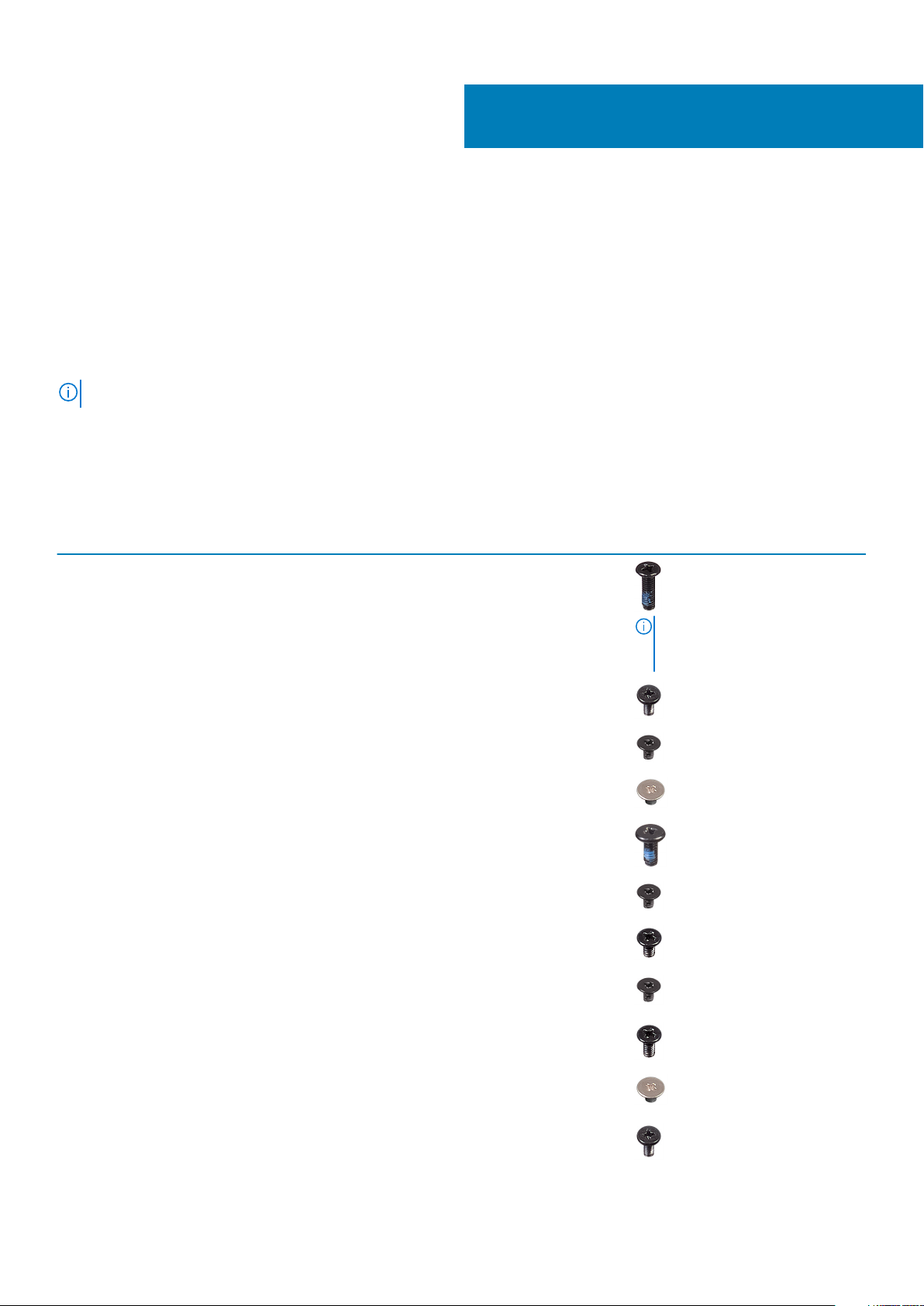
Table 1. Screw list
Component Screw type Quantity Screw image
Base cover
M2.5x7
M2x4
6
1
2
Battery M2x3 4
Display panel M2x2 4
System Fan M2x5 3
Hard-drive assembly M2x3 4
Hard-drive bracket M3x3 4
Heat sink M2x3 3
Hinges
M2.5x2.5
M2x2
NOTE: Screw color may vary
depending on the
configuration ordered.
8
2
I/O board M2x4 1
Komponentide eemaldamine ja paigaldamine 9
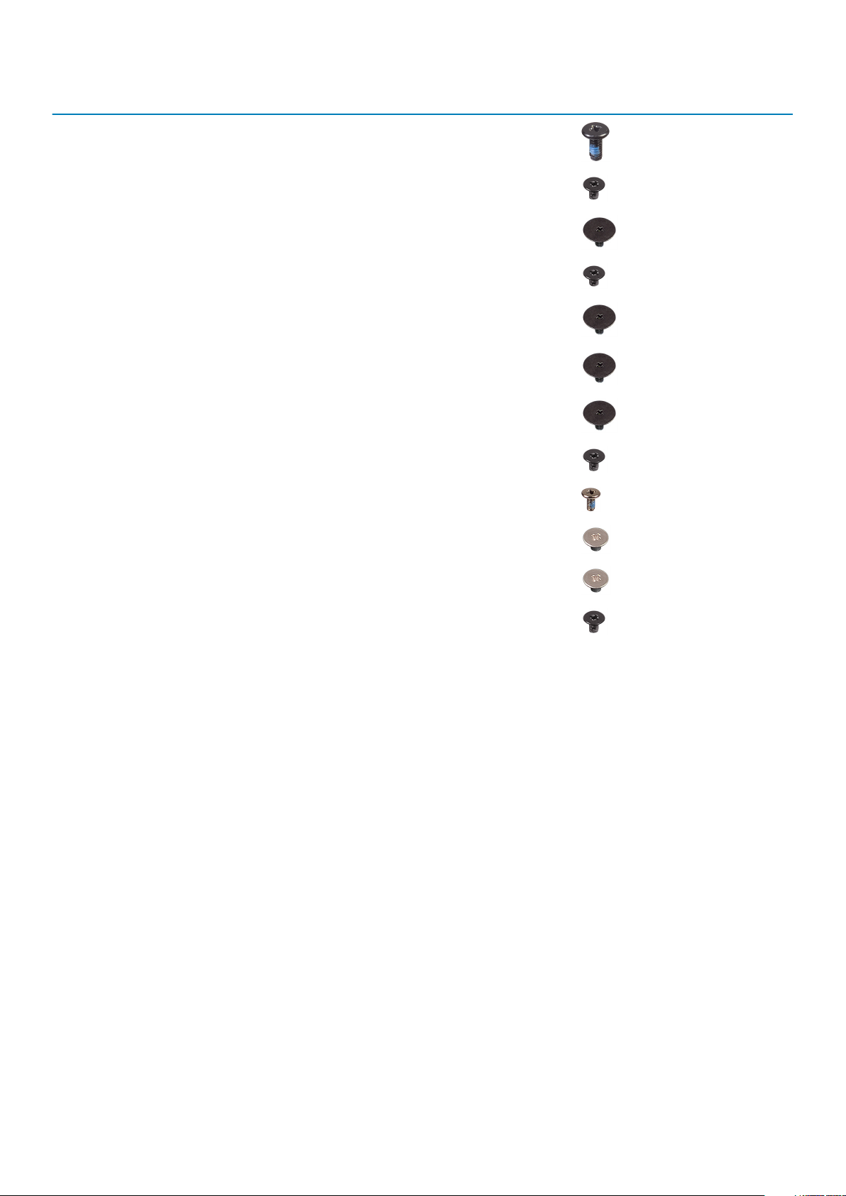
Component Screw type Quantity Screw image
Optical-drive assembly M2x4
Optical-drive bracket M2x3 2
Optical-drive connector board M2x2 Big Head 1
Power-adapter port M2x3 1
Power-button board M2x2 Big Head 1
Power button with fingerprint
reader (optional)
Solid-state drive to thermal plate M2x2 Big Head 1
Solid-state drive M2x0.8x2.2 1
System board M2x4 1
Touchpad M2x2 4
Touch pad bracket M2x2 2
Wireless-card bracket M2x3 1
M2x2 Big Head 1
Micro Secure Digital Card
Removing the Micro Secure Digital card
Prerequisites
1. Follow the procedure in Before working inside your computer
Steps
1. Push the micro secure digital card to release it from the computer.
2. Slide the micro secure digital card out of the computer.
10
Komponentide eemaldamine ja paigaldamine
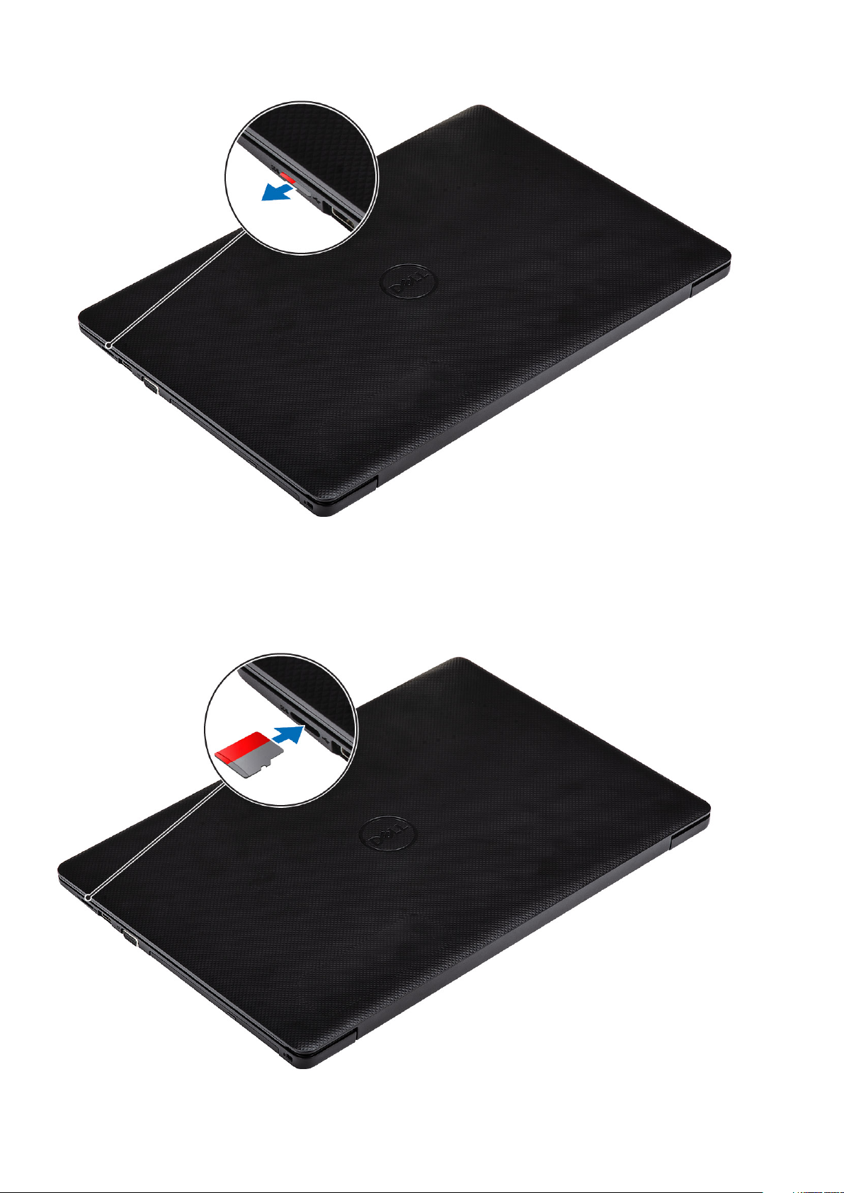
Installing the Micro Secure Digital card
Steps
Slide the micro secure digital into the slot until it clicks into place.
Komponentide eemaldamine ja paigaldamine
11
Next steps
1. Follow the procedure in after working inside your computer
Optilise draivi moodul
Removing the optical drive assembly
Prerequisites
1. Follow the procedure in before working inside your computer
2. Remove the micro SD card
Steps
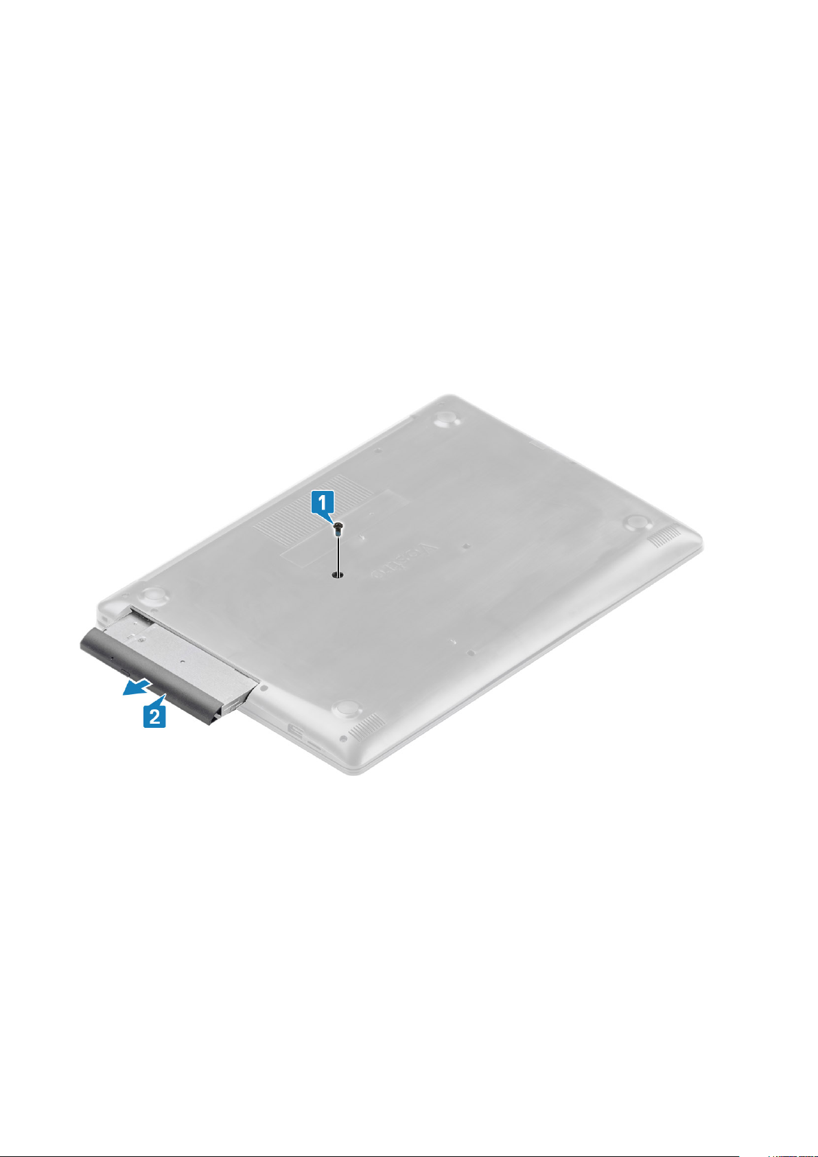
1. Remove the single (M2x4) screw that secures the optical drive to the system [1].
2. Slide the optical drive out of the computer [2].
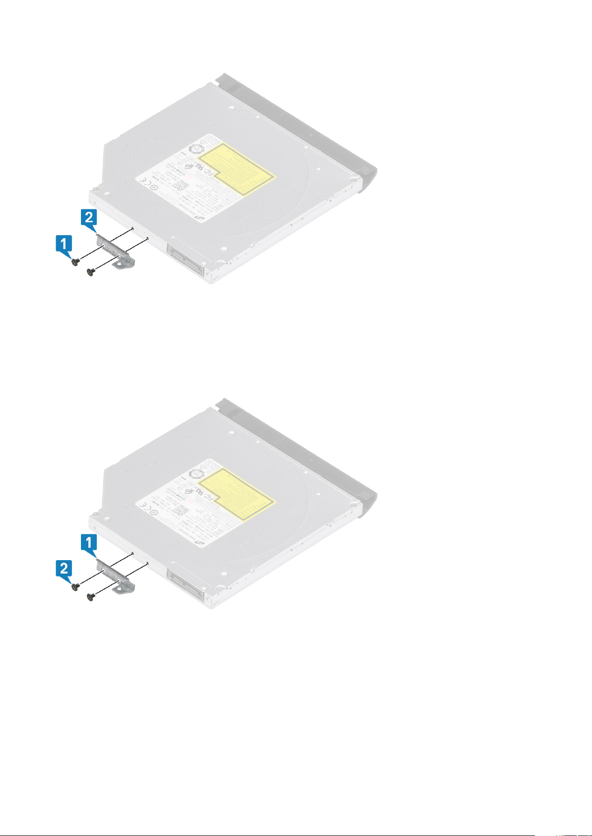
3. Remove the two (M2x3) screws that secure the optical drive bracket to the optical drive [1].
4. Remove the optical drive bracket from the optical drive [2].
12
Komponentide eemaldamine ja paigaldamine
Installing the optical drive assembly
Steps
1. Align the optical drive bracket to the screw holes on the optical drive [1].
2. Replace the two (M2x3) screws that secure the optical drive bracket to the optical drive [2].
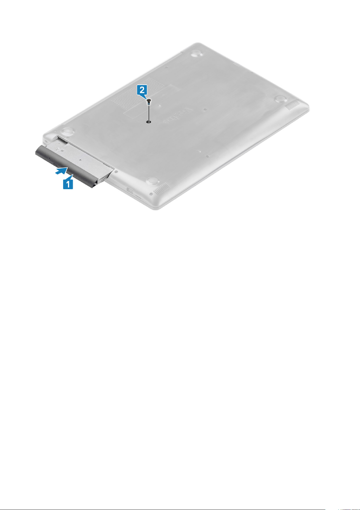
3. Insert the optical drive into the slot until it clicks into place [1].
4. Replace the single (M2x4) screw that secures the optical drive to the system [2].
Komponentide eemaldamine ja paigaldamine
13
Next steps
1. Replace the micro SD card
2. Follow the procedure in after working inside your computer
tagakaas
Removing the base cover
Prerequisites
1. Follow the procedure in before working inside your computer
2. Remove the SD memory card
3. Remove the optical drive assembly
Steps
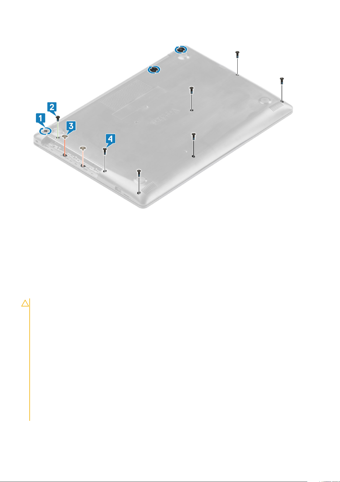
1. Loosen the three captive screws [1].
2. Remove the single (M2x4) screw, two (M2x2) screws, and six (M2.5x7) screws that secure the base cover to the palmrest and
keyboard assembly [2, 3, 4].
14
Komponentide eemaldamine ja paigaldamine

3. Use a prying tool and remove the base cover from the system [5].
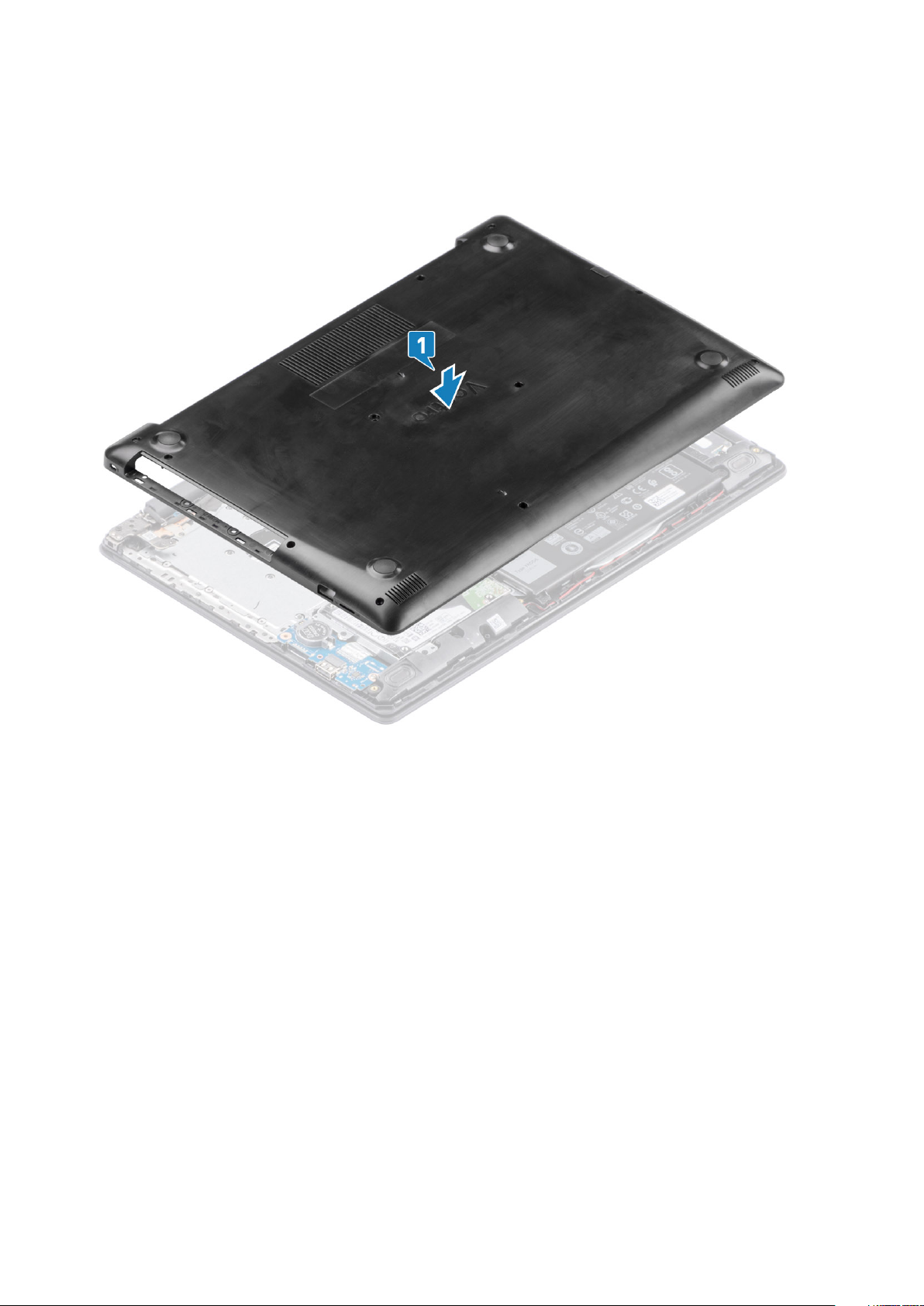
4. Lift the left side of the base cover and remove it off the system [1].
Komponentide eemaldamine ja paigaldamine
15
Installing the base cover
Steps
1. Replace the base cover on the palmrest and keyboard assembly [1].
2. Replace the two (M2x2) screws, and six (M2.5x7) screws that secure the base cover to the palmrest and keyboard assembly [3, 4].
16
Komponentide eemaldamine ja paigaldamine
Next steps
1. Replace the optical drive assembly
2. Replace the SD memory card
3. Follow the procedure in after working inside your computer
aku
Liitiumioonaku ettevaatusabinõud
ETTEVAATUST
• Olge liitiumioonakude käsitsemisel ettevaatlik.
• Tühjendage aku enne selle süsteemist eemaldamist nii palju kui võimalik. Seda on võimalik teha, kui eemaldate
vahelduvvooluadapteri süsteemist, et aku saaks tühjendada.
• Aku purustamine, moonutamine ja läbistamine võõrkehadega ning akule võõrkehade kukutamine on keelatud.
• Hoida akut kõrgete temperatuuride eest, vastasel juhul jaotada akupaketid ja elemendid osadeks.
• Ärge avaldage survet aku pinnale.
• Ärge painutage akut.
• Ärge kasutage mis tahes tööriistu, et akut kangutada.
• Veenduge, et selle toote hooldamise ajal poleks kruvid kadunud ega valesti paigaldatud, et vältida aku ja teiste
süsteemikomponentide juhuslikku torkamist või kahjustumist.
• Kui aku on paisumise tulemusena arvutis kinni, ärge üritage seda vabaks kangutada, kuna liitium-ioonaku torkamine,
painutamine või purustamine võib olla ohtlik. Sellisel juhul võtke abi saamiseks ühendust Delli tehnilise toega. Vt
www.dell.com/contactdell.
• Ostke alati originaalakusid veebisaidilt www.dell.com Delli volitatud partneritelt või edasimüüjatelt.
:
Komponentide eemaldamine ja paigaldamine 17
Removing the battery
Prerequisites
1. Follow the procedure in before working inside your computer
2. Remove the SD memory card
3. Remove the optical drive assembly
4. Remove the base cover
Steps
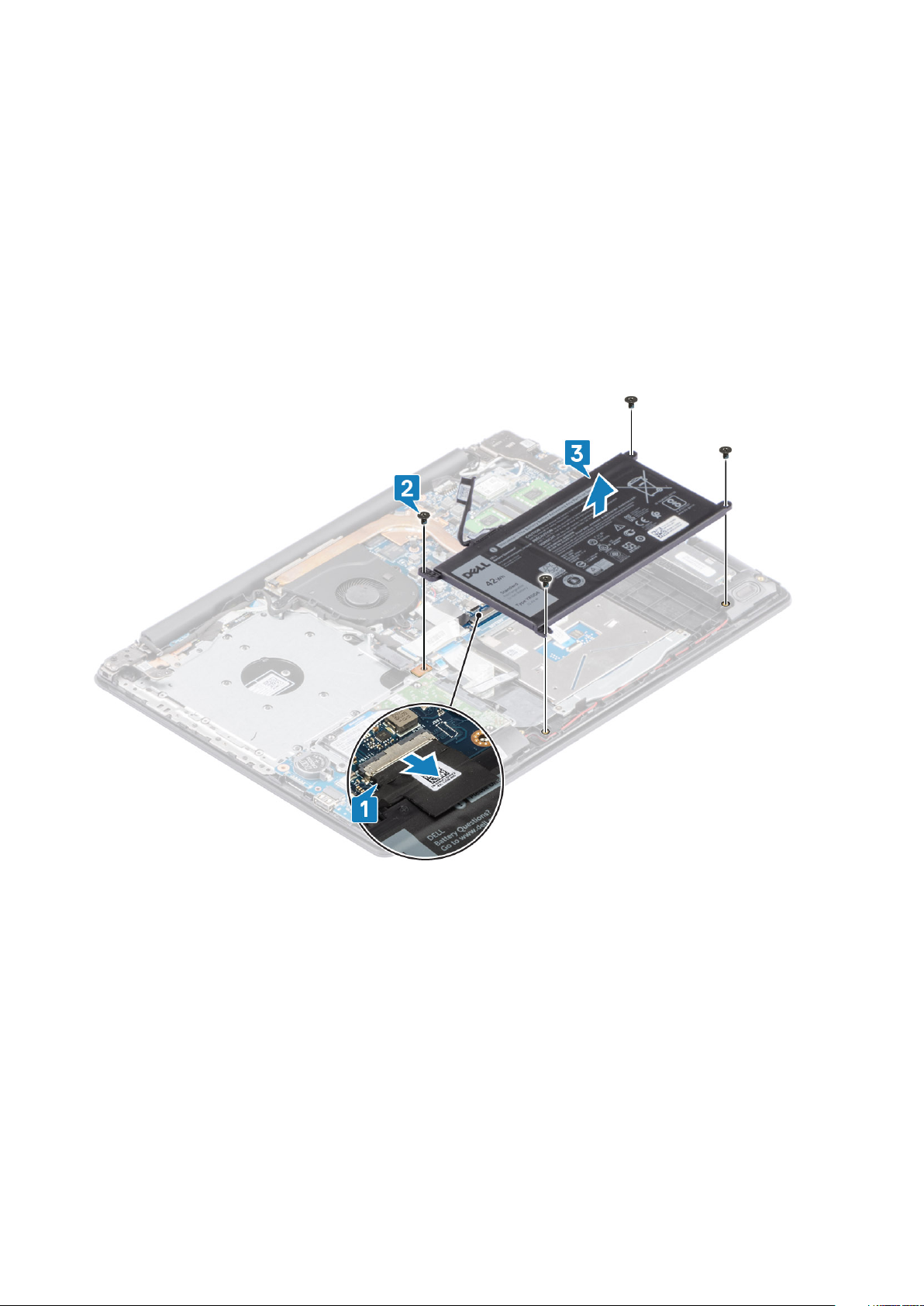
1. Disconnect the battery cable from the system board [1].
2. Remove the four (M2x3) screws that secure the battery to the palmrest and keyboard assembly [2].
3. Lift the battery off the palmrest and keyboard assembly [3].
Installing the battery
Steps
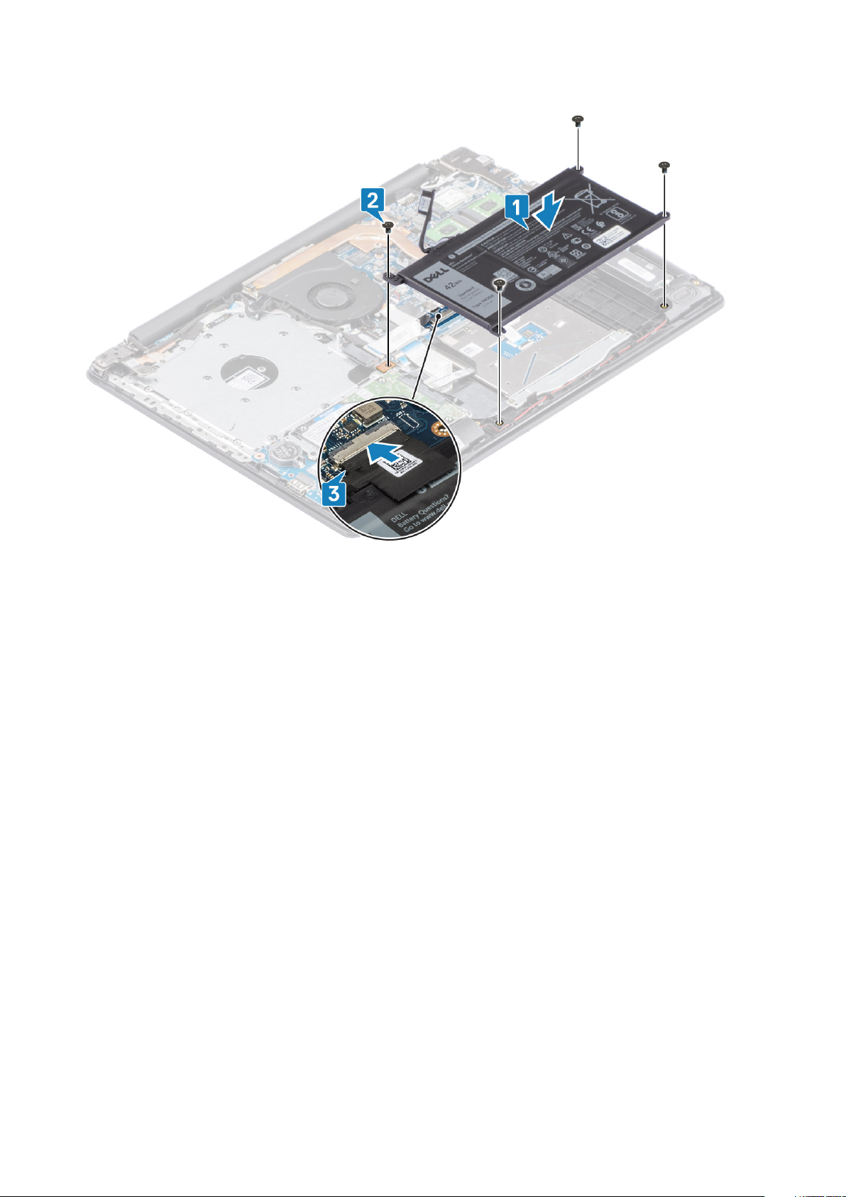
1. Align the screw holes on the battery with the screw holes on the palmrest and keyboard assembly [1].
2. Replace the four (M2x3) screws that secure the battery to the palmrest and keyboard assembly [2].
3. Connect the battery cable to the system board [3].
18
Komponentide eemaldamine ja paigaldamine
Next steps
1. Replace the base cover
2. Replace the optical drive assembly
3. Replace the SD memory card
4. Follow the procedure in after working inside your computer
Mälumoodulid
Removing the memory module
Prerequisites
1. Follow the procedure in before working inside your computer
2. Remove the SD memory card
3. Remove the base cover
4. Disconnect the battery cable from the connector on the system board.
Steps
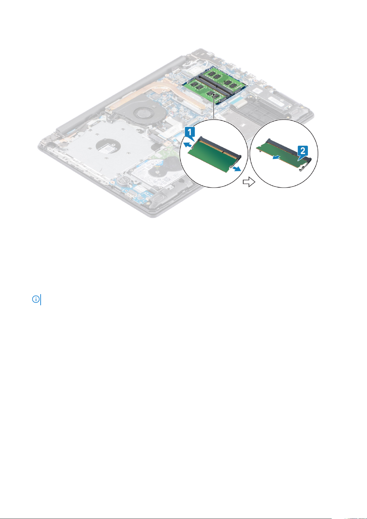
1. Pry the clips securing the memory module until the memory module pops-up [1].
2. Remove the memory module from the memory module slot [2].
Komponentide eemaldamine ja paigaldamine
19
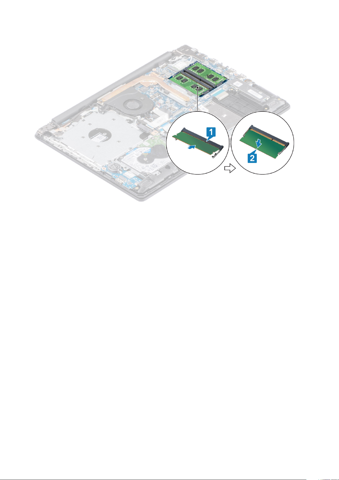
Installing the memory module
Steps
1. Align the notch on the memory module with the tab on the memory module slot and slide the memory module firmly into the slot at an
angle [1].
2. Press the memory module down until the clips secure it [2].
NOTE: If you do not hear the click, remove the memory module and reinstall it.
20 Komponentide eemaldamine ja paigaldamine
Next steps
1. Connect the battery cable to the connector on the system board.
2. Replace the base cover
3. Replace the optical drive assembly
4. Replace the SD memory card
5. Follow the procedure in after working inside your computer
WLAN-kaart
Removing the WLAN card
Prerequisites
1. Follow the procedure in before working inside your computer
2. Remove the SD memory card
3. Remove the optical drive assembly
4. Remove the base cover
5. Disconnect the battery cable from the connector on the system board.
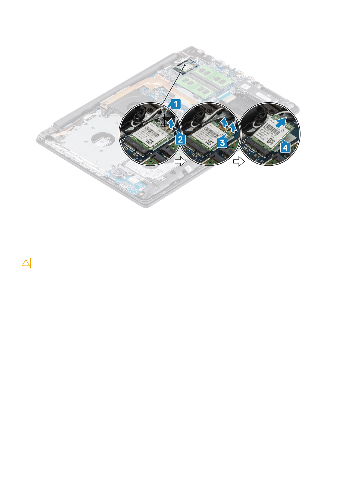
Steps
1. Remove the single (M2x3) screw that secures the WLAN card bracket to the system board [1].
2. Slide and remove the WLAN card bracket that secures the WLAN cables [2].
3. Disconnect the WLAN cables from the connectors on the WLAN card [3].
4. Lift the WLAN card away from the connector [4].
Komponentide eemaldamine ja paigaldamine
21
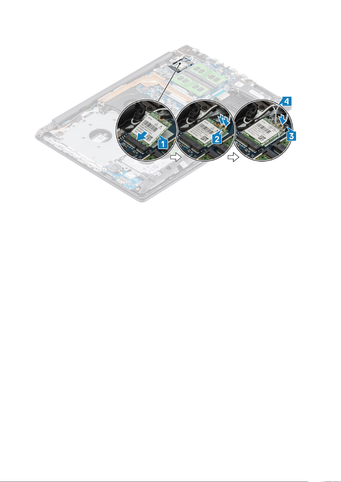
Installing the WLAN card
About this task
CAUTION: To avoid damage to the WLAN card, do not place any cables under it.
Steps
1. Replace the WLAN card into the connector on the system board [1].
2. Connect the WLAN cables to the connectors on the WLAN card [2].
3. Place the WLAN card bracket to secure the WLAN cables to the WLAN card [3].
4. Replace the single (M2x3) screw to secure the WLAN bracket to the WLAN card [4].
22
Komponentide eemaldamine ja paigaldamine
Next steps
1. Connect the battery cable to the connector on the system board.
2. Replace the base cover
3. Replace the optical drive assembly
4. Replace the SD memory card
5. Follow the procedure in after working inside your computer
Solid-state drive/Intel Optane (Optional)
Removing the M.2 2230 Solid-state drive
Prerequisites
1. Follow the procedure in before working inside your computer
2. Remove the SD memory card
3. Remove the optical drive assembly
4. Remove the base cover
5. Disconnect the battery cable from the connector on the system board.
Steps
1. Loosen the captive screw that secures the thermal plate to the palmrest and keyboard assembly [1].
2. Remove the single (M2x3) screw that secures the thermal plate to the palmrest and keyboard assembly [2].
3. Slide and remove the thermal plate from the solid-state drive [3].
Komponentide eemaldamine ja paigaldamine
23
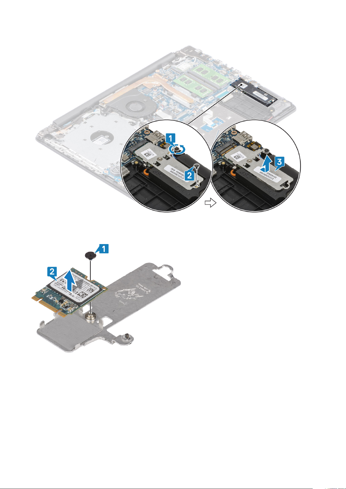
4. Turn the thermal plate over.
5. Remove the single (M2x2) screw that secures the solid-state drive to the thermal plate [1].
6. Lift the solid-state drive off the thermal plate [2].
Installing the M.2 2230 Solid-state drive
Steps
1. Place the solid-state drive into the thermal plate slot [1].
2. Replace the single (M2x2) screw that secures the solid-state drive to the thermal plate [2].
24
Komponentide eemaldamine ja paigaldamine

3. Align the notch on the solid-state drive with the tab on the solid-state drive slot.
4. Slide and insert the tab of the solid-state drive into the solid-state drive slot [1,2].
5. Tighten the captive screw that secures the thermal plate to the palmrest and keyboard assembly [2].
6. Replace the single (M2x3) screw that secures the thermal plate to the palmrest and keyboard assembly [3].
Next steps
1. Connect the battery cable to the connector on the system board.
2. Replace the base cover
3. Replace the optical drive assembly
4. Replace the SD memory card
5. Follow the procedure in after working inside your computer
Komponentide eemaldamine ja paigaldamine
25
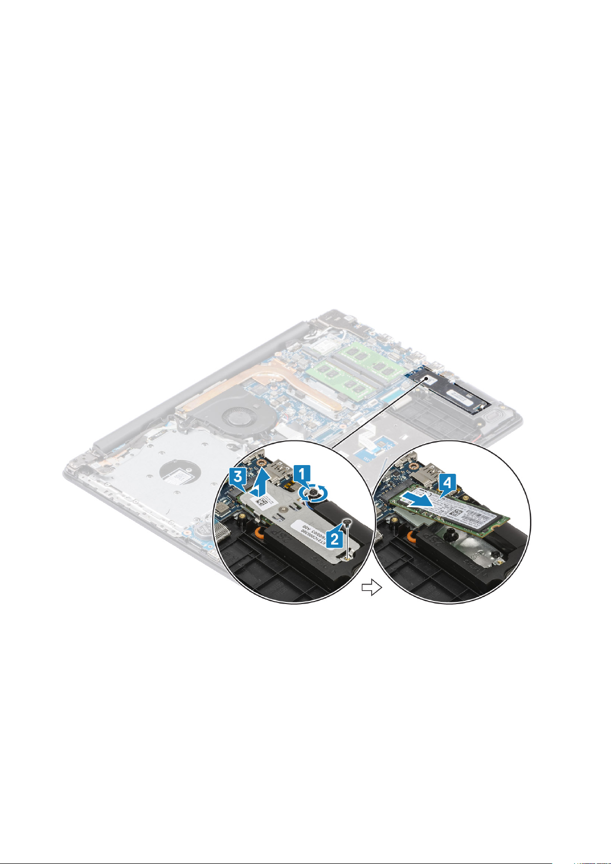
Removing the M.2 2280 Solid-state drive or Intel Optane memory - Optional
Prerequisites
1. Follow the procedure in before working inside your computer
2. Remove the SD memory card
3. Remove the optical drive assembly
4. Remove the base cover
5. Disconnect the battery cable from the connector on the system board.
Steps
1. Loosen the captive screw that secures the thermal plate to the palmrest and keyboard assembly [1].
2. Remove the single (M2x3) screw that secures the thermal plate to the palmrest and keyboard assembly [2].
3. Slide and remove the thermal plate from the solid-state drive/Intel Optane slot [3].
4. Slide and lift the solid-state drive/Intel Optane off the palmrest and keyboard assembly [4].
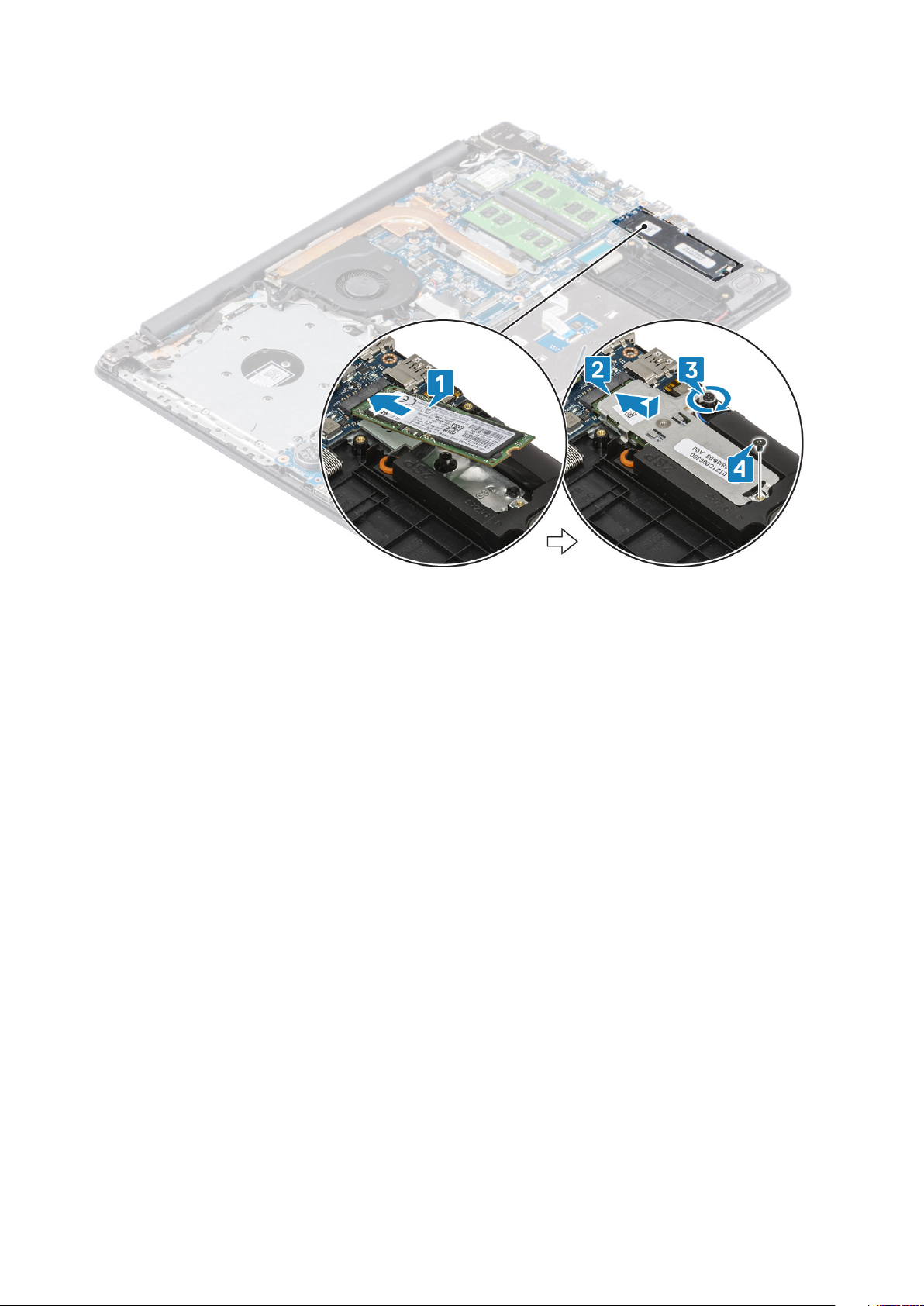
Installing the M.2 2280 Solid-state drive or Intel Optane memory - Optional
Steps
1. Slide and insert the tab of the solid-state drive/Intel Optane into the solid-state drive/Intel Optane slot [1, 2].
2. Align the thermal plate on the solid-state drive and tighten the captive screw that secures the thermal plate to the palmrest and
keyboard assembly [3].
3. Replace the single (M2x3) screw that secures the thermal plate to the palmrest and keyboard assembly [4].
26
Komponentide eemaldamine ja paigaldamine
Next steps
1. Connect the battery cable to the connector on the system board.
2. Replace the base cover
3. Replace the optical drive assembly
4. Replace the SD memory card
5. Follow the procedure in after working inside your computer
Nööppatarei
Removing the coin-cell
Prerequisites
1. Follow the procedure in before working inside your computer
2. Remove the SD memory card
3. Remove the optical drive assembly
4. Remove the base cover
5. Disconnect the battery cable from the connector on the system board.
Steps
1. Using a plastic scribe, gently pry the coin-cell battery out of the slot on the I/O board [1].
2. Remove the coin-cell battery away from the system [2].
Komponentide eemaldamine ja paigaldamine
27
 Loading...