

Dell Vostro 3591 User Manual [ro]

Dell Vostro 3591 (With optical drive)
Service Manual
Regulatory Model: P75F
Regulatory Type: PP75F013

Note, atenţionări şi avertismente
NOTIFICARE: O NOTĂ indică informaţii importante care vă ajută să optimizaţi utilizarea produsului.
AVERTIZARE: O ATENŢIONARE indică un pericol potenţial de deteriorare a hardware-ului sau de pierdere de date şi vă
arată cum să evitaţi problema.
AVERTISMENT: Un AVERTISMENT indică un pericol potenţial de deteriorare a bunurilor, de vătămare corporală sau de
deces.
© 2020 Dell Inc. sau filialele sale. Toate drepturile rezervate. Dell, EMC şi alte mărci comerciale sunt mărci comerciale ale Dell Inc.
sau ale filialelor sale. Alte mărci comerciale pot fi mărci comerciale deţinute de proprietarii respectivi.
2020 - 02
Rev. A00

Contents
1 Efectuarea lucrărilor în interiorul computerului................................................................................6
Instrucţiuni de siguranţă........................................................................................................................................................6
Înainte de a efectua lucrări în interiorul computerului..................................................................................................6
Descărcări electrostatice – protecţia împotriva descărcărilor electrostatice...........................................................7
Kit de service pe teren ESD............................................................................................................................................7
Transportarea componentelor sensibile........................................................................................................................8
După efectuarea lucrărilor în interiorul computerului...................................................................................................9
2 Scoaterea şi instalarea componentelor..........................................................................................10
Instrumentele recomandate................................................................................................................................................10
Screw list...............................................................................................................................................................................10
Micro Secure Digital Card.................................................................................................................................................... 11
Removing the Micro Secure Digital card......................................................................................................................11
Installing the Micro Secure Digital card....................................................................................................................... 12
Ansamblul unității optice......................................................................................................................................................13
Removing the optical drive assembly...........................................................................................................................13
Installing the optical drive assembly.............................................................................................................................14
Capacul bazei........................................................................................................................................................................15
Removing the base cover..............................................................................................................................................15
Installing the base cover................................................................................................................................................ 17
Baterie....................................................................................................................................................................................18
Lithium-ion battery precautions................................................................................................................................... 18
Removing the battery....................................................................................................................................................19
Installing the battery...................................................................................................................................................... 19
Modulele de memorie..........................................................................................................................................................20
Removing the memory module....................................................................................................................................20
Installing the memory module....................................................................................................................................... 21
placa WLAN..........................................................................................................................................................................22
Removing the WLAN card............................................................................................................................................22
Installing the WLAN card.............................................................................................................................................. 23
Solid-state drive/Intel Optane (Optional)........................................................................................................................ 24
Removing the M.2 2230 Solid-state drive................................................................................................................. 24
Installing the M.2 2230 Solid-state drive....................................................................................................................25
Removing the M.2 2280 Solid-state drive or Intel Optane memory - Optional.....................................................27
Installing the M.2 2280 Solid-state drive or Intel Optane memory - Optional....................................................... 27
Bateria rotundă.................................................................................................................................................................... 28
Removing the coin-cell................................................................................................................................................. 28
Installing the coin-cell battery...................................................................................................................................... 29
Hard disk...............................................................................................................................................................................30
Removing the hard drive assembly............................................................................................................................. 30
Installing the hard drive assembly................................................................................................................................32
Ventilator sistem..................................................................................................................................................................34
Removing the system fan.............................................................................................................................................34
Installing the system fan...............................................................................................................................................35
Contents 3

Radiatorul..............................................................................................................................................................................37
Removing the heatsink..................................................................................................................................................37
Installing the heatsink....................................................................................................................................................38
Removing the heatsink................................................................................................................................................. 38
Installing the heatsink....................................................................................................................................................39
Boxe...................................................................................................................................................................................... 40
Removing the speakers................................................................................................................................................ 40
Installing the speakers....................................................................................................................................................41
Placă I/O...............................................................................................................................................................................42
Removing the IO board.................................................................................................................................................42
Installing the IO board................................................................................................................................................... 44
Touchpad..............................................................................................................................................................................45
Removing the touch pad assembly............................................................................................................................. 45
Installing the touch pad assembly................................................................................................................................47
Ansamblul afişajului..............................................................................................................................................................49
Removing the display assembly................................................................................................................................... 49
Installing the display assembly......................................................................................................................................52
Cadrul afişajului.................................................................................................................................................................... 54
Removing the display bezel..........................................................................................................................................54
Installing the display bezel ........................................................................................................................................... 54
Placa butonului de alimentare............................................................................................................................................55
Removing the power button board.............................................................................................................................55
Installing the power button board............................................................................................................................... 56
Placa de sistem.................................................................................................................................................................... 57
Removing the system board........................................................................................................................................ 57
Installing the system board...........................................................................................................................................59
Port adaptor de alimentare................................................................................................................................................. 61
Removing the power adapter port...............................................................................................................................61
Installing the power adapter port................................................................................................................................ 62
Cameră..................................................................................................................................................................................63
Removing the camera...................................................................................................................................................63
Installing the camera..................................................................................................................................................... 64
Panoul afișajului....................................................................................................................................................................65
Removing the display panel..........................................................................................................................................65
Installation display panel................................................................................................................................................67
Balamalele afișajului............................................................................................................................................................. 69
Removing the display hinges........................................................................................................................................69
Installing the display hinges.......................................................................................................................................... 70
Cablul afișajului......................................................................................................................................................................71
Removing the display cable...........................................................................................................................................71
Installing the display cable.............................................................................................................................................72
Ansamblul capacului din spate al afișajului și al antenei...................................................................................................73
Removing the display back-cover................................................................................................................................73
Installing the display back-cover..................................................................................................................................75
Ansamblul zonei de sprijin pentru mâini şi al tastaturii.................................................................................................... 76
Removing the palmrest and keyboard assembly....................................................................................................... 76
3 Configurarea sistemului.............................................................................................................. 78
Boot menu............................................................................................................................................................................ 78
Tastele de navigare............................................................................................................................................................. 78
4
Contents

Opțiuni de configurare a sistemului................................................................................................................................... 79
Opţiuni generale............................................................................................................................................................. 79
Informaţii sistem.............................................................................................................................................................79
Video............................................................................................................................................................................... 80
Security (Securitate).....................................................................................................................................................80
Secure Boot (Încărcare securizată)............................................................................................................................ 82
Intel Software Guard Extensions (Extensii de protecţie software Intel)................................................................82
Performance (Performanţe)........................................................................................................................................ 83
Gestionarea alimentării..................................................................................................................................................83
POST Behavior (Comportament POST)....................................................................................................................84
Virtualization Support (Suport virtualizare)............................................................................................................... 85
Wireless...........................................................................................................................................................................86
Ecranul Maintenance (Întreţinere).............................................................................................................................. 86
System Logs (Jurnale de sistem)................................................................................................................................86
SupportAssist System Resolution (Rezoluţie sistem SupportAssist)..................................................................... 87
Parola de sistem și de configurare.....................................................................................................................................87
Atribuirea unei parole de configurare a sistemului..................................................................................................... 87
Ștergerea sau modificarea unei parole de configurare a sistemului existente....................................................... 88
4 Depanare................................................................................................................................... 89
Diagnosticarea prin evaluarea îmbunătățită a sistemului la preîncărcare – diagnosticare ePSA...............................89
Executarea diagnosticării ePSA................................................................................................................................... 89
Indicatoarele luminoase de diagnosticare a sistemului....................................................................................................89
Actualizarea BIOS (cheie USB)......................................................................................................................................... 90
Actualizarea sistemului BIOS.............................................................................................................................................. 91
Opțiuni pentru copia de rezervă și recuperare................................................................................................................. 91
Ciclul de alimentare Wi-Fi....................................................................................................................................................91
Eliberarea electricităţii reziduale......................................................................................................................................... 91
5 Solicitarea de asistenţă...............................................................................................................93
Cum se poate contacta Dell...............................................................................................................................................93
Contents
5

Efectuarea lucrărilor în interiorul computerului
Instrucţiuni de siguranţă
Cerințe preliminare
Utilizaţi următoarele instrucţiuni de siguranţă pentru a vă proteja computerul împotriva eventualelor deteriorări şi a vă asigura siguranţa
personală. Doar dacă nu există alte specificaţii, fiecare procedură inclusă în acest document presupune existenţa următoarelor condiţii:
• Aţi citit informaţiile privind siguranţa livrate împreună cu computerul.
• O componentă poate fi înlocuită sau, dacă este achiziţionată separat, instalată prin efectuarea procedurii de scoatere în ordine inversă.
Despre această sarcină
NOTIFICARE: Deconectaţi toate sursele de alimentare înainte de a deschide capacul sau panourile computerului. După ce
terminați lucrările în interiorul computerului, remontați toate capacele, panourile și șuruburile înainte de conectarea la
sursa de alimentare.
AVERTISMENT: Înainte de a efectua lucrări în interiorul computerului, citiţi instrucţiunile de siguranţă livrate împreună
cu computerul. Pentru informații suplimentare privind cele mai bune practici de siguranță, consultați Pagina de pornire
pentru conformitatea cu reglementările.
1
AVERTIZARE: Multe dintre reparaţii pot fi efectuate doar de un tehnician de service autorizat. Efectuaţi doar activităţile
de depanare şi reparaţii simple specificate în documentaţia produsului dvs. sau conform indicaţiilor primite din partea
echipei de asistenţă online sau prin telefon. Deteriorările cauzate de lucrările de service neautorizate de către Dell nu
sunt acoperite de garanţia dvs. Citiţi şi respectaţi instrucţiunile de siguranţă incluse în pachetul produsului.
AVERTIZARE: Pentru a evita descărcarea electrostatică, conectați-vă la împământare utilizând o brățară antistatică sau
atingând periodic o suprafață metalică nevopsită în timp ce atingeți un conector de pe partea din spate a computerului.
AVERTIZARE: Manevraţi componentele şi plăcile cu atenţie. Nu atingeţi componentele sau contactele de pe o placă.
Apucaţi placa de margini sau de suportul de montare metalic. Apucaţi o componentă, cum ar fi un procesor, de margini,
nu de pini.
AVERTIZARE: Când deconectaţi un cablu, trageţi de conector sau de lamela de tragere, nu de cablul propriu-zis. Unele
cabluri au conectori cu lamele de blocare; dacă deconectaţi un cablu de acest tip, apăsaţi pe lamelele de blocare înainte
de a deconecta cablul. În timp ce îndepărtaţi conectorii, menţineţi-i aliniaţi uniform pentru a evita îndoirea pinilor
acestora. De asemenea, înainte de a conecta un cablu, asiguraţi-vă că ambii conectori sunt orientaţi şi aliniaţi corect.
NOTIFICARE: Culoarea computerului dvs. şi anumite componente pot fi diferite faţă de ilustraţiile din acest document.
Înainte de a efectua lucrări în interiorul computerului
Despre această sarcină
Pentru a nu defecta computerul, efectuați următorii pași înainte de a începe lucrările în interiorul computerului.
Pași
1. Asigurați-vă că urmați Instrucțiunile de siguranță.
2. Asigurați-vă că suprafața de lucru este dreaptă și curată, pentru a nu zgâria capacul computerului.
3. Opriţi computerul.
4. Deconectați toate cablurile de rețea de la computer.
6 Efectuarea lucrărilor în interiorul computerului

AVERTIZARE: Pentru a deconecta un cablu de reţea, întâi decuplaţi cablul de la computer, apoi decuplaţi-l de la
dispozitivul de reţea.
5. Deconectați computerul și toate dispozitivele atașate de la prizele de curent.
6. După ce computerul este deconectat de la rețeaua electrică, apăsați și țineți apăsat butonul de alimentare pentru a conecta placa de
sistem la împământare.
NOTIFICARE: Pentru a evita descărcarea electrostatică, conectați-vă la împământare utilizând o brățară antistatică
sau atingând periodic o suprafață metalică nevopsită în timp ce atingeți un conector de pe partea din spate a
computerului.
Descărcări electrostatice – protecţia împotriva descărcărilor electrostatice
Descărcările electrostatice reprezintă o preocupare majoră atunci când mânuiţi componente electronice, mai ales componente sensibile
precum plăci de extensie, procesoare, module de memorie DIMM şi plăci de sistem. Sarcini electrice neglijabile pot deteriora circuitele în
moduri greu de observat, cum ar fi funcţionarea cu intermitenţe sau scurtarea duratei de viaţă a produsului. Pe măsură ce în domeniu se
impun cerinţe de consum de energie cât mai mic la o densitate crescută, protecţia împotriva descărcărilor electrostatice devine o
preocupare din ce în ce mai mare.
Datorită densităţii crescute a semiconductorilor utilizaţi în produsele Dell recente, sensibilitatea faţă de deteriorări statice este acum mai
mare comparativ cu produsele Dell anterioare. Din acest motiv, unele dintre metodele de manevrare a componentelor aprobate în trecut nu
mai sunt aplicabile.
Sunt recunoscute două tipuri de deteriorări prin descărcări electrostatice, catastrofale şi intermitente.
• Catastrofale – Defecţiunile catastrofale reprezintă aproximativ 20% dintre defecţiunile legate de descărcările electrostatice. O astfel
de defecţiune provoacă o pierdere imediată şi totală a capacităţii de funcţionare a dispozitivului. Un exemplu de defecţiune catastrofală
este un modul de memorie DIMM supus unui şoc electrostatic care generează imediat un simptom de tip "No POST/No Video" cu
emiterea unui cod sonor de memorie lipsă sau nefuncţională.
• Intermitente – Defecţiunile intermitente reprezintă aproximativ 80% dintre defecţiunile legate de descărcările electrostatice.
Procentul mare de defecţiuni intermitente se datorează faptului că momentul în care survine defecţiunea nu este observat imediat.
Modulul DIMM primeşte un şoc electrostatic pe care îl absoarbe doar parţial ca o mică diferenţă de potenţial, fără să producă imediat
simptome către exterior legate de defecţiune. Disiparea diferenţei slabe de potenţial poate dura săptămâni sau luni, timp în care poate
provoca degradarea integrităţii memoriei, erori de memorie intermitente etc.
Defecţiunile cele mai dificile de depistat şi de depanat sunt cele intermitente (cunoscute şi ca defecţiuni latente sau "răni deschise").
Pentru a preveni defecţiunile prin descărcări electrostatice, urmaţi aceşti paşi:
• Utilizaţi o brăţară anti-statică de încheietură, cablată şi împământată corespunzător. Utilizarea brăţărilor anti-statice wireless nu mai
este permisă; acestea nu asigură o protecţie adecvată. Atingerea şasiului înainte de a manevra componente nu asigură o protecţie
adecvată împotriva descărcărilor electrostatice pentru componentele cu o sensibilitate electrostatică crescută.
• Manevraţi toate componentele sensibile la descărcări electrostatice într-o zonă protejată anti-static. Dacă este posibil, folosiţi covoare
antistatice de podea sau de birou.
• Când despachetaţi o componentă sensibilă electrostatic din cutia în care a fost livrată, nu scoateţi componenta din punga anti-statică
până în momentul în care sunteţi pregătit să instalaţi componenta. Înainte să desfaceţi ambalajul anti-static, asiguraţi-vă că aţi
descărcat electricitatea statică din corpul dvs.
• Înainte de a transporta o componentă sensibilă electrostatic, aşezaţi-o într-un container sau ambalaj anti-static.
Kit de service pe teren ESD
Kitul de service pe teren nemonitorizat este cel mai frecvent utilizat kit de servicii. Fiecare kit de service pe teren conţine trei componente
principale: covoraş antistatic, bandă de mână şi cablu de legătură.
Componentele unui kit de service pe teren ESD
Componentele unui kit de service pe teren ESD sunt:
• Covoraş antistatic – covoraşul antistatic are proprietăţi disipative şi permite aşezarea pieselor pe acesta în timpul procedurilor de
service. Când utilizaţi un covoraş antistatic, banda de mână trebuie să fie comodă, iar cablul de legătură trebuie să fie conectat la
covoraş şi la orice suprafaţă metalică expusă de pe sistemul la care se lucrează. După instalarea corectă, piesele de reparat pot fi
extrase din recipientul ESD şi aşezate direct pe covoraş. Obiectele sensibile la ESD sunt în siguranţă în mâna dvs., pe covoraşul ESD, în
sistem sau într-o geantă.
Efectuarea lucrărilor în interiorul computerului
7

• Banda de mână şi cablul de legătură – banda de mână şi cablul de legătură pot fi conectate fie direct între încheietura dvs. şi o
porţiune metalică expusă de pe componentele hardware, dacă covoraşul ESD nu este necesar, fie conectate la covoraşul antistatic,
pentru a proteja componentele hardware aşezate temporar pe covoraş. Conexiunea fizică formată de banda de mână şi cablul de
legătură între pielea dvs., covoraşul ESD şi componentele hardware este cunoscută sub numele de legătură. Utilizaţi numai kituri de
service pe teren cu bandă de mână, covoraş şi cablu de legătură. Nu utilizaţi niciodată benzi de mână wireless. Reţineţi întotdeauna că
firele interne ale unei benzi de mână sunt expuse la deteriorări din cauza uzurii şi trebuie verificate cu regularitate cu ajutorul unui tester
pentru benzi de mână pentru a evita deteriorarea accidentală a componentelor hardware din cauza ESD. Se recomandă testarea benzii
de mână şi a cablului de legătură cel puţin o dată pe săptămână.
• Tester ESD pentru benzi de mână – firele din interiorul unei benzi de mână ESD sunt expuse la deteriorări în timp. Când utilizaţi un
kit nemonitorizat, se recomandă testarea cu regularitate a benzii înainte de fiecare apel de service, precum şi testarea cel puţin o dată
pe săptămână. Testerul pentru benzi de mână este cea mai bună metodă pentru a efectua acest test. Dacă nu aveţi propriul dvs. tester
pentru benzi de mână, vedeţi dacă nu există unul la biroul dvs. regional. Pentru a efectua testul, conectaţi cablul de legătură al benzii de
mână la tester, când banda este prinsă la încheietura dvs., şi apăsaţi pe buton pentru a testa. Dacă testul a reuşit, se aprinde un LED
verde; dacă testul nu reuşeşte, se aprinde un LED roşu şi se aude o alarmă.
• Elemente de izolaţie – este esenţial ca dispozitivele sensibile la ESD, precum carcasele de plastic ale disipatoarelor termice, să fie
ţinute la distanţă de piese interne izolatoare şi care sunt, deseori, încărcate cu sarcini electrice ridicate.
• Mediu de lucru – înainte de instalarea kitului de service de teren ESD, evaluaţi situaţia la locaţia clientului. De exemplu, instalarea
kitului pentru un mediu server este diferită faţă de instalarea pentru un mediu desktop sau portabil. În mod caracteristic, serverele sunt
instalate într-un rack în interiorul unui centru de date; desktopurile sau sistemele portabile sunt aşezate, de regulă, pe birouri sau în nişe.
Căutaţi întotdeauna o suprafaţă de lucru amplă şi deschisă, liberă şi suficient de mare, pentru a instala kitul ESD, cu spaţiu suplimentar
pentru tipul de sistem reparat. De asemenea, spaţiul de lucru nu trebuie să conţină elemente izolatoare care pot cauza un eveniment
ESD. În zona de lucru, materiale izolatoare precum Styrofoam şi alte materiale plastice trebuie deplasate întotdeauna la o distanţă de
cel puţin 12 inchi sau 30 cm faţă de piesele sensibile înainte de a manipula fizic orice componente hardware
• Ambalaj ESD – toate dispozitivele sensibile la ESD trebuie trimise şi recepţionate în ambalaj antistatic. Sunt preferate recipientele
metalice, ecranate la electricitate statică. Totuşi, trebuie să returnaţi întotdeauna piesa deteriorată utilizând acelaşi recipient şi ambalaj
ESD ca şi cele în care a sosit piesa nouă. Recipientul ESD trebuie să fie pliat şi închis cu bandă adezivă şi toate materialele de ambalare
din spumă trebuie utilizate în cutia originală în care a sosit piesa nouă. Dispozitivele sensibile la ESD trebuie scoase din ambalaj numai pe
o suprafaţă de lucru protejată la ESD, iar piesele nu trebuie amplasate niciodată pe partea de sus a recipientului ESD, deoarece numai
partea interioară a recipientului este ecranată. Poziţionaţi întotdeauna piesele în mână, pe covoraşul ESD, în sistem sau în interiorul unui
recipient electrostatic.
• Transportul componentelor sensibile – când transportaţi componente sensibile la ESD, precum piese de schimb sau piese care
trebuie returnate la Dell, este esenţial ca aceste piese să fie introduse în recipiente antistatice pentru un transport în condiţii de
siguranţă.
Rezumat de protecţie ESD
Se recomandă ca toţi tehnicienii de service de teren să utilizeze permanent banda de mână de împământare ESD cu fir şi covoraşul
antistatic de protecţie tradiţionale atunci când execută intervenţii de service la produsele Dell. De asemenea, este esenţial ca tehnicienii să
ţină piesele sensibile separat de toate piesele izolatoare în timpul intervenţiei de service, precum şi să utilizeze recipiente antistatice pentru
transportul componentelor sensibile.
Transportarea componentelor sensibile
Când transportaţi componente sensibile la electricitatea statică, cum ar fi piese de schimb sau componente care urmează să fie returnate
la Dell, este foarte important să plasaţi aceste componente în pungi anti-statice pentru a fi transportate în siguranţă.
Ridicarea echipamentului
Când ridicaţi echipamente cu o greutate mare, respectaţi următoarele indicaţii:
AVERTIZARE
ridicare mecanic.
1. Obţineţi un echilibru ferm în picioare. Îndepărtaţi tălpile una de alta pentru o bază stabilă şi îndreptaţi degetele spre exterior.
2. Încordaţi muşchii stomacului. Muşchii abdominali susţin coloana vertebrală în timpul ridicării, absorbind forţa încărcăturii.
3. Ridicaţi folosind muşchii picioarelor, nu ai spatelui.
4. Ţineţi greutatea aproape de corp. Cu cât încărcătura este mai aproape de coloană, cu atât forţa exercitată asupra spatelui este mai
mică.
5. Ţineţi spatele vertical şi când ridicaţi şi când aşezaţi încărcătura. Nu adăugaţi şi greutatea corpului la greutatea încărcăturii. Evitaţi
răsucirea corpului şi a spatelui.
6. Urmaţi aceleaşi tehnici în ordine inversă pentru a aşeza încărcătura.
: Nu ridicaţi mai mult de 50 lb. Obţineţi întotdeauna resurse suplimentare sau folosiţi un dispozitiv de
8
Efectuarea lucrărilor în interiorul computerului

După efectuarea lucrărilor în interiorul computerului
Despre această sarcină
După ce aţi finalizat toate procedurile de remontare, asiguraţi-vă că aţi conectat toate dispozitivele externe, plăcile şi cablurile înainte de a
porni computerul.
Pași
1. Conectaţi toate cablurile de reţea sau de telefonie la computerul dvs.
AVERTIZARE: Pentru a conecta un cablu de reţea, mai întâi conectaţi cablul la dispozitivul de reţea şi apoi conectaţi-l
la computer.
2. Conectaţi computerul şi toate dispozitivele ataşate la prizele electrice.
3. Porniţi computerul.
4. Dacă este necesar, verificaţi funcţionarea corectă a computerului executând programul ePSA diagnostics.
Efectuarea lucrărilor în interiorul computerului 9
Scoaterea şi instalarea componentelor
Instrumentele recomandate
Procedurile din acest document necesită următoarele instrumente:
• Şurubelniţă cu vârf în cruce nr. 0
• Şurubelniţă cu vârf în cruce nr. 1
• Ştift de plastic
NOTIFICARE: Șurubelnița #0 este pentru șuruburile 0-1, iar șurubelnița #1 este pentru șuruburile 2-4.
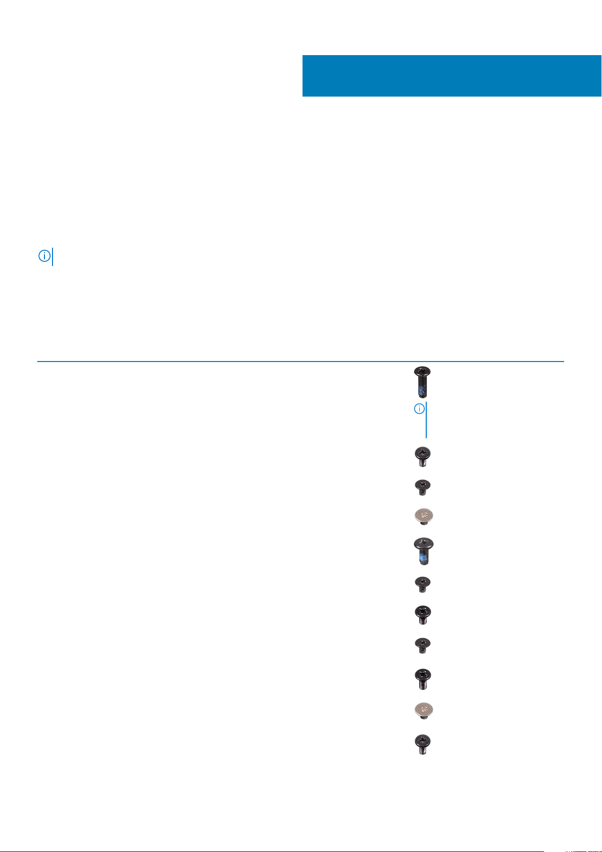
Screw list
The table provides the list of screws that are used for securing different components.
Table 1. Screw list
Component Screw type Quantity Screw image
Base cover
M2.5x7
M2x4
6
1
2
Battery M2x3 4
Display panel M2x2 4
System Fan M2x5 3
Hard-drive assembly M2x3 4
Hard-drive bracket M3x3 4
Heat sink M2x3 3
Hinges
M2.5x2.5
M2x2
NOTE: Screw color may vary
depending on the
configuration ordered.
8
2
I/O board M2x4 1
10 Scoaterea şi instalarea componentelor
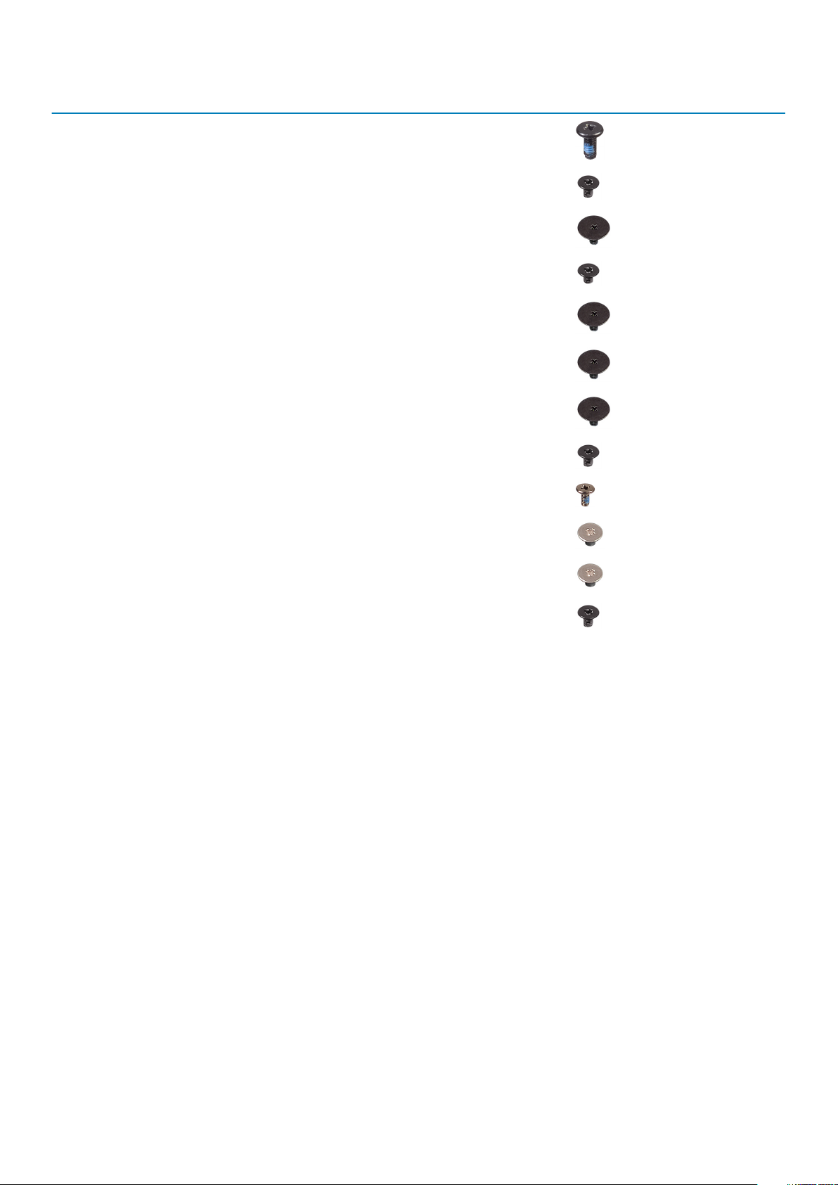
Component Screw type Quantity Screw image
Optical-drive assembly M2x4
Optical-drive bracket M2x3 2
Optical-drive connector board M2x2 Big Head 1
Power-adapter port M2x3 1
Power-button board M2x2 Big Head 1
Power button with fingerprint
reader (optional)
Solid-state drive to thermal plate M2x2 Big Head 1
Solid-state drive M2x0.8x2.2 1
System board M2x4 1
Touchpad M2x2 4
Touch pad bracket M2x2 2
Wireless-card bracket M2x3 1
M2x2 Big Head 1
Micro Secure Digital Card
Removing the Micro Secure Digital card
Prerequisites
1. Follow the procedure in Before working inside your computer
Steps
1. Push the micro secure digital card to release it from the computer.
2. Slide the micro secure digital card out of the computer.
Scoaterea şi instalarea componentelor
11
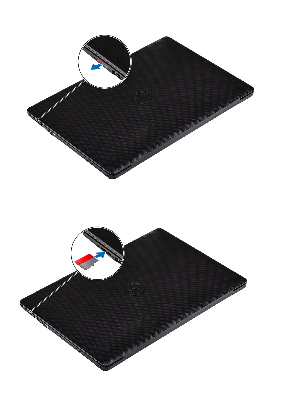
Installing the Micro Secure Digital card
Steps
Slide the micro secure digital into the slot until it clicks into place.
12
Scoaterea şi instalarea componentelor
Next steps
1. Follow the procedure in after working inside your computer
Ansamblul unității optice
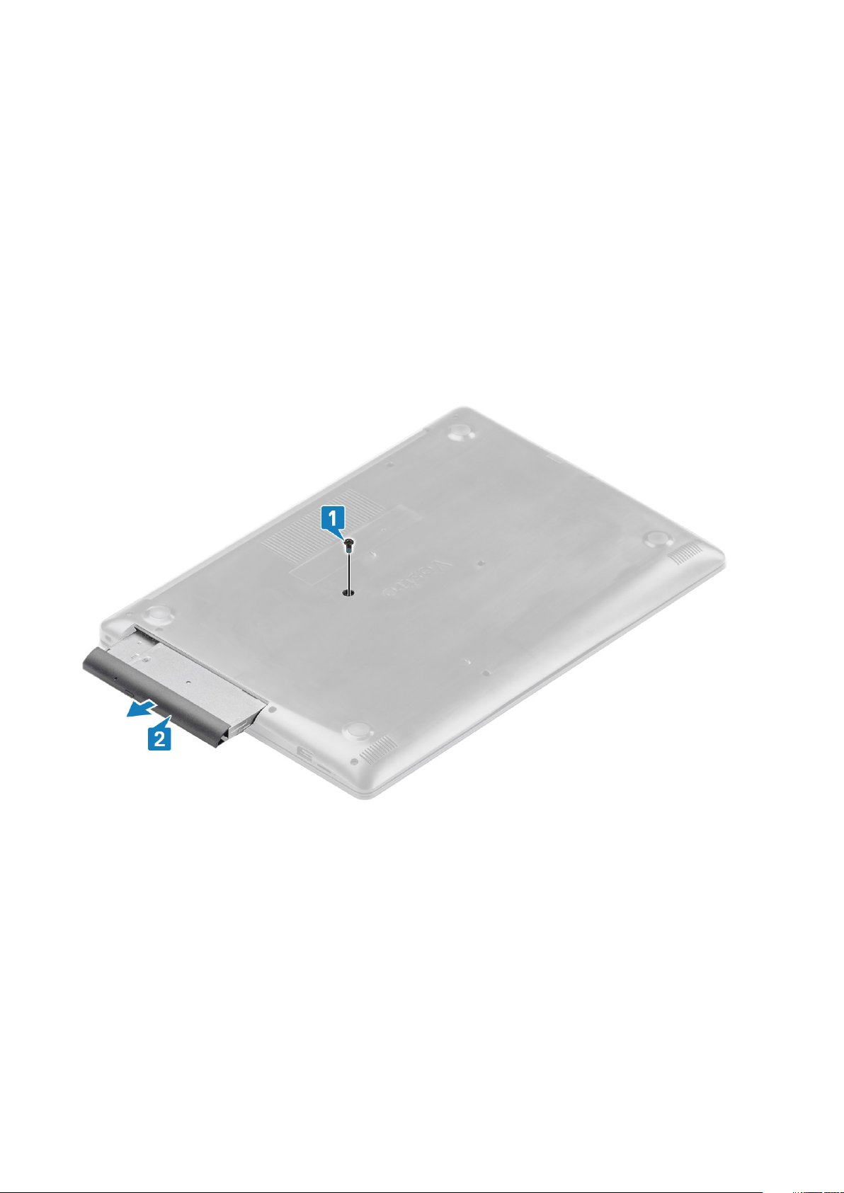
Removing the optical drive assembly
Prerequisites
1. Follow the procedure in before working inside your computer
2. Remove the micro SD card
Steps
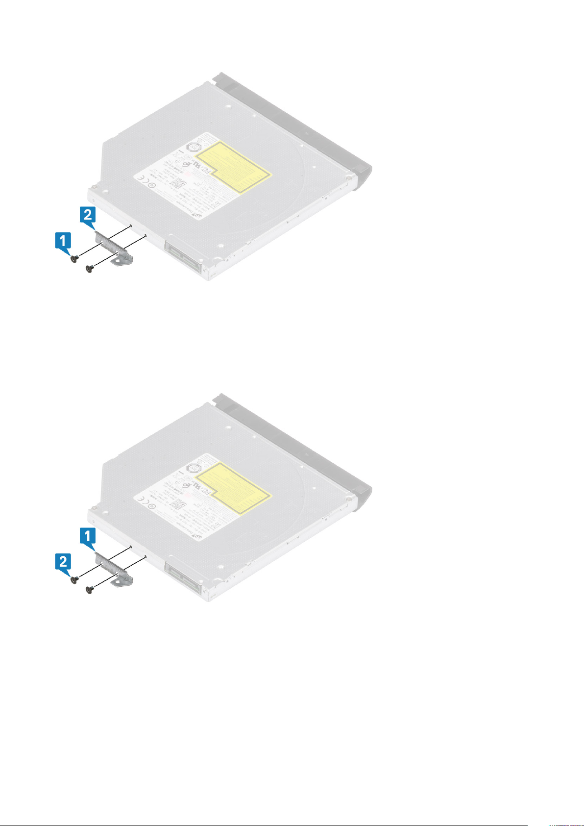
1. Remove the single (M2x4) screw that secures the optical drive to the system [1].
2. Slide the optical drive out of the computer [2].
3. Remove the two (M2x3) screws that secure the optical drive bracket to the optical drive [1].
4. Remove the optical drive bracket from the optical drive [2].
Scoaterea şi instalarea componentelor
13
Installing the optical drive assembly
Steps
1. Align the optical drive bracket to the screw holes on the optical drive [1].
2. Replace the two (M2x3) screws that secure the optical drive bracket to the optical drive [2].
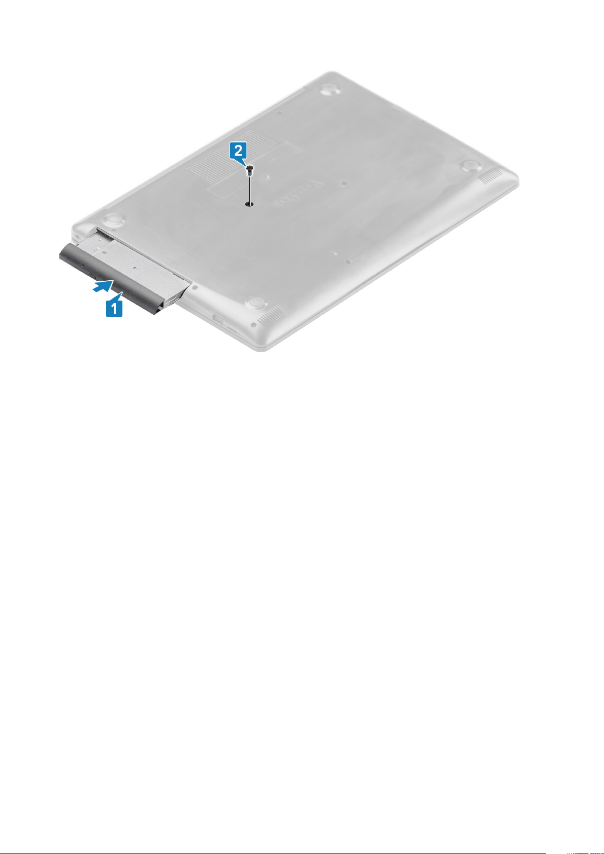
3. Insert the optical drive into the slot until it clicks into place [1].
4. Replace the single (M2x4) screw that secures the optical drive to the system [2].
14
Scoaterea şi instalarea componentelor
Next steps
1. Replace the micro SD card
2. Follow the procedure in after working inside your computer
Capacul bazei
Removing the base cover
Prerequisites
1. Follow the procedure in before working inside your computer
2. Remove the SD memory card
3. Remove the optical drive assembly
Steps
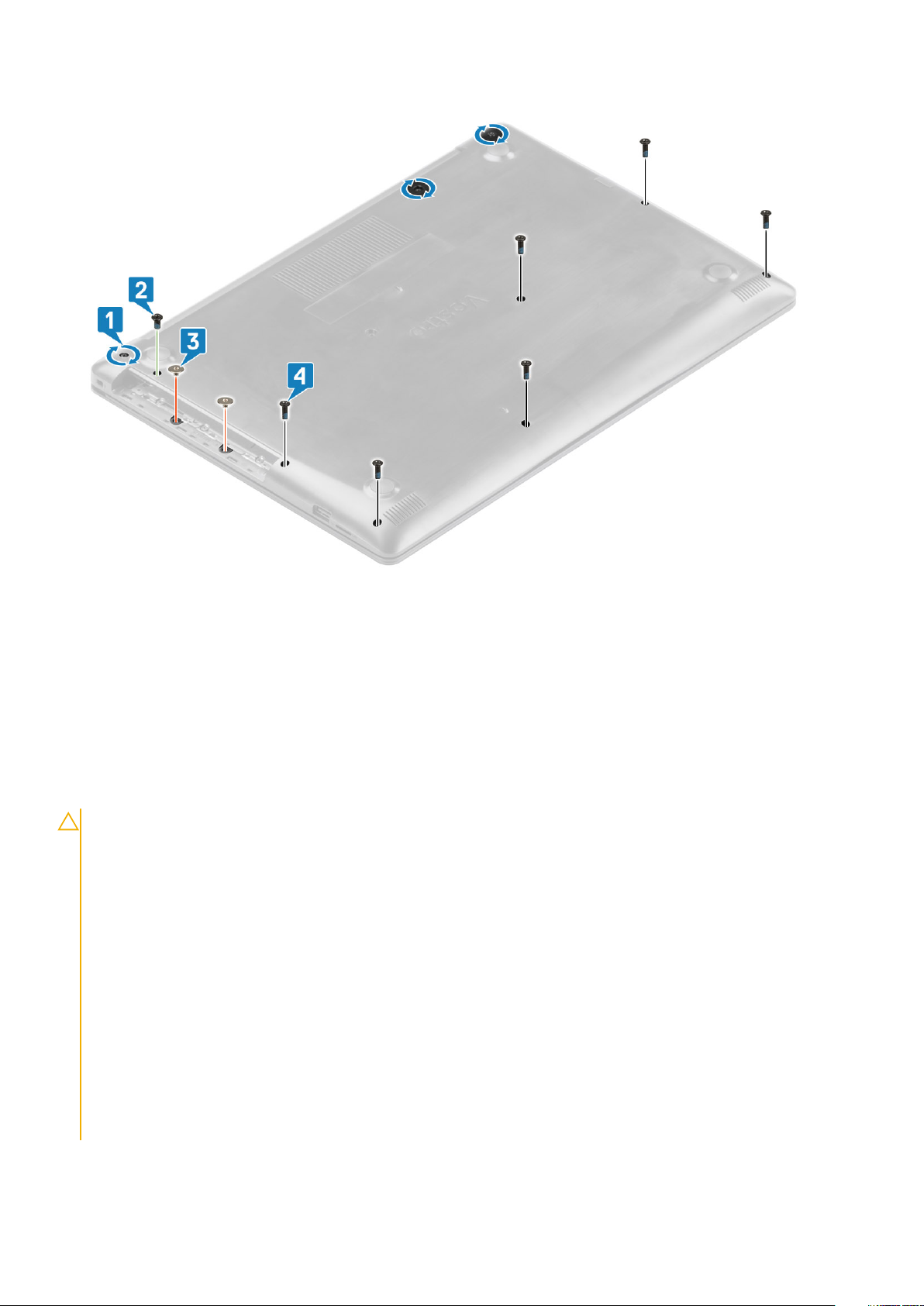
1. Loosen the three captive screws [1].
2. Remove the single (M2x4) screw, two (M2x2) screws, and six (M2.5x7) screws that secure the base cover to the palmrest and
keyboard assembly [2, 3, 4].
Scoaterea şi instalarea componentelor
15
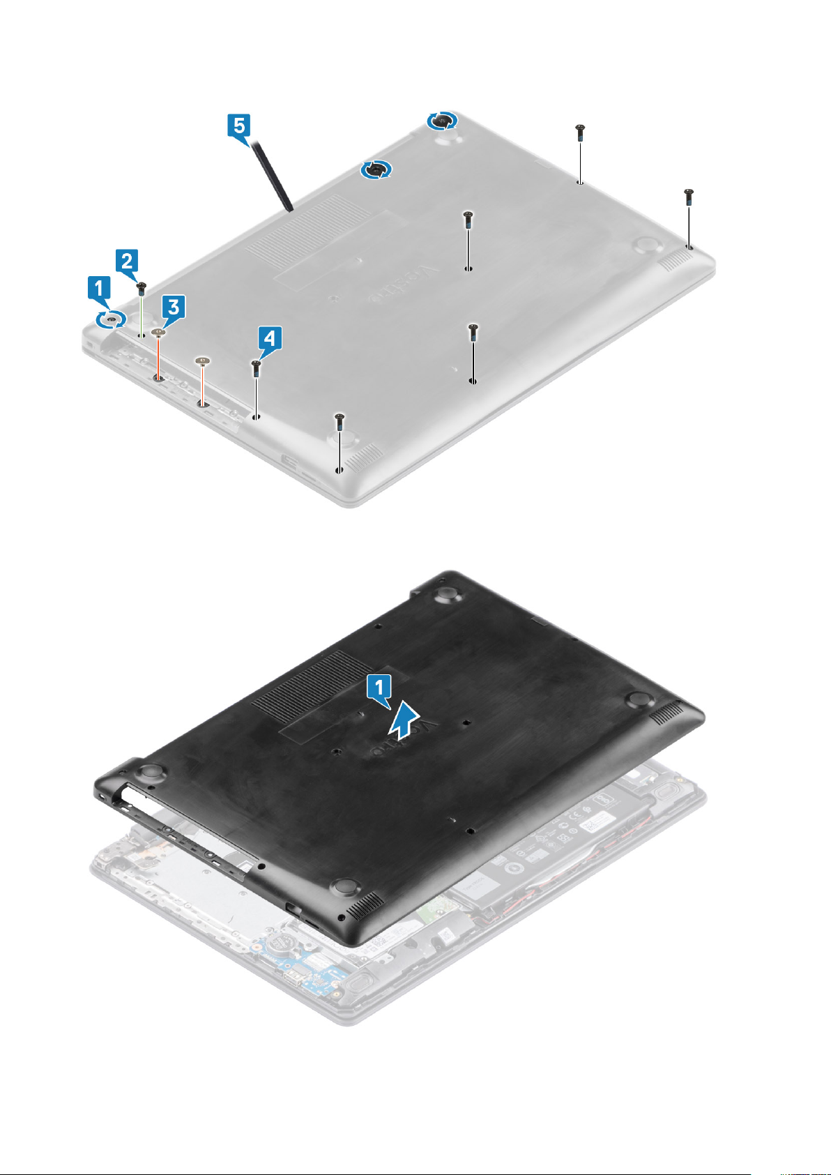
3. Use a prying tool and remove the base cover from the system [5].
4. Lift the left side of the base cover and remove it off the system [1].
16
Scoaterea şi instalarea componentelor
Installing the base cover
Steps
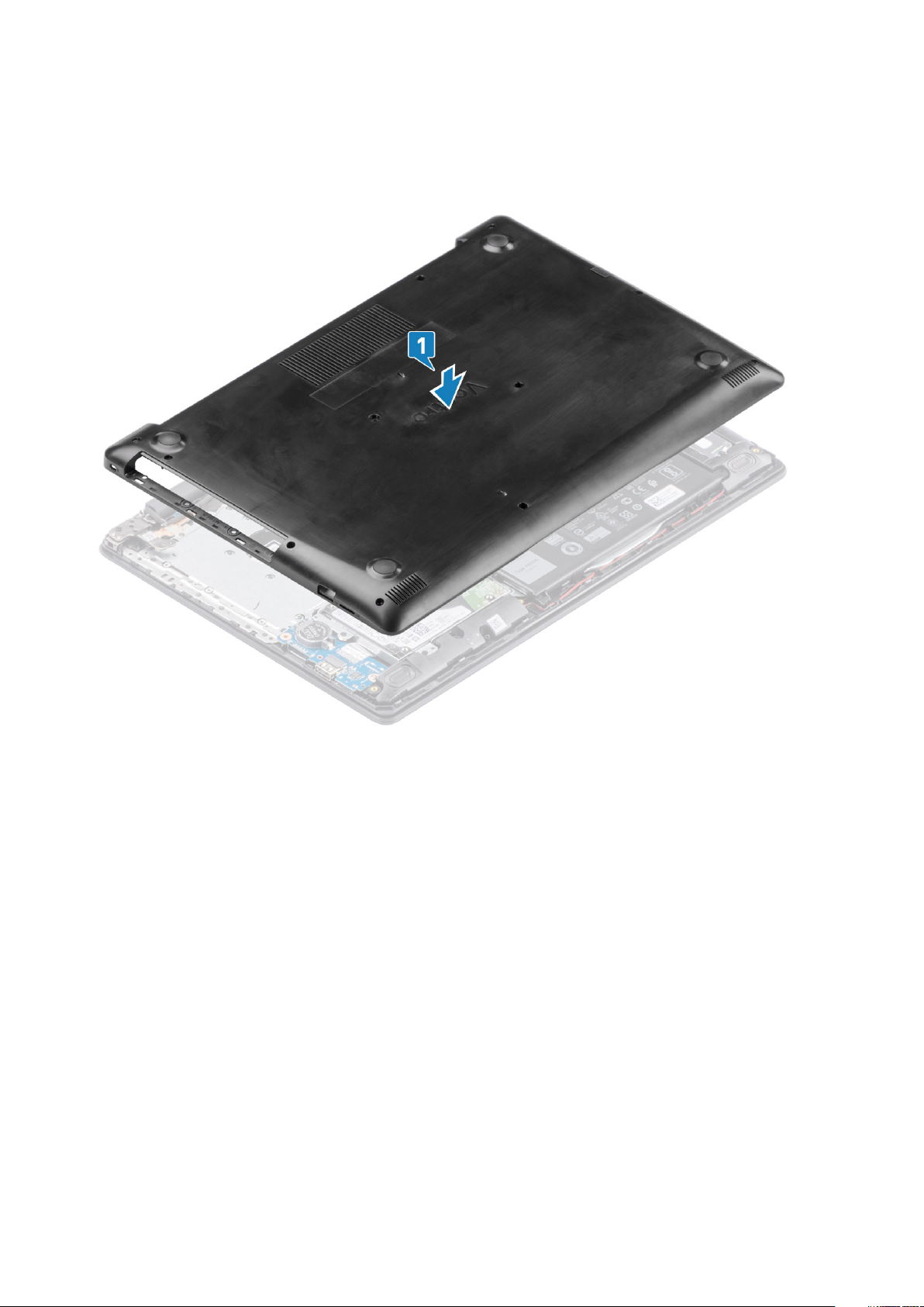
1. Replace the base cover on the palmrest and keyboard assembly [1].
2. Replace the two (M2x2) screws, and six (M2.5x7) screws that secure the base cover to the palmrest and keyboard assembly [3, 4].
Scoaterea şi instalarea componentelor
17
Next steps
1. Replace the optical drive assembly
2. Replace the SD memory card
3. Follow the procedure in after working inside your computer
Baterie
Lithium-ion battery precautions
CAUTION:
• Exercise caution when handling Lithium-ion batteries.
• Discharge the battery as much as possible before removing it from the system. This can be done by disconnecting
the AC adapter from the system to allow the battery to drain.
• Do not crush, drop, mutilate, or penetrate the battery with foreign objects.
• Do not expose the battery to high temperatures, or disassemble battery packs and cells.
• Do not apply pressure to the surface of the battery.
• Do not bend the battery.
• Do not use tools of any kind to pry on or against the battery.
• Ensure any screws during the servicing of this product are not lost or misplaced, to prevent accidental puncture or
damage to the battery and other system components.
• If the battery gets stuck inside your computer as a result of swelling, do not try to release it as puncturing, bending,
or crushing a lithium-ion battery can be dangerous. In such an instance, contact Dell technical support for
assistance. See www.dell.com/contactdell.
• Always purchase genuine batteries from www.dell.com or authorized Dell partners and resellers.
18 Scoaterea şi instalarea componentelor
Removing the battery
Prerequisites
1. Follow the procedure in before working inside your computer
2. Remove the SD memory card
3. Remove the optical drive assembly
4. Remove the base cover
Steps
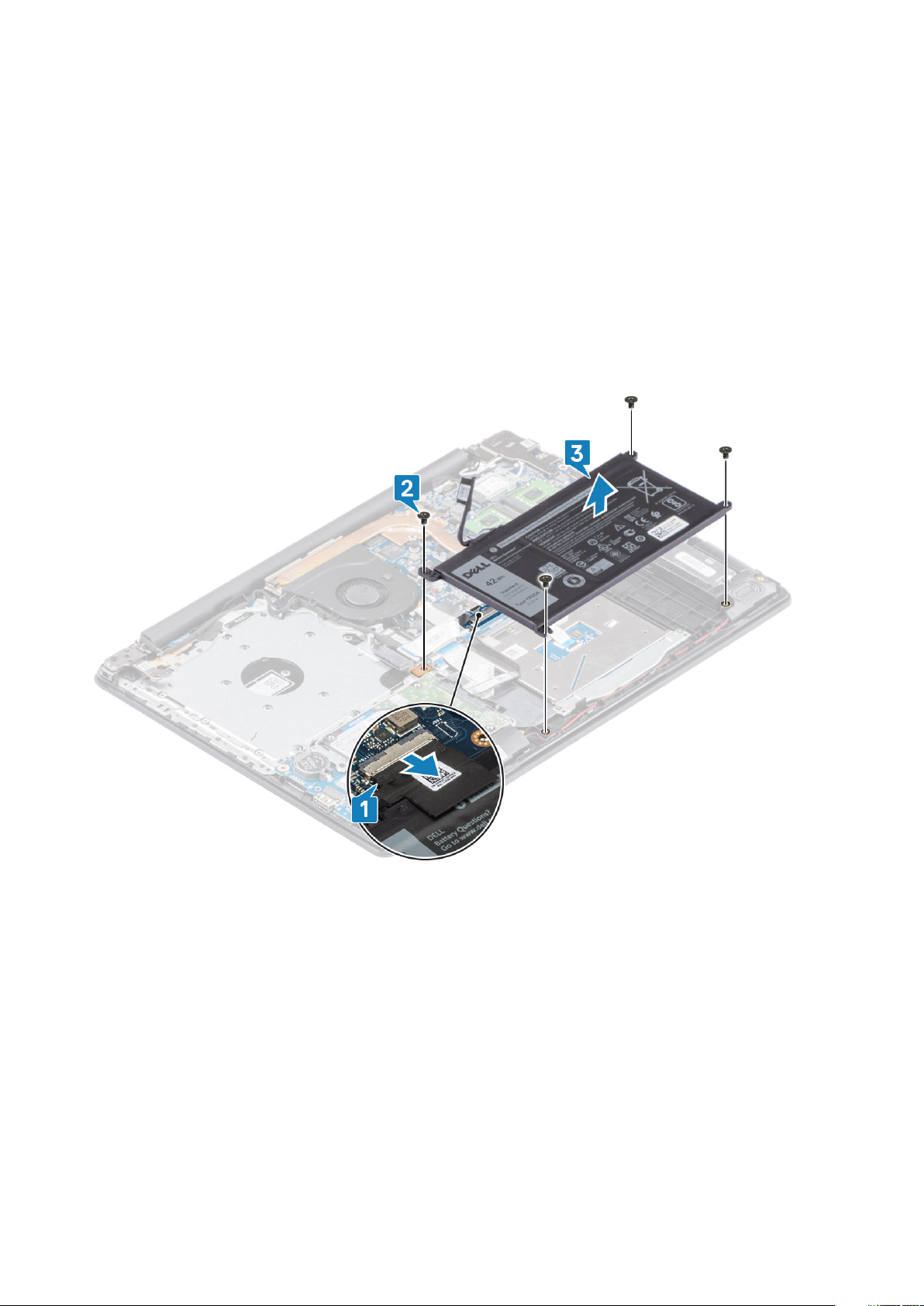
1. Disconnect the battery cable from the system board [1].
2. Remove the four (M2x3) screws that secure the battery to the palmrest and keyboard assembly [2].
3. Lift the battery off the palmrest and keyboard assembly [3].
Installing the battery
Steps
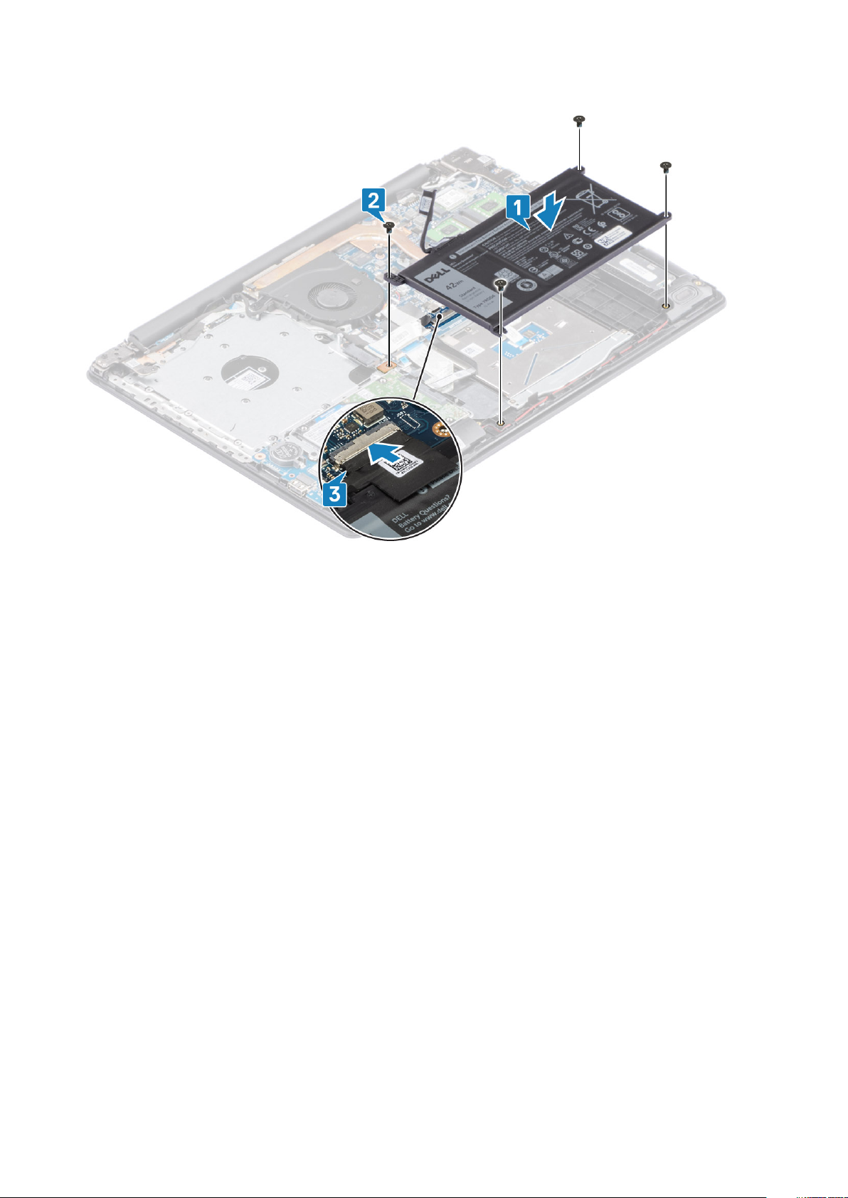
1. Align the screw holes on the battery with the screw holes on the palmrest and keyboard assembly [1].
2. Replace the four (M2x3) screws that secure the battery to the palmrest and keyboard assembly [2].
3. Connect the battery cable to the system board [3].
Scoaterea şi instalarea componentelor
19
Next steps
1. Replace the base cover
2. Replace the optical drive assembly
3. Replace the SD memory card
4. Follow the procedure in after working inside your computer
Modulele de memorie
Removing the memory module
Prerequisites
1. Follow the procedure in before working inside your computer
2. Remove the SD memory card
3. Remove the base cover
4. Disconnect the battery cable from the connector on the system board.
Steps
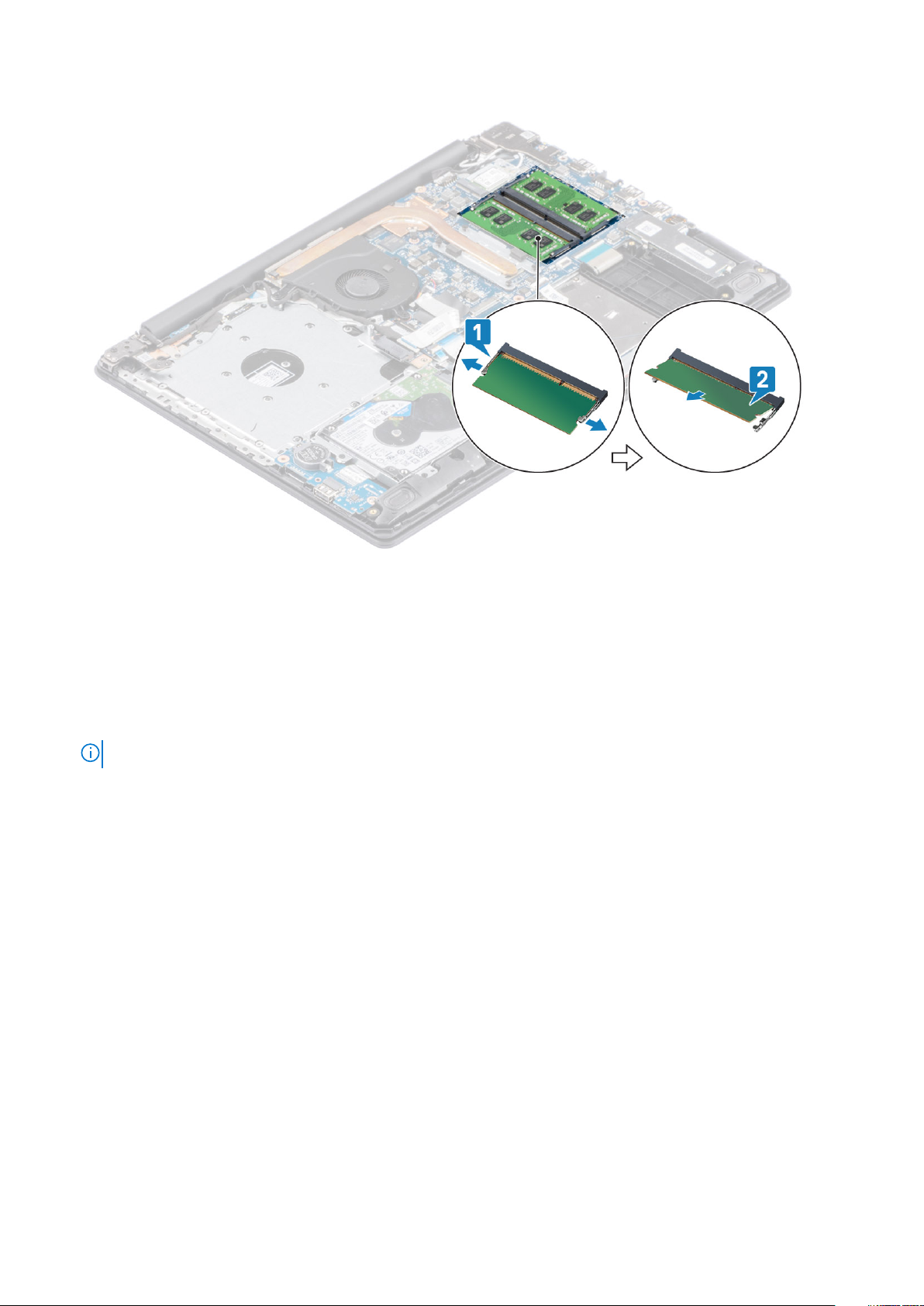
1. Pry the clips securing the memory module until the memory module pops-up [1].
2. Remove the memory module from the memory module slot [2].
20
Scoaterea şi instalarea componentelor
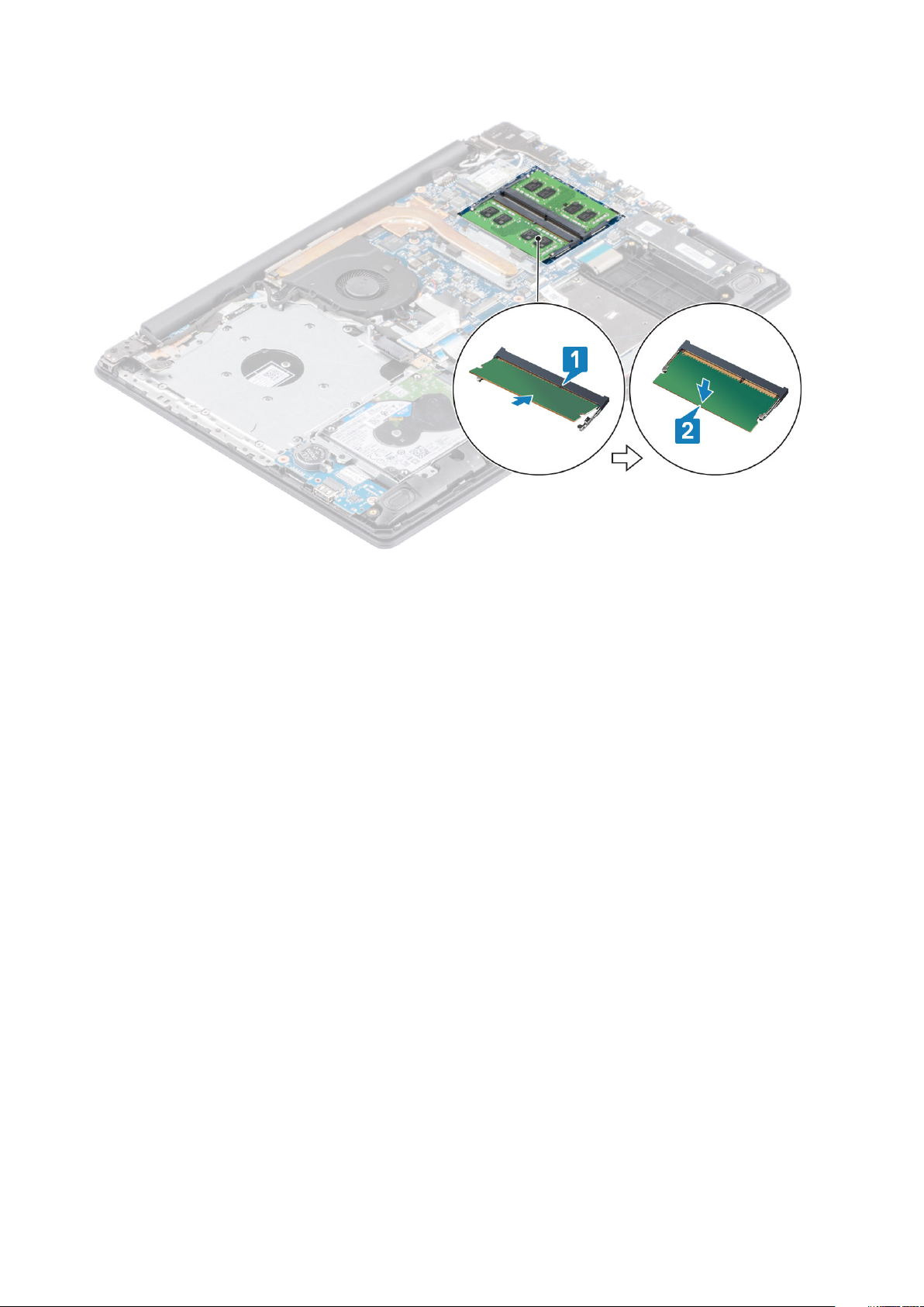
Installing the memory module
Steps
1. Align the notch on the memory module with the tab on the memory module slot and slide the memory module firmly into the slot at an
angle [1].
2. Press the memory module down until the clips secure it [2].
NOTE: If you do not hear the click, remove the memory module and reinstall it.
Scoaterea şi instalarea componentelor 21
Next steps
1. Connect the battery cable to the connector on the system board.
2. Replace the base cover
3. Replace the optical drive assembly
4. Replace the SD memory card
5. Follow the procedure in after working inside your computer
placa WLAN
Removing the WLAN card
Prerequisites
1. Follow the procedure in before working inside your computer
2. Remove the SD memory card
3. Remove the optical drive assembly
4. Remove the base cover
5. Disconnect the battery cable from the connector on the system board.
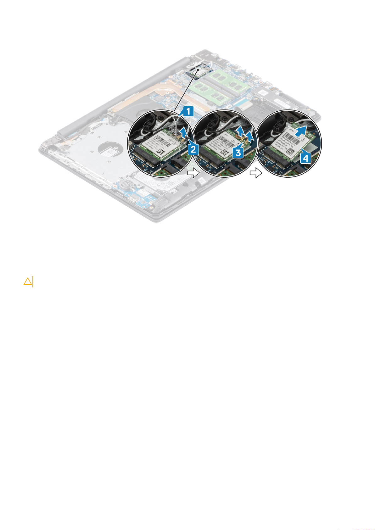
Steps
1. Remove the single (M2x3) screw that secures the WLAN card bracket to the system board [1].
2. Slide and remove the WLAN card bracket that secures the WLAN cables [2].
3. Disconnect the WLAN cables from the connectors on the WLAN card [3].
4. Lift the WLAN card away from the connector [4].
22
Scoaterea şi instalarea componentelor
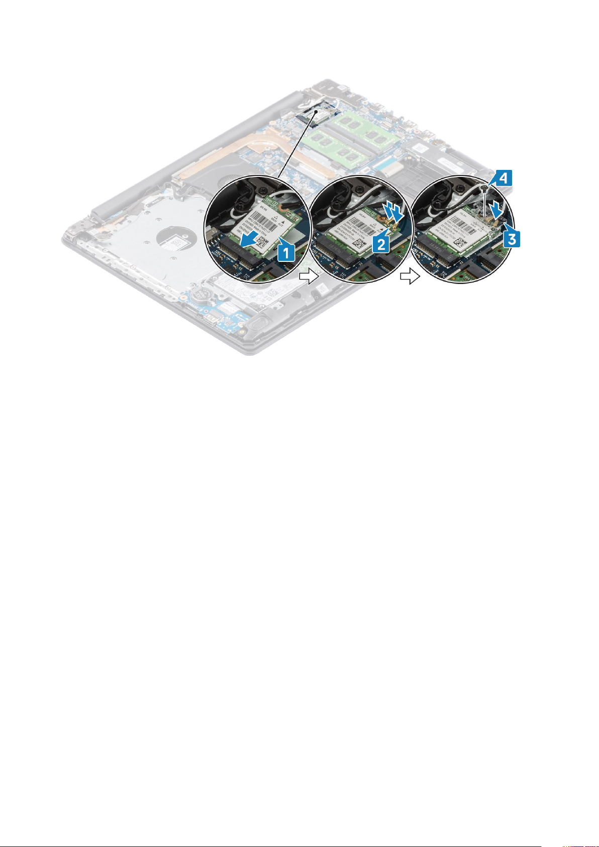
Installing the WLAN card
About this task
CAUTION: To avoid damage to the WLAN card, do not place any cables under it.
Steps
1. Replace the WLAN card into the connector on the system board [1].
2. Connect the WLAN cables to the connectors on the WLAN card [2].
3. Place the WLAN card bracket to secure the WLAN cables to the WLAN card [3].
4. Replace the single (M2x3) screw to secure the WLAN bracket to the WLAN card [4].
Scoaterea şi instalarea componentelor
23
Next steps
1. Connect the battery cable to the connector on the system board.
2. Replace the base cover
3. Replace the optical drive assembly
4. Replace the SD memory card
5. Follow the procedure in after working inside your computer
Solid-state drive/Intel Optane (Optional)
Removing the M.2 2230 Solid-state drive
Prerequisites
1. Follow the procedure in before working inside your computer
2. Remove the SD memory card
3. Remove the optical drive assembly
4. Remove the base cover
5. Disconnect the battery cable from the connector on the system board.
Steps
1. Loosen the captive screw that secures the thermal plate to the palmrest and keyboard assembly [1].
2. Remove the single (M2x3) screw that secures the thermal plate to the palmrest and keyboard assembly [2].
3. Slide and remove the thermal plate from the solid-state drive [3].
24
Scoaterea şi instalarea componentelor
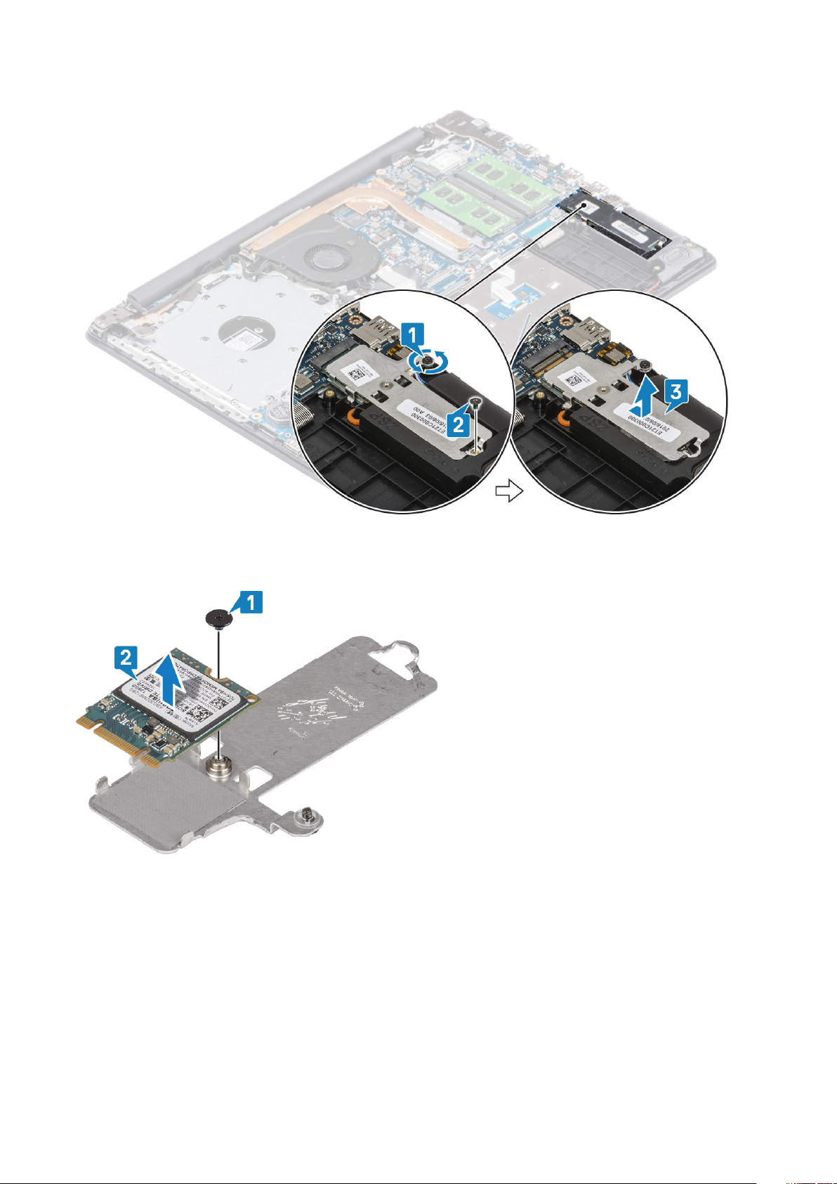
4. Turn the thermal plate over.
5. Remove the single (M2x2) screw that secures the solid-state drive to the thermal plate [1].
6. Lift the solid-state drive off the thermal plate [2].
Installing the M.2 2230 Solid-state drive
Steps
1. Place the solid-state drive into the thermal plate slot [1].
2. Replace the single (M2x2) screw that secures the solid-state drive to the thermal plate [2].
Scoaterea şi instalarea componentelor
25

3. Align the notch on the solid-state drive with the tab on the solid-state drive slot.
4. Slide and insert the tab of the solid-state drive into the solid-state drive slot [1,2].
5. Tighten the captive screw that secures the thermal plate to the palmrest and keyboard assembly [2].
6. Replace the single (M2x3) screw that secures the thermal plate to the palmrest and keyboard assembly [3].
Next steps
1. Connect the battery cable to the connector on the system board.
2. Replace the base cover
3. Replace the optical drive assembly
4. Replace the SD memory card
5. Follow the procedure in after working inside your computer
26
Scoaterea şi instalarea componentelor
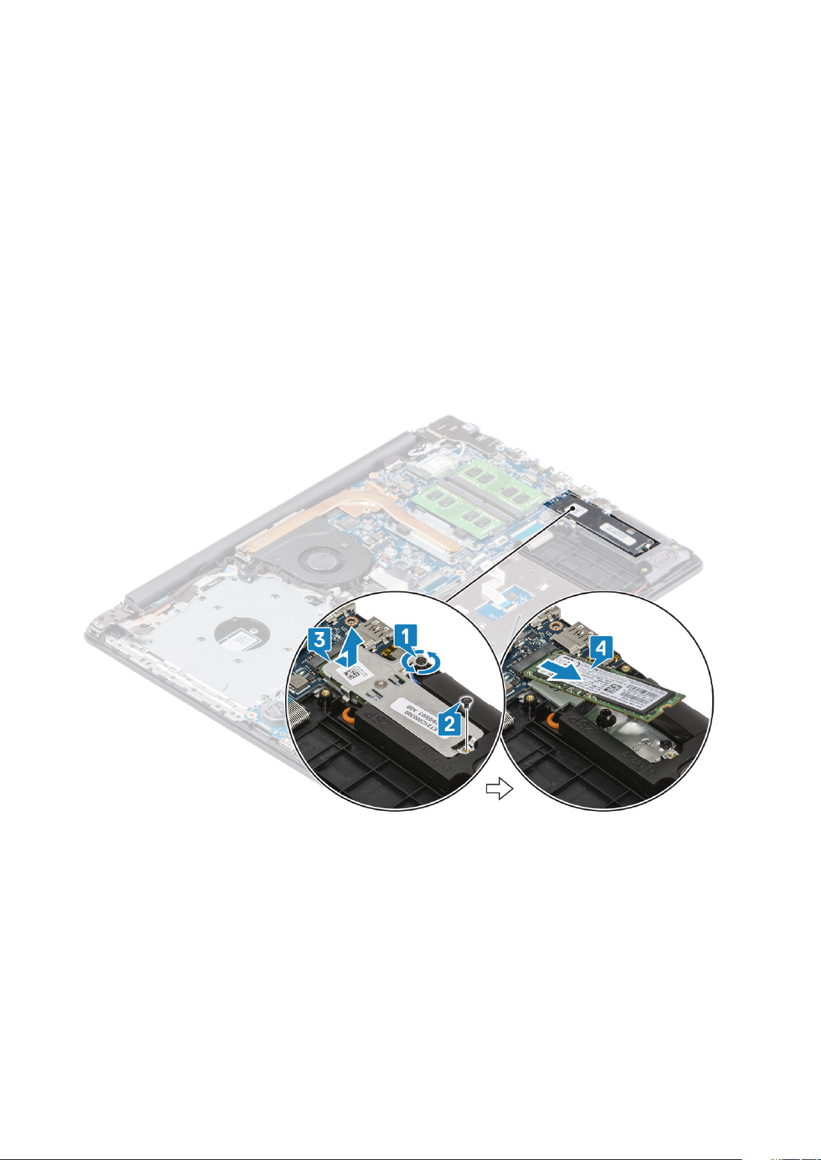
Removing the M.2 2280 Solid-state drive or Intel Optane memory - Optional
Prerequisites
1. Follow the procedure in before working inside your computer
2. Remove the SD memory card
3. Remove the optical drive assembly
4. Remove the base cover
5. Disconnect the battery cable from the connector on the system board.
Steps
1. Loosen the captive screw that secures the thermal plate to the palmrest and keyboard assembly [1].
2. Remove the single (M2x3) screw that secures the thermal plate to the palmrest and keyboard assembly [2].
3. Slide and remove the thermal plate from the solid-state drive/Intel Optane slot [3].
4. Slide and lift the solid-state drive/Intel Optane off the palmrest and keyboard assembly [4].
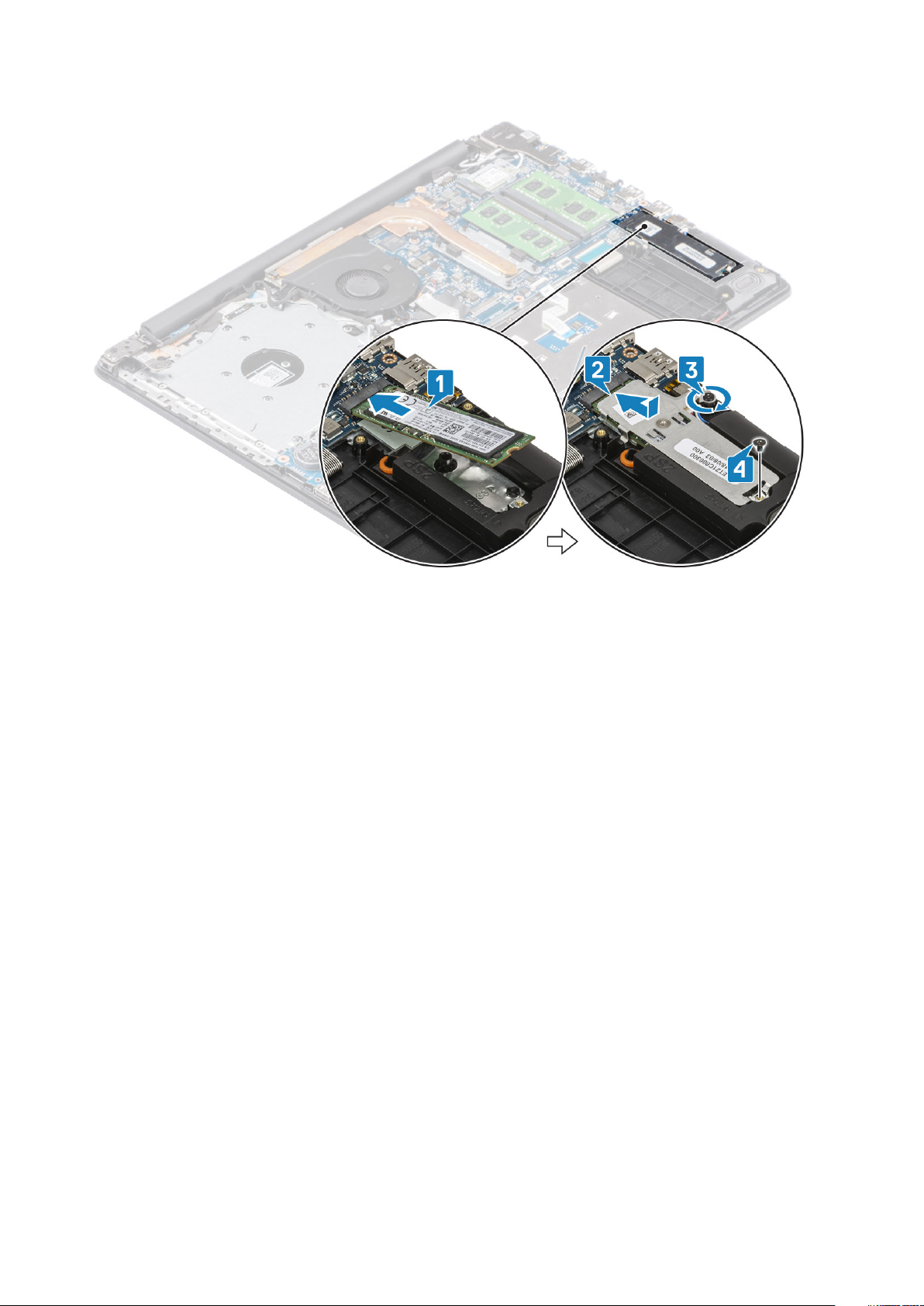
Installing the M.2 2280 Solid-state drive or Intel Optane memory - Optional
Steps
1. Slide and insert the tab of the solid-state drive/Intel Optane into the solid-state drive/Intel Optane slot [1, 2].
2. Align the thermal plate on the solid-state drive and tighten the captive screw that secures the thermal plate to the palmrest and
keyboard assembly [3].
3. Replace the single (M2x3) screw that secures the thermal plate to the palmrest and keyboard assembly [4].
Scoaterea şi instalarea componentelor
27
Next steps
1. Connect the battery cable to the connector on the system board.
2. Replace the base cover
3. Replace the optical drive assembly
4. Replace the SD memory card
5. Follow the procedure in after working inside your computer
Bateria rotundă
Removing the coin-cell
Prerequisites
1. Follow the procedure in before working inside your computer
2. Remove the SD memory card
3. Remove the optical drive assembly
4. Remove the base cover
5. Disconnect the battery cable from the connector on the system board.
Steps
1. Using a plastic scribe, gently pry the coin-cell battery out of the slot on the I/O board [1].
2. Remove the coin-cell battery away from the system [2].
28
Scoaterea şi instalarea componentelor
 Loading...