How it Works
Log In / Sign Up
Buy Points
How it Works
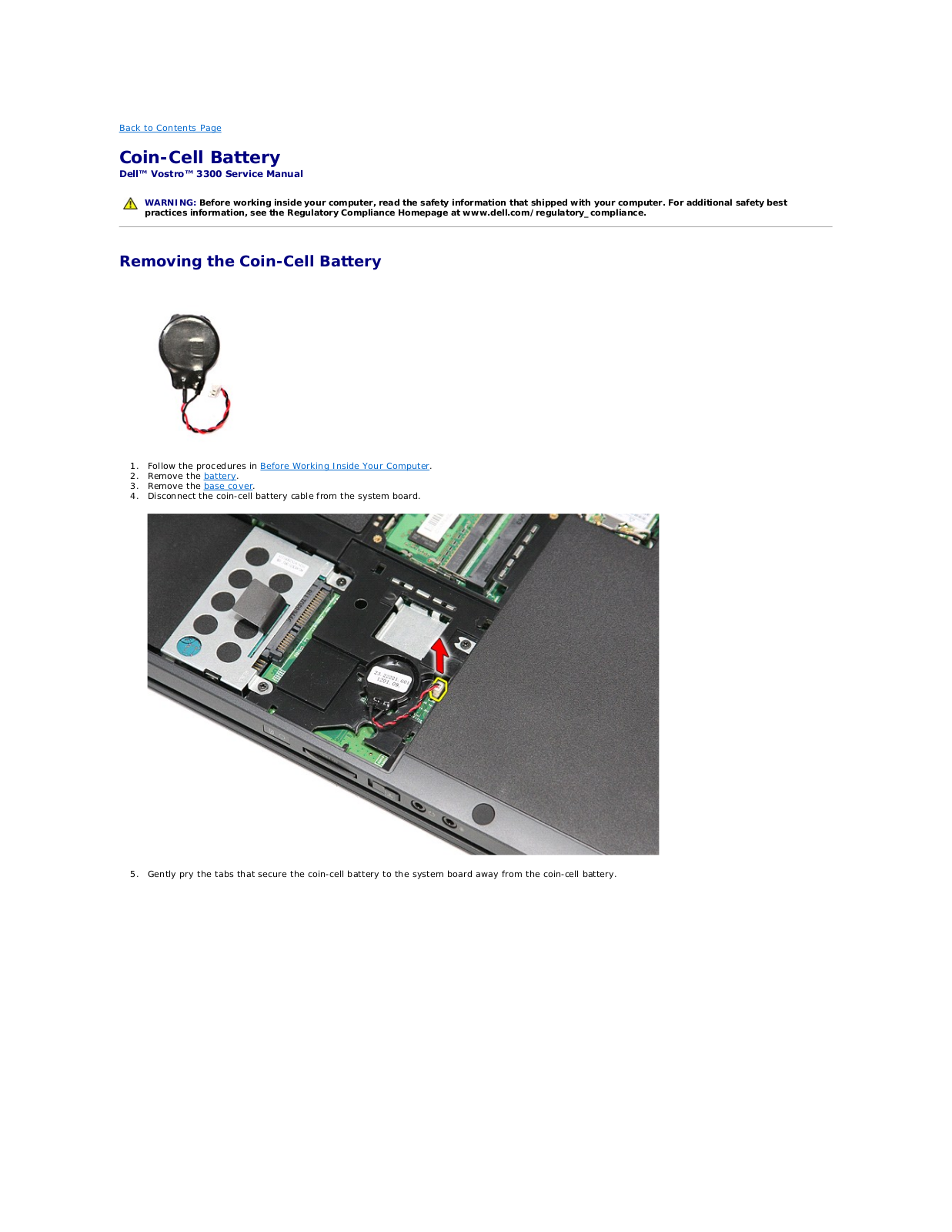
FAQ
Contact Us
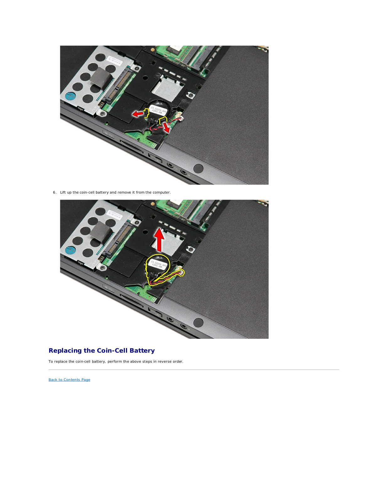
Questions and Suggestions
Users
Dell
Loading...
V
Vostro 1400
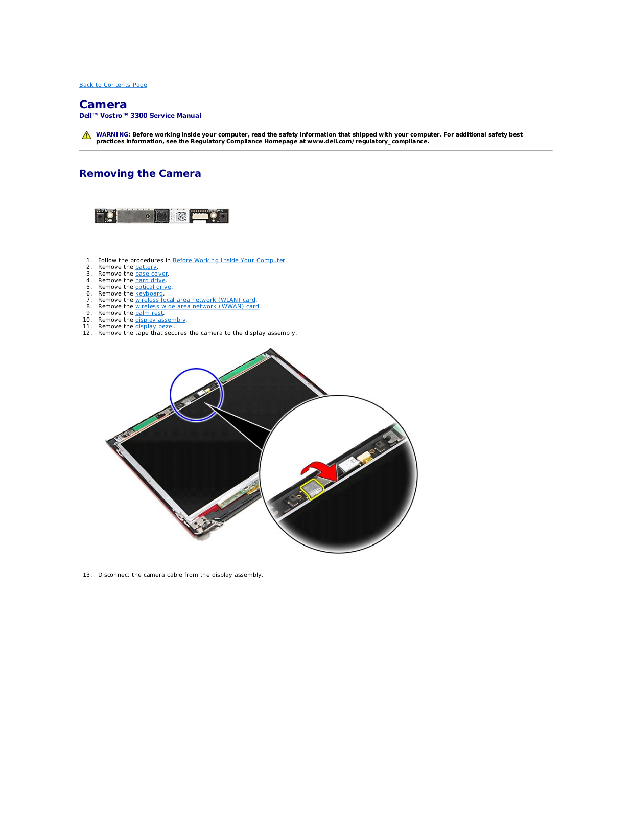
23
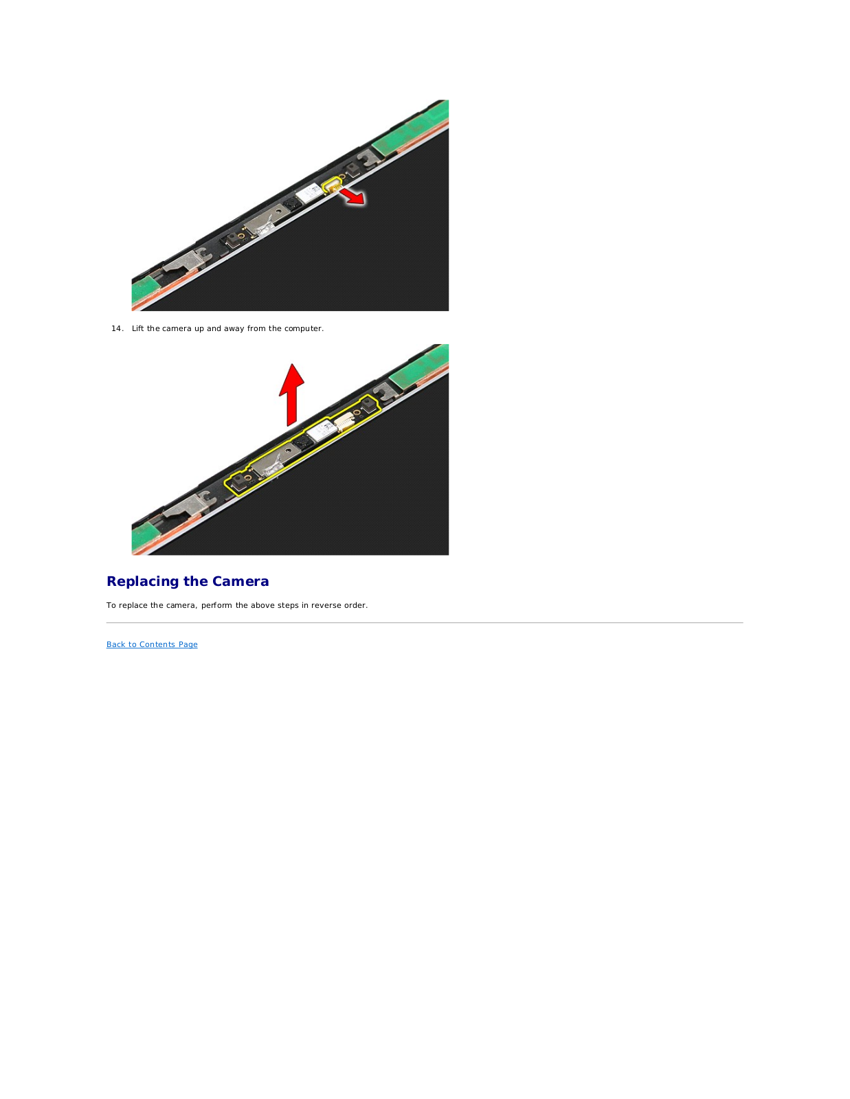
Vostro 1440
64
Vostro 15
4
Vostro 1500
30
Vostro 1510
108
Vostro 1520
61
Vostro 15 3000
2
Vostro 15–3558
3
Vostro 15-3559
Vostro 15 3562
2
Vostro 15 3565
18
Vostro 15 3568
41
Vostro 15-3578
Vostro 1540
63
Vostro 1550
63
Vostro 15 5000
Vostro 15 5568
43
Vostro 15 7570
24
Vostro 15 7580
38
Vostro 1700
24
Vostro 1710
111
Vostro 1720
60
Vostro 200
46
Vostro 200 Dcslf
Vostro 200 Mini-Tower
16
Vostro 200 Slim-Tower
17
Vostro 220
88
VOSTRO 220S
6
Vostro 230
58
Vostro 230s
58
Vostro 23 3340
Vostro 2420
53
Vostro 2421
23
Vostro 2510
4
Vostro 2520
56
VOSTRO 2521
23
Vostro 260
87
Vostro 260s
82
Vostro 260s Mini-Tower
29
Vostro 260s Slim-Tower
29
Vostro 270
60
Vostro 270s
33
Vostro 3052
3
Vostro 3055
4
Vostro 320
61
Vostro 3250
38
Vostro 3252
24
Vostro 3267
25
Vostro 3268
46
Vostro 330
6
Vostro 3300
63
Vostro 3340
4
Vostro 3350
54
Vostro 3360
58
Vostro 3400
6
Vostro 3400 (End of Life)
56
Vostro 3405
Vostro 3445
3
Vostro 3450
60
Vostro 3458
10
Vostro 3460
51
Vostro 3470
Vostro 3470-0908
Vostro 3470 SFF
Vostro 3471 SFF
Vostro 3478
34
Vostro 3481
Vostro 3490
Vostro 3500
7
Vostro 3500 (End of Life)
57
Vostro 3550
54
Vostro 3550 P16F
Vostro 3555
54
Vostro 3558
43
Vostro 3559
34
Vostro 3560
52
Vostro 3561
3
Vostro 3568
Vostro 3572
9
Vostro 3578
37
Vostro 3580
Vostro 3581
Vostro 3582
Vostro 3583
Vostro 3590
2
Vostro 3591
82
Vostro 360
62
Vostro 3650
38
Vostro 3653
14
Vostro 3660
Vostro 3667
2
Vostro 3667-0758
Vostro 3667-0765
Vostro 3667-8053
Vostro 3667 Desktop
16
Vostro 3667 MT
Vostro 3668
16
Vostro 3669
Vostro 3669 Desktop
11
Vostro 3670
55
Loading...
Loading...
Nothing found
Vostro 3300
User manual [de]
90 pgs
4.38 Mb
0
User Manual [in]
73 pgs
7.35 Mb
0
User Manual [th]
72 pgs
7.44 Mb
0
User Manual
72 pgs
7.35 Mb
0
User Manual [ro]
12 pgs
722.95 Kb
0
User Manual [po]
73 pgs
7.44 Mb
0
User Manual [pt]
12 pgs
687.06 Kb
1
User Manual [no]
73 pgs
7.39 Mb
0
User Manual [da]
12 pgs
665.57 Kb
0
User Manual [sv]
73 pgs
7.39 Mb
0
User guide [de]
16 pgs
728.86 Kb
0
User Manual [ar]
72 pgs
7.48 Mb
0
User Manual [si]
73 pgs
7.39 Mb
0
User Manual [nl]
73 pgs
7.36 Mb
0
User Manual [es]
73 pgs
7.4 Mb
0
User Manual [he]
72 pgs
7.43 Mb
0
User Manual [cs]
73 pgs
7.46 Mb
0
User Manual [zh]
72 pgs
7.82 Mb
0
User Manual [ko]
73 pgs
7.56 Mb
0
User Manual [fi]
73 pgs
7.39 Mb
0
User Manual [cr]
73 pgs
7.4 Mb
0
User Manual [gr]
73 pgs
7.43 Mb
0
User Manual [tr]
73 pgs
7.45 Mb
0
User Manual [hu]
73 pgs
7.42 Mb
0
User Manual [ja]
72 pgs
7.65 Mb
0
User Manual [sk]
73 pgs
7.44 Mb
0
User Manual [ru]
73 pgs
7.43 Mb
0
User Manual
4 pgs
165.38 Kb
0
User Manual [ru]
12 pgs
783.64 Kb
0
User Manual [zh]
12 pgs
962.07 Kb
0
User Manual [ko]
12 pgs
868.92 Kb
0
User Manual [hu]
12 pgs
722.95 Kb
0
User Manual [de]
73 pgs
7.4 Mb
0
User Manual
12 pgs
792.94 Kb
0
User Manual [in]
12 pgs
682.76 Kb
0
User Manual [zh]
4 pgs
164.33 Kb
0
User Manual [he]
12 pgs
851.07 Kb
0
User Manual [gr]
12 pgs
770.27 Kb
0
User Manual [tr]
12 pgs
674.04 Kb
0
User Manual [fi]
12 pgs
654.35 Kb
0
User Manual [pt]
73 pgs
7.4 Mb
0
User Manual [pt]
73 pgs
7.4 Mb
0
User Manual [in]
12 pgs
664.78 Kb
0
User Manual [cr]
12 pgs
761.66 Kb
0
User Manual [fr]
12 pgs
655.73 Kb
0
User Manual [da]
73 pgs
7.4 Mb
0
User Manual [de]
4 pgs
91.56 Kb
0
User Manual [cs]
12 pgs
790.26 Kb
0
User Manual [no]
12 pgs
653.62 Kb
0
User Manual [fr]
4 pgs
88.23 Kb
0
User Manual [zh]
72 pgs
7.67 Mb
0
User Manual [ja]
12 pgs
1.41 Mb
0
User Manual [th]
12 pgs
782.24 Kb
0
User Manual [ar]
12 pgs
778.5 Kb
0
User Manual [sv]
12 pgs
683.66 Kb
0
User Manual [ro]
73 pgs
7.42 Mb
0
User Manual [si]
12 pgs
771.71 Kb
0
User Manual [pt]
12 pgs
672.66 Kb
0
User Manual [nl]
12 pgs
673.29 Kb
0
User Manual [de]
12 pgs
660.09 Kb
0
User Manual [zh]
12 pgs
845.63 Kb
0
User Manual [sk]
12 pgs
680.61 Kb
0
User Manual [in]
73 pgs
7.37 Mb
0
Table of contents
Loading...
Dell Vostro 3300 User Manual
...
Dell User Manual
Download
Specifications and Main Features
Frequently Asked Questions
User Manual
Download
Loading...
+
50
hidden pages
Unhide
You need points to download manuals.
1 point = 1 manual.
You can buy points or you can get point for every manual you upload.
Buy points
Upload your manuals
 Loading...