

Page 1

Dell™ Vostro™ V130 Service Manual
Regulatory Model: Regulatory Model: P16S
Page 2

2
Page 3

Working on Your Computer
Before Working Inside Your Computer
Use the following safety guidelines to help protect your computer from potential damage and to help to ensure your
personal safety. Unless otherwise noted, each procedure included in this document assumes that the following
conditions exist:
• You have performed the steps in Working on Your Computer.
• You have read the safety information that shipped with your computer.
• A component can be replaced or--if purchased separately--installed by performing the removal procedure in
reverse order.
WARNING: Before working inside your computer, read the safety information that shipped with your computer. For
additional safety best practices information, see the Regulatory Compliance Homepage at www.dell.com/
regulatory_compliance.
CAUTION: Many repairs may only be done by a certified service technician. You should only perform
troubleshooting and simple repairs as authorized in your product documentation, or as directed by the online or
telephone service and support team. Damage due to servicing that is not authorized by Dell is not covered by your
warranty. Read and follow the safety instructions that came with the product.
CAUTION: To avoid electrostatic discharge, ground yourself by using a wrist grounding strap or by periodically
touching an unpainted metal surface, such as a connector on the back of the computer.
CAUTION: Handle components and cards with care. Do not touch the components or contacts on a card. Hold a
card by its edges or by its metal mounting bracket. Hold a component such as a processor by its edges, not by its
pins.
CAUTION: When you disconnect a cable, pull on its connector or on its pull-tab, not on the cable itself. Some
cables have connectors with locking tabs; if you are disconnecting this type of cable, press in on the locking tabs
before you disconnect the cable. As you pull connectors apart, keep them evenly aligned to avoid bending any
connector pins. Also, before you connect a cable, ensure that both connectors are correctly oriented and aligned.
NOTE: The color of your computer and certain components may appear differently than shown in this document.
To avoid damaging your computer, perform the following steps before you begin working inside the computer.
1. Ensure that your work surface is flat and clean to prevent the computer cover from being scratched.
2. Turn off your computer (see Turning Off Your Computer).
3. If the computer is connected to a docking device (docked) such as the optional Media Base or Battery Slice,
undock it.
CAUTION: To disconnect a network cable, first unplug the cable from your computer and then unplug the
cable from the network device.
4. Disconnect all network cables from the computer.
5. Disconnect your computer and all attached devices from their electrical outlets.
6. Close the display and turn the computer upside-down on a flat work surface.
NOTE: To avoid damaging the system board, you must remove the main battery before you service the
computer.
7. Remove the main battery (see Battery).
3
Page 4
8. Turn the computer top-side up.
9. Open the display.
10. Press the power button to ground the system board.
CAUTION: To guard against electrical shock, always unplug your computer from the electrical outlet before
opening the display.
CAUTION: Before touching anything inside your computer, ground yourself by touching an unpainted metal
surface, such as the metal at the back of the computer. While you work, periodically touch an unpainted metal
surface to dissipate static electricity, which could harm internal components.
11. Remove any installed ExpressCards or Smart Cards from the appropriate slots.
Recommended Tools
The procedures in this document may require the following tools:
• Small flat-blade screwdriver
• #0 Phillips screwdriver
• #1 Phillips screwdriver
• Small plastic scribe
• Flash BIOS update program CD
Turning Off Your Computer
CAUTION: To avoid losing data, save and close all open files and exit all open programs before you turn off your
computer.
1. Shut down the operating system:
– In Windows Vista™:
Click Start , then click the arrow in the lower-right corner of the Start menu as shown below, and then
click Shut Down.
– In Windows® XP:
Click Start → Turn Off Computer → Turn Off. The computer turns off after the operating system shutdown
process is complete.
2. Ensure that the computer and all attached devices are turned off. If your computer and attached devices did not
automatically turn off when you shut down your operating system, press and hold the power button for about 4
seconds to turn them off.
After Working Inside Your Computer
After you complete any replacement procedure, ensure you connect any external devices, cards, and cables before
turning on your computer.
CAUTION: To avoid damage to the computer, use only the battery designed for this particular Dell computer. Do not
use batteries designed for other Dell computers.
4
Page 5

1. Connect any external devices, such as a port replicator, battery slice, or media base, and replace any cards, such
as an ExpressCard.
2. Connect any telephone or network cables to your computer.
CAUTION: To connect a network cable, first plug the cable into the network device and then plug it into the
computer.
3. Replace the battery.
4. Connect your computer and all attached devices to their electrical outlets.
5. Turn on your computer.
5
Page 6

6
Page 7
Battery
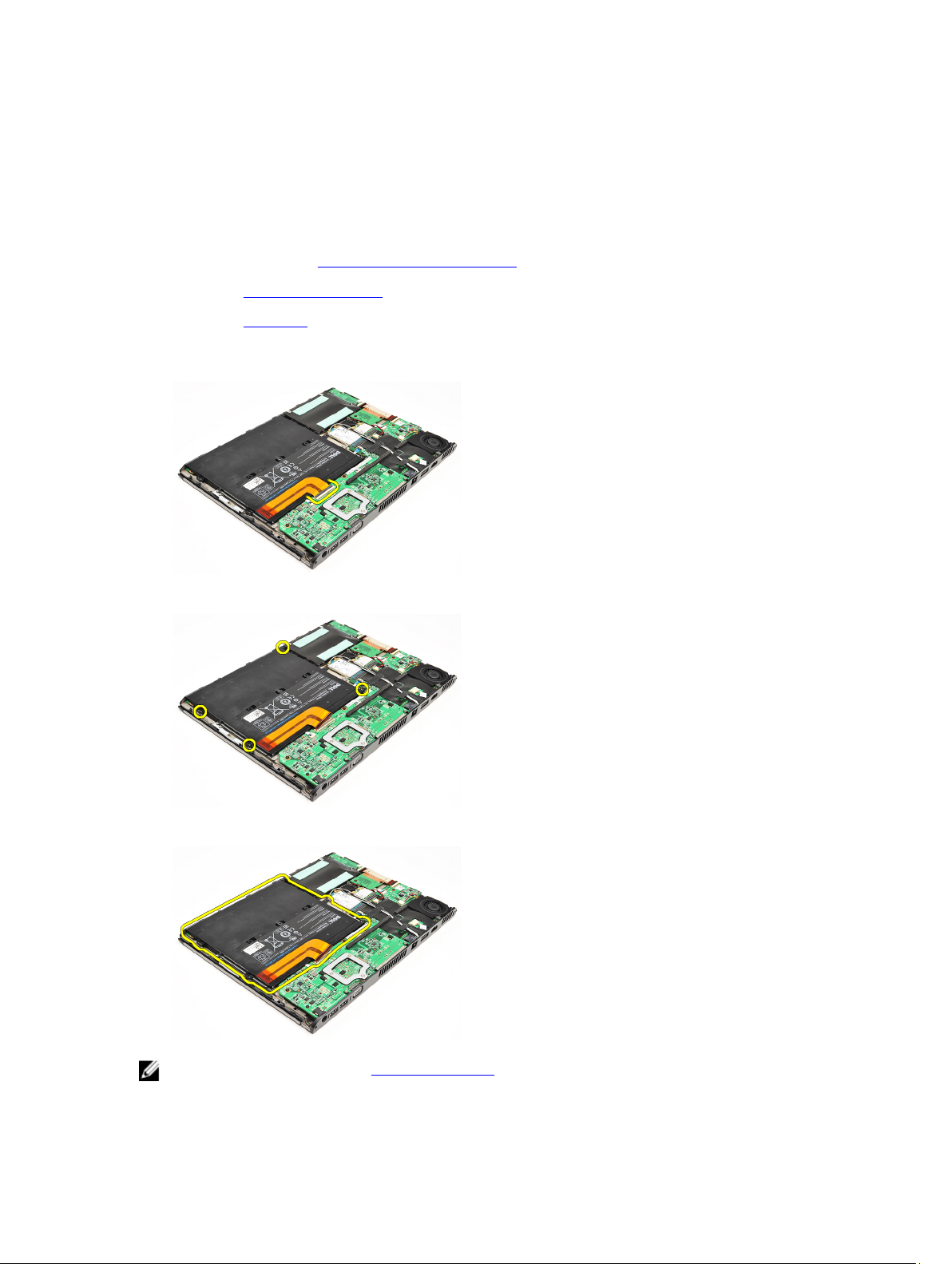
Removing The Battery
1. Follow the procedures in Before Working On Your Computer.
2. Remove the Secure Digital (SD) card.
3. Remove the base cover.
4. Lift the black cable-release clip to release the battery cable from the connector on the system board and
disconnect the battery cable.
5. Remove the screws that secure the battery to the computer.
6. Lift the battery up and away from the computer.
NOTE: To replace the battery, see Installing The Battery.
7
Page 8

Installing The Battery
NOTE: To remove or locate the battery, see Removing The Battery.
1. Place the battery into the battery bay.
2. Replace and tighten the screws that secure the battery to the computer.
3. Connect the battery cable to the system board and press down the cable-release clip to lock the battery cable.
4. Install the base cover.
5. Install the Secure Digital (SD) Card.
6. Follow the procedures in After working inside your computer.
8
Page 9

Secure Digital (SD) Card
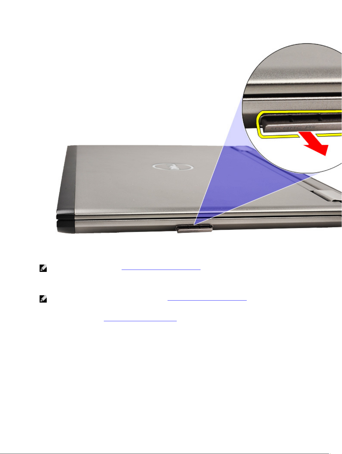
Removing The Secure Digital (SD) Card
1. Follow the procedures in Before Working On Your Computer.
2. Press in on the SD card to release the SD card from the computer.
Slide the SD card out of the computer.
3.
9
Page 10
NOTE: To install the SD card, see Installing The Secure Digital (SD) card.
Installing the Secure Digital (SD) Card
NOTE: To remove or locate the Secure Digital card, see Removing the Secure Digital (SD) card.
1. Slide the SD card into its slot until it clicks into place.
2. Follow the procedures in After working inside your computer.
10
Page 11

Base Cover
Removing The Base Cover
1. Follow the procedures in Before Working On Your Computer.
2. Remove the Secure Digital (SD) Card.
3. Remove the screws that secure the base cover to the computer.
4. Slide the base cover towards the front of the computer. Lift it up and away from the computer.
NOTE: To replace the base cover see, Installing The Base Cover.
Installing The Base Cover
NOTE: To remove or locate the base cover, see Removing The Base Cover .
1. Slide the base cover to align the screw holes correctly with the computer.
2. Tighten the screws that secure the base cover to the computer.
3. Install the Secure Digital (SD) card.
4. Follow the procedures in After Working Inside Your Computer.
11
Page 12

12
Page 13

Hard Drive and Audio Board
Removing The Hard Drive And Audio Board Assembly
1. Follow the procedures in Before Working On Your Computer.
2. Remove the Secure Digital (SD) card.
3. Remove the base cover.
4. Remove the battery.
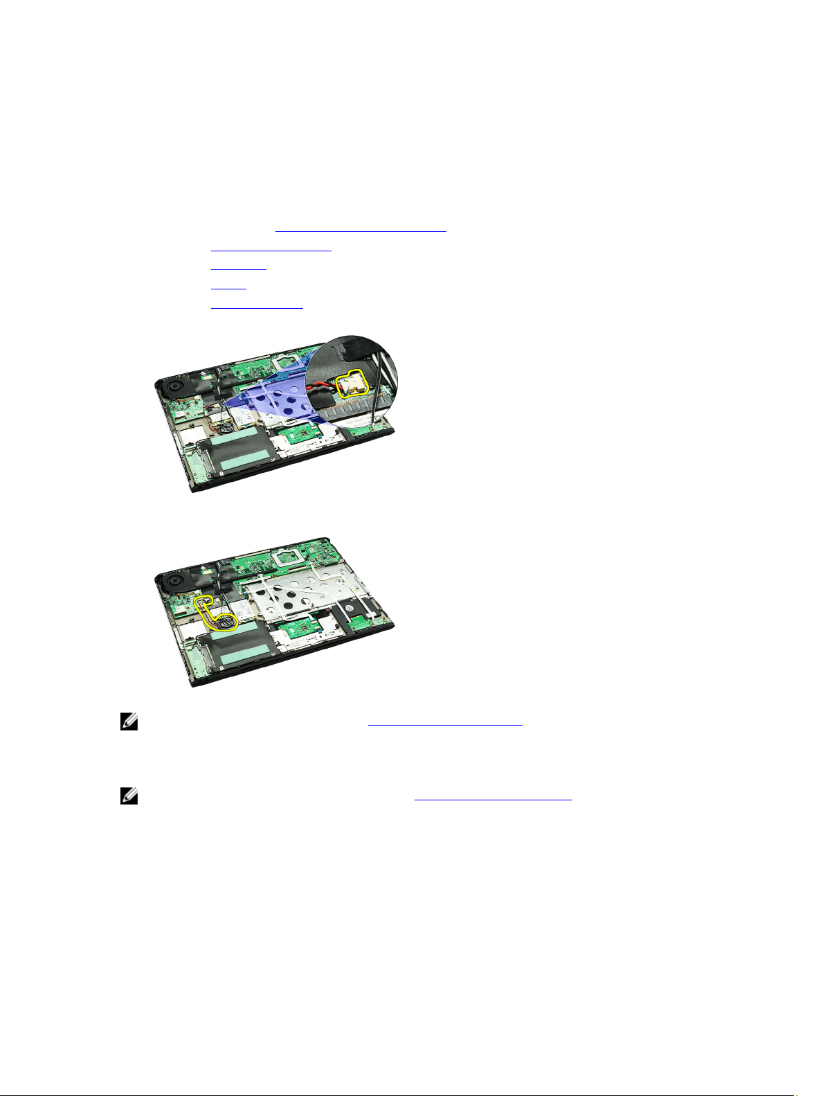
5. Disconnect the speaker and system board cables from the audio board.
6. Remove the screws that secure the audio board and the hard drive to the computer.
7. Lift and remove the hard drive and audio board assembly from the computer.
13
Page 14
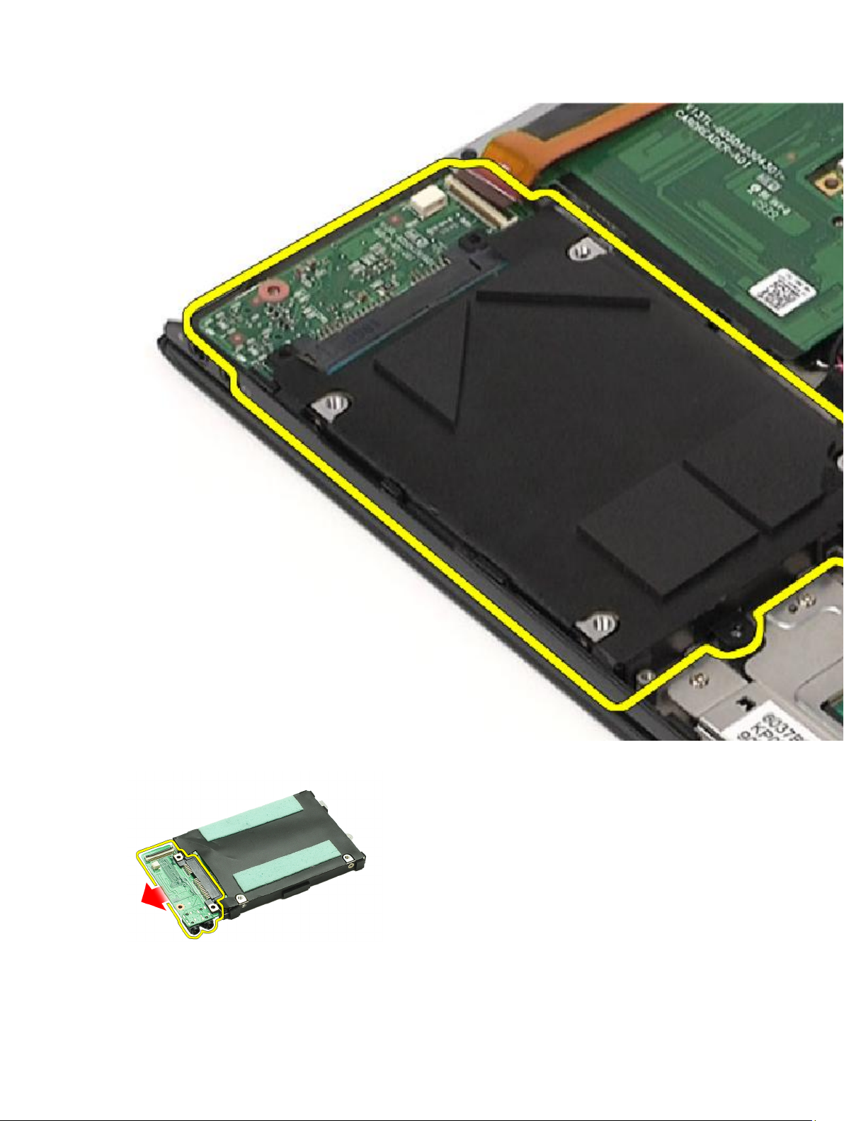
8. Slide the audio board from the hard drive.
9. Remove the screws that secure the hard-drive bracket to the hard drive.
14
Page 15

10. Remove the hard drive from the hard-drive bracket.
NOTE: To install the audio board and the hard drive, see Installing The Hard Drive And Audio Board Assembly.
Installing The Hard Drive And Audio Board Assembly
To remove or locate the hard drive and audio board, see Removing The Hard Drive And Audio Board Assembly.
1. Attach the hard-drive bracket to the hard drive.
2. Tighten the screws to secure the hard-drive bracket to the hard drive.
3. Connect the audio board to the hard drive.
4. Tighten the screws to secure the audio board and hard drive to the computer.
5. Connect the hard-drive data and speaker cable to the audio board.
6. Install the battery.
7. Install the base cover.
8. Install the Secure Digital (SD) card.
9. Follow the procedures in After working inside your computer.
15
Page 16

16
Page 17
Coin-Cell Battery
Removing The Coin-Cell Battery
1. Follow the procedures in Before Working on Your Computer.
2. Remove the Secure Digital (SD) card.
3. Remove the base cover.
4. Remove the battery.
5. Remove the card-reader board.
6. Disconnect the coin-cell battery cable from the system board.
7. Release and remove the coin-cell battery from the computer.
NOTE: To replace the coin-cell battery, see Installing The Coin-Cell Battery.
Installing The Coin-Cell Battery
NOTE: To remove or locate the coin-cell battery, see Removing The Coin-Cell Battery .
1. Place the coin-cell battery in its location.
17
Page 18

2. Connect the coin-cell battery cable to the system board.
3. Install the card-reader board.
4. Install the battery.
5. Install the base cover.
6. Install the secure digital (SD) card.
7. Follow the procedures in After working inside your computer.
18
Page 19
Wireless Local Area Network (WLAN) Card
Removing The Wireless Local Area Network (WLAN) Card
1. Follow the procedures in Before Working On Your Computer.
2. Remove the Secure Digital (SD) card.
3. Remove the base cover.
4. Remove the battery.
5. Disconnect the antenna cables from the WLAN card.
6. Remove the screw that secures the WLAN card to the computer.
7. Slide and remove the WLAN card out from its slot on the system board.
NOTE: To install the WLAN card, see Installing The Wireless Local Area Network (WLAN) Card.
19
Page 20

Installing The Wireless Local Area Network (WLAN) Card
NOTE: To remove or locate the WLAN card, see Removing The Wireless Local Area Network (WLAN) Card.
1. Insert the WLAN card into its connector at a 45–degree angle.
2. Replace and tighten the screw that secures the WLAN card to the computer.
3. Connect the black and white antenna cables to their respective connectors marked on the WLAN card.
4. Install the battery.
5. Install the base cover.
6. Install the Secure Digital (SD) card.
7. Follow the procedures in After Working Inside Your Computer.
20
Page 21

Palmrest and Display Assembly
Removing The Palmrest and Display Assembly
1. Follow the procedures in Before Working On Your Computer.
2. Remove the Secure Digital (SD) card.
3. Remove the base cover.
4. Remove the battery.
5. Remove the audio board and hard drive.
6. Remove the wireless local area network (WLAN) card.
7. Remove the wireless wide area network(WWAN) card.
8. Remove the LED cover.
9. Remove the memory.
10. Remove the keyboard.
11. Remove the card reader.
12. Remove the coin-cell battery.
13. Remove the thermal fan.
14. Remove the system board.
15. Remove the cloth tapes to release the antenna cables from the computer.
16. Release the antenna, camera and display cables from the computer.
17. Remove the screws to release the display assembly from the palmrest.
21
Page 22

18. Pull the cables out from the openings in the palmrest assembly to release the display assembly from the palmrest
assembly.
NOTE: To install the palmrest and display assembly, see Installing The Palmrest and Display Assembly
Installing The Palmrest and Display Assembly
NOTE: To remove or locate the system board, see Removing The Palmrest and Display Assembly.
1. Route all the cables from the display assembly into the openings in the palmrest assembly.
2. Align the palmrest and display assembly with the base of the computer.
3. Tighten the screws to secure the palmrest and display assembly to the base of the computer.
4. Route the antenna cables to their original position and use the cloth tape to secure them to the computer.
5. Install the system board.
6. Install the thermal fan.
7. Install the coin-cell battery.
8. Install the card reader.
9. Install the keyboard.
10. Install the memory.
11. Install the LED cover.
12. Install the wireless wide area network (WWAN) card.
13. Install the wireless local area network (WLAN) card.
14. Install the audio board and hard drive.
15. Install the battery.
16. Install the base cover.
17. Install the Secure Digital (SD) card.
18. Follow the procedures in After Working Inside Your Computer.
22
Page 23

Media Board
Removing The Media Board
1. Follow the procedures in Before Working On Your Computer.
2. Remove the LED cover.
3. Using a plastic scribe, pull the media board and remove it from the system board.
NOTE: To replace the system board see, Installing The Media Board.
Installing The Media Board
NOTE: To remove or locate the system board, see Removing The Media Board.
1. Replace and gently push the media board into its slot on the system board.
2. Install the LED cover.
3. Follow the procedures in After Working Inside Your Computer.
23
Page 24

24
Page 25

Speaker
Removing The Speaker
1. Follow the procedures in Before Working on Your Computer.
2. Remove the Secure Digital (SD) card.
3. Remove the base cover.
4. Remove the battery.
5. Remove the display-closure sensor.
6. Remove the audio board and the hard drive.
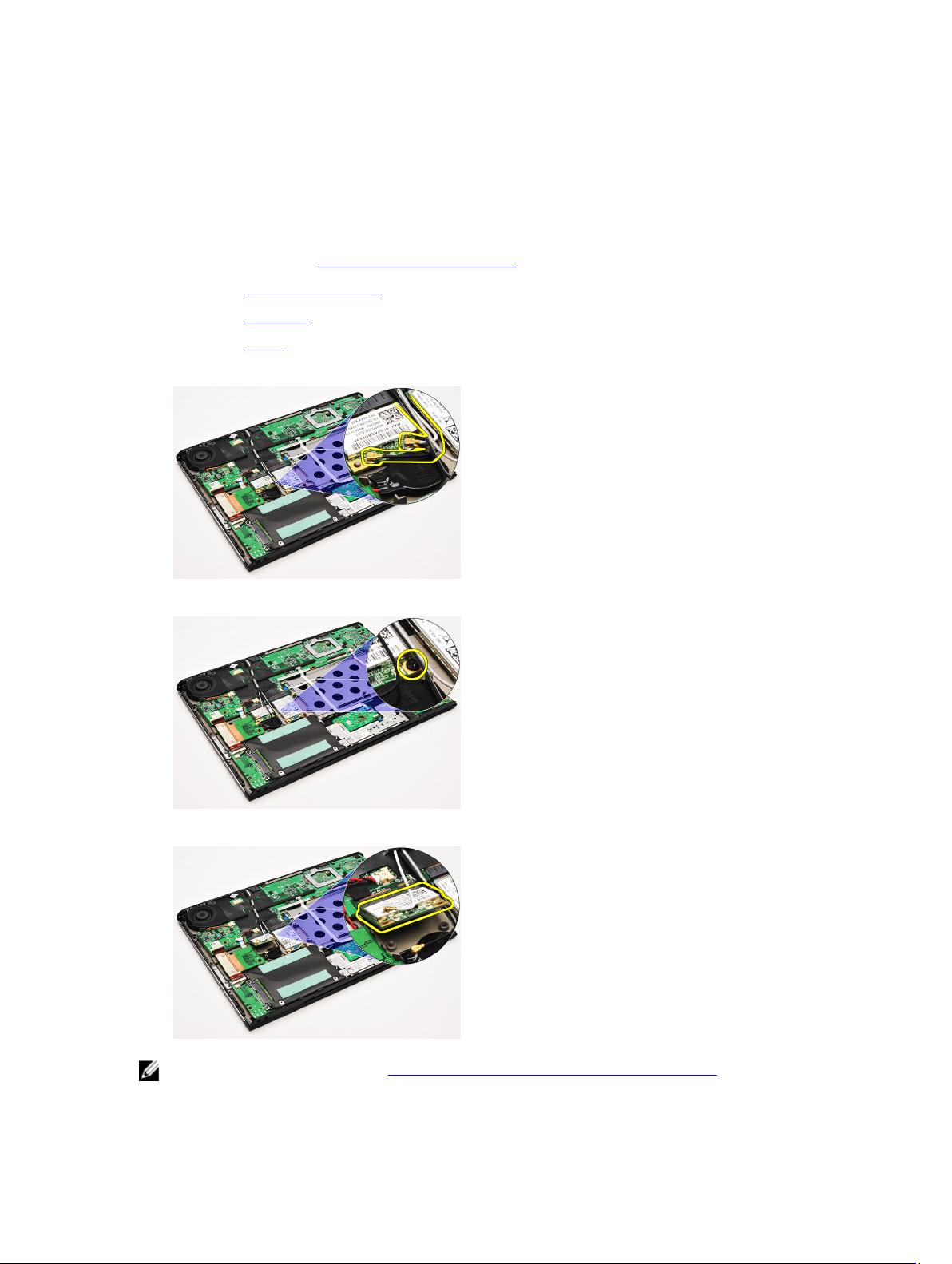
7. Remove the cloth tapes that secures the speaker cable to the computer.
8. Disconnect the touchpad cable from its connector on the system board.
9. Remove the screws that secure the speaker to the computer.
10. Disconnect the speaker cable from the audio board and release it from its routing guides on the computer.
25
Page 26

11. Remove the speaker from the computer.
NOTE: To replace the speaker, see Installing The Speaker.
Installing The Speaker
NOTE: To remove or locate the speaker, see Removing The Speaker.
1. Place the speaker into its slot on the computer.
2. Tighten the screws that secure the speaker to the computer.
3. Route the speaker cable back into its routing guide on the computer.
4. Secure the speaker cable to computer, using the cloth tapes provided.
5. Install the audio board and the hard drive.
6. Install the display closure sensor.
7. Install the battery.
8. Install the base cover.
9. Install the Secure Digital (SD) card.
10. Follow the procedures in After Working Inside Your Computer.
26
Page 27

Display Bezel
Removing the Display Bezel
1. Follow the procedures in Before Working On Your Computer.
2. Remove the Secure Digital (SD) card.
3. Remove the base cover.
4. Remove the battery.
5. Remove the wireless local area network (WLAN) card.
6. Remove the wireless wide area network (WWAN) card.
7. Remove the LED cover.
8. Remove the memory.
9. Remove the keyboard.
10. Remove the thermal fan.
11. Remove the system board.
12. Remove the palmrest assembly and display assembly.
13. Remove the screw covers from the display bezel.
14. Remove the screws that secure the display bezel to the display assembly.
15. Using a plastic scribe, pry under the display bezel to release it from the display assembly.
27
Page 28

16. Lift the display bezel and remove it from the display assembly.
28
Page 29

NOTE: To install the display bezel, see Installing The Display Bezel.
Installing The Display Bezel
NOTE: To remove or locate the display bezel, see Removing The Display Bezel.
1. Align the display bezel with the display assembly and gently snap it into place.
2. Replace and tighten the screws to secure the display bezel to the display assembly.
3. Replace the screw covers.
29
Page 30

4. Install the palmrest assembly and display assembly.
5. Install the system board.
6. Install the thermal fan.
7. Install the keyboard.
8. Install the memory.
9. Install the LED cover.
10. Install the wireless wide area network (WWAN) card.
11. Install the wireless local area network (WLAN) card.
12. Install the battery.
13. Install the base cover.
14. Install the secure digital (SD) Card.
15. Follow the procedures in After Working Inside Your Computer.
30
Page 31

Camera
Removing the Camera
1. Follow the procedures in Before Working on Your Computer.
2. Remove the Secure Digital (SD) card.
3. Remove the base cover.
4. Remove the battery.
5. Remove the display bezel.
6. Disconnect the camera cable from the camera module.
7. Using a plastic scribe, pry the camera to release it from the display back cover.
NOTE: To replace the camera, see Installing The Camera.
Installing the Camera
NOTE: To remove or locate the camera, see Removing The camera .
1. Connect the camera cable to the camera.
2. Secure the camera to the display cover.
3. Replace the display bezel.
4. Replace the battery.
5. Replace the base cover.
6. Replace the Secure Digital (SD) card.
31
Page 32

7. Follow the procedures in After working inside your computer.
32
Page 33

Thermal Fan
Removing The Thermal Fan
1. Follow the procedures in Before Working On Your Computer.
2. Remove the Secure Digital (SD) card.
3. Remove the base cover.
4. Remove the battery.
5. Remove the audio board and the hard drive.
6. Remove the wireless local area network (WLAN) card.
7. Remove the wireless wide area network (WWAN) card.
8. Remove the LED cover.
9. Remove the memory.
10. Remove the keyboard.
11. Remove the card reader board.
12. Remove the coin cell battery.
13. Remove the system board .
14. Remove the screw that secures the thermal fan to the computer.
15. Lift the fan up and away from the computer.
NOTE: To install the thermal fan, see Installing The Thermal Fan.
33
Page 34

Installing The Thermal Fan
NOTE: To remove or locate the heat sink and fan assembly, see Removing the Thermal Fan.
1. Place the fan into its slot on the computer.
2. Replace and tighten the screw to secure the fan to the computer.
3. Connect the thermal fan cable to the system board.
4. Install the system board.
5. Install the coin cell battery.
6. Install the card-reader board.
7. Install the keyboard.
8. Install the memory.
9. Install the LED cover.
10. Install the wireless wide area network (WWAN) card.
11. Install the wireless local area network (WLAN) card.
12. Install the audio board and the hard drive.
13. Install the battery.
14. Install the base cover.
15. Install the Secure Digital (SD) card.
16. Follow the procedures in After Working Inside Your Computer.
34
Page 35

System Board
Removing The System Board
1. Follow the procedures in Before Working On Your Computer.
2. Remove the Secure Digital (SD) card.
3. Remove the base cover.
4. Remove the battery.
5. Remove the wireless local area network (WLAN) card.
6. Remove the wireless wide area network (WWAN) card.
7. Remove the LED cover.
8. Remove the memory.
9. Remove the keyboard.
10. Pull the blue tab to disconnect the display cable from the system board.
11. Turn the computer over and remove the cloth tapes to release the antenna cables from the computer.
12. Remove the antenna cables gently.
35
Page 36

13. Disconnect the camera, thermal fan, coin-cell battery, hard drive, SD card reader, SIM card reader, LED board and
touch pad flex cables from the system board.
14. Remove the screws that secures the system board to the computer.
15. Lift the system board up and away from the computer.
NOTE: To replace the system board see, Installing The System Board.
36
Page 37

Installing The System Board
NOTE: To remove or locate the system board, see Removing The System Board.
1. Place the system board in its location on the base of the computer.
2. Tighten the screws that secures the system board to the computer.
3. Connect the camera cable , thermal fan cable, coin-cell battery cable, hard disk cable, SD card reader cable, SIM
card reader cable, touch pad flex cable, and LED board cable to the system board.
4. Replace and guide the antenna cables back through the cloth tapes to its original positions.
5. Turn the computer over and connect the display cable to the computer.
6. Install the keyboard.
7. Install the memory.
8. Install the LED cover.
9. Install the wireless wide area network (WWAN) card.
10. Install the wireless local area network (WLAN) card.
11. Install the battery.
12. Install the base cover.
13. Install the Secure Digital (SD) card.
14. Follow the procedures in After Working Inside Your Computer.
37
Page 38

38
Page 39

Subscriber Identity Module (SIM) Card
Removing The Subscriber Identity Module (SIM) Card
1. Follow the procedures in Before Working On Your Computer.
2. Remove the Secure Digital (SD) card.
3. Remove the base cover.
4. Remove the battery.
5. Insert a paper clip into the small hole on the SIM card holder to release the SIM card holder out of its slot.
6. Slide the SIM card holder out from the system.
7. Remove the SIM card from the SIM card holder.
NOTE: To replace the SIM card see Installing The Subscriber Identity Module (SIM) Card.
39
Page 40

Installing the Subscriber Identity Module (SIM) Card
NOTE: To remove or locate the SIM card, see Removing The Subscriber Identity Module (SIM) Card.
1. Place the SIM card on the SIM card holder.
2. Slide the SIM card holder together with the SIM card into its compartment until you hear a click.
3. Follow the procedures in After Working Inside Your Computer.
40
Page 41

Memory
Removing The Memory
1. Follow the procedures in Before Working On Your Computer
2. Remove the LED cover.
3. Use your fingertips to spread apart the securing clips on each end of the memory module connector until the
memory module pops up.
4. Remove the memory module from its connector on the system board by drawing the module from the system board
at 45-degree angle.
NOTE: To replace the memory, see Installing The Memory.
Installing The Memory
NOTE: To remove or locate the memory, see Removing the Memory.
1. Push the memory module into the memory slot.
2. Press the clips to secure the memory module to the system board.
3. Install the LED cover.
4. Follow the procedures in After Working Inside Your Computer.
41
Page 42

42
Page 43

LED Cover
Removing The LED Cover
1. Follow the procedures in Before Working On Your Computer.
2. Starting on the right side of the system, use a plastic scribe to pry up the LED cover from the computer.
Pull the LED cover toward the keyboard and remove it from the computer.
3.
NOTE: To replace the LED cover, see Installing The LED Cover.
Installing The LED Cover
To remove or locate the LED Cover, see Removing The LED Cover.
1. Slide the LED cover under the display assembly and press it until it clicks into place.
2. Follow the procedures in After Working Inside Your Computer.
43
Page 44

44
Page 45

Wireless Wide Area Network (WWAN) Card
Removing The Wireless Wide Area Network (WWAN) Card
1. Follow the procedures in Before Working On Your Computer.
2. Remove the Secure Digital (SD) Card.
3. Remove the base cover.
4. Remove the battery.
5. Disconnect the antenna cables from the WWAN card.
6. Remove the screw that secures the WWAN card to the computer.
7. Slide the WWAN card from its connector and remove it from the computer.
NOTE: To replace the WWAN card, see Installing The Wireless Wide Area Network (WWAN) Card.
45
Page 46

Installing The Wireless Wide Area Network (WWAN) Card
NOTE: To remove or locate the WWAN card, see Removing The Wireless Wide Area Network (WWAN) Card.
1. Insert the WWAN card into its connector at a 45–degree angle.
2. Replace and tighten the screw that secures the WWAN card to the computer.
3. Connect the antenna cables to the WWAN card.
4. Install the battery.
5. Install the base cover.
6. Install the Secure Digital (SD) card.
7. Follow the procedures in After Working Inside Your Computer.
46
Page 47

Keyboard
Removing The Keyboard
1. Follow the procedures in Before Working On Your Computer.
2. Remove the Secure Digital (SD) card.
3. Remove the base cover.
4. Remove the battery.
5. Remove the LED cover.
6. Remove the screws that secure keyboard to the computer.
7. Flip the keyboard over and lay it on the palm rest.
8. Lift the clip to release the keyboard cable and disconnect it from the computer.
9. Lift the keyboard up and away from the computer.
47
Page 48

NOTE: To install the keyboard, see Installing The Keyboard.
Installing The Keyboard
NOTE: To remove or locate the keyboard, see Removing the Keyboard.
1. Place the keyboard on the palmrest with the bottom side up.
2. Connect the keyboard cable to its connector on the system board.
3. Turn the keyboard over and lay it on the palmrest.
4. Replace and tighten the screws that secures the keyboard to the palmrest.
5. Install the LED cover.
48
Page 49

6. Install the battery.
7. Install the base cover.
8. Install the Secure Digital (SD) card.
9. Follow the procedures in After Working Inside Your Computer.
49
Page 50

50
Page 51

Card-Reader Board
Removing The Card-Reader Board
1. Follow the procedures in Before Working on Your Computer.
2. Remove the Secure Digital (SD) card.
3. Remove the base cover.
4. Remove the battery.
5. Remove the audio and hard drive assembly.
6. Disconnect the card-reader cable from the system board.
7. Remove the screws that secure the card-reader board to the computer.
8. Lift the card-reader board and remove it from the computer.
NOTE: To replace the card-reader board, see Installing The Card-Reader Board.
51
Page 52

Installing The Card-Reader Board
NOTE: To remove or locate the card-reader board, see Removing The Card-Reader Board.
1. Place the card-reader board in the card-reader board bay.
2. Connect card-reader cable to the system board.
3. Replace and tighten the screws that secure the card-reader board to the computer.
4. Install the audio and hard drive assembly.
5. Install the battery.
6. Install the base cover.
7. Install the Secure Digital (SD) card.
8. Follow the procedures in After working inside your computer.
52
Page 53

Display Closure Sensor
Removing The Display Closure Sensor
1. Follow the procedures in Before Working On Your Computer
2. Remove the Secure Digital (SD) card.
3. Remove the base cover.
4. Remove the battery.
5. Disconnect and release the flex cable that connects the display closure sensor board to the system board.
6. Remove the screws that secures the display closure sensor to the computer.
7. Lift the display closure sensor up and away from the computer along with its flex cable.
NOTE: To install the display closure sensor, see Installing The Display Closure Sensor.
53
Page 54

Installing The Display Closure Sensor
NOTE: To remove or locate the display closure sensor, see Removing the Display Closure Sensor.
1. Connect the flex cable connecting the display closure sensor board to the system board.
2. Replace and tighten the screws that secures the display closure sensor to the computer.
3. Install the battery.
4. Install the base cover.
5. Install the Secure Digital (SD) card.
6. Follow the procedures in After Working Inside Your Computer.
54
Page 55

Display Panel
Removing The Display Panel
1. Follow the procedures in Before Working On Your Computer.
2. Remove the Secure Digital (SD) card.
3. Remove the base cover.
4. Remove the battery.
5. Remove the wireless wide area network (WWAN) card.
6. Remove the wireless local area network (WLAN) card.
7. Remove the LED cover.
8. Remove the memory.
9. Remove the keyboard.
10. Remove the thermal fan.
11. Remove the system board.
12. Remove the palmrest and display assembly.
13. Remove the display bezel.
14. Remove the display hinges.
15. Remove the screws that secure the display panel to the display back cover.
16. Lift the display panel along with its cable from the display back cover.
17. Remove the adhesive tape that secures the display cable to the display panel and pull the cable out from its
connector.
55
Page 56

NOTE: To replace the display panel, see Installing The Display Panel.
Installing The Display Panel
NOTE: To remove or locate the display panel, see Removing The Display Panel.
1. Connect the display cable to the display cover and use the adhesive tape to secure the display cable to the display
panel.
2. Place the display panel on the display back cover.
3. Replace and tighten the screws that secure the display panel to the display back cover.
4. Install the display hinges.
5. Remove the display bezel.
6. Install the palmrest and display assembly.
7. Install the system board.
8. Install the thermal fan.
9. Install the keyboard.
10. Install the memory.
11. Install the LED cover.
12. Install the wireless local area network (WLAN) card.
13. Install the wireless wide area network (WWAN) card.
14. Install the battery.
15. Install the base cover.
16. Install the Secure Digital (SD) card.
17. Follow the procedures in After Working Inside Your Computer.
56
Page 57

Display Hinges
Removing The Display Hinges
1. Follow the procedures in Before Working On Your Computer.
2. Remove the Secure Digital (SD) card.
3. Remove the base cover.
4. Remove the battery.
5. Remove the wireless local area network (WLAN) card.
6. Remove the wireless wide area network (WWAN) card.
7. Remove the LED cover.
8. Remove the memory.
9. Remove the keyboard.
10. Remove the system board.
11. Remove the palmrest and display assembly.
12. Remove the display bezel.
13. Remove the screws that secures the cable holders.
14. Remove the cable holders.
15. Remove the screws securing the display hinges.
57
Page 58

16. Remove the display hinges.
NOTE: To replace the display hinges see Installing The Display Hinges.
Installing The Display Hinges
NOTE: To remove or locate the display hinges, see Removing The Display Hinges.
1. Place the display hinges in the appropriate positions.
2. Tighten the screws to secure the left and right display hinges.
3. Insert the cable holders in both the display hinges.
4. Replace and tighten the screws securing each cable holder.
5. Install the display bezel.
6. Install the palmrest and display assembly.
7. Install the system board.
8. Install the keyboard.
9. Install the memory.
10. Install the LED cover.
11. Install the wireless wide area network (WWAN) card
12. Install the wireless local area network (WLAN) card.
13. Install the battery
14. Install the base cover.
15. Install the secure digital (SD) card.
16. Follow the procedures in After Working Inside Your Computer.
58
Page 59

Subscriber Identity Module (SIM) Board
Removing The Subscriber Identity Module (SIM) Board
1. Follow the procedures in Before Working On Your Computer.
2. Remove the Secure Digital (SD) card.
3. Remove the base cover.
4. Remove the battery.
5. Remove the SIM card.
6. Disconnect the SIM-board cable from the system board.
7. Remove the screws that secure the SIM board to the computer.
8. Gently peel the SIM-board data cable off the metal bracket on the computer.
9. Lift the SIM board and the SIM-board data cable up and away from the computer.
59
Page 60

NOTE: To replace the SIM board, see Installing The Subscriber Identity Module (SIM) Board.
Installing The Subscriber Identity Module (SIM) Board
NOTE: To remove or locate the SIM board, see Removing The Subscriber Identity Module (SIM) Board.
1. Place the SIM board into its slot.
2. Tighten the screws to secure the SIM board to the computer.
3. Connect the SIM board cable to the system board.
4. Stick the flex cable on the metal bracket.
5. Install the battery.
6. Install the base cover.
7. Install the Secure Digital (SD) card.
8. Install the SIM card.
9. Follow the procedures in After Working Inside Your Computer.
60
Page 61

System Setup
Overview
System Setup allows you to:
• change the system configuration information after you add, change, or remove any hardware in your computer.
• set or change a user-selectable option such as the user password.
• read the current amount of memory or set the type of hard drive installed.
Before you use System Setup, it is recommended that you write down the System Setup screen information for future
reference.
CAUTION: Unless you are an expert computer user, do not change the settings for this program. Certain changes
can cause your computer to work incorrectly.
Entering System Setup
1. Turn on (or restart) your computer.
2. When the blue DELL logo is displayed, you must watch for the F2 prompt to appear.
3. Once the F2 prompt appears, press <F2> immediately.
NOTE: The F2 prompt indicates that the keyboard has initialized. This prompt can appear very quickly, so you
must watch for it to display, and then press <F2> . If you press <F2> before you are prompted, this keystroke
will be lost.
4. If you wait too long and the operating system logo appears, continue to wait until you see the Microsoft Windows
desktop. Then, shut down your computer and try again.
System Setup Screens
Menu — Appears on top of the System Setup window. This field provides a menu to access the System Setup options.
Press < Left Arrow > and < Right Arrow > keys to navigate. As a Menu option is highlighted, the Options List lists the
options that define the hardware installed on your computer.
Options List — Appears on the left
side of the System Setup window. The
field lists features that define the
configuration of your computer,
including installed hardware, power
conservation, and security features.
Scroll up and down the list with the
up- and down-arrow keys. As an
option is highlighted, the Options
Fielddisplays the option's current and
available settings.
Options Field — Appears on the right
side of Options List and contains
information about each option listed in
the Options List. In this field you can
view information about your computer
and make changes to your current
settings. Press < Enter> to make
changes to your current settings.
Press <ESC> to return to the Options
List.
NOTE: Not all settings listed in the
Options Field are changeable.
Help — Appears on the right side of
the System Setup window and
contains help information about the
option selected in Options List.
61
Page 62

Key Functions — Appears below the Options Field and lists keys and their functions within the active system setup
field.
Use the following keys to navigate through the System Setup screens:
Keystroke Action
< F2 > Displays information on any selected item in the System
Setup.
< Esc > Exit from current view or switch the current view to the
Exit page in the System Setup.
< Up Arrow > or < Down Arrow > Select an item to display.
< Left Arrow > or < Right Arrow > Select a menu to display.
– or + Change existing item value.
< Enter > Select the sub menu or execute command.
< F9 > Load setup default.
< F10 > Save current configuration and exit System Setup.
System Setup Options
Main
System
Dell Bios Version Name Displays the BIOS revision.
System Date Resets the date on the computer's internal calendar.
System Time Resets the time on the computer's internal clock.
Processor Type Displays the type of processor.
Processor Cores Displays the number of processor cores.
Processor ID Displays the processor ID.
Processor Speed Displays the speed of the processor.
Processor Minimum Clock Speed Displays the minimum clock speed of the processor.
Processor Maximum Clock Speed Displays the maximum clock speed of the processor.
L2 Cache Size Displays the processor L2 cache size.
L3 Cache Size Displays the processor L3 cache size.
System Memory Displays the total computer memory.
Memory Speed Displays the memory speed.
Memory Channel Mode Displays the channel mode (single or dual channel).
Internal HDD Displays the model number of the hard drive.
Video Controller Displays the model number of the video card installed on
Displays the computer model number.
your computer.
62
Page 63

Video BIOS Version Displays the BIOS version of the video card.
Video Memory Displays the video memory size.
Panel Type Displays the display panel type.
Native Resolution Displays the native resolution of the display.
Panel DBC EDID Value Displays the EDID value.
Audio Controller Displays the type of the audio controller installed on your
computer.
WWAN Displays the type of wireless wide area network card
installed on your computer.
Bluetooth Device Displays the type of the Bluetooth® card installed on your
computer.
Wireless Device Displays the type of wireless card installed on your
computer.
AC Adapter Type Displays the type of the AC adapter.
Advanced
System Configuration
Integrated NIC Enable or disable the power supply to
the on–board network card.
SATA Mode Change the SATA controller mode to
either ATA or AHCI.
External USB ports Enable or disable the external USB
ports.
Camera Enable or disable the camera. Default: Enabled
Microphone Enable or disable the microphone. Default: Enabled
DBC Panel Enable or disable the DBC Panel
function.
Performance
Intel SpeedStep Technology Enable Intel SpeedStep. Default: Enabled
Execute Disable Bit Allows increased protection against
buffer overflow attacks.
Intel Virtualization Technology Allows a platform to run multiple
operating systems and applications in
independent partitions, allowing one
computer to function as multiple
virtual computers.
Power Management
USB Wake Support Allows USB devices to wake-up the
computer from standby. This feature
is enabled only when the AC adapter
is connected.
Default: Enabled
Default: AHCI
Default: Enabled
Default: Enabled
Default: Enabled
Default: Enabled
Default: Enabled
63
Page 64

System Configuration
Wake On LAN Allows the computer to be remotely
turned on. This feature is enabled only
when the AC adapter is connected.
Post Behaviour
Adapter Warnings Enables or disables adapter warnings. Default: Enabled
Fast Boot Allows the System Setup to skip
certain tests during power on self test
(POST) which decreases the amount
of time needed to boot the computer.
Keyboard Click Enable or disable the keyboard sound. Default: Disabled
Battery Health
Primary Battery Displays the health of the battery
Default: Enabled
Default: Enabled
Security
Service Tag
Asset Tag Displays the asset tag.
Unlock Setup Status Specifies whether a setup password has been assigned.
Admin Password Status Specifies whether an admin password has been assigned.
Admin Password Allows you to set an admin password.
System Password Status Specifies whether a system password has been assigned.
System Password Allows you to set a system password.
Password on Boot Enable or disable authentication every time your computer
Password Bypass Allows you to bypass the system and hard drive
Password Change Enable or disable the password change feature.
Computrace option Enable or disable the Computrace feature on your
HDD Security Configuration Allows you to set a password on the computer's internal
Displays the current service tag of the computer.
boots.
passwords when your computer restarts.However, you
must enter the passwords if you are turning the computer
on from the shutdown state.
computer.
hard drive (HDD). The hard drive password is enabled
even when the hard drive is installed on another
computer.
Boot
The Boot tab allows you to change the boot sequence.
64
Page 65

Exit
This section allows you to save, discard, and load default settings before exiting from System Setup.
65
Page 66

66
Page 67

Diagnostics
Device Status Lights
Turns on when you turn on the computer and blinks when the computer is in a power management mode.
Turns on when the computer reads or writes data.
Turns on steadily or blinks to indicate battery charge status.
Turns on when wireless networking is enabled.
Turns on when a card with Bluetooth wireless technology is enabled. To turn off only the Bluetooth wireless
technology function, right-click the icon in the system tray and select Disable Bluetooth Radio.
Battery Status Lights
If the computer is connected to an electrical outlet, the battery light operates as follows:
• Alternately blinking amber light and blue light — An unauthenticated or unsupported non-Dell AC adapter is
attached to your laptop.
• Alternately blinking amber light with steady blue light — Temporary battery failure with AC adapter present.
• Constantly blinking amber light — Fatal battery failure with AC adapter present.
• Light off — Battery in full charge mode with AC adapter present.
• Blue light on — Battery in charge mode with AC adapter present.
Battery Charge And Health
To check the battery charge, press and release the status button on the battery charge gauge to illuminate the chargelevel lights. Each light represents approximately 20 percent of the total battery charge. For example, if four lights are on,
the battery has 80 percent of its charge remaining. If no lights appear, the battery has no charge.
To check battery health using the charge gauge, press and hold the status button on the battery charge gauge for at
least 3 seconds. If no lights appear, the battery is in good condition and more than 80 percent of its original charge
capacity remains. Each light represents incremental degradation. If five lights appear, less than 60 percent of the charge
capacity remains, and you should consider replacing the battery.
67
Page 68

Keyboard Status Lights
The green lights located above the keyboard indicate the following:
Turns on when the numeric keypad is enabled.
Turns on when the Caps Lock function is enabled.
Turns on when the Scroll Lock function is enabled.
LED Error Codes
The following table shows the possible LED codes that may display when your computer is unable to complete a power
on self test.
Appearance Description Next Step
No SODIMMs
are installed
System board
error
Display panel
error
Memory
compatibility
error
1. Install supported memory modules.
2. If memory is already present, reseat
the module(s) one at a time in each
slot.
3. Try known good memory from another
computer or replace the memory.
4. Replace the system board.
1. Reseat the processor.
2. Replace the system board.
3. Replace the processor.
1. Reseat the display cable.
2. Replace the display panel.
3. Replace the video card/system board.
1. Install compatible memory modules.
2. If two modules are installed remove
one and test. Try the other module in
the same slot and test. Test the other
slot with both modules.
3. Replace the memory.
4. Replace the system board.
68
Page 69

Appearance Description Next Step
Memory is
detected but
has errors
Modem error
System board
error
Option ROM
error
1. Reseat the memory.
2. If two modules are installed remove
one and test. Try the other module in
the same slot and test. Test the other
slot with both modules.
3. Replace the memory.
4. Replace the system board.
1. Reseat the modem.
2. Replace the modem.
3. Replace the system board.
Replace the system board.
1. Reseat the device.
2. Replace the device.
3. Replace the system board.
Storage device
error
Video card error Replace the system board.
1. Reseat the hard drive and optical
drive.
2. Test the computer with just the hard
drive and just the optical drive.
3. Replace the device that is causing the
failure.
4. Replace the system board.
69
Page 70

70
Page 71

Contacting Dell
Contacting Dell
To contact Dell for sales, technical support, or customer service issues:
1. Visit support.dell.com.
2. Verify your country or region in the Choose a Country/Region drop-down menu at the bottom of the page.
3. Click Contact Us on the left side of the page.
4. Select the appropriate service or support link based on your need.
5. Choose the method of contacting Dell that is convenient for you.
71
 Loading...