

Page 1

Dell UltraSharp U4919DW Monitor
User’s Guide
Model: U4919DW
Regulatory model : U4919DWb
Page 2

Notes, cautions, and warnings
NOTE: A NOTE indicates important information that helps you make
better use of your computer.
CAUTION: A CAUTION indicates potential damage to hardware or loss
of data if instructions are not followed.
WARNING: A WARNING indicates a potential for property damage,
personal injury, or death.
Copyright © 2018-2019 Del l Inc. All rig hts reserved. This product is protected by U.S. and international
copyright and intellectual property laws. Dell ™ and the Del l logo are trademarks of Dell Inc. in the United
States and/or other jurisdictions. All other marks and names mentioned herein may be trademarks of their
respective companies.
2019 - 08
Rev. A04
Page 3

Contents
About Your Monitor. . . . . . . . . . . . . . . . . . . . . . . . . . 6
Package Contents . . . . . . . . . . . . . . . . . . . . . . . . . . . . . . . 6
Product Features . . . . . . . . . . . . . . . . . . . . . . . . . . . . . . . . 9
Identifying Parts and Controls . . . . . . . . . . . . . . . . . . . . . 10
Front View. . . . . . . . . . . . . . . . . . . . . . . . . . . . . . . . . . . . . . . . . . . . 10
Back View . . . . . . . . . . . . . . . . . . . . . . . . . . . . . . . . . . . . . . . . . . . . 11
Bottom View . . . . . . . . . . . . . . . . . . . . . . . . . . . . . . . . . . . . . . . . . . 12
Monitor Specifications. . . . . . . . . . . . . . . . . . . . . . . . . . . 13
Flat Panel Specifications . . . . . . . . . . . . . . . . . . . . . . . . . . . . . . . . 13
Resolution Specifications . . . . . . . . . . . . . . . . . . . . . . . . . . . . . . . .15
Supported Video Modes . . . . . . . . . . . . . . . . . . . . . . . . . . . . . . . . . 15
Preset Display Modes . . . . . . . . . . . . . . . . . . . . . . . . . . . . . . . . . . .15
Electrical Specifications . . . . . . . . . . . . . . . . . . . . . . . . . . . . . . . . . 16
Physical Characteristics . . . . . . . . . . . . . . . . . . . . . . . . . . . . . . . . . 17
Physical Characteristics (Continued). . . . . . . . . . . . . . . . . . . . . . . 18
Power Management Modes . . . . . . . . . . . . . . . . . . . . . . . . . . . . . . 19
Pin Assignments . . . . . . . . . . . . . . . . . . . . . . . . . . . . . . . . . . . . . . . 21
Plug and Play Capability. . . . . . . . . . . . . . . . . . . . . . . . . . 23
Universal Serial Bus (USB) Interface . . . . . . . . . . . . . . . . 23
USB Upstream Connector. . . . . . . . . . . . . . . . . . . . . . . . . . . . . . . 24
USB Downstream Connector . . . . . . . . . . . . . . . . . . . . . . . . . . . . 24
USB Type-C Connector. . . . . . . . . . . . . . . . . . . . . . . . . . . . . . . . . 25
USB Ports . . . . . . . . . . . . . . . . . . . . . . . . . . . . . . . . . . . . . . . . . . . 25
LCD Monitor Quality and Pixel Policy . . . . . . . . . . . . . . . 26
Maintenance Guidelines . . . . . . . . . . . . . . . . . . . . . . . . . . 26
Cleaning Your Monitor . . . . . . . . . . . . . . . . . . . . . . . . . . . . . . . . . 26
│ 3
Page 4

Setting Up the Monitor . . . . . . . . . . . . . . . . . . . . . .27
Attaching the Stand . . . . . . . . . . . . . . . . . . . . . . . . . . . . . 27
Wall Mounting/3rd Party Arm (Optional) . . . . . . . . . . . . 32
Connecting Your Monitor . . . . . . . . . . . . . . . . . . . . . . . . . 35
Connecting the HDMI cable . . . . . . . . . . . . . . . . . . . . . . . . . . . . . . 35
Connecting the DisplayPort (DP to DP) cable. . . . . . . . . . . . . . . . 36
Connecting the USB Type-C cable . . . . . . . . . . . . . . . . . . . . . . . . 37
Connecting the USB 3.0 cable . . . . . . . . . . . . . . . . . . . . . . . . . . . . 38
Organizing Your Cables . . . . . . . . . . . . . . . . . . . . . . . . . . 39
Removing the Monitor Stand . . . . . . . . . . . . . . . . . . . . . . 40
Operating the Monitor . . . . . . . . . . . . . . . . . . . . . . 42
Power On the Monitor . . . . . . . . . . . . . . . . . . . . . . . . . . . 42
Using the Front Panel Controls . . . . . . . . . . . . . . . . . . . . 42
Front Panel Button . . . . . . . . . . . . . . . . . . . . . . . . . . . . . . . . . . . . 43
Using the On-Screen Display (OSD) Menu . . . . . . . . . . . 44
Accessing the Menu System . . . . . . . . . . . . . . . . . . . . . . . . . . . . . 44
OSD Warning Messages. . . . . . . . . . . . . . . . . . . . . . . . . . . . . . . . . 62
Setting the Maximum Resolution. . . . . . . . . . . . . . . . . . . 66
Setting the KVM USB Switch. . . . . . . . . . . . . . . . . . . . . . 67
Using the Tilt, Swivel, and Vertical Extension . . . . . . . . . .71
Tilt, Swivel . . . . . . . . . . . . . . . . . . . . . . . . . . . . . . . . . . . . . . . . . . . 71
Vertical Extension . . . . . . . . . . . . . . . . . . . . . . . . . . . . . . . . . . . . . 72
Dual-Monitor Setup . . . . . . . . . . . . . . . . . . . . . . . . . . . . . . . . . . . . 72
Troubleshooting . . . . . . . . . . . . . . . . . . . . . . . . . . . .73
Sel f-Test . . . . . . . . . . . . . . . . . . . . . . . . . . . . . . . . . . . . . . 73
Built-in Diagnostics . . . . . . . . . . . . . . . . . . . . . . . . . . . . . 74
Always On USB Type-C Charging. . . . . . . . . . . . . . . . . . . 75
Common Problems . . . . . . . . . . . . . . . . . . . . . . . . . . . . . . 75
Product Specific Problems . . . . . . . . . . . . . . . . . . . . . . . 79
4 │
Page 5

Universal Serial Bus (USB) Specific Problems . . . . . . . . 81
Appendix . . . . . . . . . . . . . . . . . . . . . . . . . . . . . . . . . 83
FCC Notices (U.S. Only) and Other Regulatory
Information. . . . . . . . . . . . . . . . . . . . . . . . . . . . . . . . . . . . 83
Contact Dell . . . . . . . . . . . . . . . . . . . . . . . . . . . . . . . . . . . 83
│ 5
Page 6
About Your Monitor
Package Contents
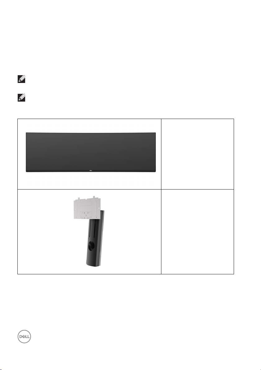
Your monitor ships with the components shown below. Ensure that you have
received all the components and Contact Dell if something is missing.
NOTE: Some items may be optional and may not ship with your monitor.
Some features or media may not be available in certain countries.
NOTE: To set up with any other stand, please refer to the respective
stand setup guide for setup instructions.
Monitor
Stand Riser
6 │ About Your Monitor
Page 7
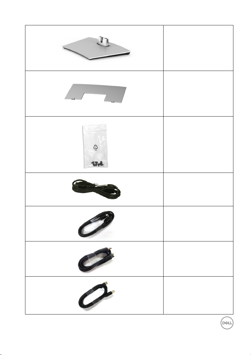
Stand Base
VESA Cover
Screws x 4 for VESA
mount
Power Cable (Varies by
Country)
HDMI Cable
DP Cable (DP to DP)
USB 3.0 Upstream Cable
(Enables the USB Ports
on the Monitor)
About Your Monitor │ 7
Page 8
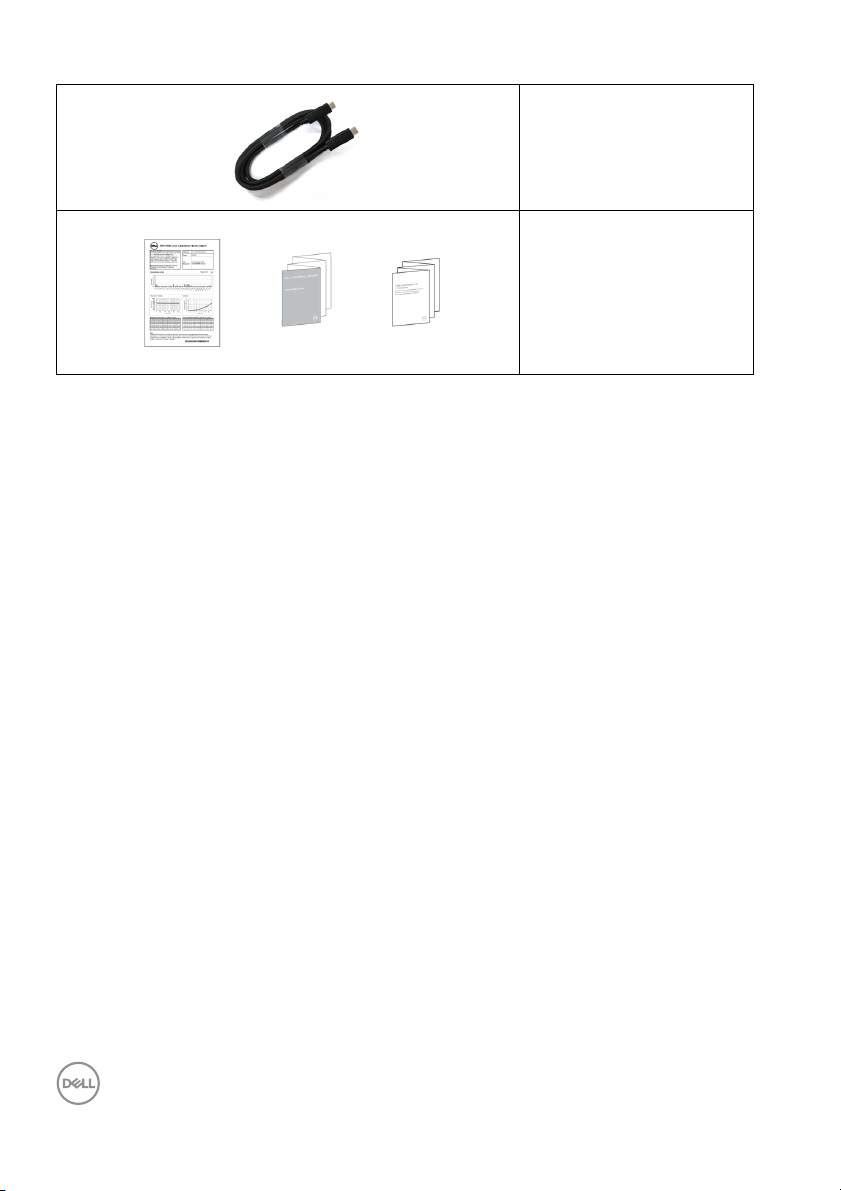
USB Type-C Cable
•Quick Setup Guide
•Factory Calibration
Re
port
• Safety, Environmental,
egulatory
and R
Information
8 │ About Your Monitor
Page 9

Product Features
The Dell U4919DW flat panel display has an active matrix, Thin-Film Transistor
(TFT), Liquid Crystal Display (LCD) and LED backlight. The monitor features
include:
• 124.46 cm (49-inch) viewable area display (measured diagonal ly).
5120 x 1440 (32:9) resolution, plus full-screen support for lower resolutions.
• Wide viewing angle to allow viewing from a sitting or standing position.
• Color gamut of 99% sRGB with an average Delta E < 2.
• Supports HDMI, USB Type-C, DP sources.
• HDMI/DP connection supports 10-bit color at 60 Hz. USB Type-C connection
supports 8-bit color at 60 Hz.
• Single USB Type-C to supply power (Up to 90 W) to a compatible notebook
while receiving video & data signal.
• Til t, swivel, and vertical extension adjustment capabilities.
• Ultra-thin bezel minimizes the bezel gap in multi-monitor usage, enabling
easier setup with an elegant viewing experience.
• Removable stand and Video Electronics Standards Association (VESA™)
100 mm mounting holes for flexible mounting solutions.
• Plug and play capability if supported by your system.
• On-Screen Display (OSD) adjustments for ease of set-up and screen
optimization.
• Power and Menu buttons lock.
• Security lock slot.
• 0.5 W standby power when in the sleep mode.
• Supports Picture by Picture (PBP) Select mode.
• Allow user to switch USB KVM function in PBP mode.
• Optimize eye comfort with a flicker-free screen.
NOTE: The possible long-term effects of blue light emission from the
monitor may cause damage to the eyes, including eye fatigue or digital
eye strain. ComfortView feature is designed to reduce the amount of
blue light emitted from the monitor to optimize eye comfort.
About Your Monitor │ 9
Page 10
Identifying Parts and Controls
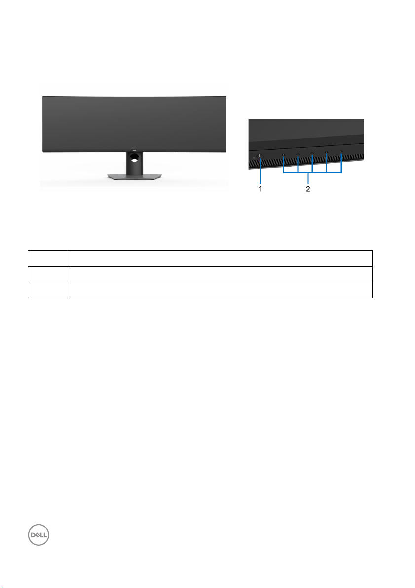
Front View
Front panel controls
Label
1 Power On/Off button (with LED indicator)
2 Function buttons (For more information, see Operating the Monitor)
Description
10 │ About Your Monitor
Page 11
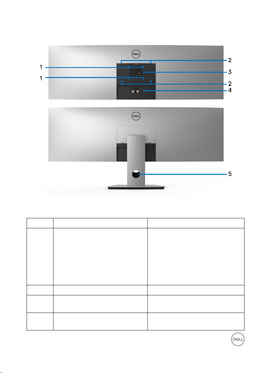
Back View
Back view without and with monitor stand
Label
1, 2 VESA mounting holes of 100 mm
x 1
00 mm (1) and 200 mm x 100
mm (2) are supported.
3 Regulatory label Lists the regulatory approvals.
4 Barcode serial number label Refer to this label if you need to
5 Cable management slot Use to organize cables by placing
Description Use
Attach stand to the monitor using
200 mm x 100 mm with M4 x 10
mm screws.
For third party wall mount, it is
ecommended using 200 mm x 100
r
mm VESA-compatible wal l mount
kit with M4 x 10 mm screws.
c
ontact Dell for technical support.
them
through the slot.
About Your Monitor │ 11
Page 12
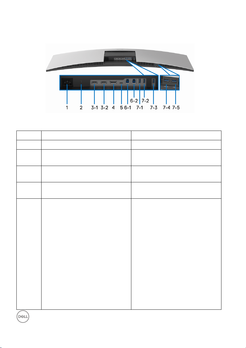
Bottom View
Bottom view without monitor stand
Label Description Use
1 AC power connector Connect the power cable.
2 Security lock slot Secures monitor with security lock
(
security lock not included).
3
HDMI port connector Connect your computer with
(1, 2
)
4 DisplayPort in connector Connect your computer with DP
5 USB Type-C port Connect the USB Type-C cable
HDMI cable.
cab
le.
tha
t came with your monitor to the
computer or mobile device. This
port supports USB Power Delivery,
Data, and DisplayPort video signal.
The USB Type-C port offers the
astest transfer rate and the
f
al ternate mode with DP1.4
supports a maximum resolution of
5120 x 1440 at 60 Hz,
PD 20 V/4.5 A, 20 V/3.25 A, 15 V/
A, 9 V/3 A, and 5 V/3 A.
3
NOTE: US
supported on versions of Windows
prior to Windows 10.
B Type-C is not
12 │ About Your Monitor
Page 13
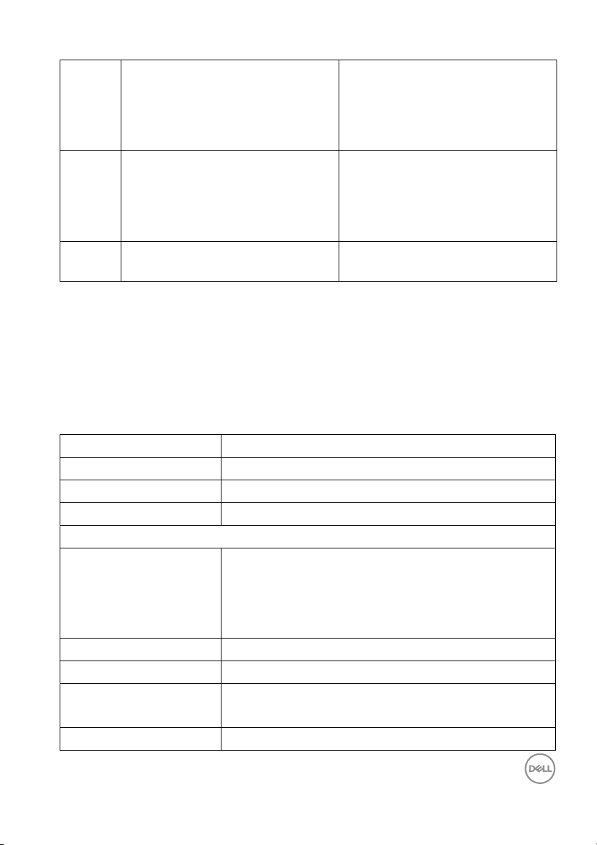
6
USB upstream port Connect the USB cable that came
(1, 2)
7
USB downstream port Connect your USB device. You can
(1, 2, 3,
5)
7-4 USB downstream port with Power
Charging
* To avoid signal interference, when a wireless USB device has been connected to
a USB downstream port, it is NOT recommended to connect any other USB
devices to the adjacent port(s).
with your monitor to the computer.
Once this cable is connected, you
can use the USB connectors on
the monitor.
onl y use this connector after you
have connected the USB cable to
the computer and USB upstream
connector on the monitor.*
Connect to charge your device.
Monitor Specifications
Flat Panel Specifications
Model U4919DW
Screen type Active matrix - TFT LCD
Panel technology In-Plane Switching Type
Aspect ratio 32:9
Viewable image
Diagonal
Horizontal, Active Area
Vertica l, Active Area
Area
Pixel pitch 0.234 mm x 0.234 mm
Pixel per inch 109
Viewing angle 178° (vertical) typical
Luminance output 350 cd/m² (typical)
1244.6 mm (49 inches)
1198.08 mm (47.17 inches)
336.96 mm (13.27 inches)
403705 mm2 (625.74 inch2)
178° (horizontal) typical
About Your Monitor │ 13
Page 14

Contrast ratio 1000 to 1 (typical)
Faceplate coating Antiglare with hard-coating 3H
Backlight White LED edgelight system
Response time 8 ms for NORMAL mode
5 ms for FAST mode
Color depth 1.07 billion colors
Color gamut* 99% sRGB
Calibration accuracy Del ta E < 2 (average)
Built-in devices •2 x USB 3.0 upstream port
•5 x USB 3.0 downstream ports
•1 x USB Type-C port
Connectivity • 2 x HDMI 2.0 (HDCP 2.2) (10-bit color @ 60 Hz)
• 1 x DP 1.4 (HDCP 2.2) (10-bit color @ 60 Hz)
•5 x USB 3.0 Downstream port
•2 x USB 3.0 Upstream port
• 1 x USB Type-C (Alternate mode with DP1.4, Power
Delivery, and USB2.0) (8-bit color @ 60 Hz)
Border width (edge of
monitor to active area)
12.2 mm (Top)
11.0 mm (Left/Right)
17.4 mm (Bottom)
Adjustability
Height adjustable stand
Ti l t
Swivel
Pivot
NOTE: Do not mount or use this monitor in portrait (vertical) orientation or inverse
(180°) landscape mount as it may damage the monitor.
Del l Display Manager
0 to 90 mm
-5° to 21°
-170° to 170°
N/A
Easy Arrange, Input Manager, Auto Source, etc.
(DDM) Compatibility
Security Security lock slot (cable lock sold separately)
* Color gamut (typical) is based on CIE1976 (90%) and CIE1931 (75%) test
standards.
14 │ About Your Monitor
Page 15
Resolution Specifications
Model U4919DW
Horizontal scan range
(HDMI & DP & USB Type-C al ternate mode)
Vertica l sc an range
(HDMI & DP & USB Type-C al ternate mode)
Maximum preset resolution 5120 x 1440 at 60 Hz
Supported Video Modes
Model U4919DW
Video display capabilities (HDMI playback) 480p, 576p, 720p, 1080i, 1080p,
Preset Display Modes
25 kHz to 115 kHz (automatic)
24 Hz to 86 Hz (automatic)
(In
terlacing mode is not
supported under PBP mode)
Display Mode Horizontal
equency
Fr
(kHz)
VESA, 720 x 400 31.5 70.0 28.3 -/+
VESA, 640 x 480 31.5 60.0 25.2 -/-
VESA, 640 x 480 37.5 75.0 31.5 -/-
VESA, 800 x 600 37.9 60.0 40.0 +/+
VESA, 800 x 600 46.9 75.0 49.5 +/+
VESA, 1024 x 768 48.4 60.0 65.0 -/-
VESA, 1024 x 768 60.0 75.0 78.8 +/+
VESA, 1280 x 1024 64.0 60.0 108.0 +/+
VESA, 1280 x 1024 80.0 75.0 135.0 +/+
VESA, 1152 x 864 67.5 75.0 108.0 +/+
Vertical
Frequency
(Hz)
Pixel
Clock
(MHz)
About Your Monitor │ 15
Sync Polarity
(Horizontal/
Vertical)
Page 16
VESA, 1600 x 900 60.0 60.0 108.0 +/+
VESA, 1920 x 1080 67.5 60.0 148.5 +/+
VESA, 2560 x 1440 88.8 60.0 234.4 +/+
VESA, 3840 x 1080 66.6 60.0 261.0 +/-
VESA, 5120 x 1440
#
88.8 60.0 461.6 +/+
# Requires a graphics card that supports HDMI 2.0.
# Requires a graphics card that supports DP1.2 or above.
* Recommend user to disable YPbPr color format.
Electrical Specifications
Model U4919DW
Video input signals HDMI 2.0*/DP 1.4, 600 mV for each differential line,
1
00 ohm input impedance per differential pair.
AC input vo l tage/
fr
equency/current
100 VAC to 240 VAC / 50 Hz or 60 Hz + 3 Hz / 3 A
(typical)
Inrush current • 120 V: 40 A (Max.) at 25 °C
• 240 V: 80 A (Max.) at 25 °C
* Not Support HDMI 2.0 optional specification,
include HDMI Ethernet Channel
(HEC), Audio Return Channel (ARC), standard for 3D format and resolutions, and
standard for 4K digital cinema resolution.
16 │ About Your Monitor
Page 17
Physical Characteristics
Model U4919DW
Connec
Signal cable type
Dimensions (with stand)
Height (extended) 548.6 mm (21.60 inches)
Height (compressed) 458.6 mm (18.06 inches)
Width 1215.1 mm (47.84 inches)
Depth 252.6 mm (9.94 inches)
Dimensions (without stand)
Height 371 mm (14.61 inches)
Width 1215.1 mm (47.84 inches)
Depth 109.3 mm (4.30 inches)
Stand dimensions
Height (extended) 433.5 mm (17.07 inches)
Height (compressed) 343.5 mm (13.52 inches)
Width 380.3 mm (14.97 inches)
Depth 252.6 mm (9.94 inches)
tor Type
• DP1.4, black connector
•HDMI2.0
•USB 3.0
•USB Type-C
• Digital: Detachable, HDMI, 19 pins
• Digital: DisplayPort, 20 pins
• Digital: Type-C Port, 24 pins
• Universal Serial Bus: USB, 9 pins
About Your Monitor │ 17
Page 18
Physical Characteristics (Continued)
Weight
Weight with packaging 26.43 kg (58.27 lb)
Weight with stand assembl y and
cab
les
Weight without stand assembly
(For wall mount or VESA mount
consid
erations - no cables)
Weight of stand assembl y 5.34 kg (11.77 lb)
Front frame gloss Black Frame - 30 gloss unit (max.)
Environmental Characteristics
Model U4919DW
Comp
liant Standards
• ENERGY STAR certified monitor
• EPEAT registered where applicable. EPEAT registration varies by country. See
www.epeat.net for registration status by country.
•RoHS-compliant
• TCO certified displays
• BFR/PVC-free (Halogen-free) excluding external cables
• Arsenic-free glass and Mercury-free for the panel only
Te m p er at u r e
Operating 0 °C to 40 °C (32 °F to 104 °F)
Non-operating -20 °C to 60 °C (-4 °F to 140 °F)
Humidity
Operating 20% to 80% (non-condensing)
Non-operating 10% to 90% (non-condensing)
Altitude
Operating 3,048 m (10,000 ft) (maximum)
Non-operating 12,192 m (40,000 ft) (maximum)
Thermal dissipation
• 784.3 BTU/hour (maximum)
•204.6 BTU/hour (typical)
17.20 kg (37.92 lb)
11.40 kg (25.13 lb)
18 │ About Your Monitor
Page 19
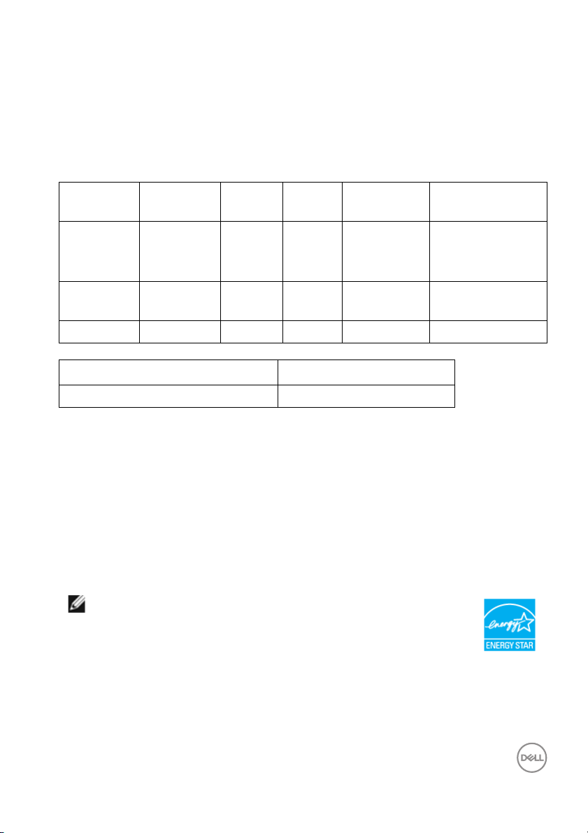
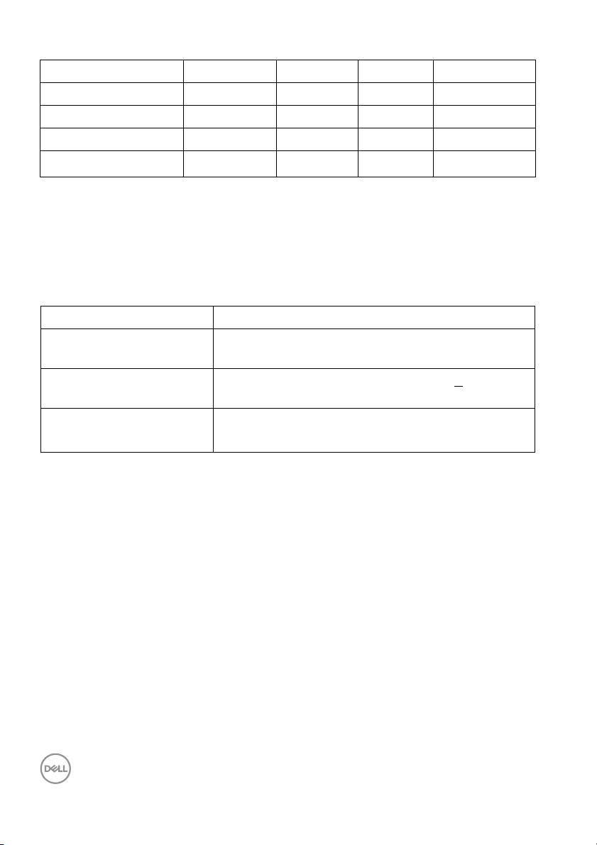
Power Management Modes
If you have VESA's DPM™ compliance display c
ard or software installed in your PC,
the monitor can automatically reduce its power consumption when not in use. This
is referred to as Power Save Mode*. If the computer detects input from the
keyboard, mouse, or other input devices, the monitor automatically resumes
functioning. The following table shows the power consumption and signaling of this
automatic power saving feature.
VESA
des
Mo
Normal
oper
ation
Horizontal
Sync
Active Active Active White 230 W
Vertical
Sync
Video Power
Indicator
Power
Consumption
(maximum)**
60 W (typical)
Active-off
mod
e
Inactive Inactive Blanked White
(blinking)
Less than 0.5 W
Switch off - - - Off Less than 0.3 W
Power Consumption P
on
35.25 W
Total Energy Consumption (TEC) 111.66 kWh
* Zero power consumption in OFF mode can only be achie
ved by disconnecting the
main cable from the monitor.
** Maximum power consumption with
This document is informational only and
max luminance, and USB active.
reflects laboratory performance. Your
product may perform differently, depending on the software, components and
peripherals you ordered and shall have no obligation to update such information.
Accordingly, the customer should not rely upon this information in making decisions
about electrical tolerances or otherwise. No warranty as to accuracy or
completeness is expressed or implied.
NOTE:
This monitor is ENERGY STAR certified.
This product qualifies for ENERGY STAR in the factory
default
settings which can be restored by “Factory
Reset” function in the OSD menu. Changing the factory
default settings or enabling other features may increase
power consumption that could exceed the ENERGY
STAR specified limit.
About Your Monitor │ 19
Page 20
NOTE:
: Power consumption of On Mode as defined in ENERGY STAR 8.0
P
on
version.
TEC: Total energy consumption in kWh as defined in ENERGY STAR
0 version.
8.
The OSD functions only in the normal operation mode. When any button is pressed
in the Active-off mode, the following message will be displayed:
Activate the computer and the monitor to gain access to the OSD.
NOTE: The message may be slightly different according to the
connected input signal.
20 │ About Your Monitor
Page 21
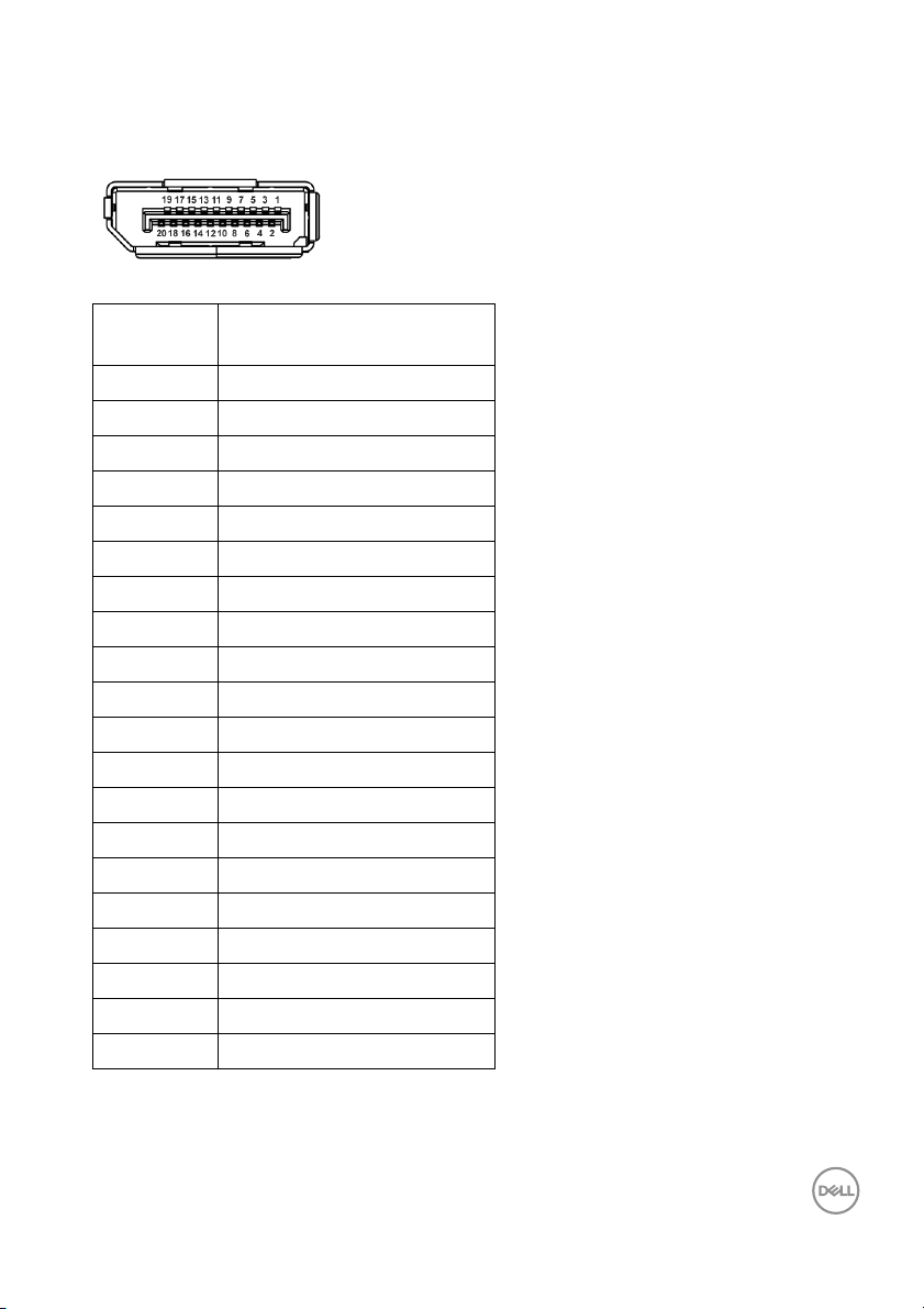
Pin Assignments
DisplayPort Connector
Pin
Number
1 ML3 (n)
2 GND
3 ML3 (p)
4 ML2 (n)
5 GND
6 ML2 (p)
7 ML1 (n)
8 GND
9 ML1 (p)
10 ML0 (n)
11 GND
12 ML0 (p)
13 GND
14 GND
15 AUX (p)
16 GND
17 AUX (n)
18 Hot Plug Detect
19 Re-PWR
20 +3.3 V DP_PWR
20-pin Side of the
Connected Signal Cable
About Your Monitor │ 21
Page 22
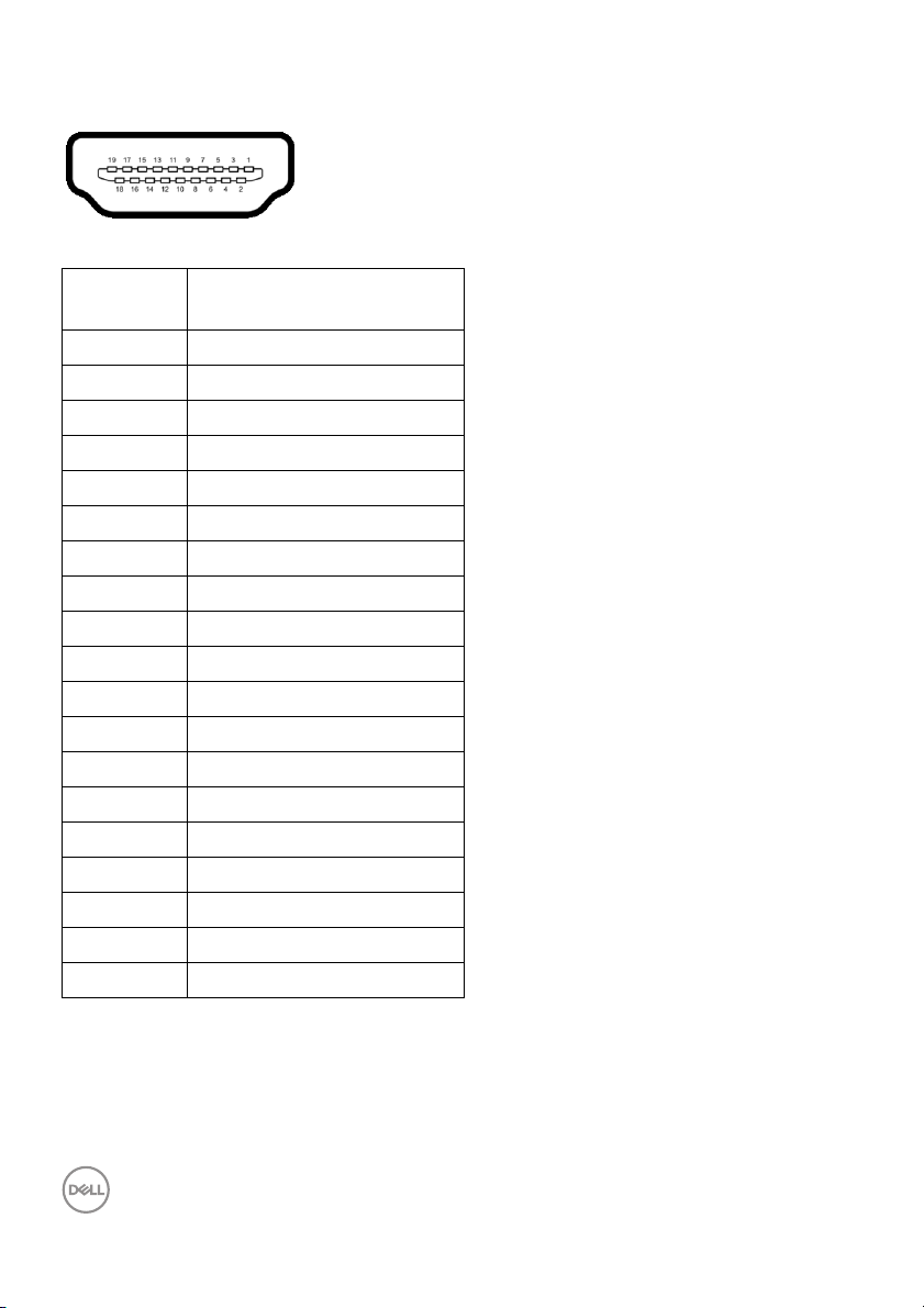
HDMI Connector
Pin
Number
1 TMDS DATA 2+
2 TMDS DATA 2 SHIELD
3 TMDS DATA 2-
4 TMDS DATA 1+
5 TMDS DATA 1 SHIELD
6 TMDS DATA 1-
7 TMDS DATA 0+
8 TMDS DATA 0 SHIELD
9 TMDS DATA 0-
10 TMDS CLOCK+
11 TMDS CLOCK SHIELD
12 TMDS CLOCK-
13 CEC
14 Reserved (N.C. on device)
15 DDC CLOCK (SCL)
16 DDC DATA (SDA)
17 DDC/CEC Ground
18 +5V POWER
19 HOT PLUG DETECT
19-pin Side of the
Connected Signal Cable
22 │ About Your Monitor
Page 23
Plug and Play Capability
You can install the monitor in any Plug and Play-compatible system. The monitor
automatically provides the computer system with its Extended Display Identification
Data (EDID) using Display Data Channel (DDC) protocols so the system can
configure itself and optimize the monitor settings. Most monitor installations are
automatic; you can select different settings if desired. For more information about
changing the monitor settings, see Operating the Monitor.
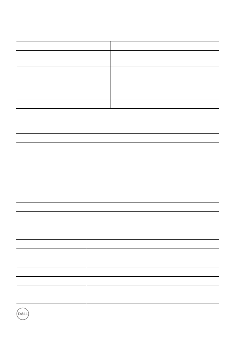
Universal Serial Bus (USB) Interface
This section gives you information about the USB ports that are available on the
monitor.
NOTE: This monitor is Super-Speed USB 3.0 compatible.
Transfer Speed Data Rate Power Consumption*
Super-speed 5 Gbps 4.5 W (Max, each port)
High speed 480 Mbps 4.5 W (Max, each port)
Full speed 12 Mbps 4.5 W (Max, each port)
* Up to 2A on USB downst
compliance devices or normal USB devices.
USB Type-C Description
Video DP 1.2/DP 1.4
Data USB 2.0
Power Delivery (PD) Up to 90 W (typical)
NOTE: USB Type-C video requires a Type-C Alternate Mode capability
computer.
NOTE: To support USB Type-C Alternate Mode DP 1.4, please ensure
the Source computer has Alternate Mode DP 1.4 capability.
NOTE: For USB Type-C to DP Adapter information, go to http://
www.dell.com and search P/N: H21XJ.
ream port (port with battery icon) with BC1.2
About Your Monitor │ 23
Page 24
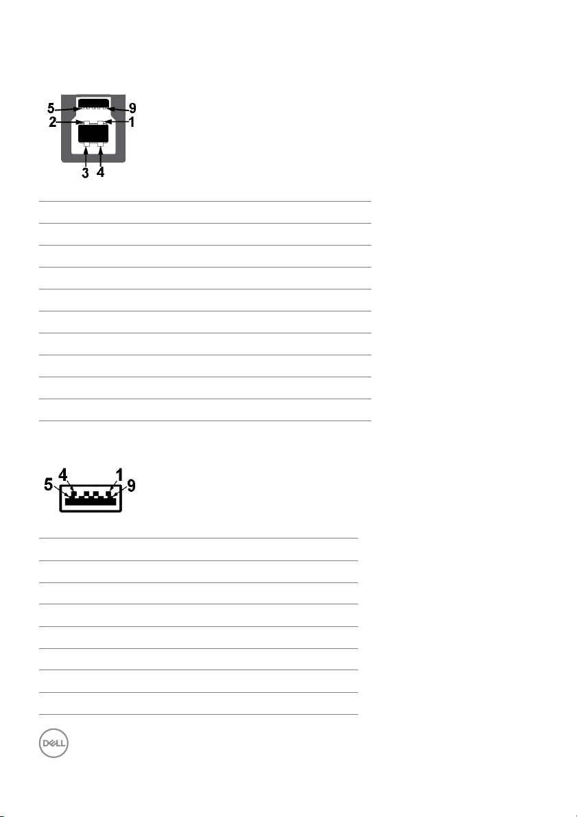
USB Upstream Connector
Pin Number 9-pin Side of the Connector
1 VCC
2 D-
3 D+
4 GND
5 SSTX-
6 SSTX+
7 GND
8 SSRX-
9 SSRX+
USB Downstream Connector
Pin Number 9-pin Side of the Connector
1 VCC
2 D-
3 D+
4 GND
5 SSRX-
6 SSRX+
7 GND
24 │ About Your Monitor
Page 25

8 SS
9 SSTX+
USB Type-C Connector
Pin Number Signal Name Pin Number Signal Name
A1 GND B1 GND
A2 TX1+ B2 TX2+
A3 TX1- B3 TX2-
A4 VBUS B4 VBUS
A5 CC B5 VCONN
A6 D+ B6
A7 D- B7
A8 SBU1 B8 SBU2
A9 VBUS B9 VBUS
A10 RX2- B10 RX1-
A11 RX2+ B11 RX1+
A12 GND B12 GND
TX-
USB Ports
• 1 x USB Type-C - bottom
•2 x USB 3.0 upstream - bottom
• 5 x USB 3.0 downstream - bottom
About Your Monitor │ 25
Page 26

• Power Charging Port- the port with battery icon; supports fast current
charging capability if the device is BC1.2 compatible.
NOTE: USB 3.0 functionality requires a USB 3.0-capable computer.
NOTE: The monitor's USB interface works only when the monitor is On
or in the power save mode. If you turn Off the monitor and then turn it
On, the attached peripherals may take a few seconds to resume normal
functionality.
LCD Monitor Quality and Pixel Policy
During the LCD Monitor manufacturing process, it is not uncommon for one or more
pixels to become fixed in an unchanging state which are hard to see and do not
affect the display quality or usability. For more information on Dell Monitor Quality
and Pixel Policy, see Dell Support site at:
monitors.
http://www.dell.com/support/
Maintenance Guidelines
Cleaning Your Monitor
CAUTION: Read and follow the Safety Instructions before cleaning the
monitor.
WARNING: Before cleaning the monitor, unplug the monitor power
cable from the electrical outlet.
For best practices, follow the instructions in the list below while unpacking, cleaning,
or handling your monitor:
• To clean your anti-static screen, lightly dampen a soft, clean cloth with water.
If possible, use a special screen-cleaning tissue or solution suitable for the
anti-static coating. Do not use benzene, thinner, ammonia, abrasive cleaners,
or compressed air.
• Use a lightl y-dampened, warm cloth to clean the monitor. Avoid using
detergent of any kind as some detergents leave a milky fil m on the monitor.
• If you notice white powder when you unpack your monitor, wipe it off with a
cloth.
• Handle your monitor with care as a darker-colored monitor may get scratched
and show white scuff marks more than a lighter-colored monitor.
• To help maintain the best image quality on your monitor, use a dynamically
changing screen saver and turn Off your monitor when not in use.
26 │ About Your Monitor
Page 27

Setting Up the Monitor
Attaching the Stand
NOTE: The stand is detached when the monitor is shipped from the
factory.
NOTE: This is applicable for a monitor with a stand. When any other
stand is bought, please refer to the respective stand setup guide for
the set up instructions.
CAUTION: Do
attaching the stand.
To attach the monitor stand:
ol low the instructions on the flaps of carton to remove the stand from the
1. F
top cushion that secures it.
rt the stand base blocks fully into the stand slot.
2. Inse
3. L
ift the screw handle and turn the screw clockwise.
4. A
fter fully tightening the screw, fold the screw handle flat within the recess.
not remove the monitor from the packaging box before
Setting Up the Monitor │ 27
Page 28

5. Lift the cover, as shown, to expose the VESA area for stand assembly.
6. Attach the stand assembly to the monitor.
a. Fit the two tabs on the upper part of the stand to the groove on the back of
the monitor.
b. Use a Phillips crosshead screwdriver to attach the four screws to secure
the stand assembl y to the monitor.
NOTE: When attaching the stand assembly, tilt the stand base upwards
and make sure that the stand base does not hit the surface.
28 │ Setting Up the Monitor
Page 29

7. Attach the VESA cover to the monitor.
a. Insert the cover with the lower part downward. Do NOT attach the latch at
this point.
b. Til t to fit the three tabs on the upper part of the cover to the groove of the
back of the monitor.
c. Press the cover down till the latch snaps into place.
Setting Up the Monitor │ 29
Page 30

8. Hold the monitor holders firmly, and lift the monitor carefully to prevent it
from slipping or falling.
NOTE: The monitor is very heavy; handle with extreme care. It is
recommended to have two people to lift or move this monitor.
30 │ Setting Up the Monitor
Page 31

9. Set the monitor in place, and remove the monitor holders from the monitor.
NOTE: The monitor is very heavy; handle with extreme care. It is
recommended to have two people to lift or move this monitor.
CAUTION: Do
not press on the panel screen when lifting the monitor.
Setting Up the Monitor │ 31
Page 32

Wall Mounting/3rd Party Arm (Optional)
NOTE: Wall Mount Kit/3rd Party Arm Kit is NOT included in this
monitor.
CAUTION: Do no
attaching the mounting bracket from the Wall Mount Kit/3rd Party Arm
Kit.
Refer to the instructions that come wit
bracket.
ttach the mounting bracket onto the monitor.
1. A
t remove the monitor from the packaging box before
h the VESA-compatible wall mounting
32 │ Setting Up the Monitor
Page 33

2. Hold the monitor holders firmly, and lift the monitor carefull y to prevent it
from slipping or falling. Attach the monitor to the Wall Mount/3rd Party Arm
following its respective instructions.
NOTE: The monitor is very heavy; handle with extreme care. It is
recommended to have two people to lift or move this monitor.
fter attaching the monitor to the Wall Mount/3rd Party Arm, remove the
3. A
monitor holder from the monitor.
Setting Up the Monitor │ 33
Page 34

4. When using as dual monitor stacked on top of each other, set up must compl y
to the recommended panel orientation and working angle, as shown.
NOTE: In double stacked scenario using 3rd Party Arm, the top monitor
should not be rotated 180° (landscape). The monitor should not be
orientated at 90° (portrait).
34 │ Setting Up the Monitor
Page 35

Connecting Your Monitor
WARNING: Before you begin any of the procedures in this section,
fol low the Safety Instructions.
NOTE: Do not connect all cables to the computer at the same time.
To connect your monitor to the computer:
1. T
urn Off your computer and disconnect the power cable.
2. Conne
Connecting the HDMI cable
NOTE: The default out of factory setting in the U4919DW is HDMI 2.0.
If the monitor fails to show any content after the HDMI cable is
connected, follow the procedures below to change the settings from
HDMI 2.0 to HDMI 1.4:
ct the HDMI/DP/USB Type-C cable from the monitor to your computer
or USB Type-C device.
• Press second button next to the button to activate the OSD menu.
• Use the and buttons to highlight Input Source, then use the
button enter the submenu.
• Use the and buttons to highlight HDMI.
• Press and hold the button for approximately 10 seconds, and the
HDMI configuration message appears.
Setting Up the Monitor │ 35
Page 36

• Use the button to select Disable and change the settings.
Repeat the above steps to change the HDMI format settings if necessary.
Connecting the DisplayPort (DP to DP) cable
NOTE: The default out of factory setting in the U4919DW is DP1.4.
36 │ Setting Up the Monitor
Page 37

Connecting the USB Type-C cable
NOTE: Use the USB Type-C cable shipped with monitor only.
• This port supports DisplayPort Alternate Mode DP 1.4.
•
The USB Type-C power delivery compliant port (PD Version 2.0) delivers
up to 90 W of power.
• If your notebook requires more than 90 W to operate and the battery is
drained, it may not be powered up or charged with the USB PD port of
U4919DW.
CAUTION: The graphics are used for the purpose of illustration only.
Appearance of the computer may vary.
Setting Up the Monitor │ 37
Page 38

Connecting the USB 3.0 cable
NOTE: To prevent data damage or loss, before changing USB upstream
ports, make sure that NO USB storage devices are in use by the
computer connected to the monitor’s USB upstream port.
After you have completed connecting the HDMI/DP/USB Type-C cable, follow the
ures below to connect the USB 3.0 cable to the computer and complete
proced
your monitor setup:
1. a. Connect one computer: co
supplied) to an appropriate USB 3.0 port on your computer.
b. Connect two computers*: connec
appropriate USB 3.0 ports on the two computers. Then use the OSD menu to
select between the two USB upstream sources and input sources. See USB
Select Switch.
2. Connec
monitor.
3. Pl
t the USB 3.0 peripherals to the downstream USB 3.0 ports on the
ug the power cables for your computer(s) and monitor into a nearby outlet.
nnect the upstream USB 3.0 port (cable
t the upstream USB 3.0 ports to
a. Connect one computer
b. Connect two computers
38 │ Setting Up the Monitor
Page 39

* When connecting two computers to the monitor, the monitor's USB downstream
ports for the keyboard and mouse can be assigned to different input signals from
the two computers by changing the USB Selection settings from the OSD menu.
(See USB Selection for details).
urn On the monitor and the computer(s).
4. T
If your monitor disp lays an image, installation is complete. If it does not display
an image
5. Use
, see Universal Serial Bus (USB) Specific Problems.
the cable slot on the monitor stand to organize the cables.
Organizing Your Cables
After attaching all necessary cables to your monitor and computer, (See
Connecting Your Monitor for cable attachment,) organize all cables as shown
above.
Setting Up the Monitor │ 39
Page 40

Removing the Monitor Stand
NOTE: To prevent the curved LCD screen from being scratched and
damaged while removing the stand, ensure that the monitor is placed
on a soft, clean foam. Direct contact with hard objects might cause
damage to the curved monitor.
NOTE: The monitor is very heavy; handle with extreme care. It is
recommended to have two people to lift or move this monitor.
NOTE: This is applicable for a monitor with a stand. When any other
stand is bought, please refer to the respective stand setup guide for
the set-up instructions.
To remove the stand:
ace the monitor on a soft cloth or cushion.
1. Pl
2. Pr
ess and lift the cover latch to release and remove the cover.
40 │ Setting Up the Monitor
Page 41

3. Use a Phil lips crosshead screwdriver to remove the four screws securing the
stand.
4. Lift the stand up and away from the monitor.
Setting Up the Monitor │ 41
Page 42

Operating the Monitor
Power On the Monitor
Press the button to turn On the monitor.
Using the Front Panel Controls
Use the control buttons on the front of the monitor to adjust settings.
The following table describes the front panel buttons:
Front Panel Button Description
1
Power
(with power light
indicator)
42 │ Operating the Monitor
Use the Po
and Off.
The white light indicates the monitor is On and
fu
the power save mode.
lly functional. A glowing white light indicates
wer button to turn the monitor On
Page 43

2
Shortcut key/
Preset Modes
3
Shortcut key/
Brightness/Contrast
4
Shortcut key/
Input Source
5
Menu
6
Exit
Front Panel Button
Use the buttons on the front of the monitor to
Use this button to choose from a list of preset
lor modes.
co
Use this button to adjust the brightness and
trast. Minimum is ‘0’ (-). Maximum is ‘100’ (+).
con
Use this button to select the input source.
Use the MENU b
Display (OSD). See Accessing the Menu
System.
Use this button to exit the OSD main menu.
utton to launch the On-Screen
adjust the image settings.
Front Panel Button Description
1
No Function This button has no function.
2
Up
Use the Up button to adjust (increase ranges) items in the
OSD menu.
Operating the Monitor │ 43
Page 44

3
Do
wn
4
Enter
5
Exit
Use the Down button to adjust (decrease ranges) items in
the OSD menu.
Use the Enter button to enter a submenu.
Use this button to exit the OSD main menu.
Using the On-Screen Display (OSD) Menu
Accessing the Menu System
NOTE: If you change the settings and then either proceed to another
menu or exit the OSD menu, the monitor automatically saves those
changes. The changes are also saved if you change the settings and
then wait for the OSD menu to disappear.
ess the button to launch the OSD menu and display the main menu.
1. Pr
2. Press the and buttons to move between the setting options. As you
move from one icon to another, the option name is highlighted. See the
f
ollowing table for a complete list of all the options available for the monitor.
ess the button once to activate the highlighted option.
3. Pr
44 │ Operating the Monitor
Page 45

4. Press and button to select the desired parameter.
5. Press to enter the submenu and then use the directional buttons,
according to the indicators on the menu, to make your changes.
6. Se
lect the button to return to the main menu.
Icon Menu and
Submenus
Brightness/
Contrast
Brightness Brightness adjusts the luminance of the backlight.
Description
Use this menu to activate Brightness/Contrast
adjustment.
Press the
press the
(min. 0 / max. 100).
button to increase the brightness and
button to decrease the brightness
Operating the Monitor │ 45
Page 46

Contrast Adjust the Brightness first, and then adjust the
Contrast only if further adjustment is necessary.
Press the
the
button to increase the contrast and press
button to decrease the contrast (min. 0 /
max. 100).
The Con
trast function adjusts the degree of difference
between darkness and lightness on the monitor screen.
Input Source Use the Input Source menu to select between the
different video signals that may be connected to your
monitor.
USB Type-C Select the USB Type-C input when you are using the
USB Type-C connector. Press the
the USB Type-C input source.
DP Select the DP
(DP) connector. Press the
DisplayPort input source.
HDMI 1 Select the HDM
connector. Press the
input source.
46 │ Operating the Monitor
button to select
input when you are using the DisplayPort
button to select the
I 1 input when you are using the HDMI 1
button to select the HDMI 1
Page 47

HDMI 2 Select the HDMI 2 input when you are using the HDMI
2 connector. Press the
button to select the HDMI 2
input source.
Auto Select Turning on the function allows you to scan for available
inp
ut sources.
Auto Select for
USB-C
Allows you to set Auto Select for USB-C to:
• Pr
ompt for Multiple Inputs: Always displays the
“Switch to USB-C Video Input” message for you
to choose whether to switch or not.
s: Always switch to USB-C video input (without
• Ye
asking) when the USB Type-C cable is connected.
• No: Ne
ver automatically switch to USB-C video input
when the USB Type-C cable is connected.
NOTE: Auto Select for USB-C is
only available when
Auto Select is turned On.
Reset Input
Sour
ce
Reset your monitor input settings to the factory
settings.
Color Use Color to adjust the color setting mode.
Operating the Monitor │ 47
Page 48

Preset Modes When you select Preset Modes, you can choose
Standard, ComfortView, Movie, Game, Color
Te m p. ,or Custom Color from the list.
• Standard: Loads the monitor's default color settings.
This is the default preset mode.
• ComfortView: Decreases the level of the blue light
emitted from the screen to make viewing more
comfortable for your eyes.
WARNING: The possible long-term effects of blue light
emission from the monitor may cause personal injury
such as digital eye strain, eye fatigue and damage to the
eyes. Using monitor for extended periods of time may
also cause pain in parts of body such as neck, arm, back
and shoulder.
To reduce the risk of eye strain and neck/arm/back/
shoulder pain from using the monitor for long periods of
time, we suggest you to:
1. Set the distance of the screen between 20 inches
to 28 inches (50 cm-70 cm) from your eyes.
2. Blink frequently to moisten your eyes or wet your
eyes with water after prolonged usage of the
monitor.
3. Take regular and frequent breaks for 20 minutes
every two hours.
4. Look away from your monitor and gaze at a distant
object at 20 feet away for at least 20 seconds
during the breaks.
5. Perform stretches to relieve tension in the neck,
arm, back, and shoulders during the breaks.
48 │ Operating the Monitor
Page 49

• Movie: Loads color settings ideal for movies.
• Game: L
oads color settings ideal for most gaming
applications.
lor Temp.: Allows users to select the color
• Co
temperature: 5000K, 5700K, 6500K, 7500K, 9300K,
and 10000K. Press the
button to select a
preferred color temperature.
• Cust
om Color: Allows you to manual l y adjust the
color settings. Press the
adjust the Ga
in, Offset, Hue, and Saturation
and buttons to
values and create your own preset color mode.
Operating the Monitor │ 49
Page 50

Input Color
Format
Allows you to set the video input mode to:
RGB: Se
lect this option if your monitor is connected to
a computer (or DVD player) using the DP or HDMI or
USB Type-C cable. Press the
button to select the
RGB mode.
YPbPr:
only YPbPr output. Press the
Select this option if your DVD player supports
button to select the
YPbPr mode.
Hue This feature can shift the color of the video image to
green or purple. This is used to adjust the desired flesh
tone color. Use
or to adjust the hue from '0' to
'100'.
Use
Use
NOTE: Hue ad
select Movie or Game preset mode.
50 │ Operating the Monitor
to increase the green shade of the video image.
to increase the purple shade of the video image.
justment is available onl y when you
Page 51

Saturation This feature can adjust the color saturation of the video
image. Use
'100'.
Use
image.
Use
video image.
NOTE: Saturation adjustmen
you select Movie or Game preset mode.
Reset Color Reset your monitor color settings to the factory
se
ttings.
Display Use Display to adjust images.
or to adjust the saturation from '0' to
to increase the colorful appearance of the video
to increase the monochrome appearance of the
t is available onl y when
Aspect Ratio Adjusts the image ratio to Wide 32:9, Auto Resize,
4:3, or 1:1.
Sharpness This feature can make the image look sharper or softer.
Use
or to adjust the sharpness from '0' to '100'.
Operating the Monitor │ 51
Page 52

Response Time Allows you to set the Response Time to Normal or
Fast.
Uniformity
Compensa
Reset Display Select this option to restore default display settings.
PBP This function brings up a window displaying image from
Select screen uniformity compensation settings.
tion
Calibrated is factory calibrated setting by default.
Uniformity Compensation adjusts different areas of
the screen with respect to the center to achieve uniform
brightness and color over the entire screen. For optimal
screen performance, Brightness and Contrast for
some preset modes (Standard, Color Temp.) will be
disabled when Uniformity Compensation is turned
On.
NOTE: User is
setting when Uniformity Compensation is turned on.
For other brightness level setting, the uniformity
performance may deviate from the data shown on the
Factory Calibration Report.
another input source.
advised to use factory default brightness
52 │ Operating the Monitor
Page 53

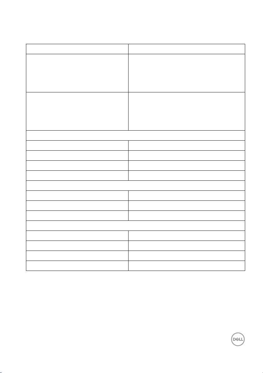
X
X
X
X
X
Main Window
Sub-Window
USB Type-C
DP
USB Type-C
DP
HDMI 1
HDMI 1
HDMI 2
HDMI 2
NOTE: The images under PBP will be displayed at the
center of the screen, not full screen.
PBP Mode Adjusts the PBP (P
PBP or Off.
X
X
X
icture by Picture) mode between
Press the
button to enable PBP mode.
Operating the Monitor │ 53
Page 54

PBP (Sub) Select between the different video signals that may be
connected to your monitor for the PBP sub-window.
USB Select
Switch
Press the
button to select the PBP sub-window
source signal.
Select to switch between the USB upstream sources in
PBP mode. Press the
button to switch among USB
upstream sources in PBP mode.
54 │ Operating the Monitor
Page 55

Video Swap Select to swap videos between main window and sub-
window in PBP mode. Press the
button to swap
main window and sub-window.
Contrast (Sub) Adjust the contrast level of the picture in PBP Mode.
Press the
the
button to increase the contrast and press
button to decrease the contrast.
Operating the Monitor │ 55
Page 56

USB Selection Allows you to set the USB upstream port for the input
signals (DP, HDMI 1, and HDMI 2), thus the monitor's
USB downstream port (eg. keyboard and mouse) can be
used by the current input signals when you connect a
computer to either one of the upstream ports.
When you use only one upstream port, the connected
eam port is active.
upstr
NOTE: To prevent data damage or loss, before
changing USB upstream ports, make sure that NO USB
storage devices are in use by the computer connected
to the monitor’s USB upstream port.
56 │ Operating the Monitor
Page 57

Menu Select this option to adjust the settings of the OSD,
such as, the languages of the OSD, the amount of time
the menu remains on screen, and so on.
Language Language options set the OSD display to one of the
eight languages (English, Spanish, French, German,
Brazilian Portuguese, Russian, Simplified Chinese or
Japanese).
Tran sp ar ency Select this option to change the menu transparency by
essing the
pr
Maximum: 100).
Ti me r OSD Hold Time: se
remain active after the last time you pressed a button.
Use
increments, from 5 to 60 seconds.
or to adjust the slider in 1 second
and buttons (Minimum: 0 ~
ts the length of time the OSD will
Operating the Monitor │ 57
Page 58

Lock With the control buttons on the monitor locked, you can
prevent people from accessing the controls. It also
prevents accidental activation in multiple monitors sideby-side setup.
• Menu Buttons: All Menu/function buttons (except
the Power button) are locked and not accessible by
the user.
wer Button: Onl y the Power button is locked and
• Po
not accessible by the user.
• Menu +
Power buttons are locked and not accessible by the
user.
The default setting is Disab
Alternative Lock Method [for Menu/function buttons]:
Y
ou can also press and hold the Menu/function button
next to the Power button for 4 seconds to set the lock
options.
NOTE: T
Menu/function button next to the Power button for 4
seconds.
Reset Menu Reset al l OSD settings to the factory preset values.
Power Buttons: Both the Menu/function &
le.
o unlock the button(s), press and hold the
58 │ Operating the Monitor
Page 59

Personal ize
Shortcut Key 1 Al lows you to choose a feature from Preset Modes,
Shortcut Key 2
Shortcut Key 3
Power Button
LED
USB-A
Char
ging
USB-C
Char
ging
Brightness/Contrast, Input Source, Aspect Ratio,
PBP Mode, USB Select Switch, or Video Swap and
set it as a shortcut key.
Allows you to set the power LED indicator On or Off to
ave energy.
s
Allows you to enable or disable USB Type-A
(Downstream Ports) charging function during monitor
standby mode.
NOTE: Th
Type-C (Upstream Port) cable is unplugged. If the USB
Type-C cable is connected, USB-A Charging follows the
USB host power status and the option is not accessible.
NOTE: T
monitor firmware revisions.
Allows you to enable or disable Always On USB
Ty p e - C C h a rg i n g func
mode.
NOTE: Th
firmware revisions.
is option is only available when the USB
his option was previously called USB in older
tion during monitor Power Off
is option is only available in newer monitor
Operating the Monitor │ 59
Page 60

Monitor Sleep Al lows you to let the monitor turn off automatical l y or
stay on when your computer goes into sleep mode.
When Enable is selected, the monitor goes to sleep as
the system sleeps; when Disable is selected, you may
prevent the screen from going off as the system sleeps
for speedy display recovery from PC wake up.
Reset
ersonalization
P
Others
Display Info Displays the monitor's current settings.
Reset all settings under the Personal ize menu to the
factory preset values
60 │ Operating the Monitor
Page 61

DDC/CI DDC/CI (Display Data Channel/Command Interface)
al lows your monitor parameters (brightness, color
balance, and etc.) to be adjustable via the software on
your computer.
You can disable this feature by selecting Of
Enable this feature for best user experience and
timum performance of your monitor.
op
f.
LCD
Conditioning
Firmware Displays the firmware version of your monitor.
Helps reduce minor cases of image retention.
Depending on the degree of image retention, the
program may take some time to run. You can enable this
feature by selecting On.
Operating the Monitor │ 61
Page 62

Service Tag Displays the service tag serial number of your monitor.
Reset Others Reset all settings under the Other
s menu to the factory
preset values.
Factory Reset Restore all preset values to the factory default settings.
These
are also the settings for ENERGY STAR
®
tests.
OSD Warning Messages
When the monitor does not support a particular resolution mode, you will see the
following message:
NOTE: The message may be slightly different according to the
connected input signal.
This means that the monitor cannot synchronize with the signal that it is receiving
rom the computer. See Monitor Specifications for the Horizontal and Vertical
f
frequency ranges addressable by this monitor.
Recommended mode is 5120 x 1440.
62 │ Operating the Monitor
Page 63

You will see the following message before the DDC/CI function is disabled:
You will see the following message before the Lock function is activated:
NOTE: The message may be slightly different according to the selected
settings.
When the monitor enters the Po
wer Save mode, the following message appears:
Activate the computer and wake up the monitor to gain access to the OSD.
NOTE: The message may be slightly different according to the
connected input signal.
Operating the Monitor │ 63
Page 64

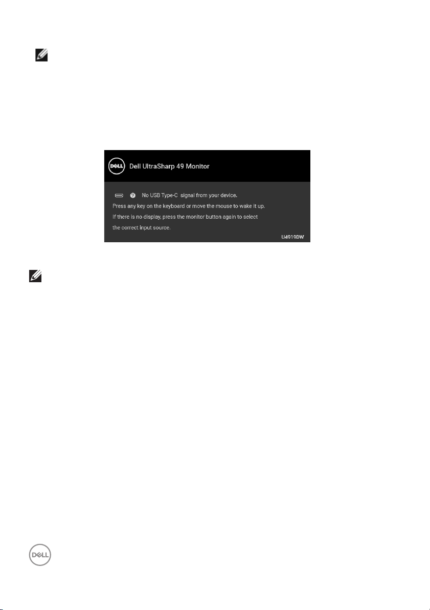
If you press any button other than the power button, the following message will
appear depending on the selected input:
NOTE: The message may be slightly different according to the
connected input signal.
If either USB Type-C, HDMI, or DP input is se
not connected, a floating dialog box as shown below appears.
lected and the corresponding cable is
NOTE: The message may be slightly different according to the
connected input signal.
64 │ Operating the Monitor
Page 65

When the monitor is under DP/HDMI input and a USB Type-C cable is connected to
a notebook that supports DP Alternate Mode, if Auto Select for USB-C is
enabled, the following
When Factory Reset is selected, the following message appears:
When Yes is selected, the following message appears:
message appears:
See Tro ub l e sh o ot i ng for more information.
Operating the Monitor │ 65
Page 66

Setting the Maximum Resolution
To set the maximum resolution for the monitor:
In Windows® 7, Windows® 8, and Windows® 8.1:
1. For Windows® 8 and Windows® 8.1 only, select the Desktop tile to switch to
classic desktop.
2. Right-click on the desktop and click Screen Resolution.
3. Click the Dropdown list of the Screen Resolution and select 5120 x 1440.
4. Click OK.
In Windows® 10:
1. Right-click on the desktop and click Display settings.
2. Click Advanced display settings.
3. Click the dropdown list of Resolution and select 5120 x 1440.
4. Click Apply.
If you do not see 5120 x 1440 as an option, you may need to check whether your
graphic card supports 4K@60 Hz. If it does support 4K@60 Hz, update your
graphic driver. If it does not support 4K@60 Hz, depending on your computer,
complete one of the following procedures:
If you have a Dell desktop or portable computer:
•Go to http://www.dell.com/support, enter your service tag, and download
the latest driver for your graphics card.
If you are using a non-Dell computer (portable or desktop):
• Go to the support site for your computer and download the latest graphic
drivers.
• Go to your graphics card website and download the latest graphic drivers.
66 │ Operating the Monitor
Page 67

Setting the KVM USB Switch
To set the KVM USB Switch as Shortcut Key for the monitor:
ess the button to launch the OSD menu and display the main menu.
1. Pr
2. Pr
ess the and buttons to “Personalize”.
3. Press the button to activate the highlighted option.
ess the button to Shortcut Key 1 to activate the highlighted option.
4. Pr
5. Pr
ess the and buttons to “USB Select Switch”.
Operating the Monitor │ 67
Page 68

6. Press the button to confirm selection.
7. Press the button to return to the main menu.
NOTE: KVM USB Switch function only work under PBP Mode.
The following are illustrations of several conne
Selection menu settings, as illustrated in corresponding color frames.
en connecting HDMI 1 + USB 1 to computer 1 and DP + USB Type-C to
1. Wh
computer 2:
NOTE: The USB Type-C connection currently supports only data
transfer.
Make sure USB Selection for HDMI 1 is set to USB 1 and DP is set to
USB Type-C.
ction scenarios and their USB
68 │ Operating the Monitor
Page 69

2. When connecting HDMI 1 + USB 1 to computer 1 and HDMI 2 + USB 2 to
computer 2:
Make sure USB Selection for HDMI 1 is set to USB 1 and HDMI 2 is set to
USB 2.
Operating the Monitor │ 69
Page 70

3. When connecting HDMI 1 + USB 1 to computer 1 and USB Type-C to
computer 2:
NOTE: The USB Type-C connection currently supports video and data
transfer.
Make sure USB Se
lection for HDMI 1 is set to USB 1.
NOTE: As the USB Type-C port suppo
Mode, there is no need to set USB Selection for USB Type-C.
NOTE: When connecting to different video input sources not shown
above, follow the same method to make correct settings for USB
Selection to pair the ports.
70 │ Operating the Monitor
rts the DisplayPort Alternate
Page 71

Using the Til t, Swivel, and Vertical Extension
NOTE: This is applicable for a monitor with a stand. When any other
stand is bought, please refer to the respective stand setup guide for set
up instructions.
Ti l t, S w ive l
With the stand attached to the monitor, you
most comfortable viewing angle.
can tilt and swivel the monitor for the
NOTE: The stand is detached when the monitor is shipped from the
factory.
Operating the Monitor │ 71
Page 72

Vertical Extension
NOTE: The stand extends vertically up to 90 mm. The figure below
illustrates how to extend the stand vertically.
Dual-Monitor Setup
The recommended dual-monitor setup:
Landscape (Top-bottom)
Due to cable length restrictions (1 m) for USB Type-C Gen2 cable, it is
recommended to connect your monitors:
• Connect the upper monitor with HDMI/DP cable.
• Connect the lower monitor with HDMI/DP/USB Type-C Gen2 cable.
72 │ Operating the Monitor
Page 73

Troubleshooting
WARNING: Before you begin any of the procedures in this section,
fol low the Safety Instructions.
Sel f-Test
Your monitor provides a self-test feature that allows you to check whether your
monitor is functioning properly. If your monitor and computer are properly
connected but the monitor screen remains dark, run the monitor self-test by
performing the following steps:
urn off both your computer and the monitor.
1. T
2. Unp
lug the video cable from the back of the computer.
3. T
urn on the monitor.
The floating dialog box should appear on-screen (against a black background), if the
mon
itor cannot sense a video signal and is working correctly. While in self-test
mode, the power LED remains white. Also, depending upon the selected input, the
dialog shown below will continuously scroll through the screen.
NOTE: The message may be slightly different according to the
connected input signal.
his box also appears during normal system operation, if the video cable
4. T
becomes disconnected or damaged.
urn Off your monitor and reconnect the video cable; then turn On both your
5. T
computer and the monitor.
If your monitor screen remains blank after y
your video controller and computer, because your monitor is functioning properly.
ou use the previous procedure, check
Tro ub l es hoot in g │ 73
Page 74

Built-in Diagnostics
Your monitor has a built-in diagnostic tool that helps you determine if the screen
abnormality you are experiencing is an inherent problem with your monitor, or with
your computer and video card.
NOTE: You can run the built-in diagnostics only when the video cable is
unplugged and the monitor is in self-test mode.
To run the built-in diagnostics:
1. Ensur
2. Unp
3. Pr
4. Car
5. Pr
6. Inspec
7. R
The test is complete when the text screen appears. To exit, press But
If you do not detect any screen abnormalities up
the monitor is functioning properly. Check the video card and computer.
e that the screen is clean (no dust particles on the surface of the
screen).
lug the video cable(s) from the back of the computer or monitor. The
monitor then goes into the self-test mode.
ess and hold Button 2 on the front panel for 5 seconds. A gray screen
appears.
efully inspect the screen for abnormalities.
ess Button 2 on the front panel again. The color of the screen changes to
red.
t the display for any abnormalities.
epeat steps 5 and 6 to inspect the display in green, blue, black, white and
text screens.
ton 2 again.
on using the built-in diagnostic tool,
74 │ Tro ub l esh oo ti ng
Page 75

Always On USB Type-C Charging
The monitor allows you to charge your notebook or mobile devices through the USB
Type-C cable even when the monitor is powered off. See
more information. This feature is only available when the monitor firmware revision
is M2B102 or later.
You may verify your current firmware revision in Firmware. If this is not available,
go to the Dell download support site for the latest application installer (Monitor
Firmware Update Utility.exe) and refer to the Firmware Update Instruction
User’s Guide:
www.dell.com/U4919DW
USB-C Charging for
Common Problems
The following table contains general information about common monitor problems
you might encounter and the possible solutions:
Common
Symptoms
No Video/
Power LED off
No Video/
Power LED on
What You
Experience
No picture • Ensure that the video cable connecting the
monitor and the computer is properly
connected and secure.
• Verify that the power outlet is functioning
properly using any other electrical equipment.
• Ensure that the power button is pressed fully.
• Ensure that the correct input source is
selected in the
No picture or
no
brightness
• Increase brightness & contrast controls via
OSD.
• Perform monitor self-test feature check.
• Check for bent or broken pins in the video
cable connector.
• Run the built-in diagnostics.
• Ensure that the correct input source is
selected in the
Possible Solutions
Input Source menu.
Input Source menu.
Tro ub l es hoot in g │ 75
Page 76

Poor Focus Picture is
fuzzy, blurry,
or ghosting
Shaky/Jittery
Video
Missing Pixels LCD screen
Stuck-on Pixels LCD screen
Brightness
Problems
Geometric
Distortion
Wavy picture
or fine
movement
has spots
has bright
spots
Picture too
dim or too
bright
Screen not
centered
correctly
• Eliminate video extension cables.
• Reset the monitor to factory settings.
• Change the video resolution to the correct
aspect ratio.
• Reset the monitor to factory settings.
• Check environmental factors.
• Relocate the monitor and test in another
room.
•Cycle power On-Off.
• Pixel that is permanently Off is a natural
defect that can occur in LCD technology.
• For more information on Dell Monitor Quality
and Pixel Policy, see Dell Support site at:
http://www.dell.com/support/monitors.
•Cycle power On-Off.
• Pixel that is permanently off is a natural
defect that can occur in LCD technology.
• For more information on Dell Monitor Quality
and Pixel Policy, see Dell Support site at:
http://www.dell.com/support/monitors.
• Reset the monitor to factory settings.
• Adjust brightness & contrast controls via
OSD.
• Reset the monitor to factory settings.
• Adjust horizontal & vertical controls via OSD.
76 │ Tro ub l e sh o ot in g
Page 77

Horizontal/
Vertica l Lines
Synchronization
Problems
Safety Related
Issues
Intermittent
Problems
Missing Color Picture
Screen has
one or more
lines
Screen is
scrambled or
appears torn
Visible signs
of smoke or
sparks
Monitor
mal functions
on & off
missing color
• Reset the monitor to factory settings.
• Perform monitor self-test feature check and
determine if these lines are also in self-test
mode.
• Check for bent or broken pins in the video
cable connector.
• Run the built-in diagnostics.
• Reset the monitor to factory settings.
• Perform monitor self-test feature check to
determine if the scrambled screen appears in
sel f-test mode.
• Check for bent or broken pins in the video
cable connector.
• Restart the computer in the safe mode.
• Do not perform any troubleshooting steps.
•Contact Dell immediately.
• Ensure that the video cable connecting the
monitor to the computer is connected
properly and is secure.
• Reset the monitor to factory settings.
• Perform monitor self-test feature check to
determine if the intermittent problem occurs
in sel f-test mode.
• Perform monitor self-test feature check.
• Ensure that the video cable connecting the
monitor to the computer is connected
properly and is secure.
• Check for bent or broken pins in the video
cable connector.
Tro ub l e sh o ot in g │ 77
Page 78

Wrong Color Picture color
not good
Image retention
from a static
image left on
the monitor for
a long period of
time
Image Ghosting Fast moving
Faint
shadow from
the static
image
displayed
appears on
the screen
images leave
a trail of
shadow
images
• Change the settings of the Preset Modes in
the Color menu OSD depending on the
application.
• Adjust R/G/B value under Custom Color in
Color menu OSD.
•Change the Input Color Format to PC RGB
or YPbPr in the Color menu OSD.
• Run the built-in diagnostics.
• Use the Power Management feature to turn
off the monitor at all times when not in use
(for more information, see
Management Modes).
• Alternatively, use a dynamical ly changing
screensaver.
• Change the Response Time in the Display
menu.
Power
78 │ Tro ub l e sh o ot in g
Page 79

Product Specific Problems
Specific
Symptoms
Screen image
is
too small
Cannot adjust
the monit
with the
buttons on the
front panel
No Input Signal
wh
controls are
pressed
The picture
do
the entire
screen
or
en user
es not fill
What You
Experience
Image is
centered on
screen, but
does not fill
entire viewing
area
OSD does not
appear on
screen
No picture,
the LED
is white
The picture
canno
height or
width of the
screen
the
light
t fill the
Possible Solutions
• Check the Asp
Display menu OSD.
• Reset the monitor to factory settings.
• Turn Off the monitor, unplug the power cord,
plug it back, and then turn On the monitor.
• Check whether the OSD menu is locked. If
es, press and hold the Menu/function button
y
next to the Power button for 4 seconds to
unlock (for more information, see Lock).
• Check the signal source. Ensure the computer
is not in the power saving mode by moving
the mouse or pressing any key on the
keyboard.
• Check whether the signal cable is plugged in
operly. Re-plug the signal cable if
pr
necessary.
• Reset the computer or video player.
• Due to different video formats (aspect ratio)
f DVDs, the monitor may display in ful l
o
screen.
• Run the built-in diagnostics.
ect Ratio setting in the
Tro ub l e sh o ot in g │ 79
Page 80

No Video, No
Display
Display image
at 5
120 x 1440
@ 30 Hz at
HDMI port
Monitor
splayed
di
image at 3840
x 1080 @ 60
Hz
No video
when
connecting
docking,
dongle or
Blu-ray DVD
players
Not able to
lect 5120 x
se
1440 @ 60
Hz in Graphic
Control Panel
at HDMI Port
Not able to
lect 5120 x
se
1440 in
Graphic
Control Panel
• Due to legacy platform cannot recognize or
output
EDID to lower resolution to cover this
compatibility problem:
1. R
2. Cho
• Due to legacy platform HDMI 1.4 HW
ban
x 1440 @ 30 Hz.
• Due to legacy platform HW limitation, it does
no
• To support 5120 x 1440 @ 60 Hz, check
wh
fol lowing:
1. DP
2. T
3. HDMI 2.
5120 x 1440, we suggest to change
emove all input cables, press Buttons 3
and 4 for 5 seconds. (Please refer to
page 74 for button numbers)
ose “Enable” on POP up screen to
change max reso lution from 5120 x 1440 to
3840 x 1080.
dwidth limitation, it can onl y support 5120
t support 5120 x 1440.
ether the platform meet either one of the
1.2 or higher.
ype-C Alt Mode DP1.2 or higher.
0.
80 │ Tro ub l es hooti ng
Page 81

Universal Serial Bus (USB) Specific Problems
Specific
Symptoms
USB interface
is not working
USB Type-C
port does not
suppl y power
What You
Experience
USB
peripherals
are not
working
USB
peripherals
can not be
charged
Possible Solutions
• Check that your monitor is turned On.
• Ensure USB Selection is set correctly in the
USB Selection menu.
• Reconnect the upstream cable to your
computer.
• Reconnect the USB peripherals (downstream
connector).
• Switch Off and then turn On the monitor
again.
• Reboot the computer.
• Some USB devices like external portable HDD
require higher electric current; connect the
device directly to the computer system.
• Disconnect one upstream USB cable when
using two upstream connections.
• Check that the connected device is compliant
with the USB-C specification. The USB TypeC port supports USB 2.0 and an output of
90 W.
• Check that you use the USB Type-C cable
shipped with your monitor.
Tro ub l es hoot in g │ 81
Page 82

High Speed
USB 3.0
interface is
slow
Wireless
mouse is not
working or
lagging
High Speed
USB 3.0
peripherals
working
slowly or not
working at al l
Do not
respond or
responds
slowly
• Check that your computer is USB 3.0capable.
• Some computers have USB 3.0, USB 2.0, and
USB 1.1 ports. Ensure that the correct USB
port is used.
• Reconnect the upstream cable to your
computer.
• Reconnect the USB peripherals (downstream
connector).
• Reboot the computer.
• Increase the distance between the USB 3.0
peripherals and the wireless USB receiver.
• Position your wireless USB receiver as close
as possible to the wireless mouse.
• Use a USB-extender cable to position the
wireless USB receiver as far away as possible
from the USB 3.0 port.
82 │ Tro ub l e sh o ot i ng
Page 83

Appendix
WARNING: Safety Instructions
WARNING: Use of controls, adjustments, or procedures other than
those specified in this documentation may result in exposure to shock,
electrical hazards, and/or mechanical hazards.
For information on safety instructions, see the Safety, Environmental, and
Regulatory Information (SERI).
FCC Notices (U.S. Only) and Other Regulatory Information
For FCC notices and other regulatory information, see the regulatory compliance
website located at
Contact Del l
For customers in the United States, call 800-WWW-DELL (800-999-3355).
NOTE: If you do not have an active Internet connection, you can find
contact information on your purchase invoice, packing slip, bill, or Dell
product catalog.
Dell provides several online and telephone-based support and service
options. Availability varies by country and product, and some services may
not be available in your area.
• Online technical assistance ─ www.dell.com/support/monitors
•Contacting Dell ─ www.dell.com/contactdell
www.dell.com/regulatory_compliance.
Appendix │ 83
 Loading...