

Page 1

Dell EMC PowerEdge R540 System
Technical Guide
Mar ch 202 1
Rev . A 04
Page 2

Notes, cautions, and warnings
NOTE: A NOTE indicates important information that helps you make better use of your product.
CAUTION: A CAUTION indicates either potential damage to hardware or loss of data and tells you how to avoid
the problem.
WARNING: A WARNING indicates a potential for property damage, personal injury, or death.
© 2017 - 2021 Dell Inc. or its subsidiaries. All rights reserved . D ell , E MC, and other trademarks are trademarks of Dell Inc. or its subsidi ari es.
Other trademarks may be trademarks of their respective owners.
Page 3

Contents
Figures..........................................................................................................................................5
Tables........................................................................................................................................... 6
Chapter 1: System Overview.......................................................................................................... 7
Introduction...........................................................................................................................................................................7
New technologies................................................................................................................................................................ 7
Chapter 2: System features.......................................................................................................... 9
Product comparison............................................................................................................................................................9
Technical specifications................................................................................................................................................... 10
Chapter 3: Chassis overview........................................................................................................ 12
Front view of the system.................................................................................................................................................12
Left control panel view............................................................................................................................................... 13
Right control panel view............................................................................................................................................. 16
Back panel features........................................................................................................................................................... 17
Inside the system............................................................................................................................................................... 19
Security features................................................................................................................................................................ 21
Chapter 4: Processors.................................................................................................................23
Supported processors...................................................................................................................................................... 23
Chipset.................................................................................................................................................................................25
Chapter 5: System memory......................................................................................................... 26
General memory module installation guidelines.......................................................................................................... 27
Chapter 6: Storage......................................................................................................................29
IDSDM with vFlash card.................................................................................................................................................. 29
Optical Drives..................................................................................................................................................................... 30
Tape Drives......................................................................................................................................................................... 30
Boot Optimized Storage Subsystem............................................................................................................................ 30
Chapter 7: Networking and PCIe..................................................................................................32
LAN on Motherboard(LOM)........................................................................................................................................... 32
PCIe Expansion cards....................................................................................................................................................... 32
Chapter 8: Trusted platform module ........................................................................................... 34
Chapter 9: Video specifications................................................................................................... 35
Chapter 10: Power, Thermal, and Acoustics.................................................................................36
Power consumption and energy efficiency................................................................................................................. 36
Power supply units............................................................................................................................................................37
Contents 3
Page 4

Thermal and Acoustics.....................................................................................................................................................37
Thermal design............................................................................................................................................................. 37
Acoustical design......................................................................................................................................................... 38
Chapter 11: Rack rails.................................................................................................................. 39
Chapter 12: Dell EMC OpenManage systems management........................................................... 49
iDRAC with Lifecycle controller.....................................................................................................................................50
Server and Chassis Managers........................................................................................................................................ 56
Dell EMC consoles............................................................................................................................................................ 56
Automation Enablers........................................................................................................................................................ 56
Integration with third-party consoles........................................................................................................................... 57
Connections for third-party consoles...........................................................................................................................57
Dell EMC Update Utilities................................................................................................................................................ 57
Dell resources..................................................................................................................................................................... 57
Chapter 13: Appendix A. Additional specifications....................................................................... 58
PSU specifications............................................................................................................................................................ 58
System dimensions........................................................................................................................................................... 59
Chassis weight................................................................................................................................................................... 59
Environmental specifications..........................................................................................................................................59
Chapter 14: Appendix B. Standards compliance........................................................................... 60
Chapter 15: Appendix C Additional resources............................................................................... 61
Chapter 16: Appendix D. Support and deployment services..........................................................62
Dell EMC ProDeploy Enterprise Suite ......................................................................................................................... 62
Dell EMC ProDeploy Plus...........................................................................................................................................62
Dell EMC ProDeploy....................................................................................................................................................63
Dell EMC Basic Deployment......................................................................................................................................63
Dell EMC Residency Services................................................................................................................................... 63
Deployment services........................................................................................................................................................ 63
Dell EMC Remote Consulting Services........................................................................................................................ 63
Dell EMC Data Migration Service..................................................................................................................................63
ProSupport Enterprise Suite.......................................................................................................................................... 63
ProSupport Plus.................................................................................................................................................................64
ProSupport..........................................................................................................................................................................64
ProSupport One for Data Center.................................................................................................................................. 64
Support Technologies...................................................................................................................................................... 65
Additional professional services.....................................................................................................................................66
Dell Education Services................................................................................................................................................... 66
Dell EMC Global Infrastructure Consulting Services................................................................................................ 66
Dell EMC Managed Services.......................................................................................................................................... 66
4
Contents
Page 5

Figures
1 Dell EMC PowerEdge R540..................................................................................................................................... 7
2 Front view of 12 x 3.5 inch drive system............................................................................................................ 12
3 Front view of 8 x 3.5 inch drive system............................................................................................................. 12
4 Left control panel without optional iDRAC Quick Sync 2.0 indicator.......................................................... 13
5 Left control panel with optional iDRAC Quick Sync 2.0 indicator................................................................ 14
6 iDRAC Quick Sync 2 indicators............................................................................................................................. 15
7 Right control panel................................................................................................................................................... 16
8 Back panel features of 12 x 3.5 inch + 2 x 3.5 inch (rear) drive system.................................................... 17
9 Back panel features of 12 x 3.5 inch + 2 x 3.5 inch (rear) drive system.................................................... 17
10 Back panel features of 12 x 3.5 inch drive system with butterfly riser....................................................... 18
11 Inside the system without rear drive cage........................................................................................................ 20
12 Inside the system with rear drive cage............................................................................................................... 21
13 Boot Optimized Storage Subsystem (BOSS).................................................................................................... 31
14 Configuration A: LOM riser + 3 x low profile slot + riser blank.................................................................... 32
15 Configuration B: LOM riser + Right riser + 2 x 3.5 inch rear hard drive.................................................... 32
16 Configuration C: LOM riser + Left riser + Right riser + 2 x 3.5 inch rear hard drive.............................. 33
17 Configuration D: LOM riser + Butterfly riser + 3 x low profile slot............................................................. 33
18 Sliding rails with optional CMA............................................................................................................................. 39
19 Static rails..................................................................................................................................................................40
20 Static rails in 2-post center mount configuration.............................................................................................41
21 Sliding rails with CMA............................................................................................................................................. 42
22 Pull out inner rail...................................................................................................................................................... 44
23 Rail standoffs seated in J-slots............................................................................................................................ 44
24 Slide system into the rack..................................................................................................................................... 45
25 Pull out the intermediate rail................................................................................................................................. 46
26 Attach the inner rails to the system....................................................................................................................47
27 Install system into the extended rails..................................................................................................................48
28 Slide system into the rack..................................................................................................................................... 48
29 Dell EMC OpenManage Portfolio......................................................................................................................... 49
30 Dimensions of the PowerEdge R540 system....................................................................................................59
31 ProDeploy Enterprise Suite capabilities..............................................................................................................62
32 ProSupport Enterprise Suite................................................................................................................................. 64
33 ProSupport One for Data Center model............................................................................................................ 65
34 SupportAssist model............................................................................................................................................... 65
Figures 5
Page 6

Tables
1 New technologies.......................................................................................................................................................7
2 Feature comparison...................................................................................................................................................9
3 Technical specifications.......................................................................................................................................... 10
4 R540 chassis options............................................................................................................................................... 12
5 Features available on the front of the system.................................................................................................. 13
6 Left control panel..................................................................................................................................................... 14
7 Status LED indicators and descriptions.............................................................................................................. 14
8 iDRAC Quick Sync 2 indicators and descriptions............................................................................................. 15
9 Right control panel...................................................................................................................................................16
10 iDRAC Direct LED indicator codes....................................................................................................................... 17
11 Back panel features of R540................................................................................................................................. 18
12 Security features...................................................................................................................................................... 21
13 Supported Processors for R540.......................................................................................................................... 23
14 Supported Memory................................................................................................................................................. 26
15 DIMM Performance Details................................................................................................................................... 26
16 Supported RAS features........................................................................................................................................ 27
17 PERC series controller offerings..........................................................................................................................29
18 BOSS RAID controller features............................................................................................................................. 31
19 Supported video resolution options.................................................................................................................... 35
20 Power tools and technologies...............................................................................................................................36
21 Acoustical reference points and output comparisons.....................................................................................38
22 Static, Sliding, or Stab-in/Drop-in sliding rails.................................................................................................. 41
23 Rail Adjustability Range and Rail Depth..............................................................................................................42
24 Rail component.........................................................................................................................................................46
25 iDRAC feature comparison....................................................................................................................................50
26 Dell resources........................................................................................................................................................... 57
27 PSU specifications...................................................................................................................................................58
28 Dimensions of the PowerEdge R540 system....................................................................................................59
29 Chassis weight......................................................................................................................................................... 59
30 Industry standard documents............................................................................................................................... 60
31 Additional resources.................................................................................................................................................61
6 Tables
Page 7
System Overview
R540 Overview
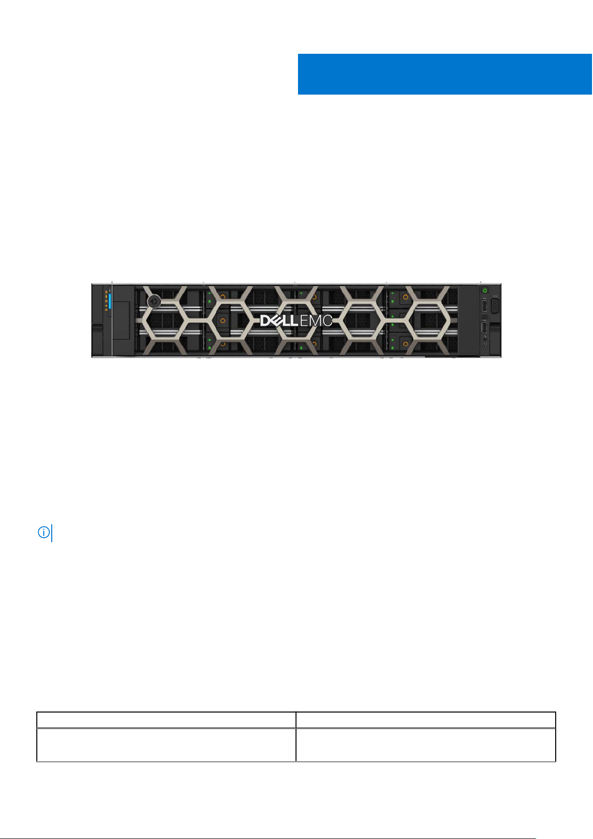
Power your applications with a versatile 2-socket, 2U general-purpose rack server. Support various applications such as
virtualization, video streaming, web tech, data analytics, and mail and messaging with the flexible Dell EMC PowerEdge R540.
Its balanced combination of resources, expandability, and affordability adapt to the changing demands of a modern data center.
Optimize your application performance with one-button tuning. Scale for future requirements with up to 14 x 3.5" drives.
Embedded diagnostics and SupportAssist help to maximize uptime without added effort, in a worry-free environment.
1
Figure 1. Dell EMC PowerEdge R540
Topics:
• Introduction
• New technologies
Introduction
The PowerEdge R540 is a general-purpose platform with highly expandable memory - up to 512 GB with single processor and up
to 1 TB with dual processors, and impressive I/O capabilities to match.
NOTE: 768 GB max memory is recommended for performance optimized configurations.
The R540 features:
● The 2nd Generation Intel® Xeon® Scalable processors product family (with up to 20 cores and two threads per core)
● Up to six channels with two DIMMs per channel per CPU and 16 DIMMs (supports DDR4 RDIMM)
● PCI Express (PCIe) 3.0 enabled expansion slots (with up to 48 lanes per CPU)
● M.2 based Boot Optimized Storage Solution module
● Modular storage and PCIe riser options
New technologies
The following are the new technologies that are featured on the PowerEdge R540:
Table 1. New technologies
New technology Detailed description
The 2nd Generation Intel® Xeon® Scalable processor The 2nd Generation Intel® Xeon® Processor product family
has advanced features such as, embedded PCIe lanes
System Overview 7
Page 8

Table 1. New technologies (continued)
New technology Detailed description
for improved I/O performance that delivers exceptional
performance and value.
For details, see the Processor section.
Intel C620 series chipset The R540 system uses the Intel C620 chipset. It is a 2 chip
platform - CPU and PCH.
2666 MT/s DDR4 memory The Intel® Xeon® Scalable processor product family supports
2666 MT/s memory and sixteen 288-pin DIMMs.
The R540 system supports:
● 6x DDR4 Channels per socket, 2 DIMMs per channel
● Up to 2666 MT/s (configuration-dependent)
● RDIMMs up to 32 GB, LRDIMMs 64 GB
For details, see the Memory section.
iDRAC9 with Lifecycle Controller The new embedded systems management solution for the
Dell EMC systems features hardware and firmware inventory
and alerting, data center level power monitoring, and faster
performance.
For details, see the Dell EMC OpenManage systems
management section
PERC S140 This new software RAID solution supports:
● RAID 0, 1, 5, and Non-RAID
● SATA hard drive and SSD devices only
● Up to eight 3.5 inch and 2.5 inch hot-plug SATA HDDs or
SSDs
● Software RAID is through the Intel Lewisburg chipset
● Software RAID solution is supported on Linux and
Windows
For details, see the Storage section.
LCD bezel The PowerEdge R540 LCD control panel is embedded in an
optional front bezel for easy access and management.
Wireless Management The Quick Sync 2 BLE/WiFi module offers secure, wireless
access to the embedded iDRAC, SupportAssist Collections,
remote RACADM, and VNC remote console connectivity.
8 System Overview
Page 9

2
System features
Compared to previous generations, the PowerEdge R540 offers faster processing power and advanced system management.
The PowerEdge R540 also provides extraordinary storage capacity options, making it well-suited for data-intensive applications
that require greater storage, while not sacrificing the I/O performance.
Topics:
• Product comparison
• Technical specifications
Product comparison
Table 2. Feature comparison
Feature PowerEdge R540 PowerEdge R530
Processors The 2nd Generation Intel® Xeon®
Scalable processor family
Chipset Intel C620 series chipset Intel C610
Memory 16x DDR4 RDIMM/LRDIMM 12 x DDR4 RDIMM/LRDIMM
Drive bays
PCIe Slots
RAID Controller PERC 9/10 Mini-PERC 9
Backplane
Embedded NIC
Power Supplies
12 x 3.5 inch SAS/SATA
Rear: 2 x 3.5 inch SAS/SATA
Up to 5 x PCIe Gen3
● 14 x 3.5 inches or 2.5 inch SATA/SAS
● 8 x 3.5 inch SATA/SAS
● 2 x 2.5 inches rear SATA/SAS
2x 1 Gb LOM and optional LAN on riser
card:
● 2X 1 GbE
● 2X 10 GbE
● 2X 10 GbE SFP+
● 450 W AC Cable PSU
● 495 W AC
● 750 W AC
● 750 W Mixed Mode HVDC (For China
Only)
● 750 W Mixed Mode (DC input for
China Use Only)
● 1100 W AC
● 1100 W Mixed Mode HVDC
Intel® Xeon® Processor E5-2600 v3 or
E5-2600 v4 product family
12 x 3.5 inch SAS/SATA
Up to 3 x PCIe Gen3, and 2 x PCIe Gen2
● 8 x 2.5 inches or 3.5 inches SAS/
SATA
4 x 1 Gb
● 450 W AC Cable PSU
● 495 W AC
● 750 W AC
● 1100 W AC
● 750 W DC
Remote Management iDRAC9 iDRAC8
TPM TPM 2.0 China, TPM1.2, TPM2.0 TPM China, TPM1.2, TPM2.0
Rear USB 3.0 port Two rear ports One rear port
iDRAC Direct front port Micro-AB USB Micro-AB USB
System features 9
Page 10

Table 2. Feature comparison (continued)
Feature PowerEdge R540 PowerEdge R530
Cooling Fan Up to 6 fan support Up to 6 fan support
IDSDM Module Internal Dual SD Module (IDSDM) and
vFlash
BOSS Module M.2 SATA interface None
PERC PCIe PERC 9 or PERC 10 Mini-PERC 9
Internal Dual SD Module (IDSDM)
Technical specifications
Table 3. Technical specifications
Feature PowerEdge R540 technical specification
Form factor
Processor The 2nd Generation Intel® Xeon® Processor Scalable Family
Processor sockets
Internal interconnect
Chipset Intel C620 series Chipset
Memory
2U rack
2 sockets
Up to 3 Intel Ultra Path Interconnect (Intel® UPI); up to 11.2 GT/s
● Supports DDR4 RDIMM
● Up to 512 GB RDIMM and 1 TB LRDIMMs
● 16 DIMM slots: 8 GB, 16 GB, 32 GB, DDR4 up to 2666 MT/s
I/O slots
RAID controller
Hard drives 12 x 3.5 inch + 2 x 2.5-inch rear drive bays (supports 2.5-inch drive using 3.5-inch
Embedded network adapter
Power supply
Supported operating systems
Systems management
Up to 5 x PCIeGen 3 slots plus a dedicated PERC and LOM slot
Internal - PERC S140, PERC H330, PERC H330, PERC H730P, PERC H740P
External HBA - PERC H840P and 12 Gb/s SAS HBA(non-RAID)
adapter)
LOM1: 2x1G
LOM Riser: 2x1GbE, 2X10GbE, 2x10GbE SFP+
Two hot‐plug PSUs or option for single cabled PSU
● 495 W, 750 W, 1100 W hot‐plug PSU
● Bronze efficiency 450 W cabled AC PSU
● Canonical® Ubuntu® LTS
● Citrix® XenServer®
● Microsoft Windows Server® with Hyper-V
● Red Hat® Enterprise Linux
● SUSE® Linux Enterprise Server
● VMware® ESXi
For more information, go to www.dell.com/ossupport
Dell EMC Systems management consoles and tools:
● OpenManage Enterprise
● OpenManage Mobile
● OpenManage Power Manager
Embedded Management:
10 System features
Page 11

Table 3. Technical specifications (continued)
Feature PowerEdge R540 technical specification
● iDRAC9
● iDRAC9 Direct
● iDRAC REST API with Redfish
● Quick Sync 2 BLE/wireless module
Dell EMC OpenManage Integrations :
● Microsoft® System Center
● VMware® vCenter™
● BMC Truesight
● Red Hat® Ansible® Modules
Dell EMC OpenManage Connections:
● Micro Focus Operations Manager I
● Nagios Core and Nagios XI
● IBM Tivoli® Netcool/OMNIbus
Dimensions and weight
Recommended support
● Height: 86.8 mm (3.41”)
● Width*: 434 mm (17.08”)
● Depth*: 703.76 mm (27.71”)
● Weight: 29.68 kg (65.43 lb)
NOTE: *Dimensions do not include bezel.
Dell ProSupport Plus for critical systems or Dell ProSupport for premium hardware
and software support for your PowerEdge solution. Consulting and deployment
offerings are also available.
Contact your Dell representative for more information. Availability and terms of Dell
Services vary by region. For more information, go to Dell.com/ServiceDescriptions.
System features 11
Page 12
3
Chassis overview
The PowerEdge R540 is a dual socket, 2U rack server with up to 16 DIMMs, storage capacity of up to 12 drive slots, and the 2
Generation Intel® Xeon® Scalable Family processors.
Table 4. R540 chassis options
Chassis Options Configurations
Eight drive chassis Up to eight 3.5 or 2.5 inches in 3.5-inch adapter front accessible SAS/SATA drives.
Twelve drive chassis Up to twelve 3.5 or 2.5 inches in front accessible SAS/SATA drives and two optional 3.5 inch
rear accessible SAS/SATA drives.
Topics:
• Front view of the system
• Back panel features
• Inside the system
• Security features
Front view of the system
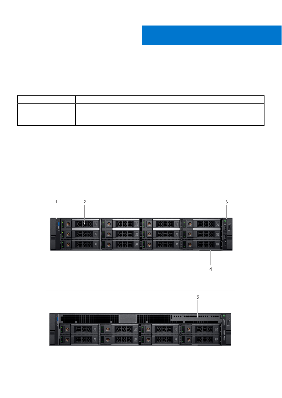
The front view displays the features available on the front of the system.
nd
Figure 2. Front view of 12 x 3.5 inch drive system
Figure 3. Front view of 8 x 3.5 inch drive system
12 Chassis overview
Page 13
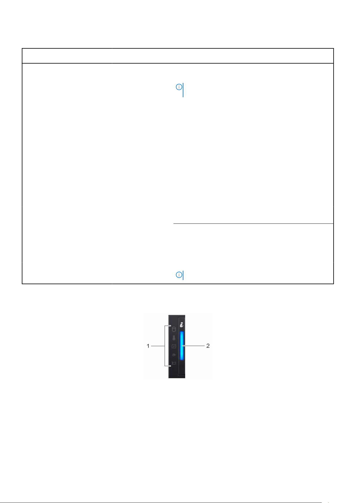
Table 5. Features available on the front of the system
Item Ports, panels, and
slots
1 Left control panel N/A
2 Drive slots N/A
3 Right control panel N/A Contains the power button, USB ports, iDRAC Direct (Micro-AB
Icon Description
Contains the system health and system ID, status LED, and the
iDRAC Quick Sync 2 (wireless) indicator.
NOTE: The iDRAC Quick Sync 2 indicator is available only
on certain configurations.
● Status LED: Enables you to identify any failed hardware
components. There are up to five status LEDs and an overall
system health LED (Chassis health and system ID) bar. For
more information, see the Status LED indicators section.
● Quick Sync 2 (wireless): Indicates a Quick Sync enabled
system. The Quick Sync feature is optional. This feature
allows management of the system by using mobile devices.
This feature aggregates hardware or firmware inventory
and various system level diagnostic and error information
that can be used in troubleshooting the system. For
more information, see the Integrated Dell Remote Access
Controller User’s Guide at Dell.com/idracmanuals.
Enable you to install drives that are supported on your
system. For more information about drives, see the Technical
specifications section.
USB), VGA port.
4 Information tag N/A
5 Optical drive (optional) N/A One optional slim SATA DVD-ROM drive or DVD+/-RW drive.
The Information tag is a slide-out label panel that contains
system information such as Service Tag, NIC, MAC address,
and so on. If you have opted for the secure default access
to iDRAC, the Information tag also contains the iDRAC secure
default password.
NOTE: DVD devices are data only.
Left control panel view
Figure 4. Left control panel without optional iDRAC Quick Sync 2.0 indicator
Chassis overview
13
Page 14
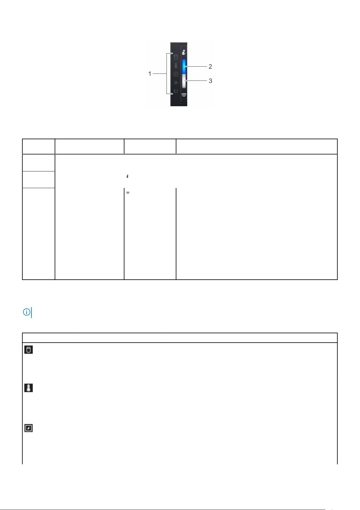
Figure 5. Left control panel with optional iDRAC Quick Sync 2.0 indicator
Table 6. Left control panel
Item Indicator, button, or
1 Status LED indicators N/A Indicate the status of the system. For more information, see the
2
3
connector
System health and system
ID indicator
iDRAC Quick Sync
2 wireless indicator
(optional)
Icon Description
Status LED indicator section.
Indicates the system health.
Indicates if the iDRAC Quick Sync 2 wireless option is activated.
The Quick Sync 2 feature allows management of the system
using mobile devices. This feature aggregates hardware/
firmware inventory and various system level diagnostic/error
information that can be used in troubleshooting the system.
You can access system inventory, Dell Lifecycle Controller
logs or system logs, system health status, and also configure
iDRAC, BIOS, and networking parameters. You can also launch
the virtual Keyboard, Video, and Mouse (KVM) viewer and
virtual Kernel-based Virtual Machine (KVM), on a supported
mobile device. For more information, see the Integrated Dell
Remote Access Controller User's Guide at www.dell.com/
poweredgemanuals
Status LED indicators
NOTE: The indicators display solid amber if any error occurs.
Table 7. Status LED indicators and descriptions
Icon Description Condition Corrective action
Drive
indicator
Temperature
indicator
Electrical
indicator
14 Chassis overview
The indicator turns solid amber if
there is a drive error.
The indicator turns solid amber
if the system experiences a
thermal error (for example, the
ambient temperature is out of
range or there is a fan failure).
The indicator turns solid amber
if the system experiences an
electrical error (for example,
voltage out of range, or a failed
power supply unit (PSU) or
voltage regulator).
● Check the System event log to determine if the drive has an error.
● Run the appropriate Online Diagnostics test. Restart the system
and run embedded diagnostics (ePSA).
● If the drives are configured in a RAID array, restart the system,
and enter the host adapter configuration utility.
Ensure that none of the following conditions exist:
● A cooling fan has been removed or has failed.
● System cover, air shroud, or back filler bracket is removed.
● Ambient temperature is too high.
● External airflow is obstructed.
Check the System event log or system messages for the specific
issue. If it is due to a problem with the PSU, check the LED on the
PSU. Reseat the PSU.
Page 15

Table 7. Status LED indicators and descriptions (continued)
Icon Description Condition Corrective action
Memory
indicator
PCIe
indicator
The indicator turns solid amber if
a memory error occurs.
The indicator turns solid amber
if a PCIe card experiences an
error.
Check the System event log or system messages for the location of
the failed memory. Reseat the memory module.
Restart the system. Update any required drivers for the PCIe card.
Reinstall the card.
iDRAC Quick Sync 2 indicator codes
iDRAC Quick Sync 2 module (optional) is located on the left control panel of your system.
Figure 6. iDRAC Quick Sync 2 indicators
Table 8. iDRAC Quick Sync 2 indicators and descriptions
iDRAC Quick Sync 2 indicator
code
Off (default state) Indicates that the iDRAC Quick Sync 2
Solid white Indicates that iDRAC Quick Sync 2 is
Blinks white rapidly Indicates data transfer activity.
Condition Corrective action
If the LED fails to turn on, reseat the left control
feature is turned off. Press the iDRAC
Quick Sync 2 button to turn on the
iDRAC Quick Sync 2 feature.
ready to communicate. Press the iDRAC
Quick Sync 2 button to turn off.
panel flex cable and check.
If the LED fails to turn off, restart the system.
NA
Blinks white slowly Indicates that firmware update is in
progress.
Blinks white five times rapidly
and then turns off
Solid amber Indicates that the system is in fail-safe
Blinking amber Indicates that the iDRAC Quick Sync 2
Indicates that the iDRAC Quick Sync 2
feature is disabled.
mode.
hardware is not responding properly.
NA
Check if iDRAC Quick Sync 2 feature is
configured to be disabled by iDRAC. For
more information, see Integrated Dell Remote
Access Controller User's Guide at www.dell.com/
idracmanuals or Dell OpenManage Server
Administrator User’s Guide atwww.dell.com/
openmanagemanuals .
Restart the system.
Restart the system.
Chassis overview 15
Page 16
Right control panel view
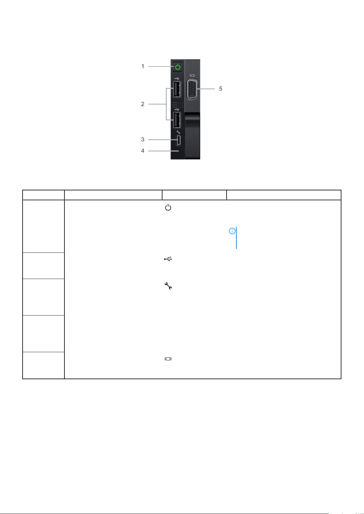
Figure 7. Right control panel
Table 9. Right control panel
Item Indicator, button, or connector Icon Description
1 Power button
2
3
4
5
USB port
iDRAC Direct (Micro-AB USB) The iDRAC Direct (Micro-AB USB) port
iDRAC Direct (Micro-AB USB) LED N/A The iDRAC Direct (Micro-AB USB) LED
VGA port
Indicates if the system is powered on or off.
Press the power button to manually power
on or off the system.
NOTE: Press the power button to
gracefully shut down an ACPI-compliant
operating system.
The USB ports are 4-pin, 2.0-compliant.
These ports enable you to connect USB
devices to the system.
enables you to access the iDRAC Direct
(Micro-AB) features. For more information,
see the iDRAC User’s Guide at Dell.com/
idracmanuals.
indicator lights up to indicate that the
iDRAC Direct port is connected. For more
information, see the iDRAC Direct LED
indicator codes section.
Enables you to connect a display device to
the system. For more information, see the
Technical specifications section.
iDRAC Direct LED indicator codes
The iDRAC Direct LED indicator lights up to indicate that the port is connected and is being used as a part of the iDRAC
subsystem.
You can configure iDRAC Direct by using a USB to micro USB (type AB) cable, which you can connect to your laptop or tablet.
The following table describes iDRAC Direct activity when the iDRAC Direct port is active:
16
Chassis overview
Page 17
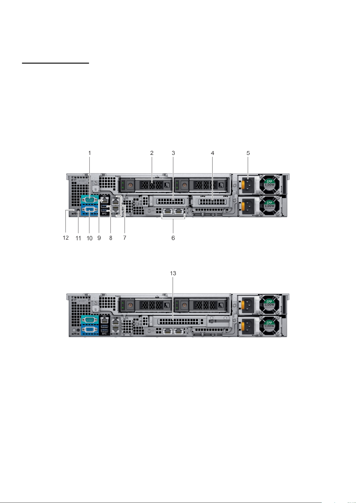
Table 10. iDRAC Direct LED indicator codes
iDRAC Direct LED
indicator code
Solid green for two
seconds
Flashing green (on for
two seconds and off for
two seconds)
Turns off Indicates that the laptop or tablet is unplugged.
Condition
Indicates that the laptop or tablet is connected.
Indicates that the laptop or tablet connected is recognized.
Back panel features
Figure 8. Back panel features of 12 x 3.5 inch + 2 x 3.5 inch (rear) drive system
Figure 9. Back panel features of 12 x 3.5 inch + 2 x 3.5 inch (rear) drive system
Chassis overview
17
Page 18
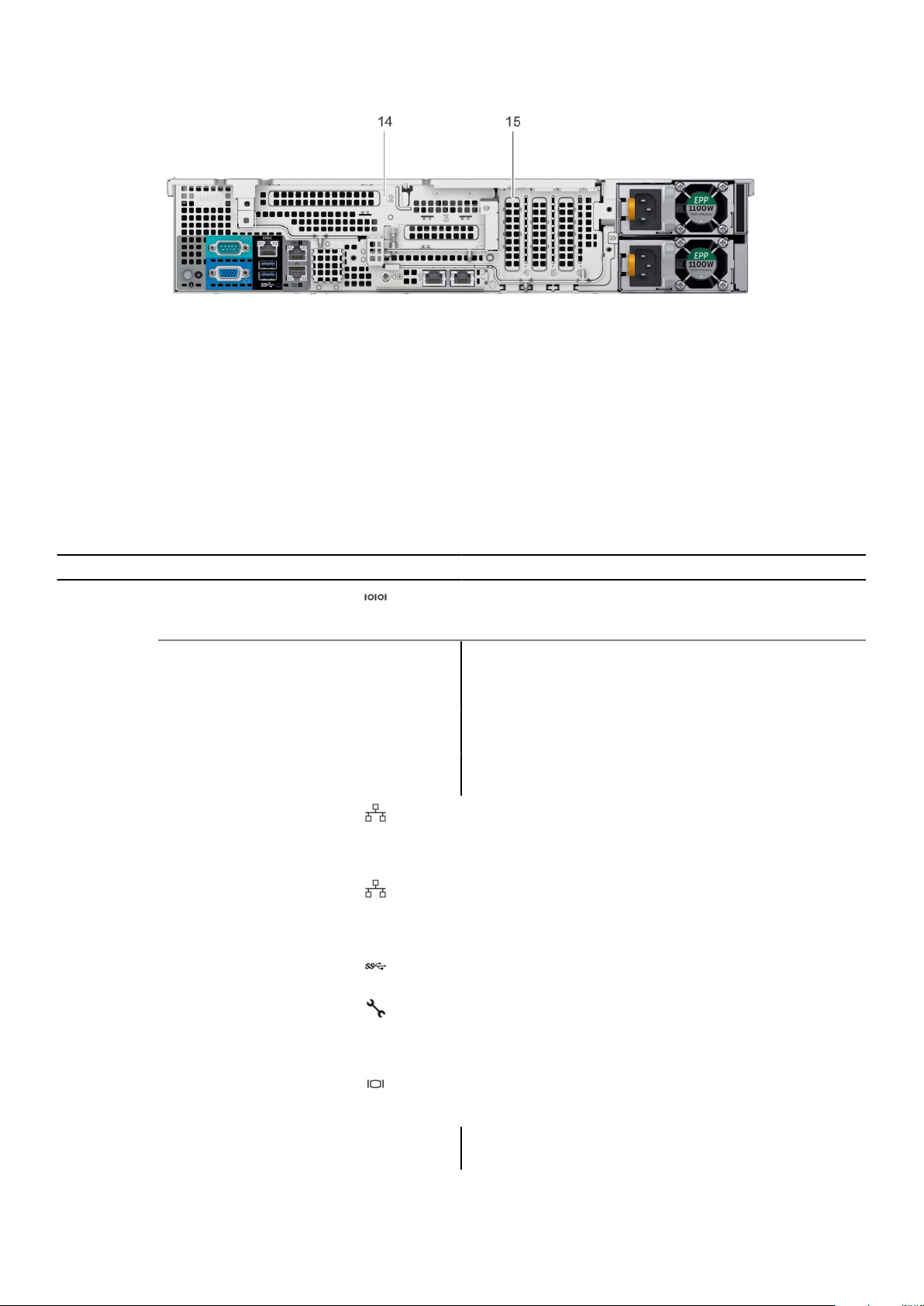
Figure 10. Back panel features of 12 x 3.5 inch drive system with butterfly riser
1. Serial port 2. Drive (rear)
3. Low profile riser right slot 4. Low profile riser left slot
5. Power supply unit (PSU) 6. LOM riser ports
7. Ethernet ports 8. USB 3.0 ports
9. iDRAC9 dedicated network port 10. VGA port
11. CMA power port 12. System identification button
13. Full height riser slot 14. Butterfly riser slot
15. PCIe slot
Table 11. Back panel features of R540
Item Features Icon Description
1 Serial port Use the serial port to connect a serial device to the system.
For more information about the supported serial port, see the
Technical specifications section.
2
3 Low profile riser right slot N/A Use the card slot to connect half-height PCIe expansion card
4 Low profile riser left slot N/A Use the card slot to connect half-height PCIe expansion card
5 Power supply unit (PSU) N/A For information about supported PSUs, see the Technical
6 LOM riser ports Use the Ethernet or SFP+ ports to connect Local Area
7 Ethernet ports (2) Use the Ethernet ports to connect Local Area Networks
8 USB 3.0 port Use the USB 3.0 port to connect USB devices to the system.
9 iDRAC9 dedicated network
10 VGA port Use the VGA port to connect a display to the system. For
11 CMA power port N/A The Cable Management Arm (CMA) power port enables you
Drive N/A Two optional rear drives supported for 12 x 3.5 inch system.
on low profile riser.
on low profile riser.
specifications section.
Networks (LANs) to the system. For more information about
the supported Ethernet or SFP+ ports, see the Technical
specifications section.
(LANs) to the system. For more information about the
supported Ethernet ports, see the Technical specifications
section.
These ports are 4-pin, USB 3.0-compliant.
Use the iDRAC9 dedicated network port to securely access
port
the embedded iDRAC on a separate management network, see
the Integrated Dell Remote Access Controller User’s Guide at
Dell.com/idracmanuals.
more information about the supported VGA port, see the
Technical specifications section.
to connect to the CMA.
18 Chassis overview
Page 19

Table 11. Back panel features of R540 (continued)
Item Features Icon Description
12 System identification button Press the system ID button:
● To locate a particular system within a rack.
● To turn the system ID on or off.
To reset iDRAC, press and hold the button for more than 15
seconds.
NOTE:
● To reset iDRAC using system ID, ensure that the
system ID button is enabled in the iDRAC setup.
● If the system stops responding during POST, press and
hold the system ID button (for more than five seconds)
to enter the BIOS progress mode.
13 Full height riser slot Use the card slots to connect full-height PCIe expansion cards
on full height riser.
14 Butterfly riser slot Use the card slots to connect full-height PCIe expansion cards
on butterfly riser.
15 PCIe slot Use the card slots to connect up to three half-height PCIe
expansion cards on the system board.
Inside the system
NOTE: Components that are hot swappable are marked orange and touch points on the components are marked blue.
Chassis overview 19
Page 20
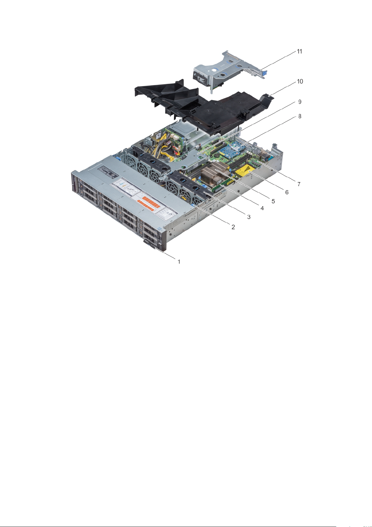
Figure 11. Inside the system without rear drive cage
20
Chassis overview
Page 21

Figure 12. Inside the system with rear drive cage
Information tag 2. Drive backplane
1.
3. Cooling fans 4. Memory module
5. CPU 1 6. CPU 2
7. System board 8. LOM riser card
9. Internal PERC riser 10. Air shroud
11. Butterfly riser 12. Air shroud (12 x 3.5 inch + 2 x 3.5 inch rear hard drive
system)
13. Low profile riser right 14. Low profile riser left
15. Drive cage (rear)
Security features
The latest generation of PowerEdge servers has the features listed in the table to help ensure the security of your data center.
Table 12. Security features
Security feature Description
Cover latch The system cover contains a non-keyed locking mechanism integrated into the latch.
Bezel A standard bezel is an optional metal bezel mounted to the chassis front and shows the Dell EMC
ID. A lock on the bezel protects unauthorized access to hard drives. The system status remains
viewable when the bezel installed.
TPM The Trusted Platform Module (TPM) is used to generate/store keys, protect/authenticate
passwords, and create/store digital certificates. TPM 1.2, 2.0 and China 2.0 is supported.
Power-off security The power button functionality can be disabled in the system BIOS for added security.
Intrusion detection
switch
An internal intrusion detection switch allows users to be alerted with pop-up screen message when
the system cover has been removed.
Chassis overview 21
Page 22

Table 12. Security features (continued)
Security feature Description
Secure mode The system BIOS features an option to enter the secure boot mode through system setup. This
mode includes options to lock out the power button or set up a system password.
22 Chassis overview
Page 23

4
Processors
The Dell EMC PowerEdge R540 featuring the 2nd Generation Intel® Xeon® Scalable processor family offers versatility across
diverse workloads. These processors are designed for next-generation data centers running on software defined infrastructure
and are supercharged for efficiency, performance, and agile services delivery across cloud-native and traditional applications.
The 2nd Generation Intel® Xeon® scalable processor family supports workloads for cloud computing, high-performance
computing, networking, and storage for data centers.
Processor features
The 2nd Generation Intel® Xeon® Processor Scalable Family provides the foundation for a powerful data center platform. It is
the most advanced compute core featuring a new core micro architecture optimized to accelerate a wide range of compute
workloads. The key features are as follows:
● Higher Per-Core Performance: Up to 28 cores (20 cores with R540), delivery high performance, and scalability for
compute-intensive workloads across compute, storage, and network usages. The 2nd Generation Intel® Xeon® Scalable
Processors can offer even greater core or frequencies, or both.
● Greater Memory Bandwidth/Capacity: 50% increased memory bandwidth and capacity. 6 memory channels vs. 4 memory
channels of previous generation for memory intensive workloads.
● Expanded I/O: 48 lanes of PCIe 3.0 bandwidth and throughput for demanding I/O-intensive workloads.
● Intel Ultra Path Interconnect (UPI): Up to three Intel UPI channels increase scalability of the platform to as many as
eight sockets, and improves inter-CPU bandwidth for I/O intensive workloads.
● Intel Advanced Vector Extensions 512 (Intel AVX-512) with a single AVX512 fused multiply add (FMA) execution units.
SKUs which support Advanced RAS enable a second FMA execution unit.
● Security without Compromise: Near-zero encryption overhead enables higher performance on all secure data transactions
with enhanced hardware mitigation.
● Intel Deep Learning Boost: Accelerate data-intensive workloads within the CPU with inferencing capabilities.
Topics:
• Supported processors
• Chipset
Supported processors
NOTE: For more information about Intel Xeon Scalable Processors, see www.intel.com.
Table 13. Supported Processors for R540
Processor number TDP (W) Core count Segment
6126 125 12 Gold
6130 125 16 Gold
6138 125 20 Gold
6226 125 12 Gold
6222V 115 20 Gold
6209U 125 20 Gold
6230 125 20 Gold
5122 105 4 Gold
Processors 23
Page 24

Table 13. Supported Processors for R540 (continued)
Processor number TDP (W) Core count Segment
5118 105 12 Gold
5120 105 14 Gold
5117 105 10 Gold
5220 125 18 Gold
5218 125 16 Gold
5222 105 4 Gold
5215 85 10 Gold
5217 115 8 Gold
5218R 125 20 Gold
4112 85 4 Silver
4108 85 8 Silver
4110 85 8 Silver
4114 85 10 Silver
4116 85 12 Silver
4214 85 12 Silver
4214R 100 12 Silver
4215 85 8 Silver
4216 100 16 Silver
4208 85 8 Silver
4210 85 10 Silver
4210R 100 10 Silver
3104 85 6 Bronze
3106 85 8 Bronze
3206R 85 8 Bronze
3204 85 6 Bronze
Processor Configurations
The R540 supports two processors with up to 28 cores per processor.
Single CPU Configuration
The R540 functions normally if there is just a single processor that is placed in the processor 1 socket. The system will not boot
if only processor 2 socket is populated. With single processor configuration, only the right riser will be functional.
Processor Installation
For processor installation instructions, see the Disassembly and reassembly section.
24
Processors
Page 25

Chipset
The DELL EMC PowerEdge R540 use the Intel C620 series chipset (PCH) that provides extensive I/O support. Functions and
capabilities include:
● ACPI Power Management Logic Support, Revision 4.0a
● PCI Express Base Specification Revision 3.0
● Integrated Serial ATA host controller supports data transfer rates of up to 6 Gb/s on all ports.
● xHCI USB controller with super speed USB 3.0 ports
● Direct Media Interface
● Enhanced Serial Peripheral Interface
● Flexible I/O - Allows some high-speed I/O signals to be configured as PCIe root ports, PCIe uplink for use with certain PCH
SKUs, SATA (and sSATA), or USB 3.0.
● General Purpose Input Output (GPIO)
● Low Pin Count interface, interrupt controller, and timer functions
● System Management Bus Specification, Version 2.0
● Integrated Clock Controller or Real-Time Clock Controller
● Intel High Definition Audio and Intel Smart Sound Technology
● Integrated 10/100/1000 Mbps Ethernet MAC
● Supports Intel Rapid Storage Technology Enterprise
● Supports Intel Active Management Technology and Server Platform Services
● Supports Intel Virtualization Technology for Directed I/O
● Supports Intel Trusted Execution Technology
● JTAG Boundary Scan support
● Intel QuickAssist Technology
● Intel Trace Hub for debug
For more information, go to Intel.com
Processors
25
Page 26

System memory
NOTE: 768 GB max memory is recommended for performance optimized configurations.
Supported DIMM types are:
● RDIMMs (Registered DIMM) - Provides for higher capacity options and advanced RAS features. It is the most commonly
used DIMM type, and offers the best mix of frequency, capacity, and rank structure choices. LRDIMMs (Load Reduced
DIMM) - Provides maximum capacity beyond that of an RDIMM but at a higher power consumption. Uses a buffer to reduce
memory loading to a single load on all DDR signals, allowing for greater density.
● LRDIMMs (Load Reduced DIMM) - Provides maximum capacity beyond that of an RDIMM but at a higher power
consumption. Uses a buffer to reduce memory loading to a single load on all DDR signals, allowing for greater density.
Supported memory
Table 14. Supported Memory
Feature R540 (DDR4)
DIMM type RDIMM, LRDIMM
5
Transfer speed 2666 MT/s
2400 MT/s
2133 MT/s
1866 MT/s
Voltage 1.2 V
Memory speed
The R540 supports memory speeds of 2666 MT/s, 2400 MT/s, 2133 MT/s, and 1866MT/s depending on the DIMM types
installed and the configuration. The default speed is the highest common supported speed between the CPUs and DIMMs. The
operating speed of the memory is also determined by the maximum speed that is supported by the processor, the speed settings
in the BIOS, and the operating voltage of the system.
Table 15. DIMM Performance Details
DIMM type DIMM ranking Capacity DIMM rated voltage, speed The 2nd Generation Intel®
RDIMM 1R/2R 8 GB, 16 GB,
32 GB
LRDIMM 2R 64 GB DDR4 (1.2 V), 2666 2666 MT/s 2666 MT/s
DDR4 (1.2 V), 2666 2666 MT/s 2666 MT/s
Xeon® Processor scalable
processor family
1 DPC 2 DPC
Topics:
• General memory module installation guidelines
26 System memory
Page 27

General memory module installation guidelines
Memory Configurations
NOTE: Memory configurations that fail to observe these guidelines can prevent system from booting, stop responding
during memory configuration, or operating with reduced memory.
The PowerEdge R540 system support flexible memory configurations ranging from capacities of 8 GB to 1 TB. CPU1 supports
up to 10 DIMMs. CPU2 supports up to 6 DIMMs. The R540 system supports memory configuration according to the following
population rules:
● Mixing DIMMs with different rank is supported with condition of not more than two different ranks of DIMMs can be
installed in a system.
● Speed: If memory modules with different speeds are installed, they operate at the speed of the slowest installed memory
module(s) or slower depending on the system DIMM configuration.
● DIMMs with different data widths can be mixed. DIMMs with x4 and x8 data widths are supported and mixing is allowed.
● When mixing memory modules with different capacities, populate the sockets with memory modules with highest capacity
first. For example, slot A1 populated first, then A2, and so on… The second CPU mirrors the first CPU population.
Memory RAS features
Reliability, availability, and serviceability (RAS) features help keep the system online and operational without significant impact
to performance, and can decrease data loss and being unresponsive due to errors. RAS aids in rapid, accurate diagnosis of faults
which require service.
Table 16. Supported RAS features
Feature Description
Dense configuration optimized profile Increased memory reliability can be a result from this
selectable platform profile that adjusts parameters to reduce
faults regarding refresh rates, speed, temperature, and
voltage.
Memory demand and patrol scrubbing Demand scrubbing is the ability to write corrected data back
to the memory once a correctable error is detected on a read
transaction. Patrol scrubbing proactively searches the system
memory, repairing correctable errors.
Recovery from single DRAM device failure (SDDC) Recovery from Single DRAM Device Failure (SDDC) provides
error checking and correction that protects against any single
memory chip failure and multi bit errors from any portion of a
single memory chip.
Failed DIMM isolation This feature provides the ability to identify a specific failing
DIMM channel pair, thereby enabling the user to replace only
the failed DIMM pair.
Memory mirroring Memory mirroring is a method of keeping a duplicate
(secondary or mirrored) copy of the contents of memory as a
redundant backup for use if the primary intra-socket memory
fails. The mirrored copy of the memory is stored in memory of
the same processor socket.
Memory address parity protection This feature provides the ability to detect transient errors on
the address lines of the DDR channel.
Memory sparing (rank) Memory sparing allocates one rank per channel as a spare. If
excessive correctable errors occur in a rank or channel, they
are moved to the spare area while the operating system is
running to prevent the errors from causing an uncorrectable
failure.
System memory 27
Page 28

Table 16. Supported RAS features (continued)
Feature Description
Memory thermal throttling This feature helps to optimize power/performance and can
also be used to prevent DIMMs from overheating.
28 System memory
Page 29

6
Storage
The PowerEdge R540 provide scalable storage that allows you to adapt to your workload and operational demands. R540
supports up to 12 x 3.5 or 2.5 inches in 3.5-inch adapter front access hard drives, with optional 2 x 3.5-inch rear drive
configuration. With comprehensive storage options, the R540 offer various internal and external storage controllers, supports
different drive types, chassis, backplanes, and varied numbers of drives.
Storage controllers
Dell EMC's RAID controller options offer performance improvements, including the Mini PERC solution. Mini PERC provides a
base RAID hardware controller that is installed on a dedicated PCIe slot. It is installed on the dedicated PCIe slot using a small
form factor and high-density connector on the system board.
The new PERC controller offerings leverage heavily on previous generation PERC family. The premium performance PERC series
controller drives better IOPs and enhanced the SSD performance.
Table 17. PERC series controller offerings
Performance
level
Entry
Value
Value
performance
Premium
performance
Controller and description
S140 (SATA, NVMe)
HBA330, H330
12 Gbps SAS HBA
H730P
H740P, H840
Supported drives - SAS and SATA
The PowerEdge R440 system supports internal drives:
● Up to 14 x 3.5 inch hot-swappable HDDs or 2.5 inch hot-swappable SSDs or HDDs using hybrid carrier to fit in the 3.5 inch
drive bay [12 x 3.5 inch front accessible + 2 x 3.5 inch rear accessible] .
● Up to 12 x 3.5 inch hot-swappable HDDs or 2.5 inch hot-swappable SSDs or HDDs using hybrid carrier to fit in the 3.5 inch
drive bay .
● Up to 8 x 3.5 inch hot-swappable HDDs or 2.5 inch hot-swappable SSDs or HDDs using hybrid carrier to fit in the 3.5 inch
drive bay .
Topics:
• IDSDM with vFlash card
• Optical Drives
• Tape Drives
• Boot Optimized Storage Subsystem
IDSDM with vFlash card
The PowerEdge R540 system supports Internal Dual SD module (IDSDM) and vFlash card. In the current generation of
PowerEdge servers, IDSDM and vFlash card are combined into a single card module, and are available in these configurations:
Storage 29
Page 30

● vFlash or
● IDSDM or
● vFlash and IDSDM
The IDSDM/vFlash card sits in the back of the system, in a Dell-proprietary slot. IDSDM/vFlash card supports three micro SD
cards (two cards for IDSDM and one card for vFlash). Micro SD cards capacity for IDSDM is 16/32/64 GB while for vFlash the
micro SD card capacity is 16 GB.
Boot Optimized Storage Subsystem (BOSS)
BOSS is a simple RAID solution card that is designed specifically for booting the system's operating system, which supports up
to two 6 Gbps M.2 SATA drives. This card has a x8 connector using PCIe gen 2.0 x2 lanes, available only in the low-profile and
half-height form factor.
Optical Drives
The PowerEdge R540 supports one of the following internal optical drive options:
● DVD-ROM
● DVD+ROM
Tape Drives
The R540 do not support internal tape drives. However, external tape backup devices are supported on R540.
Supported external tape drives:
● External RD1000 USB
● External LTO-5, LTO-6, LTO-7 and 6 Gb SAS tape drives
● 114X rack mount chassis with LTO-5, LTO-6, and LTO-7 6Gb SAS tape drives
● TL1000 with LTO-5, LTO-6, and LTO-7 6 Gb SAS and 8GB FC tape drives
● TL2000 with LTO-5, LTO-6, and LTO-7 6 Gb SAS and 8GB FC tape drives
● TL4000 with LTO-5, LTO-6, and LTO-7 6 Gb SAS and 8GB FC tape drives
● ML6000 with LTO-5, LTO-6, and LTO-7 6 Gb SAS and 8GB FC tape drives
Boot Optimized Storage Subsystem
The Boot Optimized Storage Subsystem (BOSS) is an alternative, high speed location to install the operating system. This
ensures that the drive based storage is not used by the operating system. BOSS is a simple RAID solution card designed
specifically for booting the system's operating system, which supports up to two 6 Gbps M.2 SATA drives. This card has a x8
connector using PCIe gen 2.0 x2 lanes, available only in the low-profile and half-height form factor.
NOTE:
The BOSS is recommended for non-virtualized operating systems. Virtualized operating systems are best supported
by the IDSDM.
BOSS is an half height PCIe M.2 SATA carrier card that installed on a PCIe slot to draw power and provide system management
bus sideband access into the BOSS's thermal field replacement unit (TFRU). The TFRU controls BOSS's localized active cooling
fan solution and provide status to iDRAC. SATA data is exposed via the NPIO connector that is cabled to the system board or
backplane.
30
Storage
Page 31

Figure 13. Boot Optimized Storage Subsystem (BOSS)
Table 18. BOSS RAID controller features
Function/Feature Supported
Stripe size supported 64k
Configuration (HII) Yes
Full initialization No
Fast initialization Yes
NOTE: Performed on virtual disk creation by default.
Background initialization No
Storage 31
Page 32

7
Networking and PCIe
The Dell EMC PowerEdge R540 offers balanced, scalable I/O capabilities, including integrated PCIe 3.0-capable expansion slots.
The Lan On Motherboard(LOM) option enable you to choose the right network fabric without using up a valuable PCI slot.
Topics:
• LAN on Motherboard(LOM)
• PCIe Expansion cards
LAN on Motherboard(LOM)
The Dell EMC PowerEdge R540 system supports two 1 Gbps on board Network Interface Controller (NIC) ports on the back
panel. The R540 also supports extra two optional NIC ports with following LOM options:
● Two 1GbE ports
● Two 10GbE ports
● Two 10GbE SFP+ ports
PCIe Expansion cards
The PowerEdge R540 system supports up to five PCI express (PCIe) generation 3 expansion cards slots plus 1x LOM riser slot.
Supported risers for R540.
1. LOM riser
2. Right riser
3. Left riser
4. Butterfly riser
Below are PCIe slots configuration supported by R540:
Figure 14.
Figure 15. Configuration B: LOM riser + Right riser + 2 x 3.5 inch rear hard drive
32 Networking and PCIe
Page 33

Figure 16. Configuration C: LOM riser + Left riser + Right riser + 2 x 3.5 inch rear hard drive
Figure 17. Configuration D: LOM riser + Butterfly riser + 3 x low profile slot
Networking and PCIe 33
Page 34

Trusted platform module
The Trusted Platform Module (TPM) is used to generate and store keys, protect or authenticate passwords, and create
and store digital certificates. The Intel’s TXT (Trusted Execution Technology) functionality along with Microsoft’s Platform
Assurance feature in Windows Server 2016 is supported. TPM can also be used to enable the BitLocker hard drive encryption
feature in Windows Server 2012/2016.
The TPM chip is on the Plug-in Module (PIM) and bound only to one system board.
The system board has a connector for the plug-in module, and it is factory-installed.
There are four types of TPM module options:
● No TPM
● TPM 1.2
● TPM 2.0
8
34 Trusted platform module
Page 35

Video specifications
The PowerEdge R540 system supports Matrox G200eW3 graphics card.
Table 19. Supported video resolution options
Resolution Refresh Rate Horizontal Freq. Pixel Clock
1024 x 768 60 Hz 48.4 kHz 65.0 MHz
1280 x 800 60 Hz 49.7 kHz 83.5 MHz
1280 x 1024 60 Hz 64.0 kHz 108.0 MHz
1360 x 768 60 Hz 47.71 kHz 85.5 MHz
1440 x 900 60 Hz 55.9 kHz 106.5 MHz
1600 x 900 60 Hz (RB) 55.54 kHz 97.75 MHz
1600 x 1200 60 Hz 75.0 kHz 162.0 MHz
1680 x 1050 60 Hz (RB) 64.7 kHz 119.0 MHz
1920 x 1080 60 Hz 67.158 kHz 173.0 MHz
9
1920 x 1200 60 Hz 74.556 kHz 193.25 MHz
Video specifications 35
Page 36

10
Power, Thermal, and Acoustics
The lower overall system-level power draw is a result of the breakthrough system design developed by Dell EMC. The system
aims to maximize performance per watt through a combination of energy efficient technologies, optimized thermal designs and
intelligent fan control algorithms. The system fan control algorithms use an extensive array of sensors that automatically monitor
power and thermal activity to minimize fan speeds based on system cooling requirements, reducing the power required for
cooling.
Topics:
• Power consumption and energy efficiency
• Power supply units
• Thermal and Acoustics
Power consumption and energy efficiency
With the rise in the cost of energy that is coupled with increasing data center density, Dell EMC provides tools and technologies
to help you realize greater performance with lower energy cost and wastage. More efficient data center usage can reduce costs
by slowing the need for additional data center space. The following table lists the tools and technologies that Dell EMC offers to
help you achieve your data center goals by lowering power consumption and increasing energy efficiency.
Table 20. Power tools and technologies
Feature Description
Power supply units (PSU) portfolio PSU portfolio includes intelligent features such as dynamically
optimizing efficiency while maintaining availability and
redundancy.
Tools for right-sizing Enterprise Infrastructure Planning Tool (EIPT) is a tool
that helps you to plan and tune your computer and
infrastructure equipment for maximum efficiency. EIPT helps
you by calculating hardware power consumption, power
infrastructure, and storage. You can learn more at Dell.com/
calc
Industry compliance Dell EMC's servers are compliant with all relevant industry
certifications and guidelines, including 80 PLUS, Climate
Savers, and ENERGY STAR.
Power monitoring accuracy PSU power monitoring improvements include:
● Power monitoring accuracy of 1%, whereas the industry
standard is 5%
● More accurate reporting of power
● Better performance under a power cap
Power capping Use Dell EMC's systems management to set the power cap
limit for your systems to limit the output of a PSU and
reduce system power consumption. Dell is the first hardware
vendor to leverage Intel Node Manager for circuit-breaker fast
capping.
Systems management Dell EMC's servers are compliant with all relevant industry
certifications and guidelines, including 80 PLUS, Climate
Savers, and ENERGY STAR.
Dell OpenManage Power Center delivers group power
management at the rack, row, and data center level for
36 Power, Thermal, and Acoustics
Page 37

Table 20. Power tools and technologies (continued)
Feature Description
servers, power distribution units, and uninterruptible power
supplies.
Active power management
Fresh Air cooling
Rack infrastructure
Intel® Node Manager is an embedded technology that
provides individual server- level power reporting and
power limiting functionality. Dell offers a complete power
management solution that is comprised of Intel Node
Manager that is accessed through Dell iDRAC9 Enterprise
and OpenManage Power Center that allows policy- based
management of power and thermals at the individual server,
rack, and data center level. Hot spare reduces power
consumption of redundant power supplies.
Thermal control of fan speed optimizes the thermal settings
for your environment to reduce fan consumption and lower
system power consumption. Idle power enables Dell servers to
run as efficiently when idle as when at full workload.
FAC is supported with certain configuration limitations. With
the thermal design and reliability of Dell products, you
can have the capability to operate at excursion- based
temperatures beyond the industry standard of 35°C (95°F)
without impacting your availability model. This solution
takes into account servers, networking, storage, and other
infrastructure.
Dell EMC offers some of the industry's highest- efficiency
power infrastructure solutions, including:
● Power distribution units (PDUs)
● Uninterruptible power supplies (UPSs)
● Energy smart containment rack enclosures
Power supply units
Energy Smart power supplies have intelligent features, such as the ability to dynamically optimize efficiency while maintaining
availability and redundancy. Also featured are enhanced power-consumption reduction technologies, such as high-efficiency
power conversion and advanced thermal-management techniques, and embedded power-management features including highaccuracy power monitoring. The system supports two hot-swappable AC power supplies with 1 + 1 redundancy, auto-sensing
and auto-switching capability. A single cabled AC power supply option is also available for the R540.
Thermal and Acoustics
The system's thermal management delivers high performance through optimized cooling of components at the lowest fan
speeds across a wide range of ambient temperatures from 10°C to 35°C (50°F to 95°F) and to extended ambient temperature
ranges. These optimizations result in lower fan power consumption which translate to lower system power and data center
power consumption.
Thermal design
The thermal design of the system reflects the following:
● Optimized thermal design: The system layout is architected for optimum thermal design. System component placement
and layout are designed to provide maximum airflow coverage to critical components with minimal expense of fan power.
Power, Thermal, and Acoustics
37
Page 38

● Comprehensive thermal management: The thermal control system regulates the system fan speeds based on feedback
from system component temperature sensors, as well as for system inventory and subsystem power draw. Temperature
monitoring includes components such as processors, DIMMs, chipset, system inlet air temperature and hard disk drives.
● Open and closed loop fan speed control: Open loop fan control uses system configuration to determine fan speed based
on system inlet air temperature. Closed loop thermal control uses temperature feedback to dynamically adjust fan speeds
based on system activity and cooling requirements.
● User-configurable settings: With the understanding and realization that every customer has a unique set of
circumstances or expectations from the system, in this generation of servers, we have introduced limited user-configurable
settings in the iDRAC9 BIOS setup screen. For more information, see the Dell EMC PowerEdge system Installation and
Service Manual on Dell.com/Support/Manuals and “Advanced Thermal Control: Optimizing across Environments and Power
Goals” on Dell.com.
● Cooling redundancy: The system allows N+1 fan redundancy, allowing continuous operation with one fan failure in the
system.
Acoustical design
Dell EMC focuses on sound quality in addition to sound power level and sound pressure level. Sound quality describes how
disturbing or pleasing a sound is interpreted, and Dell EMC references several psychacoustical metrics and thresholds in
delivering to it. Tone prominence is one such metric. Sound power and sound pressure levels increase with greater populations
or higher utilization, while sound quality remains good even as the frequency content changes. A reference for comparison to
sound pressure levels for familiar noise sources is given in the following table. An extensive description of Dell EMC Enterprise
acoustical design and metrics is available in the Dell Enterprise Acoustics white paper.
Table 21. Acoustical reference points and output comparisons
Value measured at your ears Equivalent familiar noise experience
LpA, dBA, re 20 μPa Loudness, sones
90 80 Loud concert
75 39 Data center, vacuum cleaner, voice must be elevated to be
heard
60 10 Conversation levels
45 4 Whispering, open office layout, normal living room
35 2 Quiet office
30 1 Quiet library
20 0 Recording studio
38 Power, Thermal, and Acoustics
Page 39

11
Rack rails
The rail offerings for the R540 consist of two general types: sliding and static
Sliding rails features summary
The sliding rails (two varieties are offered) allow the system to be fully extended out of the rack for service. They are available
with or without the optional cable management arm (CMA).
Figure 18. Sliding rails with optional CMA
ReadyRails-Sliding rails for 4-post racks
● Supports Drop-in Installation of the chassis to the rails.
● Support for tool-less installation in 19" EIA-310-E compliant square or unthreaded round hole 4-post racks including all
generations of the Dell racks.
● Support for tooled installation in 19" EIA-310-E compliant threaded hole 4-post racks.
● Support full extension of the system out of the rack to allow serviceability of key internal components.
● Support for optional cable management arm (CMA).
● Minimum rail mounting depth without the CMA: 714 mm.
● Minimum rail mounting depth with the CMA: 845 mm.
● Square-hole rack adjustment range: 631-868 mm.
● Round-hole rack adjustment range: 617-861 mm.
● Threaded-hole rack adjustment range: 631-883 mm.
Stab-in/Drop-in sliding rails for 4-post racks (New for 14G systems)
● Supports drop-in or stab-in installation of the chassis to the rails.
● Support for tool-less installation in 19" EIA-310-E compliant square, unthreaded round hole racks including all generations of
the Dell racks. Also supports tool-less installation in threaded round hole 4-post racks.
● Required for installing R540 in a Dell EMC Titan or Titan-D rack.
● Support full extension of the system out of the rack to allow serviceability of key internal components.
● Support for optional cable management arm (CMA).
● Minimum rail mounting depth without the CMA: 714 mm.
Rack rails 39
Page 40

● Minimum rail mounting depth with the CMA: 845 mm.
● Square-hole rack adjustment range: 603-915 mm.
● Round-hole rack adjustment range: 603-915 mm.
● Threaded-hole rack adjustment range: 603-915 mm.
Static rails
The static rails support a wider variety of racks than the sliding rails. However, they do not support serviceability in the rack and
are thus not compatible with the CMA.
Figure 19. Static rails
Static rails features summary
Static Rails for 4-post & 2-post Racks:
● Supports Stab-in installation of the chassis to the rails.
● Support tool-less installation in 19" EIA-310-E compliant square or unthreaded round hole 4-post racks including all
generations of Dell racks.
● Support tooled installation in 19" EIA-310-E compliant threaded hole 4-post and 2-post racks.
● Minimum rail mounting depth: 622 mm.
● Square-hole rack adjustment range: 608-879 mm.
● Round-hole rack adjustment range: 594-872 mm.
● Threaded-hole rack adjustment range: 608-890 mm.
NOTE: One key factor in selecting the proper rails is identifying the type of rack in which they are installed.
2-Post racks installation
If installing to 2-Post (Telco) racks, the ReadyRails Static rails (B4) must be used. Both sliding rails support mounting in 4-post
racks only.
40
Rack rails
Page 41

Figure 20. Static rails in 2-post center mount configuration
Installation in the Dell EMC Titan or Titan-D racks
If installing to Titan or Titan-D racks, the Stab-in/Drop-in Sliding rails (B13) must be used. This rail collapses down sufficiently to
fit in racks with mounting flanges spaced about 24 inches apart from front to back. The Stab-in/Drop-in Sliding rail allows bezels
of the servers and storage systems to be in alignment when installed in these racks.
System-to-Rail Installation Method
If the customer prefers to use the stab-in installation method for installing their systems to the rails, the Stab-in/Drop-in Sliding
rails(B13) or the ReadyRails Static rail (B4) must be selected.
NOTE: ReadyRails Sliding rails (B6) are drop-in only.
Table 22. Static, Sliding, or Stab-in/Drop-in sliding rails
Rail
identifier
B6 Ready Rails
B13 Stab-in/
B4 Ready Rails
* Minor conversion required
NOTE: No screws are required for the Stab-in/Drop-in Sliding (B13) rails when mounting the rails to the racks
NOTE: Screws are not included in either kit as threaded racks are offered with various thread designations. Users must
therefore provide their own screws when mounting the rails in threaded racks.
NOTE: Screw head diameter for the sliding rails must be 10 mm or less.
Other key factors governing proper rail selection include the following:
● Spacing between the front and rear mounting flanges of the rack
● Type and location of any equipment mounted in the back of the rack such as power distribution units (PDUs)
Rail type Installati
Sliding
Drop-in
Sliding
Static
on
method
Drop-in X √ √ √ * X X
Stab-in/
Drop-in
Stab-in X √ √ √ * √ * √
Supported rack types
Dell EMC
Titan or
Titan-D
Racks
√ √ √ √ X X
4-Post 2-Post
Square Round Thread Flush Center
● Overall depth of the rack
The static rails offer a greater adjustability range and a smaller overall mounting footprint than the sliding rails. This is because
of their reduced complexity and lack of need for CMA support.
Rack rails
41
Page 42

Table 23. Rail Adjustability Range and Rail Depth
Rail
Identifier
B6 Ready
B13 Stab-in/
B4 Ready
* Values represent the distance between the front and rear mounting flanges on the rack
+ Measured from the front surface of the front rack mounting flange
NOTE: For situations where CMA support is not required, the outer CMA mounting brackets can be removed from the
sliding rails to reduce the overall length of the rails and eliminate potential interferences with rear-mounted PDUs or the
rack rear door.
NOTE: For the ReadyRails Sliding rails(B6) and ReadyRails Static rails (B4), the adjustment range of the rails is a function
of the type of rack in which they are being mounted. The Min/Max values listed above represent the allowable distance
between the front and rear mounting flanges in the rack. Rail depth without the CMA represents the minimum depth of the
rail with the outer CMA brackets removed (if applicable) as measured from the front mounting flanges of the rack.
Rail Type Rail Adjustability Range (mm)* Rail Depth (mm)+
Rails
Sliding
Drop-in
Sliding
Rails Static
Square Round Threaded Without
Min Max Min Max Min Max
676 868 662 861 676 883 714 845
603 915 603 915 603 915 714 845
608 879 594 872 604 890 622 N/A
CMA
With CMA
Cable management arm (CMA)
The optional cable management arm (CMA) organizes and secures the cords and cables exiting the back of the systems. It
unfolds to allow the systems to extend out of the rack without having to detach the cables. Some key features of the CMA
include:
● Large U-shaped baskets to support dense cable loads.
● Open vent pattern for optimal airflow.
● Ability to be mounted on either side by simply swinging the spring-loaded brackets from one side to the other.
● Utilizes hook-and-loop straps rather than plastic tie wraps to eliminate the risk of cable damage during cycling.
● Includes a low-profile fixed tray to both support and retain the CMA in its fully closed position.
● Both the CMA and the tray mount without the use of tools via simple and intuitive snap-in designs.
The CMA can be mounted to either side of the sliding rails without the use of tools or the need for conversion. However, it is
recommended that it be mounted on the side opposite to the power supplies to allow easier access to the power supplies and
rear hard drives (if applicable) for service or replacement.
Figure 21. Sliding rails with CMA
42
Rack rails
Page 43

Rack Installation
The R540 offers two different varieties of sliding rails: ReadyRail Sliding rails (B6), and combination Stab-in/Drop-in Sliding rails
(B13). Only one variety of static rail is offered: ReadyRails Static rails (B4).
A "drop-in" design means that the system is installed vertically into the rails by inserting the standoffs on the sides of the
system into the "J-slots" in the inner rail members with the rails in the fully extended position. The recommended method of
installation is to first insert the rear standoffs on the system into the rear J-slots on the rails to free up a hand and then rotate
the system down into the remaining J-slots while using the free hand to hold the rail against the side of the system.
A "stab-in" design means that the inner (chassis) rail members must first be attached to the sides of the system and then
inserted into the outer (cabinet) members installed in the rack. For 2U systems, it is recommended that two people perform this
operation.
NOTE: The 2U system requires two people for installation due to its heavier weight.
Installing system into the rack (option A: Drop-In)
1. Pull the inner rails out of the rack until they lock into place.
Rack rails
43
Page 44

Figure 22. Pull out inner rail
2. Locate the rear rail standoff on each side of the system and lower them into the rear J-slots on the slide assemblies.
3. Rotate the system downward until all the rail standoffs are seated in the J-slots.
Figure 23. Rail standoffs seated in J-slots
4. Push the system inward until the lock levers click into place.
5. Pull the blue slide release lock tabs forward on both rails and slide the system into the rack until the system is in the rack.
44
Rack rails
Page 45

Figure 24. Slide system into the rack
Installing the system into the rack (option B: Stab-In)
1. Pull the intermediate rails out of the rack until they lock into place.
2. Release the inner rail lock by pulling forward on the white tabs and sliding the inner rail out of the intermediate rails.
Rack rails
45
Page 46

Figure 25. Pull out the intermediate rail
Table 24. Rail component
Number Component
1 Intermediate rail
2 Inner rail
3. Attach the inner rails to the sides of the system by aligning the J-slots on the rail with the standoffs on the system and
sliding forward on the system until they lock into place.
46
Rack rails
Page 47

Figure 26. Attach the inner rails to the system
4. With the intermediate rails extended, install the system into the extended rails.
Rack rails
47
Page 48

Figure 27. Install system into the extended rails
5. Pull the blue slide release lock tabs forward on both the rails, and slide the system into the rack.
Figure 28. Slide system into the rack
48
Rack rails
Page 49

12
Dell EMC OpenManage systems management
Figure 29. Dell EMC OpenManage Portfolio
Dell EMC delivers management solutions that help IT Administrators effectively deploy, update, monitor, and manage IT assets.
OpenManage solutions and tools enable you to quickly respond to problems by helping them to manage Dell EMC servers
effectively and efficiently; in physical, virtual, local, and remote environments, operating in-band, and out-of-band (agent-free).
The OpenManage portfolio includes innovative embedded management tools such as the integrated Dell Remote Access
Controller (iDRAC), Chassis Management Controller and Consoles like OpenManage Enterprise, OpenManage Power Manager
plug in, and tools like Repository Manager.
Dell EMC has developed comprehensive systems management solutions based on open standards and has integrated with
management consoles that can perform advanced management of Dell hardware. Dell EMC has connected or integrated the
advanced management capabilities of Dell hardware into offerings from the industry's top systems management vendors and
frameworks such as Ansible, thus making Dell EMC platforms easy to deploy, update, monitor, and manage.
The key tools for managing Dell EMC PowerEdge servers are iDRAC and the one-to-many OpenManage Enterprise console.
OpenManage Enterprise helps the system administrators in complete lifecycle management of multiple generations of
PowerEdge servers. Other tools such as Repository Manager, which enables simple yet comprehensive change management.
OpenManage tools integrate with systems management framework from other vendors such as VMware, Microsoft, Ansible, and
ServiceNow. This enables you to use the skills of the IT staff to efficiently manage Dell EMC PowerEdge servers.
Topics:
• iDRAC with Lifecycle controller
• Server and Chassis Managers
• Dell EMC consoles
• Automation Enablers
• Integration with third-party consoles
• Connections for third-party consoles
• Dell EMC Update Utilities
• Dell resources
Dell EMC OpenManage systems management 49
Page 50

iDRAC with Lifecycle controller
The integrated Dell Remote Access Controller 9 (iDRAC9) with Lifecycle Controller is embedded within every Dell EMC
PowerEdge server and provides functionality that helps IT administrators deploy, update, monitor, and maintain servers with
no need for any additional software to be installed. iDRAC functions regardless of operating system or hypervisor presence
because from a pre-OS or bare-metal state, iDRAC is ready to work because it is embedded within each server from the factory.
iDRAC features and comparison
The R540 supports the following iDRAC licenses – Basic (default), Express (upgrade) and Enterprise (upgrade).
Table 25. iDRAC feature comparison
Feature iDRAC9 Basic iDRAC9 Express iDRAC9 Express
Interfaces / Standards
iDRAC RESTful API
and Redfish
IPMI 2.0 Yes Yes Yes Yes Yes
DCMI 1.5 Yes Yes Yes Yes Yes
Web-based GUI Yes Yes Yes Yes Yes
RACADM command
line (local/remote)
SMASH-CLP
(SSH-only)
Telnet Yes Yes Yes Yes Yes
SSH Yes Yes Yes Yes Yes
Serial Redirection Yes Yes Yes Yes Yes
WSMan Yes Yes Yes Yes Yes
Network Time
Protocol
Connectivity
Yes Yes Yes Yes Yes
Yes Yes Yes Yes Yes
Yes Yes Yes Yes Yes
No Yes Yes Yes Yes
for Blades
iDRAC9
Enterprise
iDRAC9
Datacenter
Shared NIC (LOM) Yes Yes N/A Yes Yes
Dedicated NIC Yes Yes Yes Yes Yes
VLAN tagging Yes Yes Yes Yes Yes
IPv4 Yes Yes Yes Yes Yes
IPv6 Yes Yes Yes Yes Yes
DHCP Yes Yes Yes Yes Yes
DHCP with zero
touch
Dynamic DNS Yes Yes Yes Yes Yes
OS pass-through Yes Yes Yes Yes Yes
iDRAC Direct Front panel USB
Connection View Yes Yes No Yes Yes
50 Dell EMC OpenManage systems management
No No No Yes Yes
Yes Yes Yes Yes Yes
Page 51

Table 25. iDRAC feature comparison (continued)
Feature iDRAC9 Basic iDRAC9 Express iDRAC9 Express
Connection View LLDP transmit
Security
Role-based
authority
Local users Yes Yes Yes Yes Yes
SSL encryption Yes Yes Yes Yes Yes
Secure Enterprise
Key Manager
IP blocking No Yes Yes Yes Yes
Directory services
(AD, LDAP)
Two-factor
authentication
(smart card)
Single sign-On No No No Yes Yes
PK authentication
(for SSH)
No No No No Yes
Yes Yes Yes Yes Yes
No No No Yes (with SEKM
No No No Yes Yes
No No No Yes Yes
No Yes Yes Yes Yes
for Blades
iDRAC9
Enterprise
license)
iDRAC9
Datacenter
Yes (with SEKM
license)
FIPS 140-2 Yes Yes Yes Yes Yes
Secure UEFI
boot - certificate
management
Lock down mode No No No Yes Yes
Unique iDRAC
default password
Customizable
Security Policy
Banner - login page
Easy Multi Factor
Authentication
Auto Certificate
Enrollment (SSL
Certs)
iDRAC Quick Sync
2 - optional auth
for read operations
iDRAC Quick Sync
2 - add mobile
device number to
LCL
Yes Yes Yes Yes Yes
Yes Yes Yes Yes Yes
Yes Yes Yes Yes Yes
No No No No Yes
No No No No Yes
Yes Yes Yes Yes Yes
Yes Yes Yes Yes Yes
System Erase of
internal storage
devices
Remote Presence
Power control Yes Yes Yes Yes Yes
Yes Yes Yes Yes Yes
Dell EMC OpenManage systems management 51
Page 52

Table 25. iDRAC feature comparison (continued)
Feature iDRAC9 Basic iDRAC9 Express iDRAC9 Express
Boot control Yes Yes Yes Yes Yes
Serial-over-LAN Yes Yes Yes Yes Yes
Virtual Media No No Yes Yes Yes
Virtual Folders No No No Yes Yes
Remote File Share No No No Yes Yes
HTML5 access to
Virtual Console
Virtual Console No No Yes Yes Yes
VNC connection toOSNo No No Yes Yes
Quality/bandwidth
control
Virtual Console
collaboration (up
to six simultaneous
users)
Virtual Console
chat
No No Yes Yes Yes
No No No Yes Yes
No No No (One user only) Yes Yes
No No No Yes Yes
for Blades
iDRAC9
Enterprise
iDRAC9
Datacenter
Virtual Flash
partitions
NOTE: vFlash is not available in iDRAC9 for PowerEdge Rx5xx/Cx5xx.
Group Manager No No No Yes Yes
HTTP / HTTPS
support along with
NFS/CIFS
Power and Thermal
Real-time power
meter
Power thresholds
and alerts
Real-time power
graphing
Historical power
counters
Power capping No No No Yes Yes
Power Center
integration
Temperature
monitoring
No No No Yes Yes
Yes Yes Yes Yes Yes
Yes Yes Yes Yes Yes
No Yes Yes Yes Yes
No Yes Yes Yes Yes
No Yes Yes Yes Yes
No No No Yes Yes
Yes Yes Yes Yes Yes
Temperature
graphing
PCIe airflow
customization
(LFM)
52 Dell EMC OpenManage systems management
No Yes Yes Yes Yes
No No No No Yes
Page 53

Table 25. iDRAC feature comparison (continued)
Feature iDRAC9 Basic iDRAC9 Express iDRAC9 Express
Custom Exhaust
Control
Custom Delta-T
control
System Airflow
Consumption
Custom PCIe inlet
temperature
Health Monitoring
Full agent-free
monitoring
Predictive failure
monitoring
SNMPv1, v2, and
v3 (traps and gets)
Email Alerting No Yes Yes Yes Yes
Configurable
thresholds
No No No No Yes
No No No No Yes
No No No No Yes
No No No No Yes
Yes Yes Yes Yes Yes
Yes Yes Yes Yes Yes
Yes Yes Yes Yes Yes
Yes Yes Yes Yes Yes
for Blades
iDRAC9
Enterprise
iDRAC9
Datacenter
Fan monitoring Yes Yes Yes Yes Yes
Power Supply
monitoring
Memory monitoring Yes Yes Yes Yes Yes
CPU monitoring Yes Yes Yes Yes Yes
RAID monitoring Yes Yes Yes Yes Yes
NIC monitoring Yes Yes Yes Yes Yes
HD monitoring
(enclosure)
Out of
Band Performance
Monitoring
Alerts for excessive
SSD wear
Customizable
settings for
Exhaust
Temperature
Serial Console Logs No No No No Yes
SMART logs for
Storage Drives
Yes Yes Yes Yes Yes
Yes Yes Yes Yes Yes
No No No Yes Yes
Yes Yes Yes Yes Yes
Yes Yes Yes Yes Yes
No No No No Yes
Idle Server
detection
Telemetry
Streaming
Update
No No No No Yes
No No No No Yes
Dell EMC OpenManage systems management 53
Page 54

Table 25. iDRAC feature comparison (continued)
Feature iDRAC9 Basic iDRAC9 Express iDRAC9 Express
Remote agent-free
update
Embedded update
tools
Update from
repository (AutoUpdate)
Schedule update
from repository
Improved PSU
firmware updates
Deployment and Configuration
Local configuration
via F10
Embedded OS
deployment tools
Embedded
configuration tools
Auto-Discovery No Yes Yes Yes Yes
Yes Yes Yes Yes Yes
Yes Yes Yes Yes Yes
No No No Yes Yes
No No No Yes Yes
Yes Yes Yes Yes Yes
Yes Yes Yes Yes Yes
Yes Yes Yes Yes Yes
Yes Yes Yes Yes Yes
for Blades
iDRAC9
Enterprise
iDRAC9
Datacenter
Remote OS
deployment
Embedded driver
pack
Full configuration
inventory
Inventory export Yes Yes Yes Yes Yes
Remote
configuration
Zero-touch
configuration
System Retire/
Repurpose
Server
Configuration
Profile in GUI
Add BIOS
configuration to
iDRAC GUI
Diagnostics, Service, and Logging
Embedded
diagnostic tools
No Yes Yes Yes Yes
Yes Yes Yes Yes Yes
Yes Yes Yes Yes Yes
Yes Yes Yes Yes Yes
No No No Yes Yes
Yes Yes Yes Yes Yes
Yes Yes Yes Yes Yes
Yes Yes Yes Yes Yes
Yes Yes Yes Yes Yes
Part Replacement No Yes Yes Yes Yes
NOTE: After performing part replacement on RAID hardware, and the process is complete for replacing firmware
and configuration, Lifecycle Logs reports double part replacement entries which is expected behavior.
54 Dell EMC OpenManage systems management
Page 55

Table 25. iDRAC feature comparison (continued)
Feature iDRAC9 Basic iDRAC9 Express iDRAC9 Express
Server
Configuration
Backup
Easy Restore
(system
configuration)
Server
Configuration
Restore
Easy Restore Auto
Timeout
NOTE: Server Backup and Restore features are not available in iDRAC9 for PowerEdge Rx5xx/Cx5xx.
LED Health status
indicators
LCD screen
(iDRAC9 requires
optional)
Quick Sync (require
NFC bezel, 13G
only)
No No No Yes Yes
Yes Yes Yes Yes Yes
Yes Yes Yes Yes Yes
Yes Yes Yes Yes Yes
Yes Yes N/A Yes Yes
Yes Yes N/A Yes Yes
N/A N/A N/A N/A Yes
for Blades
iDRAC9
Enterprise
iDRAC9
Datacenter
iDRAC Quick Sync
2 (BLE/Wi-Fi
hardware)
iDRAC Direct (front
USB management
port)
iDRAC Service
Module (iSM)
embedded
iSM to in-band
alert forwarding to
consoles
SupportAssist
Collection
(embedded)
Crash screen
capture
Crash video
capture 1
Agent Free Crash
Video Capture
(Windows only)
Yes Yes Yes Yes Yes
Yes Yes Yes Yes Yes
Yes Yes Yes Yes Yes
Yes Yes Yes Yes Yes
Yes Yes Yes Yes Yes
No Yes Yes Yes Yes
No No No Yes Yes
No No No No Yes
Boot capture No No No Yes Yes
Manual reset for
iDRAC (LCD ID
button)
Yes Yes Yes Yes Yes
Dell EMC OpenManage systems management 55
Page 56

Table 25. iDRAC feature comparison (continued)
Feature iDRAC9 Basic iDRAC9 Express iDRAC9 Express
Remote reset for
iDRAC (requires
iSM)
Virtual NMI Yes Yes Yes Yes Yes
OS watchdog Yes Yes Yes Yes Yes
System Event Log Yes Yes Yes Yes Yes
Lifecycle Log Yes Yes Yes Yes Yes
Enhanced Logging
in Lifecycle
Controller Log
Work notes Yes Yes Yes Yes Yes
Remote Syslog No No No Yes Yes
License
management
Improved Customer Experience
iDRAC -Faster
processor, more
memory
Yes Yes Yes Yes Yes
Yes Yes Yes Yes Yes
Yes Yes Yes Yes Yes
N/A Yes N/A Yes Yes
for Blades
iDRAC9
Enterprise
iDRAC9
Datacenter
GUI rendered in
HTML5
Add BIOS
configuration to
iDRAC GUI
iDRAC support for
SW RAID licensing
N/A Yes N/A Yes Yes
N/A Yes N/A Yes Yes
N/A Yes N/A Yes Yes
Server and Chassis Managers
● Integrated Dell Remote Access Controller (iDRAC)
● iDRAC Service Module (iSM)
Dell EMC consoles
● Dell EMC OpenManage Enterprise
● Dell EMC Repository Manager (DRM)
● Dell EMC OpenManage Enterprise Power Manager plugin to OpenManage Enterprise
● Dell EMC OpenManage Mobile (OMM)
Automation Enablers
● OpenManage Ansible Modules
● iDRAC RESTful APIs (Redfish)
● Standards-based APIs (Python, PowerShell)
● RACADM Command Line Interface (CLI)
● GitHub Scripting Libraries
56
Dell EMC OpenManage systems management
Page 57

Integration with third-party consoles
● Dell EMC OpenManage Integrations with Microsoft System Center
● Dell EMC OpenManage Integration for VMware vCenter (OMIVV)
● Dell EMC OpenManage Ansible Modules
● Dell EMC OpenManage Integration with ServiceNow
Connections for third-party consoles
● Micro Focus and other HPE tools
● OpenManage Connection for IBM Tivoli
● OpenManage Plug-in for Nagios Core and XI
Dell EMC Update Utilities
● Dell System Update (DSU)
● Dell EMC Repository Manager (DRM)
Dell EMC Update Packages (DUP)
●
● Dell EMC Server Update Utility (SUU)
● Dell EMC Platform Specific Bootable ISO (PSBI)
Dell resources
For additional information about white papers, videos, blogs, forums, technical material, tools, usage examples, and other
information, go to the OpenManage page at https://www.dell.com/openmanagemanuals or the following product pages:
Table 26. Dell resources
Resource Location
Integrated Dell Remote Access Controller (iDRAC) https://www.dell.com/idracmanuals
iDRAC Service Module (iSM) https://www.dell.com/support/article/sln310557
OpenManage Ansible Modules https://www.dell.com/support/article/sln310720
OpenManage Essentials (OME) https://www.dell.com/support/article/sln310714
OpenManage Mobile (OMM) https://www.dell.com/support/article/sln310980
OpenManage Integration for VMware vCenter (OMIVV) https://www.dell.com/support/article/sln311238
OpenManage Integration for Microsoft System Center
(OMIMSSC)
Dell EMC Repository Manager (DRM) https://www.dell.com/support/article/sln312652
Dell EMC System Update (DSU) https://www.dell.com/support/article/sln310654
Dell EMC Platform Specific Bootable ISO (PSBI) Dell.com/support/article/sln296511
Dell EMC Chassis Management Controller (CMC) www.dell.com/support/article/sln311283
https://www.dell.com/support/article/sln312177
OpenManage Connections for Partner Consoles https://www.dell.com/support/article/sln312320
OpenManage Enterprise Power Manager https://www.dellemc.com/solutions/openmanage/power-
management.htm
OpenManage Integration with ServiceNow (OMISNOW) Dell.com/support/article/sln317784
NOTE: Features may vary by server. Please refer to the product page on https://www.dell.com/manuals for details.
Dell EMC OpenManage systems management 57
Page 58

Appendix A. Additional specifications
The following sections contain information about additional system specifications.
Topics:
• PSU specifications
• System dimensions
• Chassis weight
• Environmental specifications
PSU specifications
The PowerEdge R540 system supports the following AC or DC power supply units (PSU).
Table 27. PSU specifications
13
PSU Class Heat dissipation
1100 W AC Platinum 4100 BTU/hr 50/60 Hz 100–240 V AC, autoranging
1100 W DC Platinum 4416 BTU/hr 50/60 Hz 200–380 V DC, autoranging
750 W AC Platinum 2891 BTU/hr 50/60 Hz 100–240 V AC, autoranging
750 W AC (Mixed
Mode)
750 W DC Platinum 2902 BTU/hr 50/60 Hz 240 V DC
495 W AC Platinum 1908 BTU/hr 50/60 Hz 100–240 V AC, autoranging
NOTE: Heat dissipation is calculated using the PSU wattage rating.
NOTE: This system is also designed to connect to the IT power systems with a phase-to-phase voltage not exceeding 230
V.
Platinum 2891 BTU/hr
(maximum)
Frequency Voltage
50/60 Hz
100–240 V AC, autoranging
58 Appendix A. Additional specifications
Page 59

System dimensions
Figure 30. Dimensions of the PowerEdge R540 system
Table 28. Dimensions of the PowerEdge R540 system
Xa Xb Y Za (with
482.0 mm
(18.97 inches)
434.0 mm
(17.08 inches)
86.8 mm (3.41
inches)
bezel)
35.84 mm (1.41
inches)
Za (without
bezel)
22 mm (0.87
inches)
Zb Zc
647.07 mm
(25.47 inches)
681.755 mm
(26.84 inches)
Chassis weight
Table 29. Chassis weight
System Maximum weight (with all drives/SSDs)
8 x 3.5 inch 25.4 kg (55.99 lb)
12 x 3.5 inch 29.68 kg (65.43 lb)
Environmental specifications
See Dell EMC PowerEdge R540 installation service manuals on Dell.com/Support for detailed environmental specifications.
Appendix A. Additional specifications
59
Page 60

Appendix B. Standards compliance
Table 30. Industry standard documents
Standard URL for information and specifications
14
ACPI Advance Configuration and Power Interface
Specification, v2.0c
Ethernet IEEE 802.3-2005 standards.ieee.org/getieee802/802.3.html
HDG Hardware Design Guide Version 3.0 for Microsoft
Windows Server
IPMI Intelligent Platform Management Interface, v2.0 intel.com/design/servers/ipmi
DDR4 Memory DDR4 SDRAM Specification jedec.org/standards-documents/docs/jesd79-4.pdf
PCI Express PCI Express Base Specification Rev. 2.0 and 3.0 pcisig.com/specifications/pciexpress
PMBus Power System Management Protocol Specification,
v1.2
SAS Serial Attached SCSI, v1.1 t10.org
SATA Serial ATA Rev. 2.6; SATA II, SATA 1.0a Extensions,
Rev. 1.2
SMBIOS System Management BIOS Reference Specification,
v2.7
TPM Trusted Platform Module Specification, v1.2 and v2.0 trustedcomputinggroup.org
UEFI Unified Extensible Firmware Interface Specification, v2.1 uefi.org/specifications
USB Universal Serial Bus Specification, Rev. 2.0 usb.org/developers/docs
acpi.info
microsoft.com/whdc/system/platform/pcdesign/desguide/
serverdg.mspx
pmbus.info/specs.html
sata-io.org
dmtf.org/standards/smbios
60 Appendix B. Standards compliance
Page 61

Appendix C Additional resources
Table 31. Additional resources
Resource Description of contents Location
15
PowerEdge R540 Installation
Service Manuals
PowerEdge R540 Getting
Started Guide
Rack Installation Instructions This document ships with the rack kits, and provides
Information Update This document ships with the system, is also available in PDF
System Information Label The system information label documents the system board
This manual, available in PDF format, provides the following
information:
● Chassis features
● System Setup program
● System messages
● System codes and indicators
● System BIOS
● Remove and replace procedures
● Troubleshooting
● Diagnostics
● Jumpers and connectors
This guide ships with the system, and is also available in PDF
format. This guide provides the following information:
● Initial setup steps
● Key system features
● Technical specifications
instructions for installing a server in a rack.
format online, and provides information on system updates.
layout and system jumper settings. Text is minimized due
to space limitations and translation considerations. The label
size is standardized across platforms.
Dell.com/Support/Manuals
Dell.com/Support/Manuals
Dell.com/Support/Manuals
Dell.com/Support/Manuals
Inside the system chassis
cover
Quick Resource Locator (QRL) This code on the chassis can be scanned by a phone
application to access additional information and resources for
the server, including videos, reference materials, service tag
information, and Dell contact information.
Energy Smart Solution Advisor
(ESSA)
The Dell online ESSA enables easier and more meaningful
estimates to help you determine the most efficient
configuration possible. Use ESSA to calculate the power
consumption of your hardware, power infrastructure, and
storage.
Inside the system chassis
cover
Dell.com/calc
Appendix C Additional resources 61
Page 62

Appendix D. Support and deployment
Topics:
• Dell EMC ProDeploy Enterprise Suite
• Deployment services
• Dell EMC Remote Consulting Services
• Dell EMC Data Migration Service
• ProSupport Enterprise Suite
• ProSupport Plus
• ProSupport
• ProSupport One for Data Center
• Support Technologies
• Additional professional services
• Dell Education Services
• Dell EMC Global Infrastructure Consulting Services
• Dell EMC Managed Services
16
services
Dell EMC ProDeploy Enterprise Suite
ProDeploy Enterprise Suite gets your server out of the box and into optimized production—fast. Our elite deployment engineers
with broad and deep experience utilizing best-in-class processes along with our established global scale can help you around the
clock and around the globe. From simple to the most complex server installations and software integration, we take the guess
work and risk out of deploying your new server technology.
Figure 31. ProDeploy Enterprise Suite capabilities
NOTE: Hardware installation not applicable on selected software products.
Dell EMC ProDeploy Plus
From beginning to end, ProDeploy Plus provides the skill and scale needed to successfully execute demanding deployments
in today's complex IT environments. Certified Dell EMC experts start with extensive environmental assessments and detailed
migration planning and recommendations. Software installation includes set up of most versions of Dell EMC SupportAssist and
62 Appendix D. Support and deployment services
Page 63

OpenManage system management utilities. Post-deployment configuration assistance, testing, and product orientation services
are also available.
Dell EMC ProDeploy
ProDeploy provides full service installation and configuration of both server hardware and system software by certified
deployment engineers including set up of leading operating systems and hypervisors as well as most versions of Dell EMC
SupportAssist and OpenManage system management utilities. To prepare for the deployment, we conduct a site readiness
review and implementation planning exercise. System testing, validation, and full project documentation with knowledge transfer
complete the process.
Dell EMC Basic Deployment
Basic Deployment delivers worry-free professional installation by experienced technicians who know Dell EMC servers inside and
out.
Dell EMC Residency Services
Residency Services helps customers transition to new capabilities quickly with the assistance of on-site or remote Dell EMC
experts whose priorities and time you control. Residency experts can provide post implementation management and knowledge
transfer related to a new technology acquisition or day-to-day operational management of the IT infrastructure.
Deployment services
Deployment services details and exceptions can be found in service description documents at the Enterprise Configuration and
Deployment pageon Dell.com.
Dell EMC Remote Consulting Services
When you are in the final stages of your PowerEdge server implementation, you can rely on Dell EMC Remote Consulting
Services and our certified technical experts to help you optimize your configuration with best practices for your software,
virtualization, server, storage, networking, and systems management.
Dell EMC Data Migration Service
Protect your business and data with our single point of contact to manage your data migration project. Your project manager will
work with our experienced team of experts to create a plan using industry-leading tools and proven processes based on global
best practices to migrate your existing files and data so your business system get up and running quickly and smoothly.
ProSupport Enterprise Suite
With Dell EMC ProSupport Services, we can help you keep your operation running smoothly, so you can focus on running your
business. We will help you maintain peak performance and availability of your most essential workloads. Dell EMC ProSupport
is a suite of support services that enable you to build the solution that is right for your organization. Choose support models
based on how you use technology and where you want to allocate resources. From the desktop to the data center, address
everyday IT challenges, such as unplanned downtime, mission-critical needs, data and asset protection, support planning,
resource allocation, software application management and more. Optimize your IT resources by choosing the right support
model.
Appendix D. Support and deployment services
63
Page 64

Figure 32. ProSupport Enterprise Suite
ProSupport Plus
When you purchase PowerEdge servers, we recommend ProSupport Plus, our proactive and preventative support, for businesscritical systems. ProSupport Plus provides all the benefits of ProSupport, plus the following:
● An assigned Services Account Manager (SAM) who knows your business and your environment
● Access to senior ProSupport engineers for faster issue resolution
● Personalized, preventive recommendations based on analysis of support trends and best practices from across the Dell EMC
customer base to reduce support issues and improve performance
● Predictive analysis for issue prevention and optimization enabled by SupportAssist
● Proactive monitoring, issue detection, notification and automated case creation for accelerated issue resolution enabled by
SupportAssist
● On-demand reporting and analytics-based recommendations enabled by SupportAssist and TechDirect
ProSupport
Our ProSupport service offers highly trained experts around the clock and around the globe to address your IT needs. We will
help you minimize disruptions and maximize availability of your PowerEdge server workloads with:
● 24x7x365 access to certified hardware and software experts
● Collaborative 3rd party support
● Hypervisor and OS support
● Consistent level of support available for Dell EMC hardware, software and solutions
● Onsite parts and labor response options including next business day or four-hour mission critical
ProSupport One for Data Center
ProSupport One for Data Center offers flexible site-wide support for large and distributed data centers with more than 1,000
assets. This offering is built on standard ProSupport components that leverage our global scale but are tailored to your
company's needs. While not for everyone, it offers a truly unique solution for Dell EMC's largest customers with the most
complex environments.
● Team of designated Technology Services Managers with remote, on-site options
● Designated ProSupport One technical and field engineers who are trained on your environment and configurations
● On-demand reporting and analytics-based recommendations enabled by SupportAssist and TechDirect
● Flexible on-site support and parts options that fit your operational model
● A tailored support plan and training for your operations staff
64
Appendix D. Support and deployment services
Page 65

Figure 33. ProSupport One for Data Center model
Support Technologies
Powering your support experience with predictive, data-driven technologies.
SupportAssist
The best time to solve a problem is before it happens. The automated proactive and predictive technology SupportAssist* helps
reduce steps and time to resolution, often detecting issues before they become a crisis. Benefits include:
● Value - SupportAssist is available to all customers at no additional charge.
● Improve productivity - replace manual, high-effort routines with automated support.
● Accelerate time to resolution - receive issue alerts, automatic case creation and proactive contact from Dell EMC experts.
● Gain insight and control - optimize enterprise devices with on-demand ProSupport Plus reporting in TechDirect and get
predictive issue detection before the problem starts.
SupportAssist is included with all support plans but features vary based on service level agreement.
Figure 34. SupportAssist model
Get started at Dell.com/SupportAssist
TechDirect
Boost your IT teams productivity when supporting Dell EMC systems. With over 1.4 million self-dispatches processed each year,
TechDirect has proven its effectiveness as a support tool. You can:
● Self-dispatch replacement parts
● Request technical support
● Integrate APIs into your help desk
Or, access all your Dell EMC certification and authorization needs. Train your staff on Dell EMC products as TechDirect allows
you to:
● Download study guides
● Schedule certification and authorization exams
Appendix D. Support and deployment services
65
Page 66

● View transcripts of completed courses and exams
Register at techdirect.dell.com
Additional professional services
Dell Education Services
Dell Education Services offers the PowerEdge server training courses designed to help you achieve more with your hardware
investment. The curriculum is designed in conjunction with the server development team, as well as Dell EMC’s technical
support team, to ensure that the training delivers the information and practical, hands-on skills you and your team need to
confidently manage and maintain your Dell EMC server solution. To learn more or register for a class today, visit LearnDell.com/
Server.
Dell EMC Global Infrastructure Consulting Services
Dell EMC Global Infrastructure Consulting Services use skilled solution architects, innovative tools, automated analysis and Dell
EMC’s intellectual property to give rapid insight into the root causes of unnecessary complexity. We seek better answers than
traditional service models, and our strategy is to help quickly identify high-impact, short-duration projects that deliver return on
investment (ROI) and free up resources. The results are practical, action-oriented plans with specific, predictable, measurable
outcomes. From data center optimization to server virtualization to systems management, our consulting services can help build
a more efficient enterprise.
Dell EMC Managed Services
Dell EMC Managed Services are a modular set of lifecycle services designed to help you automate and centrally configure,
deploy, and manage your day-to-day data center operations. These services extend your existing on-premise IT infrastructure
with off-premise cloud services designed to better address challenges with mobility, highly distributed organizations, security,
compliance, business continuity, and disaster preparedness.
66
Appendix D. Support and deployment services
 Loading...