How it Works
Log In / Sign Up
Buy Points
How it Works
FAQ
Contact Us
Questions and Suggestions
Users
Dell
Loading...
P
Precision 7740
63
Precision 7750
7
Precision 7820
Precision 7820 Tower
79
Precision 7920
2
Precision 7920 Rack
95
Precision 7920 Tower
98
Precision 7F867
Precision 8F764
Precision 8F765
Precision 8T146
Precision 9T217
Precision C0931
Precision D490
Precision D5185
Precision DCD0
Precision DHM
Precision DHS
Precision F0276
Precision FX100
Precision G0427
Precision GH458
Precision HR707
Precision JD963
Precision JD964
Precision JD967
Precision K8642
Precision KP542
Precision KR019
Precision M20
15
Precision M2300
38
Precision M2300 PP18L
4
Precision M2400
65
Precision M2800
32
Precision M3800
35
Precision M40
4
Precision M4300
23
Precision M4400
9
Precision M4500
69
Precision M4600
56
Precision M4700
59
Precision M4800
64
Precision M50
2
Precision M60
12
Precision M60 Series
3
Precision M6300
18
Precision M6400
56
Precision M65
18
Precision M6500
85
Precision M65 P04X
Precision M65 PP04X
Precision M6600
60
Precision M6700
35
Precision M6800
66
Precision M70
22
Precision M70 Mobile
Precision M90
20
Precision M90 PP05XA
Precision MD504
Precision MD506
Precision MMP
PRECISION MOBILE WORKSTATION M4600
Precision Mobile Workstation M4700
Precision Mobile Workstation M4800
Precision Mobile Workstation M50
Precision Mobile Workstation M6700
2
Precision N8151
Precision N8152
Precision ND218
Precision ND224
Precision ND243
Precision ND660
Precision NT499
Precision NT505
Precision NX046
Precision NY105
Precision P8189
Precision PD050
Precision PD055
Precision PD063
Precision PD518
Precision Performance Optimizer
2
Precision PH331
PRECISION PP01X
Precision PP04X
Precision PP05XA
PRECISION PP18L
Precision PY760
Precision R3961
Precision R5400
59
Precision R5400 WMTE01
Precision R5500
61
Precision R7610
3
Precision Rack 7910
127
Precision Series
Precision T1500
55
Precision T1600
68
Precision T1650
60
Precision T1700
6
Precision T3400
18
Loading...
Loading...
Nothing found
Precision M6500
Administrator's Guide
9 pgs
198.19 Kb
0
Quick Installation Guide
2 pgs
838.21 Kb
0
Service Manual
48 pgs
875.97 Kb
0
User Manual
42 pgs
496.23 Kb
0
User Manual
10 pgs
694.69 Kb
0
User Manual
6 pgs
66.99 Kb
0
User Manual
8 pgs
617.96 Kb
0
User Manual
46 pgs
1.19 Mb
0
User Manual [ar]
47 pgs
996.92 Kb
0
User Manual [ar]
8 pgs
1.08 Mb
0
User Manual [cr]
116 pgs
9.42 Mb
0
User Manual [cr]
8 pgs
355.52 Kb
0
User Manual [cs]
116 pgs
9.43 Mb
0
User Manual [cs]
8 pgs
373.45 Kb
0
User Manual [da]
115 pgs
9.3 Mb
0
User Manual [da]
8 pgs
358.31 Kb
0
User Manual [de]
42 pgs
498.29 Kb
0
User Manual [de]
6 pgs
80.78 Kb
0
User Manual [de]
9 pgs
198.45 Kb
0
User Manual [de]
8 pgs
359.14 Kb
0
User Manual [de]
116 pgs
9.31 Mb
0
User Manual [en, es]
9 pgs
200.21 Kb
0
User Manual [en, es]
42 pgs
498.09 Kb
0
User Manual [en, fr, es]
2 pgs
534.21 Kb
0
User Manual [es]
8 pgs
355.32 Kb
0
User Manual [es]
116 pgs
9.32 Mb
0
User Manual [es, en]
4 pgs
28.28 Kb
0
User Manual [fi]
115 pgs
9.31 Mb
0
User Manual [fi]
8 pgs
349.58 Kb
0
User Manual [fr]
117 pgs
9.32 Mb
0
User Manual [fr]
6 pgs
55.16 Kb
0
User Manual [fr]
9 pgs
201.85 Kb
0
User Manual [gr]
117 pgs
9.48 Mb
0
User Manual [gr]
8 pgs
388.34 Kb
0
User Manual [he]
8 pgs
603.55 Kb
0
User Manual [he]
115 pgs
9.74 Mb
0
User Manual [hu]
116 pgs
9.43 Mb
0
User Manual [hu]
8 pgs
369.86 Kb
0
User Manual [in]
116 pgs
9.31 Mb
0
User Manual [in]
8 pgs
354.54 Kb
0
User Manual [in]
118 pgs
9.51 Mb
0
User Manual [in]
8 pgs
351.65 Kb
0
User Manual [ja]
116 pgs
9.5 Mb
0
User Manual [ja]
8 pgs
448.49 Kb
0
User Manual [ja]
9 pgs
250.28 Kb
0
User Manual [ja]
7 pgs
189.79 Kb
0
User Manual [ko]
41 pgs
667.93 Kb
0
User Manual [ko]
8 pgs
529 Kb
0
User Manual [ko]
47 pgs
1.03 Mb
0
User Manual [ko]
9 pgs
372.4 Kb
0
User Manual [ko]
6 pgs
115.33 Kb
0
User Manual [nl]
43 pgs
496.96 Kb
0
User Manual [nl]
116 pgs
9.31 Mb
0
User Manual [nl]
9 pgs
308.02 Kb
0
User Manual [nl]
8 pgs
352.41 Kb
0
User Manual [nl]
6 pgs
117.86 Kb
0
User Manual [no]
115 pgs
9.3 Mb
0
User Manual [no]
8 pgs
353.98 Kb
0
User Manual [po]
8 pgs
367.79 Kb
0
User Manual [po]
117 pgs
9.44 Mb
0
User Manual [pt]
116 pgs
9.31 Mb
0
User Manual [pt]
116 pgs
9.31 Mb
0
User Manual [pt]
8 pgs
359.07 Kb
0
User Manual [ro]
116 pgs
9.44 Mb
0
User Manual [ro]
8 pgs
363.97 Kb
0
User Manual [si]
8 pgs
354.59 Kb
0
User Manual [si]
115 pgs
9.42 Mb
0
User Manual [sk]
117 pgs
9.44 Mb
0
User Manual [sk]
8 pgs
365.11 Kb
0
User Manual [sv]
42 pgs
494.05 Kb
0
User Manual [sv]
115 pgs
9.3 Mb
0
User Manual [sv]
8 pgs
354.57 Kb
0
User Manual [sv]
6 pgs
86.82 Kb
0
User Manual [sv]
9 pgs
296.5 Kb
0
User Manual [tr]
115 pgs
9.42 Mb
0
User Manual [tr]
8 pgs
360.72 Kb
0
User Manual [zh]
114 pgs
9.63 Mb
0
User Manual [zh]
2 pgs
2.42 Mb
0
User Manual [zh]
8 pgs
557.67 Kb
0
User Manual [zh]
5 pgs
153.4 Kb
0
User Manual [zh]
9 pgs
296.7 Kb
0
User Manual [zh]
114 pgs
9.6 Mb
0
User Manual [zh]
5 pgs
178.61 Kb
0
User Manual [zh]
9 pgs
320.17 Kb
0
User Manual [zh]
8 pgs
492.28 Kb
0
Table of contents
Loading...
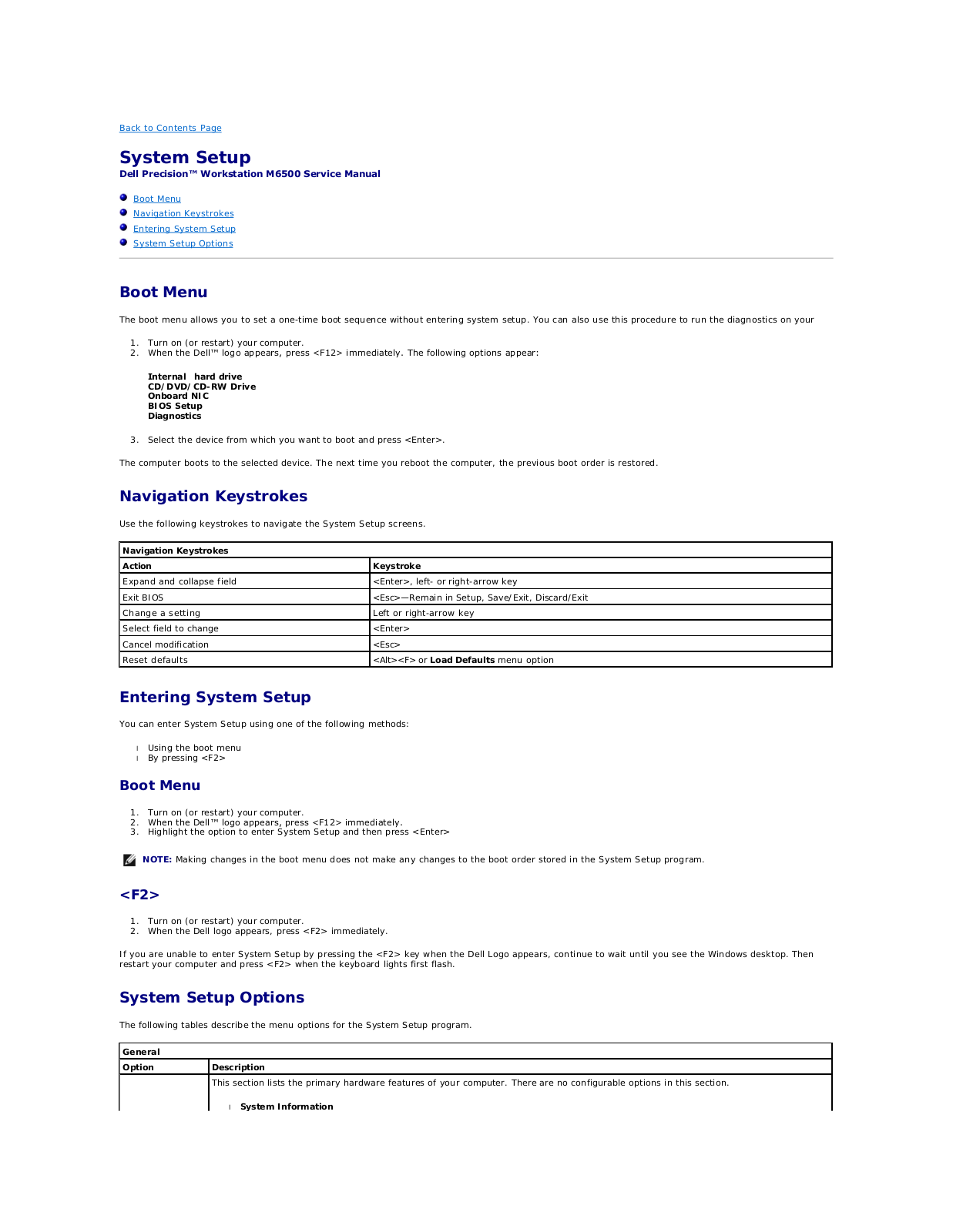
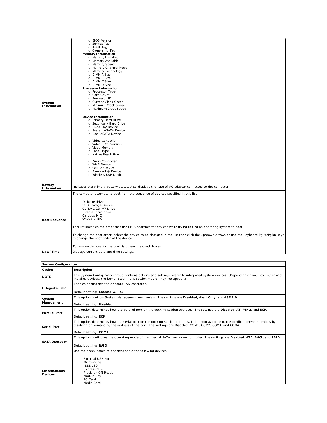
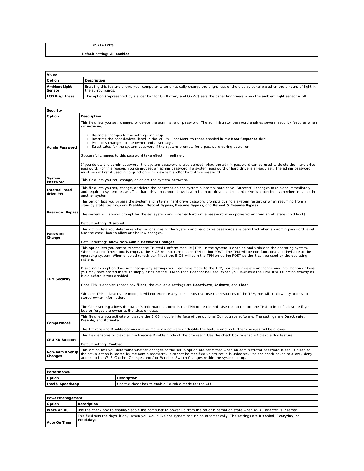
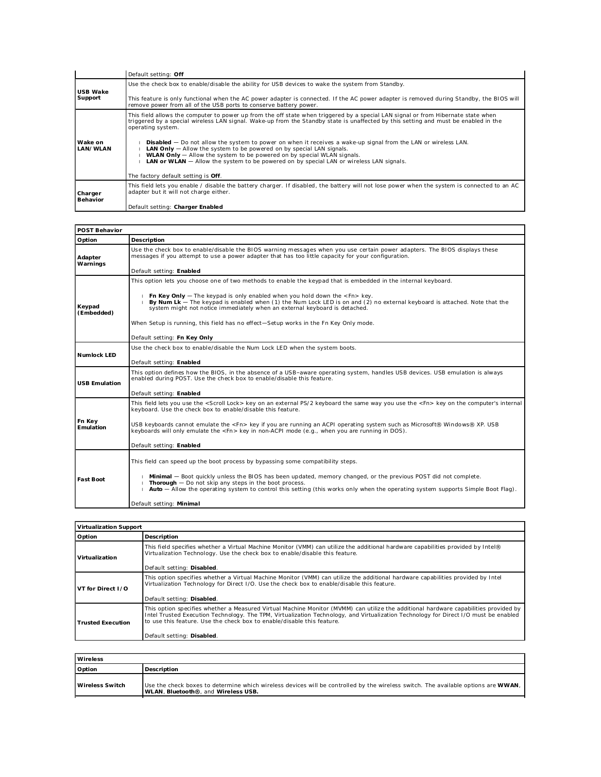
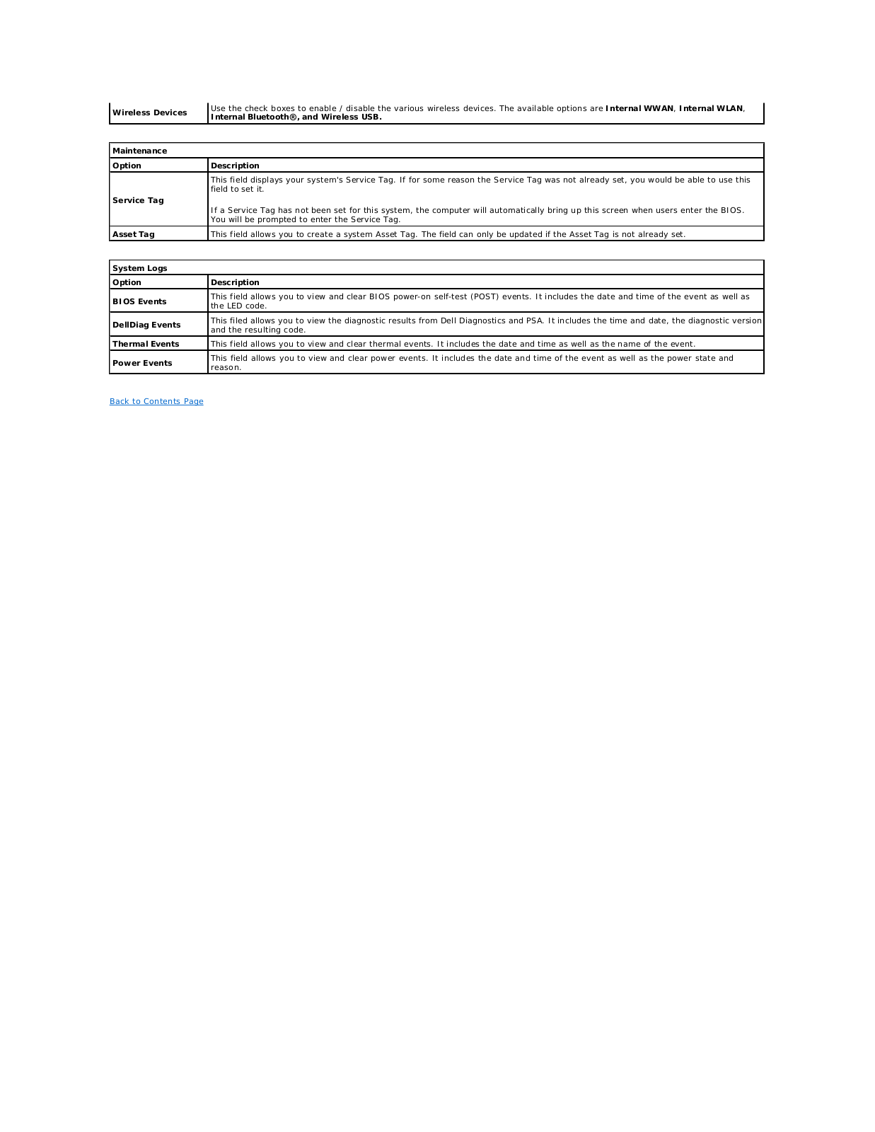
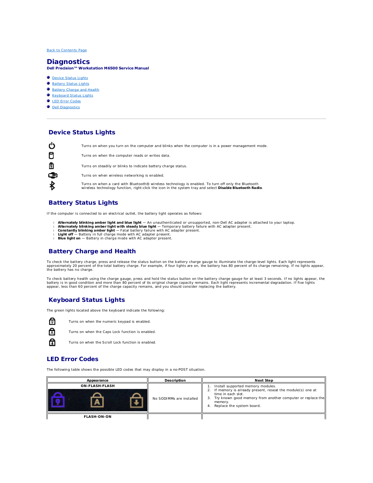
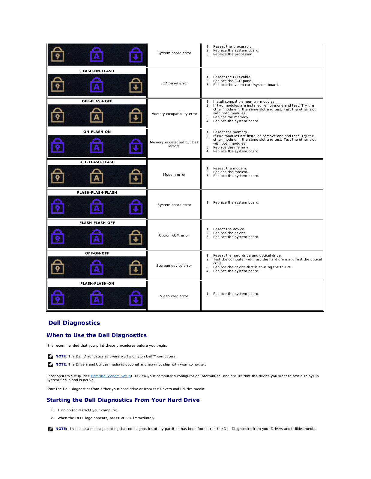
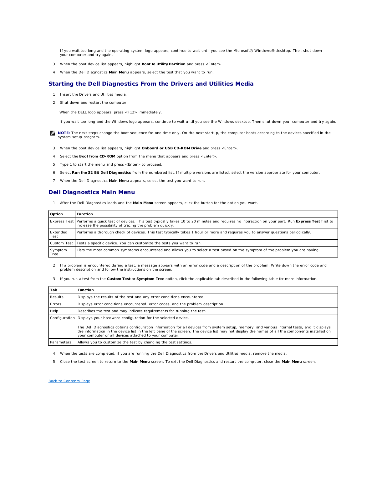
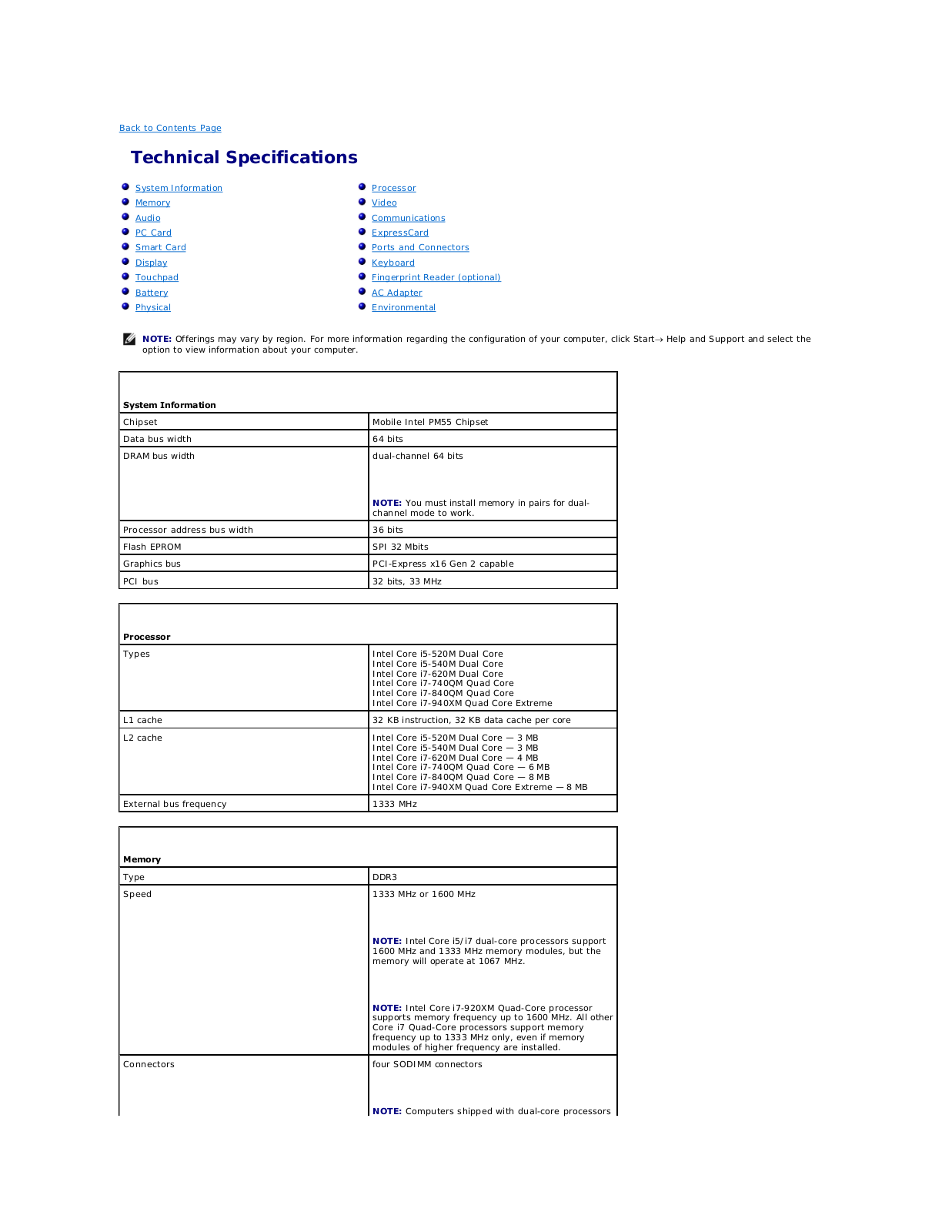
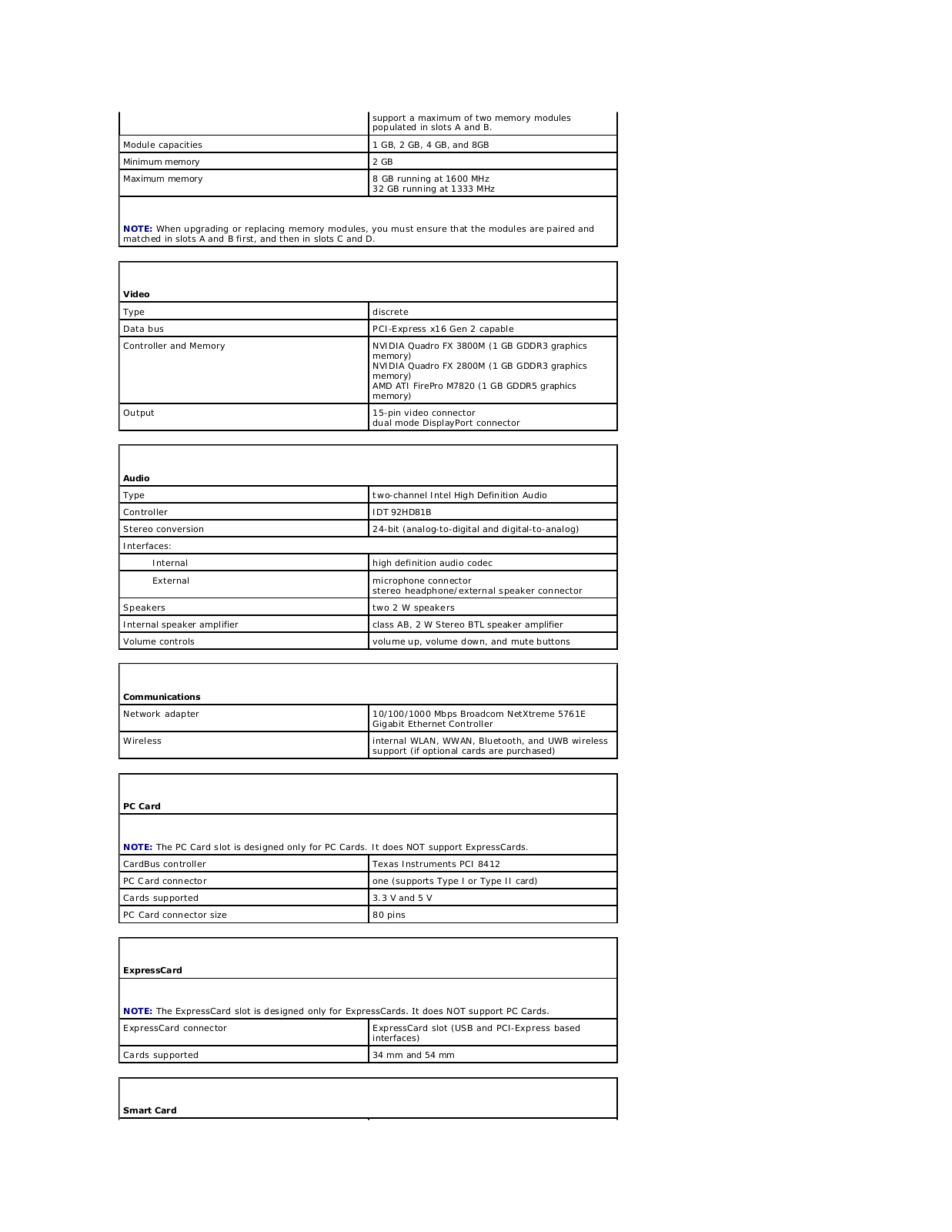
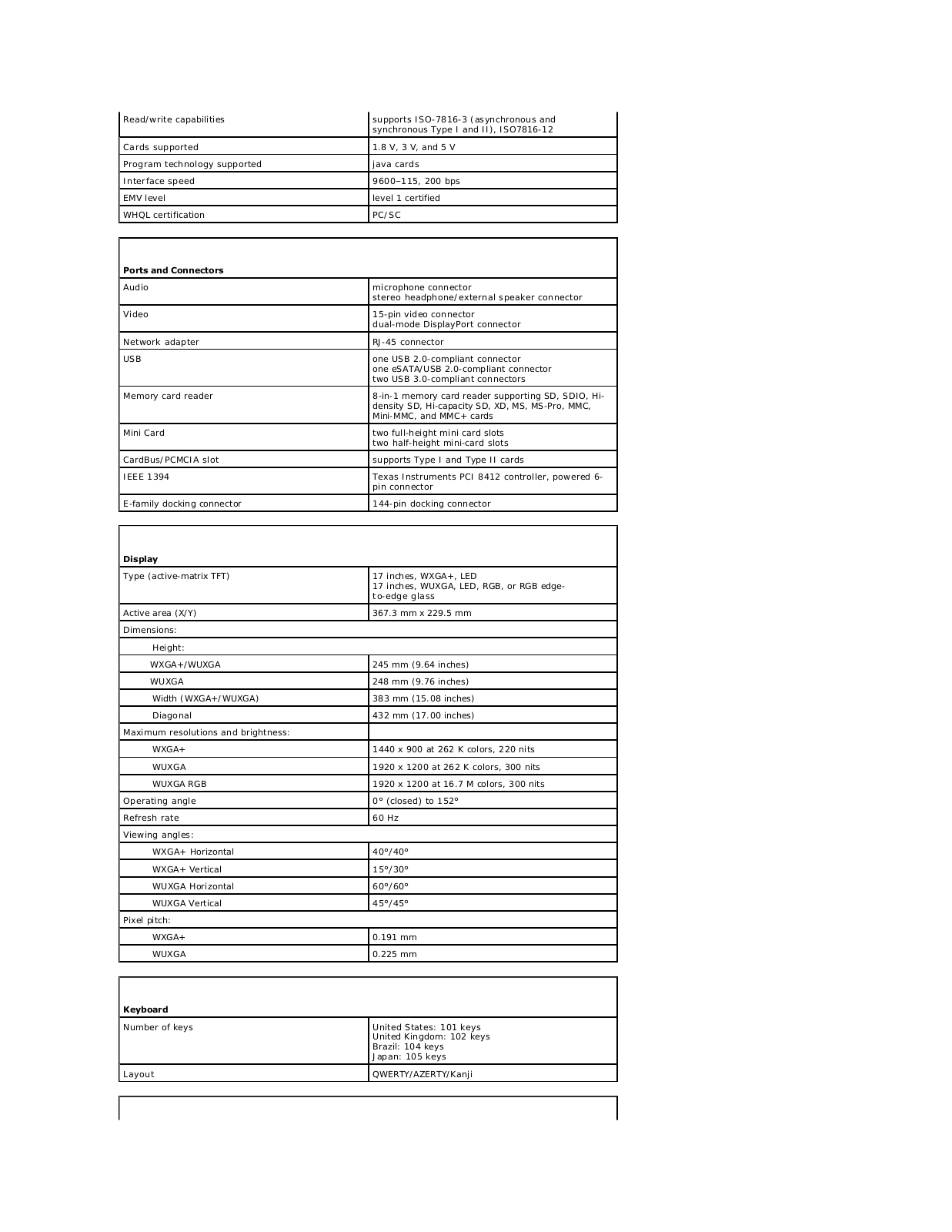
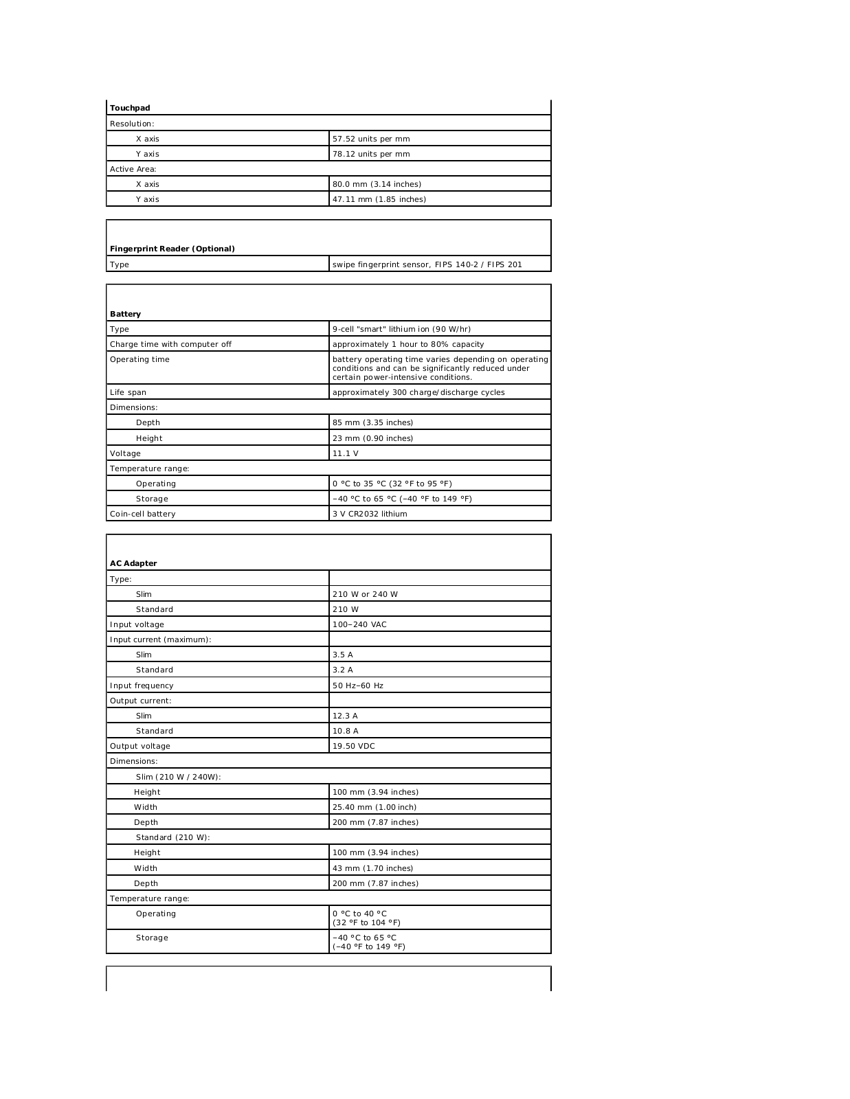
Dell Precision M6500 Service Manual
...
Dell Service Manual
Download
Specifications and Main Features
Frequently Asked Questions
User Manual
Download
Loading...
+
33
hidden pages
Unhide
You need points to download manuals.
1 point = 1 manual.
You can buy points or you can get point for every manual you upload.
Buy points
Upload your manuals
 Loading...