

Page 1

Dell Precision Mobile Workstation M4700
Owner's Manual
Regulatory Model: P21F
Regulatory Type: P21F001
Page 2

Notes, Cautions, and Warnings
NOTE: A NOTE indicates important information that helps you make better use of your computer.
CAUTION: A CAUTION indicates either potential damage to hardware or loss of data and tells you how to avoid the
problem.
NOTE: A WARNING indicates a potential for property damage, personal injury, or death.
Copyright © 2014 Dell Inc. All rights reserved. This product is protected by U.S. and international copyright and intellectual property
Dell™ and the Dell logo are trademarks of Dell Inc. in the United States and/or other jurisdictions. All other marks and names
laws.
mentioned herein may be trademarks of their respective companies.
2014 - 09
Rev. A02
Page 3

Contents
1 處理電腦.......................................................................................................................................6
Before Working Inside Your Computer............................................................................................................................... 6
Recommended Tools.............................................................................................................................................................7
Turning Off Your Computer..................................................................................................................................................7
After Working Inside Your Computer.................................................................................................................................. 7
2 卸下和安裝元件.............................................................................................................................9
Removing the Secure Digital (SD) Card.............................................................................................................................9
Installing the SD Card............................................................................................................................................................9
Removing the ExpressCard..................................................................................................................................................9
Installing the ExpressCard.................................................................................................................................................... 9
Removing the Battery...........................................................................................................................................................9
Installing the Battery............................................................................................................................................................10
Removing the Subscriber Identity Module (SIM) Card...................................................................................................10
Installing the Subscriber Identity Module (SIM) Card...................................................................................................... 11
Removing the Base Cover................................................................................................................................................... 11
Installing the Base Cover.....................................................................................................................................................12
Removing the Keyboard Trim............................................................................................................................................. 12
Installing the Keyboard Trim............................................................................................................................................... 13
Removing the Keyboard......................................................................................................................................................14
Installing the Keyboard........................................................................................................................................................ 16
Removing the Primary Memory..........................................................................................................................................17
Installing the Primary Memory............................................................................................................................................ 17
Removing the Secondary Memory.....................................................................................................................................17
Installing the Secondary Memory.......................................................................................................................................18
Removing the Optical Drive................................................................................................................................................ 18
Installing the Optical Drive.................................................................................................................................................. 19
Removing the Hard Drive....................................................................................................................................................19
Installing the Hard Drive..................................................................................................................................................... 20
Removing the Wireless Local Area Network (WLAN) Card........................................................................................... 21
Installing the Wireless Local Area Network (WLAN) Card............................................................................................. 21
Removing Wireless Wide Area Network (WWAN) Card (Optional)..............................................................................21
Installing the Wireless Wide Area Network (WWAN) Card (Optional).........................................................................22
Removing the Bluetooth Module.......................................................................................................................................22
Installing the Bluetooth Module......................................................................................................................................... 23
Removing the Processor Fan.............................................................................................................................................23
Installing the Processor Fan............................................................................................................................................... 24
Removing the Video-Card Fan.......................................................................................................................................... 24
Installing the Video-Card Fan.............................................................................................................................................24
Removing the Coin-Cell Battery........................................................................................................................................25
Installing the Coin-Cell Battery.......................................................................................................................................... 25
Removing the Palmrest...................................................................................................................................................... 25
Installing the Palmrest.........................................................................................................................................................28
Removing the ExpressCard Module..................................................................................................................................29
Contents 3
Page 4

Installing the ExpressCard Module....................................................................................................................................30
Removing The Heat Sink....................................................................................................................................................30
Installing the Heat Sink........................................................................................................................................................ 31
Removing the Processor.....................................................................................................................................................31
Installing the Processor.......................................................................................................................................................32
Removing the Video-Card Heat Sink................................................................................................................................32
Installing the Video-Card Heat Sink.................................................................................................................................. 34
Removing the Video Card.................................................................................................................................................. 34
Installing the Video Card.....................................................................................................................................................34
Removing the Input/Output (I/O) Board........................................................................................................................ 35
Installing the I/O Board.......................................................................................................................................................36
Removing the Switch Board.............................................................................................................................................. 36
Installing the Switch Board.................................................................................................................................................37
Removing the Unified Security Hub (USH) Board.......................................................................................................... 37
Installing the USH Board.....................................................................................................................................................38
Removing the Display Assembly........................................................................................................................................38
Installing the Display Assembly.......................................................................................................................................... 40
Removing the Hinge Cover.................................................................................................................................................41
Installing the Hinge Cover................................................................................................................................................... 41
Removing the System Board............................................................................................................................................. 42
Installing the System Board................................................................................................................................................44
Removing the Power-Connector Port............................................................................................................................. 45
Installing the Power-Connector Port................................................................................................................................45
Removing the Display Bezel...............................................................................................................................................46
Installing the Display Bezel..................................................................................................................................................47
Removing the Display Panel...............................................................................................................................................48
Installing the Display Panel................................................................................................................................................. 49
Removing the Camera........................................................................................................................................................50
Installing the Camera.......................................................................................................................................................... 50
3 System Setup.............................................................................................................................51
Boot Sequence (開機順序)................................................................................................................................................ 51
Navigation Keys....................................................................................................................................................................51
System Setup Options........................................................................................................................................................52
Updating the BIOS ............................................................................................................................................................. 57
系統與設定密碼..................................................................................................................................................................58
Assigning a System Password and Setup Password................................................................................................ 58
刪除或變更現有的系統及/或設定密碼.................................................................................................................... 58
4 診斷.......................................................................................................................................... 60
增強型開機前系統評估 (ePSA) 診斷..............................................................................................................................60
5 Troubleshooting Your Computer.................................................................................................. 61
Device Status Lights............................................................................................................................................................61
電池狀態指示燈...................................................................................................................................................................61
Technical Specification....................................................................................................................................................... 62
6 規格...........................................................................................................................................67
Technical Specification....................................................................................................................................................... 67
4
Contents
Page 5

7 Contacting Dell...........................................................................................................................72
聯絡 Dell................................................................................................................................................................................72
Contents 5
Page 6

處理電腦
主題:
• Before Working Inside Your Computer
• Recommended Tools
• Turning Off Your Computer
• After Working Inside Your Computer
Before Working Inside Your Computer
Use the following safety guidelines to help protect your computer from potential damage and to help to ensure your personal safety.
Unless otherwise noted, each procedure included in this document assumes that the following conditions exist:
• You have read the safety information that shipped with your computer.
• A component can be replaced or--if purchased separately--installed by performing the removal procedure in reverse order.
NOTE: Before working inside your computer, read the safety information that shipped with your computer. For
additional safety best practices information, see the Regulatory Compliance Homepage at www.dell.com/
regulatory_compliance
CAUTION: Many repairs may only be done by a certified service technician. You should only perform troubleshooting and
simple repairs as authorized in your product documentation, or as directed by the online or telephone service and
support team. Damage due to servicing that is not authorized by Dell is not covered by your warranty. Read and follow
the safety instructions that came with the product.
1
CAUTION: To avoid electrostatic discharge, ground yourself by using a wrist grounding strap or by periodically touching
an unpainted metal surface, such as a connector on the back of the computer.
CAUTION: Handle components and cards with care. Do not touch the components or contacts on a card. Hold a card by
its edges or by its metal mounting bracket. Hold a component such as a processor by its edges, not by its pins.
CAUTION: When you disconnect a cable, pull on its connector or on its pull-tab, not on the cable itself. Some cables
have connectors with locking tabs; if you are disconnecting this type of cable, press in on the locking tabs before you
disconnect the cable. As you pull connectors apart, keep them evenly aligned to avoid bending any connector pins. Also,
before you connect a cable, ensure that both connectors are correctly oriented and aligned.
NOTE: The color of your computer and certain components may appear differently than shown in this document.
To avoid damaging your computer, perform the following steps before you begin working inside the computer.
1. Ensure that your work surface is flat and clean to prevent the computer cover from being scratched.
2. Turn off your computer (see Turning Off Your Computer).
3. If the computer is connected to a docking device (docked) such as the optional Media Base or Battery Slice, undock it.
CAUTION:
the network device.
4. Disconnect all network cables from the computer.
5. Disconnect your computer and all attached devices from their electrical outlets.
6. Close the display and turn the computer upside-down on a flat work surface.
NOTE:
To disconnect a network cable, first unplug the cable from your computer and then unplug the cable from
To avoid damaging the system board, you must remove the main battery before you service the computer.
7. Remove the main battery.
8. Turn the computer top-side up.
9. Open the display.
6 處理電腦
Page 7
10. Press the power button to ground the system board.
CAUTION: To guard against electrical shock, always unplug your computer from the electrical outlet before opening
the display.
CAUTION: Before touching anything inside your computer, ground yourself by touching an unpainted metal surface,
such as the metal at the back of the computer. While you work, periodically touch an unpainted metal surface to
dissipate static electricity, which could harm internal components.
11. Remove any installed ExpressCards or Smart Cards from the appropriate slots.
Recommended Tools
The procedures in this document may require the following tools:
• Small flat-blade screwdriver
• #0 Phillips screwdriver
• #1 Phillips screwdriver
• Small plastic scribe
Turning Off Your Computer
CAUTION: To avoid losing data, save and close all open files and exit all open programs before you turn off your
computer.
1. Shut down the operating system:
• In Windows 8:
• Using a touch-enabled device:
a. Swipe in from the right edge of the screen, opening the Charms menu and select Settings.
b. Select the and then select Shut down
• Using a mouse:
a. Point to upper-right corner of the screen and click Settings.
b. Click the and select Shut down.
• In Windows 7:
a. Click Start .
b. Click Shut Down.
or
a. Click Start .
b. Click the arrow in the lower-right corner of the Start menu as shown below, and then click Shut Down..
2. Ensure that the computer and all attached devices are turned off. If your computer and attached devices did not automatically turn off
when you shut down your operating system, press and hold the power button for about 4 seconds to turn them off.
After Working Inside Your Computer
After you complete any replacement procedure, ensure you connect any external devices, cards, and cables before turning on your
computer.
CAUTION:
batteries designed for other Dell computers.
1. Connect any external devices, such as a port replicator, battery slice, or media base, and replace any cards, such as an ExpressCard.
2. Connect any telephone or network cables to your computer.
To avoid damage to the computer, use only the battery designed for this particular Dell computer. Do not use
處理電腦
7
Page 8

CAUTION: To connect a network cable, first plug the cable into the network device and then plug it into the
computer.
3. Replace the battery.
4. Connect your computer and all attached devices to their electrical outlets.
5. Turn on your computer.
8 處理電腦
Page 9
卸下和安裝元件
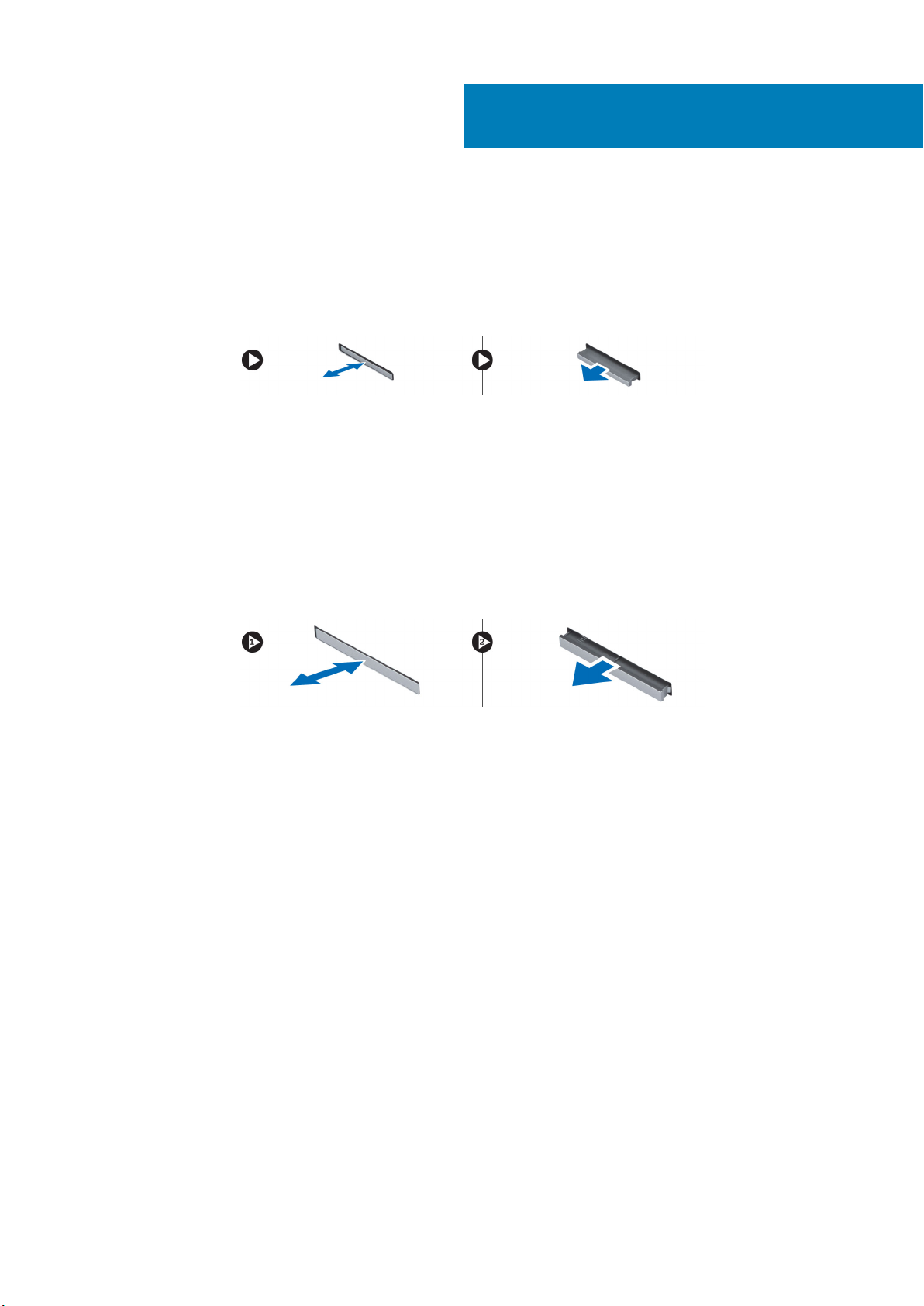
Removing the Secure Digital (SD) Card
1. Follow the procedures in Before Working Inside Your Computer.
2. Press in on the SD card to release it from the computer. Slide the SD card out of the computer.
Installing the SD Card
1. Push in the SD card into its slot until it clicks into place.
2. Follow the procedures in After Working Inside Your Computer.
Removing the ExpressCard
1. Follow the procedures in Before Working Inside Your Computer.
2. Press in on the ExpressCard to release it from the computer. Slide the ExpressCard out of the computer.
2
Installing the ExpressCard
1. Slide the ExpressCard into its slot until it clicks into place.
2. Follow the procedures in After Working Inside Your Computer.
Removing the Battery
1. Follow the procedures in Before Working Inside Your Computer.
2. Slide the release latch to unlock the battery.
卸下和安裝元件 9
Page 10
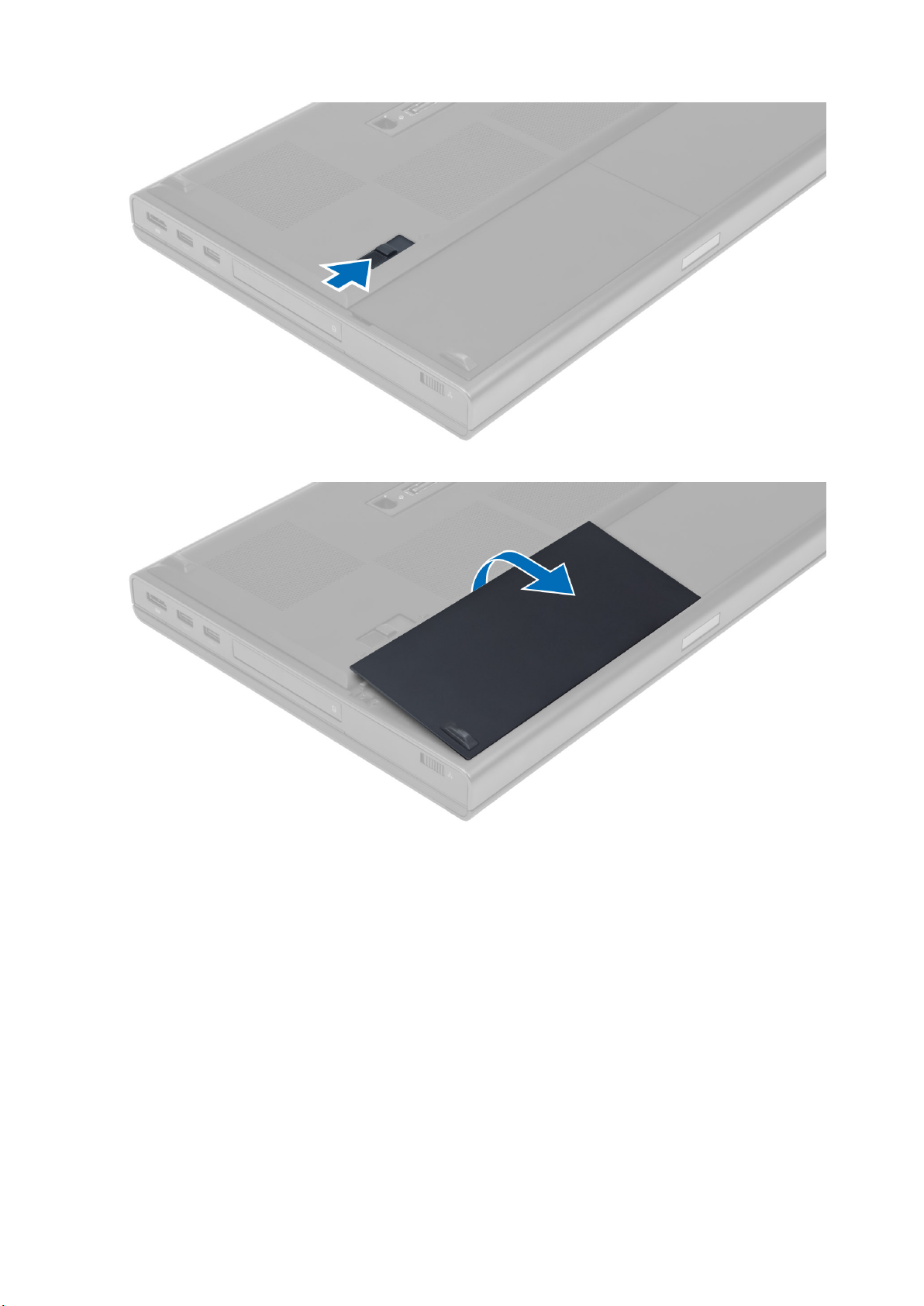
3. Flip and remove the battery from the computer.
Installing the Battery
1. Slide the battery into its slot until it clicks into place.
2. Follow the procedures in After Working Inside Your Computer.
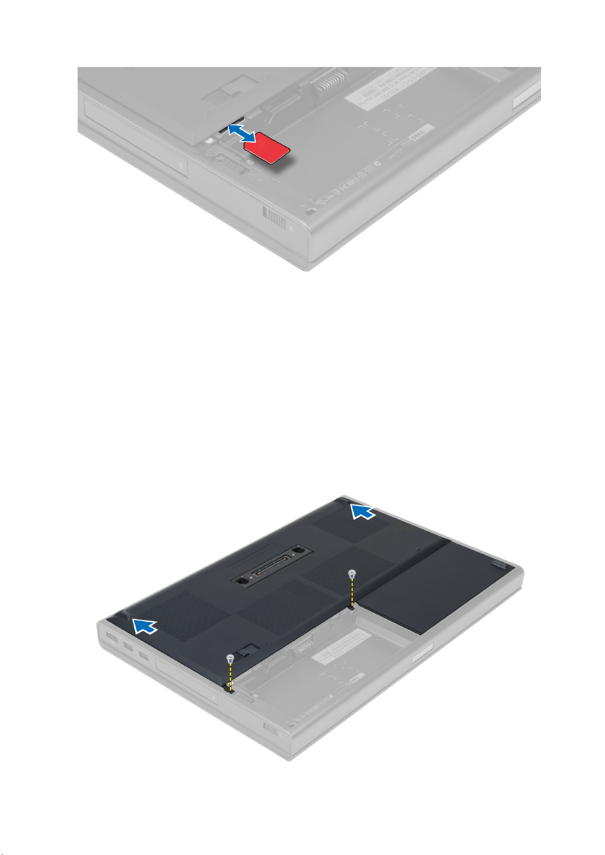
Removing the Subscriber Identity Module (SIM) Card
1. Follow the procedures in Before Working Inside Your Computer.
2. Remove the battery.
3. Slide the SIM card out from the slot .
10
卸下和安裝元件
Page 11
Installing the Subscriber Identity Module (SIM) Card
1. Push in the SIM card into its slot.
2. Install the battery.
3. Follow the procedures in After Working Inside Your Computer.
Removing the Base Cover
1. Follow the procedures in Before Working Inside Your Computer.
2. Remove the battery.
3. Remove the screws that secure the base cover to the computer. Press the rubber tabs towards the rear of the computer to
disengage the base cover.
卸下和安裝元件
11
Page 12
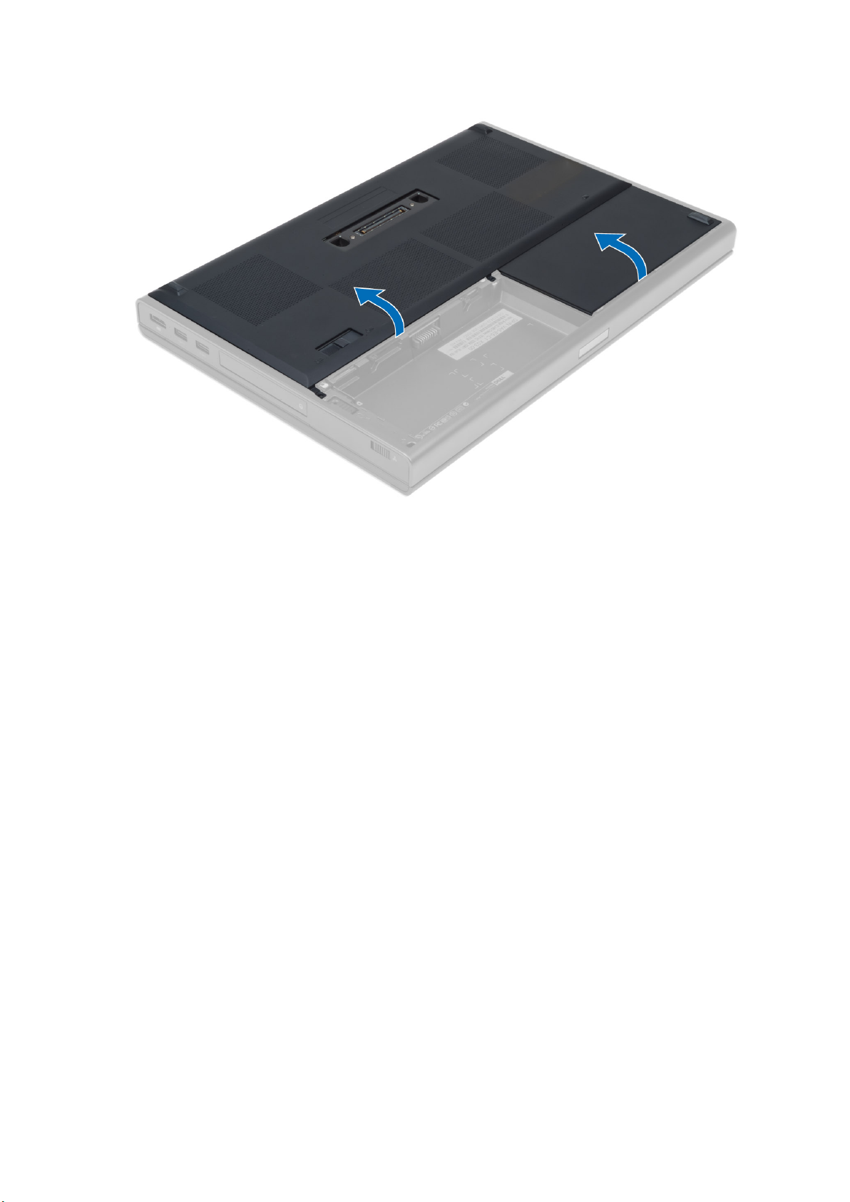
4. Flip and remove the base cover from the computer.
Installing the Base Cover
1. Slide in and place the base cover to align with the screw holes correctly on the computer.
2. Tighten the screws to secure the base cover to the computer.
3. Install the battery.
4. Follow the procedures in After Working Inside Your Computer.
Removing the Keyboard Trim
1. Follow the procedures in Before Working Inside Your Computer.
2. Remove the battery.
3. Pry up the keyboard trim starting from the top-inner edge.
12
卸下和安裝元件
Page 13
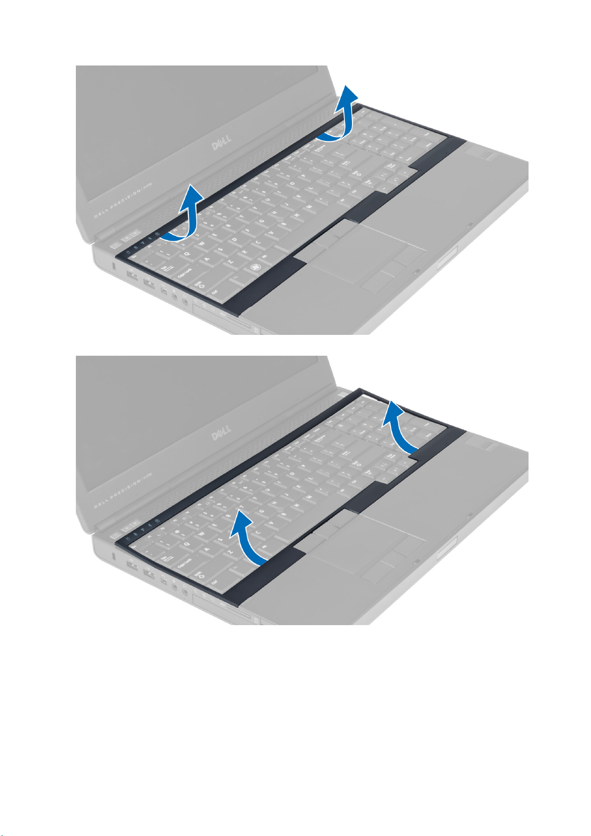
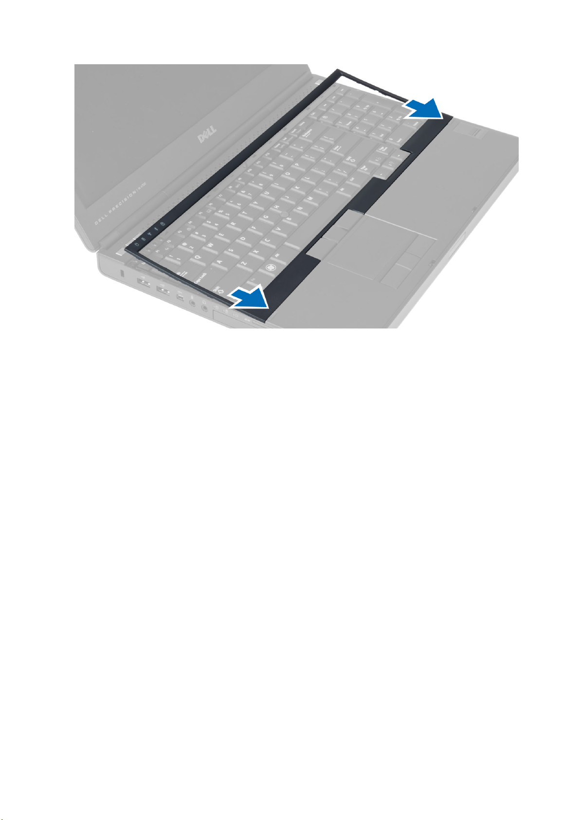
4. Pry up the bottom edge of the keyboard trim from the top-inner edge.
Installing the Keyboard Trim
1. Toe-in the keyboard trim from the front and align it to its original position on the computer. Ensure that the hard-tab on the left corner
snaps into place.
卸下和安裝元件
13
Page 14
2. Press along the sides of the keyboard trim until it snaps in place.
3. Install the battery.
4. Follow the procedures in After Working Inside Your Computer.
Removing the Keyboard
1. Follow the procedures in Before Working Inside Your Computer.
2. Remove the:
a) battery
b) keyboard trim
3. Remove the screws that secure the keyboard to the computer.
14
卸下和安裝元件
Page 15
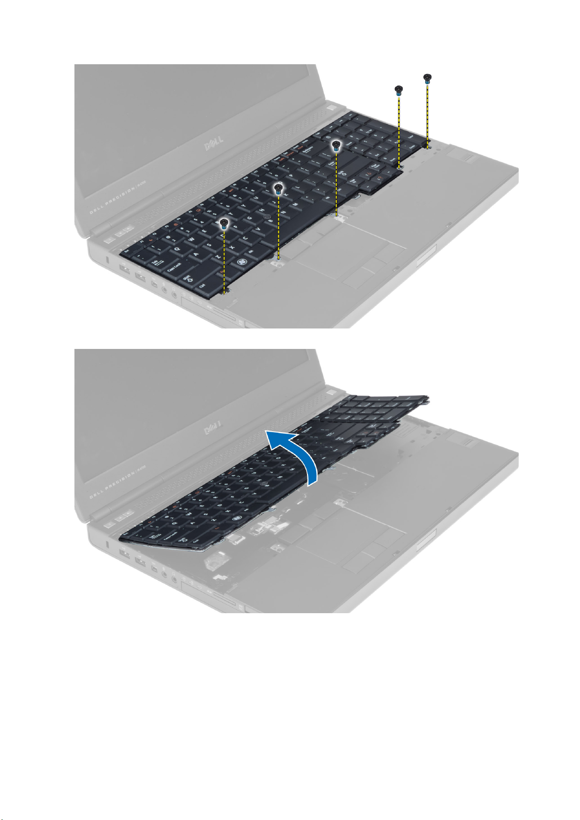
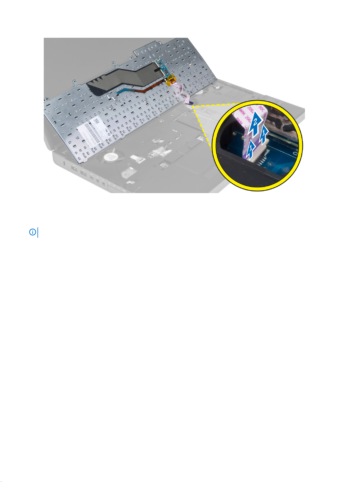
4. Starting from the bottom of the keyboard, separate the keyboard from the computer and flip the keyboard over.
5. Disconnect the keyboard-data cable from the system board and remove the keyboard.
卸下和安裝元件
15
Page 16
Installing the Keyboard
1. Connect the keyboard-data cable to the system board.
NOTE:
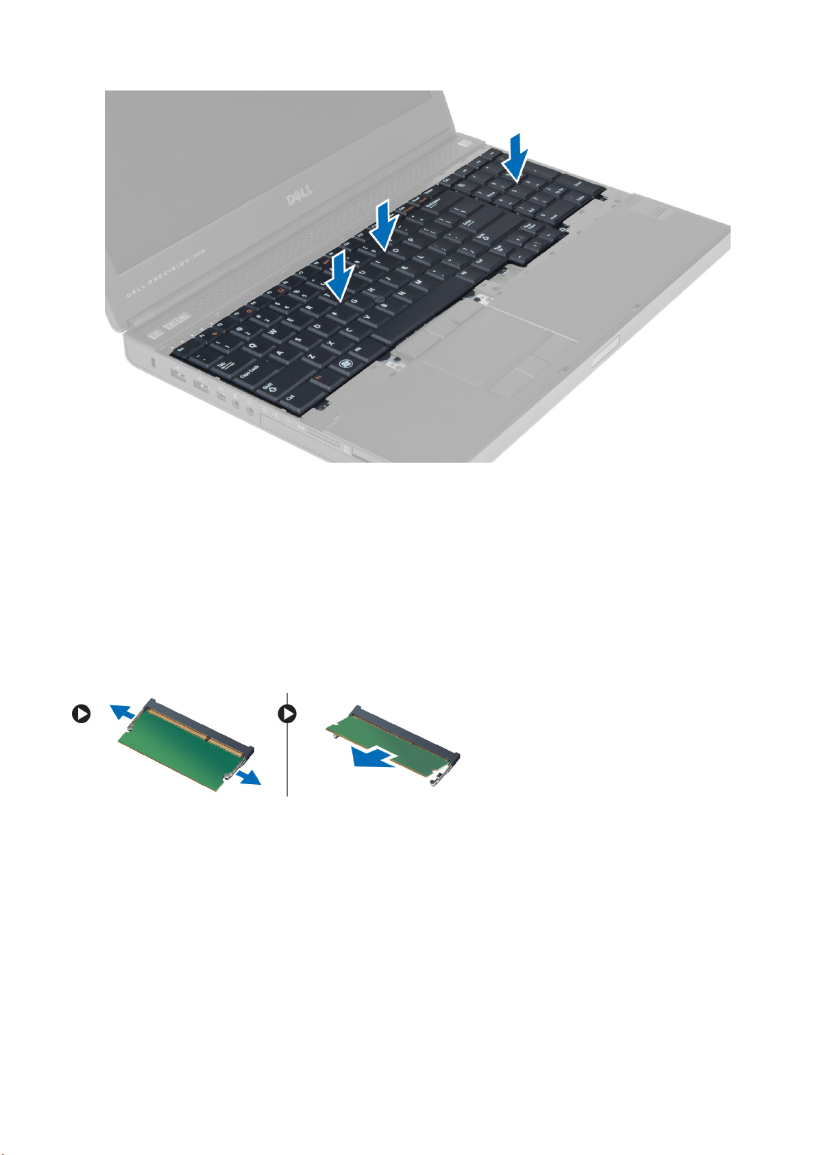
2. Press the keyboard in its compartment.
3. Tighten the screws to secure the keyboard to the computer.
4. Press over the cross section of the following keys to secure the keyboard to the computer:
a) <R> , <T> , <F> and <G> keys
b) over the <9> key
c) NUMLOCK <9> key
Ensure that you fold the keyboard-data cable in perfect alignment.
16
卸下和安裝元件
Page 17
5. Install the:
a) keyboard trim
b) battery
6. Follow the procedures in After Working Inside Your Computer.
Removing the Primary Memory
1. Follow the procedures in Before Working Inside Your Computer.
2. Remove the:
a) battery
b) base cover
3. Pry the retention clips away from the primary memory until it pops up. Lift the primary memory and remove it from the computer.
Installing the Primary Memory
1. Insert the primary memory into the memory socket.
2. Press the clips to secure the primary memory to the system board.
3. Install the:
a) base cover
b) battery
4. Follow the procedures in After Working Inside Your Computer.
Removing the Secondary Memory
1. Follow the procedures in Before Working Inside Your Computer.
卸下和安裝元件
17
Page 18
2. Remove the:
a) battery
b) keyboard trim
c) keyboard
NOTE: The secondary memory is located below the keyboard.
3. Pry the retention clips away from the memory module until it pops up. Lift up the memory module and remove it from the computer.
Installing the Secondary Memory
1. Insert the secondary memory into the memory socket.
2. Press the clips to secure the memory module to the system board.
3. Install the:
a) keyboard
b) keyboard trim
c) battery
4. Follow the procedures in After Working Inside Your Computer.
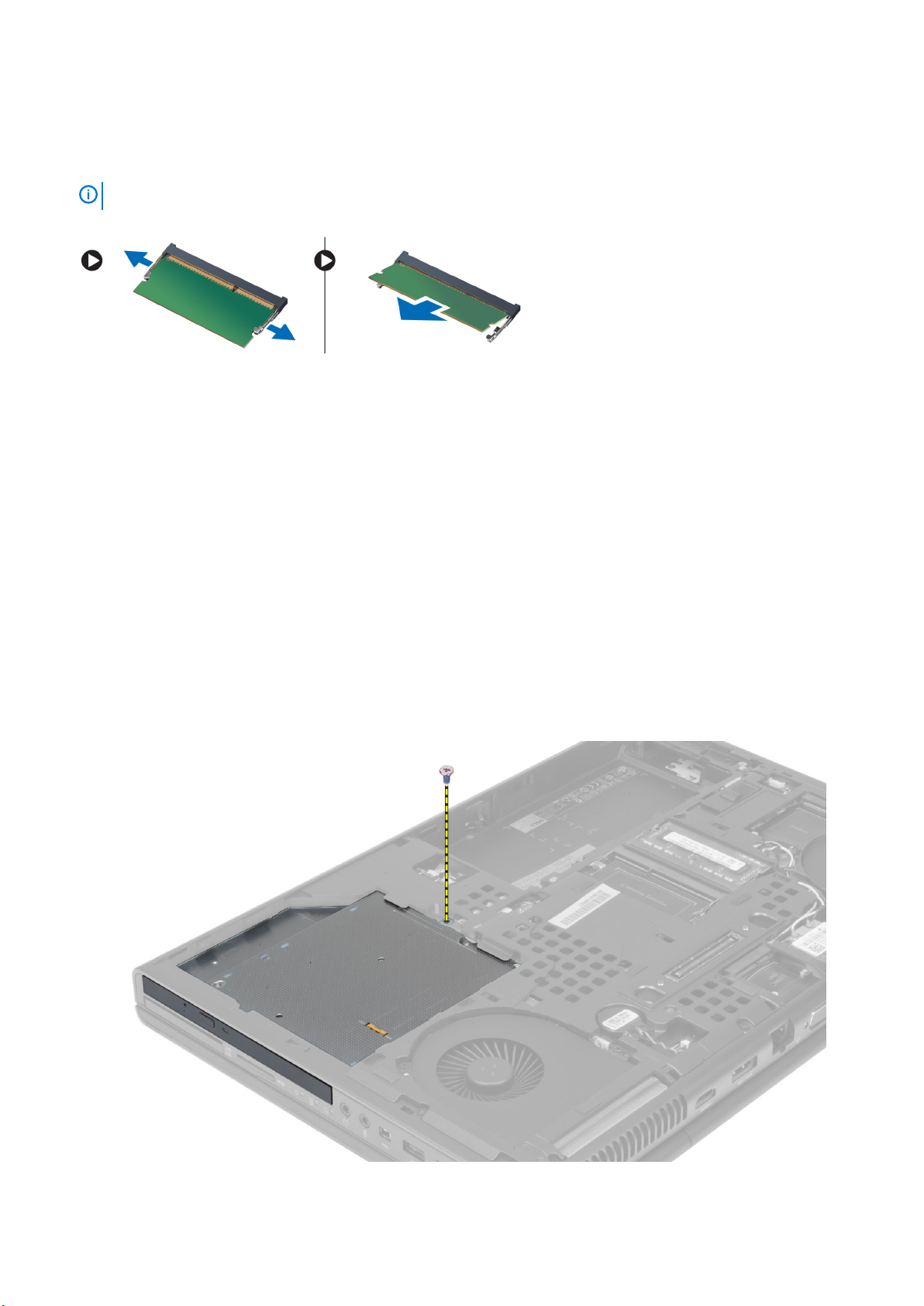
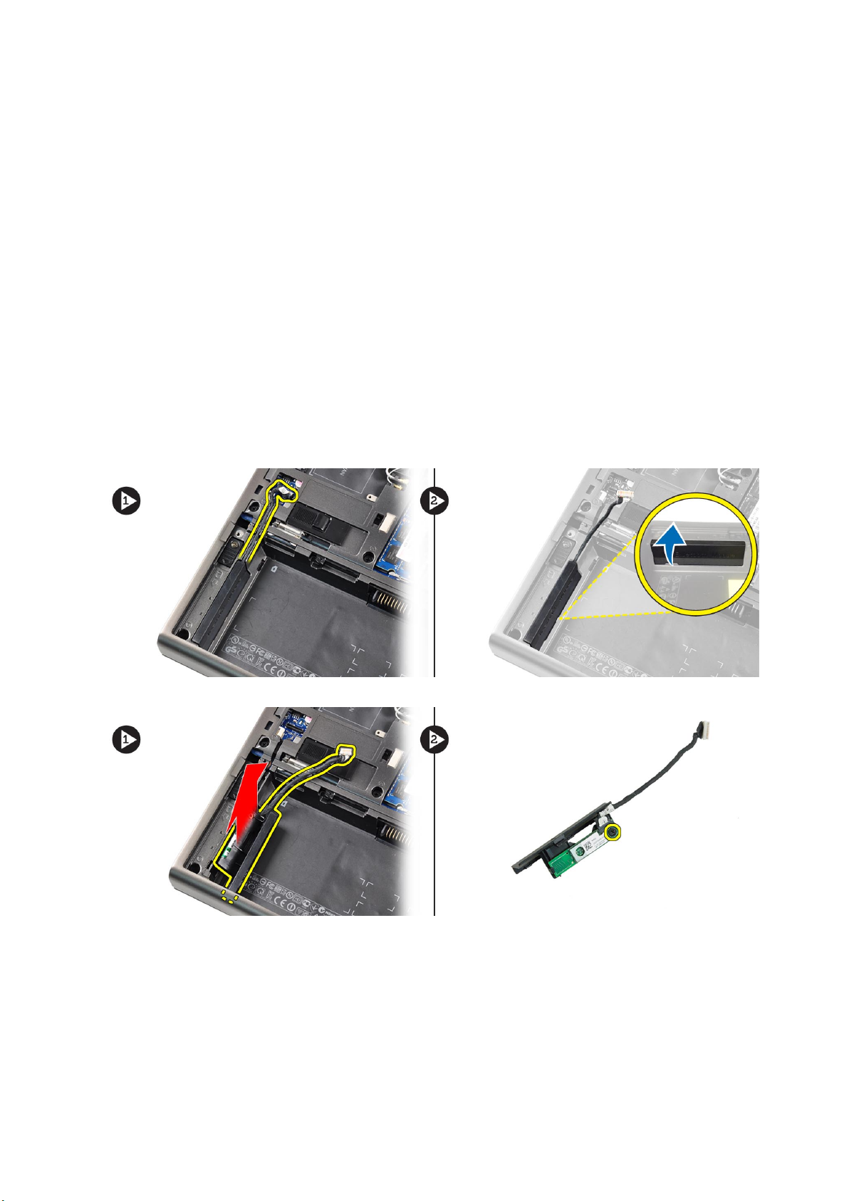
Removing the Optical Drive
1. Follow the procedures in Before Working Inside Your Computer.
2. Remove the:
a) battery
b) base cover
3. Remove the screw that secures the optical drive to the computer.
4. Pry and slide out the optical drive to remove it from the computer.
18
卸下和安裝元件
Page 19
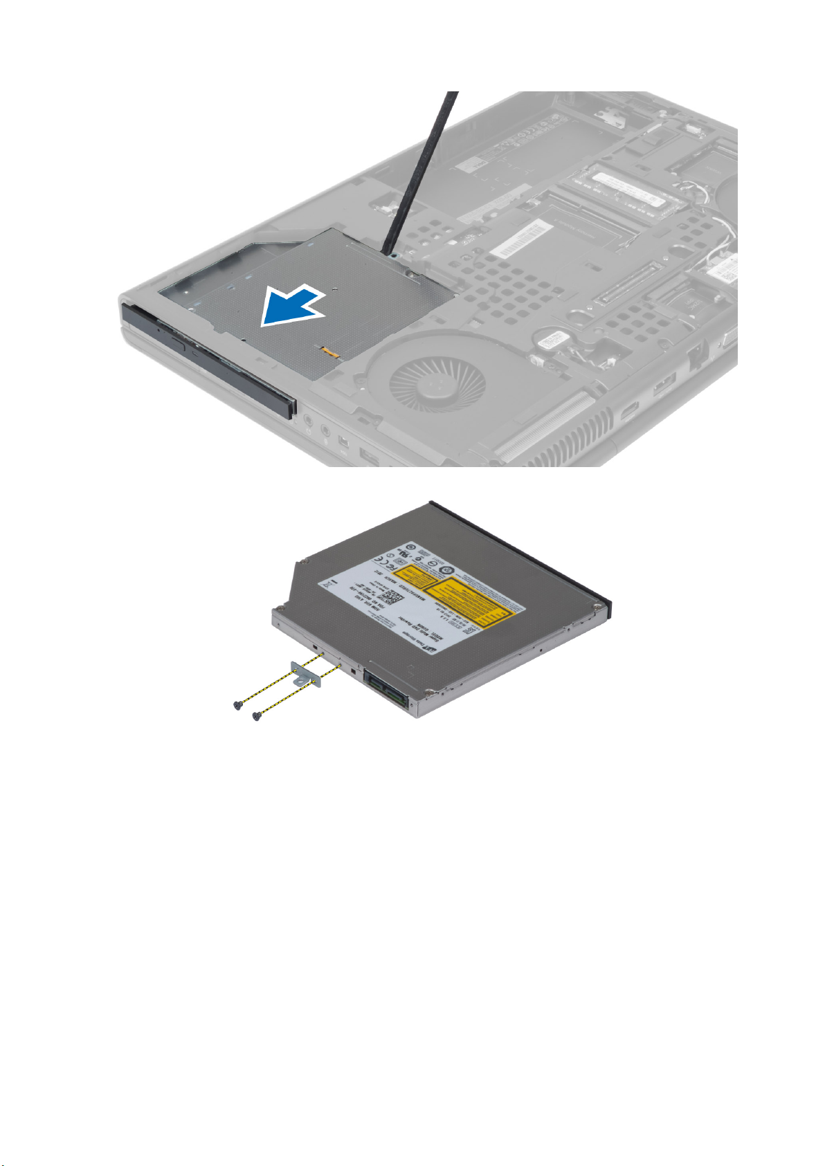
5. Remove the screws that secure the drive-latch bracket to the optical drive and remove the bracket.
Installing the Optical Drive
1. Tighten the screws to secure the drive-latch bracket to the optical drive.
2. Slide the optical drive into its slot and tighten the screw to secure the optical drive to the computer.
3. Install the:
a) battery
b) base cover
4. Follow the procedures in After Working Inside Your Computer.
Removing the Hard Drive
1. Follow the procedures in Before Working Inside Your Computer.
2. Remove the:
a) battery
b) base cover
卸下和安裝元件
19
Page 20
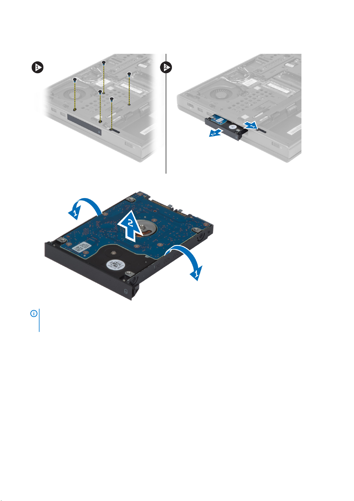
3. Remove the screws that secure the hard drive to the computer. Slide the hard -drive latch to the unlock position and pull out the hard
drive from the computer.
4. Flex the hard-drive bracket outward and pull out the hard drive from the bracket.
NOTE: A rubber filler is installed to the hard-drive bracket for 7 mm hard drives. It is designed to prevent vibrations
and for correct installation of the 7 mm hard drives. 9 mm hard drives do not require the filler when installed into the
hard-drive bracket.
Installing the Hard Drive
1. Engage the hard -drive bracket to the hard drive.
2. Insert the hard drive into its slot in the computer till it clicks in place.
3. Tighten the screws to secure the hard drive to the computer.
4. Install the:
a) base cover
b) battery
5. Follow the procedures in After Working Inside Your Computer.
20
卸下和安裝元件
Page 21
Removing the Wireless Local Area Network (WLAN) Card
1. Follow the procedures in Before Working Inside Your Computer.
2. Remove the:
a) battery
b) base cover
3. Disconnect and un-route the antenna cables connected to the WLAN card. Remove the screw that secures the WLAN card to the
computer. Remove the WLAN card from the computer.
Installing the Wireless Local Area Network (WLAN) Card
1. Insert the WLAN card in its slot in the computer.
2. Tighten the screw to secure the WLAN card to the computer.
3. Route through the routing channel and connect them to the WLAN card.
4. Install the:
a) base cover
b) battery
5. Follow the procedures in After Working Inside Your Computer.
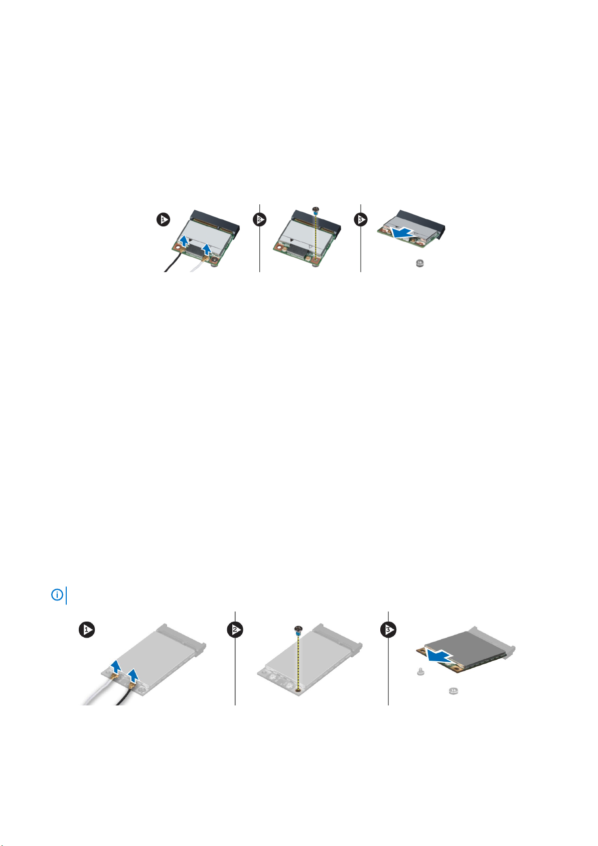
Removing Wireless Wide Area Network (WWAN) Card (Optional)
1. Follow the procedures in Before Working Inside Your Computer.
2. Remove the:
a) battery
b) base cover
3. Disconnect and un-route and remove the antenna cables connected to the WWAN card. Remove the screw that secures the WWAN
card to the computer. Remove the WWAN card from the computer.
NOTE:
The location of the WWAN card may vary from what is displayed in the illustrations.
卸下和安裝元件 21
Page 22
Installing the Wireless Wide Area Network (WWAN) Card (Optional)
1. Slide the WWAN card in the WWAN card slot.
2. Tighten the screw to secure the WWAN card to the computer.
3. Route the cables through the routing channels and connect them to the WWAN card.
4. Install the:
a) base cover
b) battery
5. Follow the procedures in After Working Inside Your Computer.
Removing the Bluetooth Module
1. Follow the procedures in Before Working Inside Your Computer.
2. Remove the:
a) battery
b) base cover
3. Disconnect and un-route the bluetooth cable. Slide the bluetooth door upward to release it.
4. Remove the bluetooth module from the computer. Remove the screw that secures the bluetooth module in place.
5. Remove the bluetooth module. Disconnect and remove the bluetooth cable from the module.
22
卸下和安裝元件
Page 23

Installing the Bluetooth Module
1. Connect the bluetooth cable to the bluetooth module.
2. Tighten the screw to secure the bluetooth module in place.
3. Insert the bluetooth module in its slot and press down the bluetooth door.
4. Route and connect the bluetooth cable.
5. Install the:
a) base cover
b) battery
6. Follow the procedures in After Working Inside Your Computer.
Removing the Processor Fan
1. Follow the procedures in Before Working Inside Your Computer.
2. Remove the:
a) battery
b) base cover
3. Remove the screws that secure the processor fan to the computer. Remove the processor fan from the computer.
4. Disconnect the processor-fan cable.
卸下和安裝元件
23
Page 24

Installing the Processor Fan
1. Connect the processor-fan cable.
2. Insert the processor fan into its slot in the computer.
3. Tighten the screws that secure the processor fan to the computer.
4. Install the:
a) base cover
b) battery
5. Follow the procedures in After Working Inside Your Computer.
Removing the Video-Card Fan
1. Follow the procedures in Before Working Inside Your Computer.
2. Remove the:
a) battery
b) base cover
3. Remove the screws that secure the video-card fan to the computer. Remove the video-card fan from the computer. Disconnect the
video-card fan cable.
Installing the Video-Card Fan
1. Connect the video-card fan cable.
2. Insert the video-card fan into its slot and tighten the screws to secure it to the computer.
3. Install the:
a) base cover
b) battery
24
卸下和安裝元件
Page 25

4. Follow the procedures in After Working Inside Your Computer.
Removing the Coin-Cell Battery
1. Follow the procedures in Before Working Inside Your Computer.
2. Remove the:
a) battery
b) base cover
3. Disconnect the coin-cell battery cable. Pry the coin-cell battery upward and remove it from the computer.
Installing the Coin-Cell Battery
1. Replace the coin-cell battery in its slot in the computer.
2. Connect the coin-cell battery cable.
3. Install the:
a) base cover
b) battery
4. Follow the procedures in After Working Inside Your Computer.
Removing the Palmrest
1. Follow the procedures in Before Working Inside Your Computer.
2. Remove the:
a) battery
b) base cover
c) keyboard trim
d) keyboard
e) optical drive
f) hard drive drive
3. Disconnect the RFID and fingerprint reader cables
卸下和安裝元件
25
Page 26

4. Remove the screws that secure the palmrest to the base of the computer.
5. Flip the computer and disconnect the following cables from the system board:
a) media board
b) speaker
c) touchpad
d) power button
26
卸下和安裝元件
Page 27

6. Remove the screws that secure the palmrest to the computer and flip it over from the edge.
7. Flip and remove the palmrest from the computer.
卸下和安裝元件
27
Page 28

Installing the Palmrest
1. Toe-in the palmrest from the front and align it to its original position on the computer.
2. Press on the positions indicated until it snaps in place.
28
卸下和安裝元件
Page 29

3. Connect the following cables to the system board:
a) power button
b) touchpad
c) speaker
d) media board
e) fingerprint
f) RFID
4. Tighten the screws to secure the palmrest to the front of the computer.
5. Tighten the screws to secure the palmrest to the base of the computer.
6. Install the:
a) hard drive
b) optical drive
c) keyboard
d) keyboard trim
e) base cover
f) battery
7. Follow the procedures in After Working Inside Your Computer.
Removing the ExpressCard Module
1. Follow the procedures in Before Working Inside Your Computer.
2. Remove the:
a) ExpressCard
b) battery
c) base cover
d) keyboard trim
e) keyboard
f) optical drive
g) hard drive
h) palm rest
3. Disconnect the :
a) ExpressCard cable from the system board
b) the USH board cable from the USH board (M4700 only)
卸下和安裝元件
29
Page 30

4. Remove the screws that secure the ExpressCard module to the computer and remove the ExpressCard module.
Installing the ExpressCard Module
1. Insert the ExpressCard module into its compartment.
2. Tighten the screws to secure the ExpressCard module to the computer
3. Connect the:
a) ExpressCard cable to the system board
b) the USH board cable to the USH board (for M4700 only)
4. Install the:
a) palm rest
b) hard drive
c) optical drive
d) keyboard
e) keyboard trim
f) base cover
g) battery
h) ExpressCard
5. Follow the procedures in After Working Inside Your Computer.
Removing The Heat Sink
1. Follow the procedures in Before Working Inside Your Computer.
2. Remove the:
a) battery
b) base cover
30
卸下和安裝元件
Page 31

c) keyboard trim
d) keyboard
e) optical drive
f) hard drive
g) palm rest
h) processor fan
3. Loosen the captive screws that secure the heat sink to the computer. Lift up and remove the heat sink from the computer.
Installing the Heat Sink
1. Replace the heat sink in its slot. Tighten the captive screws to secure the heat sink to the computer.
2. Install the:
a) processor fan
b) palm rest
c) hard drive
d) optical drive
e) keyboard
f) keyboard trim
g) base cover
h) battery
3. Follow the procedures in After Working Inside Your Computer.
Removing the Processor
1. Follow the procedures in Before Working Inside Your Computer.
2. Remove the:
a) battery
b) base cover
c) keyboard trim
d) keyboard
e) optical drive
f) hard drive
g) palm rest
h) processor fan
i) heat sink
3. Rotate the processor cam lock in a counter-clockwise direction. Remove the processor from the computer.
卸下和安裝元件
31
Page 32

Installing the Processor
1. Align the notches on the processor and the socket, and insert the processor into the socket.
2. Rotate the processor cam lock in a clockwise direction.
3. Install the:
a) heat sink
b) processor fan
c) palm rest
d) hard drive
e) optical drive
f) keyboard
g) keyboard trim
h) base cover
i) battery
4. Follow the procedures in After Working Inside Your Computer.
Removing the Video-Card Heat Sink
1. Follow the procedures in Before Working Inside Your Computer.
2. Remove the:
a) battery
b) bottom door
c) keyboard trim
d) keyboard
e) optical drive
f) hard drive
g) palm rest
h) video fan
3. Disconnect and un-route any antenna cables connected to installed wireless cards.
32
卸下和安裝元件
Page 33

4. Remove the antenna cables from the routing channels.
5. Loosen the captive screws on the heat sink.
6. Remove the video-card heat sink from the computer.
卸下和安裝元件
33
Page 34

Installing the Video-Card Heat Sink
1. Slide the heat sink into its original position in the computer.
2. Tighten the captive screws to secure the heat sink.
3. Route and connect the antenna cables to the installed wireless cards.
4. Install the:
a) video fan
b) palm rest
c) hard drive
d) optical drive
e) keyboard
f) keyboard trim
g) bottom door
h) battery
5. Follow the procedures in After Working Inside Your Computer.
Removing the Video Card
1. Follow the procedures in Before Working Inside Your Computer.
2. Remove the:
a) battery
b) base cover
c) keyboard trim
d) keyboard
e) optical drive
f) hard drive
g) palm rest
h) video-card fan
i) video-card heat sink
j) heatsink
3. Remove the screws that secure the video card to the computer. Remove the video card from the computer.
Installing the Video Card
1. Insert the video card into its slot in the computer.
2. Tighten the screws to secure it to the computer.
3. Install the:
a) heatsink
b) video-card heat sink
c) video-card fan
d) palm rest
e) hard drive
34
卸下和安裝元件
Page 35

f) optical drive
g) keyboard
h) keyboard trim
i) base cover
j) battery
4. Follow the procedures in After Working Inside Your Computer.
Removing the Input/Output (I/O) Board
1. Follow the procedures in Before Working Inside Your Computer.
2. Remove the:
a) SD card
b) battery
c) base cover
d) keyboard trim
e) keyboard
f) optical drive
g) hard drive
h) palmrest
3. Disconnect the ExpressCard module connector from the I/O board.
4. Remove the screw that secures the I/O board to the computer. Lift the right edge of the I/O board upwards to disengage the
connector and remove it from computer.
卸下和安裝元件
35
Page 36

Installing the I/O Board
1. Connect the I/O board connector and slide the I/O board into its slot in the computer.
2. Tighten the screw to secure the I/O board to the computer.
3. Connect the ExpressCard module connector to the I/O board.
4. Install the:
a) palmrest
b) hard drive
c) optical drive
d) keyboard
e) keyboard trim
f) base cover
g) battery
h) SD card
5. Follow the procedures in After Working Inside Your Computer.
Removing the Switch Board
1. Follow the procedures in Before Working Inside Your Computer.
2. Remove the:
a) battery
b) base cover
c) keyboard trim
d) keyboard
e) optical drive
f) hard drive
g) palmrest
3. Disconnect the switch-board cable from the system board and remove it from the latches. Remove the screws that secure the switch
board to the computer and remove it from the computer.
36
卸下和安裝元件
Page 37

Installing the Switch Board
1. Align the switch board to its original position on the computer.
2. Tighten the screws to secure the switch board to the computer.
3. Connect the switch-board cable to the system board and secure it through the routing channel.
4. Install the:
a) palmrest
b) hard drive
c) optical drive
d) keyboard
e) keyboard trim
f) base cover
g) battery
5. Follow the procedures in After Working Inside Your Computer.
Removing the Unified Security Hub (USH) Board
1. Follow the procedures in Before Working Inside Your Computer.
2. Remove the:
a) battery
b) base cover
c) keyboard trim
d) keyboard
e) optical drive
f) hard drive
g) palmrest
3. Disconnect the smart-card and the USH cable from the system board. Remove the screws that secure the USH board to the
computer and remove it from the computer.
卸下和安裝元件
37
Page 38

Installing the USH Board
1. Align the USH board to its original position on the computer.
2. Tighten the screws to secure the USH board to the computer.
3. Connect the smart-card and the USH board cables to the system board.
4. Install the:
a) palmrest
b) hard drive
c) optical drive
d) keyboard
e) keyboard trim
f) base cover
g) battery
5. Follow the procedures in After Working Inside Your Computer.
Removing the Display Assembly
1. Follow the procedures in Before Working Inside Your Computer.
2. Remove the:
a) battery
b) base cover
c) keyboard trim
d) keyboard
e) optical drive
f) hard drive
g) palmrest
3. Disconnect the antenna cables from the wireless cards, and push them down the routing hole.
4. Flip the computer and pull up the antenna cables through the routing hole.
38
卸下和安裝元件
Page 39

5. Flip the computer and remove the screws from the bottom and back of the computer.
6. Remove the screws that secure the low-voltage differential signalling (LVDS) cable bracket. Remove the LVDS cable bracket and
disconnect the LVDS cable and camera cable from the system board.
NOTE:
LVDS cable is available in M4700 without the bracket. LVDS cable bracket is available only in M6700.
卸下和安裝元件 39
Page 40

7. Remove the screws that secure the display assembly to the computer. Remove the display assembly from the computer.
Installing the Display Assembly
1. Tighten the screws to secure the display assembly in place.
2. Connect the camera and LVDS cables to the correct connectors on the system board.
3. Place the LVDS cable bracket on the computer and tighten the screws to secure it to the computer.
NOTE:
4. Route the cables through the routing channels.
5. Insert the wireless antenna cables through the routing hole on the chassis.
40
LVDS cable is available in M4700 without the bracket. LVDS cable bracket is available only in M6700.
卸下和安裝元件
Page 41

6. Tighten the screws at the bottom and back of the computer.
7. Route and connect the antenna cables to their connectors.
8. Install the:
a) palmrest
b) hard drive
c) optical drive
d) keyboard
e) keyboard trim
f) base cover
g) battery
9. Follow the procedures in After Working Inside Your Computer.
Removing the Hinge Cover
1. Follow the procedures in Before Working Inside Your Computer.
2. Remove the:
a) battery
b) base cover
c) keyboard trim
d) keyboard
e) optical drive
f) hard drive
g) palmrest
h) display assembly
3. Remove the screws that secure the hinge cover to the computer. Remove the hinge cover from the computer.
Installing the Hinge Cover
1. Place the hinge cover in its position on the computer.
2. Tighten the screws to secure the hinge cover to the computer.
3. Install the:
a) display assembly
b) palmrest
c) hard drive
d) optical drive
e) keyboard
f) keyboard trim
g) base cover
h) battery
4. Follow the procedures in After Working Inside Your Computer.
卸下和安裝元件
41
Page 42

Removing the System Board
1. Follow the procedures in Before Working Inside Your Computer.
2. Remove the:
a) SD card
b) ExpressCard
c) battery
d) base cover
e) keyboard trim
f) keyboard
g) optical drive
h) hard drive
i) primary memory
j) secondary memory
k) processor fan
l) video-card fan
m) palmrest
n) heat sink
o) processor
p) video-card heat sink
q) video card
r) I/O board
s) display assembly
3. Disconnect the coin-cell battery cable.
4. Disconnect the bluetooth cable.
5. Disconnect the USH connector cable.
42
卸下和安裝元件
Page 43

6. Disconnect the USH cable.
7. Disconnect the wireless cable.
8. Remove all mini-cards (if available).
9. Remove the screws that secure the system board in place and lift the top edge of the system board to a 20° angle.
10. Disconnect the power connector cable and remove the system board.
卸下和安裝元件
43
Page 44

Installing the System Board
1. Connect the power connector cable to the system board.
2. Place the system board in its compartment.
3. Tighten the screws to secure the system board to the computer.
4. Connect the following cables:
a) USH connector
b) bluetooth
c) wireless board connectors
d) coin-cell battery
5. Install the wireless cards (if available).
6. Install the:
a) display assembly
b) I/O board
c) video card
d) video-card heat sink
e) processor
f) heat sink
g) palmrest
h) video-card fan
i) processor fan
j) secondary memory
k) primary memory
l) hard drive
m) optical drive
n) keyboard
o) keyboard trim
p) base cover
q) battery
r) ExpressCard
s) SD card
7. Follow the procedures in After Working Inside Your Computer.
44
卸下和安裝元件
Page 45

Removing the Power-Connector Port
1. Follow the procedures in Before Working Inside Your Computer.
2. Remove the:
a) SD card
b) ExpressCard
c) battery
d) base cover
e) keyboard trim
f) keyboard
g) optical drive
h) hard drive
i) primary memory
j) secondary memory
k) processor fan
l) video-card fan
m) palm rest
n) processor heatsink
o) processor
p) video-card heatsink
q) video card
r) I/O board
s) display assembly
t) system board
3. Un-route and lift up the power-connector cable from the chassis to remove the power-connector port.
Installing the Power-Connector Port
1. Insert the power-connector port in its slot and route the power-connector cable to the chassis.
2. Install the:
a) system board
b) display assembly
c) I/O board
d) video card
e) video-card heat sink
f) processor
g) processor heatsink
h) palm rest
i) video-card fan
j) processor fan
k) secondary memory
l) primary memory
卸下和安裝元件
45
Page 46

m) hard drive
n) optical drive
o) keyboard
p) keyboard trim
q) base cover
r) battery
s) ExpressCard
t) SD card
3. Follow the procedures in After Working Inside Your Computer.
Removing the Display Bezel
1. Follow the procedures in After Working Inside Your Computer.
2. Remove the battery.
3. Pry up the bottom edge of the display bezel.
4. Work your way around the sides and top edge of the display bezel and remove the display bezel from the computer .
46
卸下和安裝元件
Page 47

Installing the Display Bezel
1. Slide in the display bezel from the bottom and press on the display bezel.
2. Work around the entire bezel until it snaps onto the display assembly.
3. Install the battery.
卸下和安裝元件
47
Page 48

4. Follow the procedures in After Working Inside Your Computer.
Removing the Display Panel
1. Follow the procedures in Before Working Inside Your Computer.
2. Remove the:
a) battery
b) display bezel
3. Remove the screw that secures the display panel to the display assembly. Flip the display panel over.
Peel back the adhesive tape that secures the LVDS cable to the display panel.
4.
5. Disconnect the LVDS cable.
48
卸下和安裝元件
Page 49

6. Remove the screws that secure the display brackets to the display panel. Remove the display brackets.
7.
Installing the Display Panel
1. Align the display brackets to the display panel.
2. Tighten the screws to secure the display brackets to the display panel.
3. Connect the LVDS cable and affix the adhesive tape.
4. Align the display panel in its original position on the computer.
5. Tighten the screws to secure the display panel to the display assembly.
卸下和安裝元件
49
Page 50

6. Install the:
a) display bezel
b) battery
7. Follow the procedures in After Working Inside Your Computer.
Removing the Camera
1. Follow the procedures in Before Working Inside Your Computer.
2. Remove the:
a) battery
b) display bezel
3. Disconnect the camera cable. Remove the screw that secures the camera module to the computer. Remove the camera module from
the computer.
Installing the Camera
1. Place the camera module in its slot on the computer.
2. Tighten the screw to secure the camera module to the computer.
3. Connect the camera cable.
4. Install the:
a) display bezel
b) battery
5. Follow the procedures in After Working Inside Your Computer.
50
卸下和安裝元件
Page 51

3
System Setup
System Setup enables you to manage your computer hardware and specify BIOS‐level options. From the System Setup, you can:
• Change the NVRAM settings after you add or remove hardware
• View the system hardware configuration
• Enable or disable integrated devices
• Set performance and power management thresholds
• Manage your computer security
Topics:
• Boot Sequence (開機順序)
• Navigation Keys
• System Setup Options
• Updating the BIOS
• 系統與設定密碼
Boot Sequence (開機順序)
Boot Sequence (開機順序) 可讓您略過系統設定定義的啟動裝置順序,並直接開機至特定裝置 (例如:光碟機或硬碟)。開機自我測試
(POST) 期間,當螢幕上出現 Dell 標誌時,您可以:
• 按下 <F2> 鍵存取系統設定
• 按下 <F12> 鍵顯示單次開機功能表
單次開機功能表會顯示可用的開機裝置,包括診斷選項。可用的開機功能表選項有:
• Removable Drive (卸除式磁碟機) (如有)
• STXXXX Drive (STXXXX 磁碟機)
XXX 代表 SATA 磁碟機編號。
備註:
• Optical Drive (光碟機)
• Diagnostics (診斷)
選擇 Diagnostics (診斷) 將會顯示 ePSA diagnostics (ePSA 診斷) 畫面。
備註:
開機順序畫面也會顯示選項,讓您存取 System Setup (系統設定) 畫面。
Navigation Keys
The following table displays the system setup navigation keys.
NOTE:
start the system.
Table 1. Navigation Keys
Keys Navigation
Up arrow Moves to the previous field.
Down arrow Moves to the next field.
<Enter> Allows you to select a value in the selected field (if applicable) or follow the link in the field.
Spacebar Expands or collapses a drop‐down list, if applicable.
<Tab> Moves to the next focus area.
For most of the system setup options, changes that you make are recorded but do not take effect until you re-
NOTE: For the standard graphics browser only.
System Setup 51
Page 52

Keys Navigation
<Esc> Moves to the previous page till you view the main screen. Pressing <Esc> in the main screen displays a
message that prompts you to save any unsaved changes and restarts the system.
<F1> Displays the System Setup help file.
System Setup Options
NOTE: Depending on your computer and installed devices, the items listed in this section may or may not appear.
Table 2. General
Option Description
System Information This section lists the primary hardware features of your computer.
• System Information
• Memory Information
• Processor Information
• Device Information
Battery Information Displays the charge status of the battery.
Boot Sequence Allows you to change the order in which the computer attempts to find an operating system. All the
options are selected.
• Diskette Drive
• Internal HDD
• USB Storage Device
• CD/DVD/CD-RW Drive
• Onboard NIC
You can also choose the Boot List option. The options are:
• Legacy (Default Setting)
• UEFI
Date/Time Allows you to set the date and time.
Table 3. System Configuration
Option Description
Integrated NIC Allows you to configure the integrated network controller. The options are:
• Disabled
• Enabled
• Enabled w/PXE (Default Setting)
Parallel Port Allows you to define and set how the parallel port on the docking station operates. You can set the
parallel port to:
• Disabled
• AT
• PS2
• ECP
Serial Port Identifies and defines the serial port settings. You can set the serial port to:
• Disabled
• COM1 (Default Setting)
• COM2
• COM3
• COM4
NOTE: The operating system may allocate resources even if the setting is disabled.
52 System Setup
Page 53

Option Description
SATA Operation Allows you to configure the internal SATA hard-drive controller. The options are:
• Disabled
• ATA
• AHCI
• RAID On (Default Setting)
NOTE: SATA is configured to support RAID mode.
Drives Allows you to configure the SATA drives on board. The options are:
• SATA-0
• SATA-1
• SATA-3
• SATA-4
• SATA-5
Default Setting: All drives are enabled.
SMART Reporting This field controls whether hard drive errors for integrated drives are reported during system
startup. This technology is part of the SMART (Self Monitoring Analysis and Reporting Technology)
specification.
• Enable SMART Reporting — This option is disabled by default.
USB Configuration Allows you to define the USB configuration. The options are:
• Enable Boot Support
• Enable External USB Port
Default Setting: both the options are enabled.
USB PowerShare Allows you to configure the behavior of the USB PowerShare feature. This option is disabled by
default.
• Enable USB PowerShare
Miscellaneous Devices Allows you enable or disable the various on board devices. The options are:
• Enable Fixed Bay
• Enable Microphone
• Enable ExpressCard
• Enable eSATA Ports
• Enable Camera
• Enable Hard Drive Free Fall Protection
• Enable Media Card and 1394
• Enable Media Card Only
• Disable MC, 1394
Default Setting: The highlighted devices are enabled.
Table 4. Video
Option Description
LCD Brightness Allows you to set the panel brightness when the ambient sensor is Off.
Optimus Allows you to enable or disable the NVIDIA Optimus technology.
• Enable Optimus — Default Setting.
Table 5. Security
Option Description
Admin Password Allows you to set, change, or delete the administrator (admin) password.
System Setup 53
Page 54

Option Description
NOTE: You must set the admin password before you set the system or hard drive
password.
NOTE: Successful password changes take effect immediately.
NOTE: Deleting the admin password automatically deletes the system password
and the hard drive password.
NOTE: Successful password changes take effect immediately.
Default Setting: Not set
System Password Allows you to set, change or delete the system password.
NOTE: Successful password changes take effect immediately.
Default Setting: Not set
Internal HDD-0 Password Allows you to set, change, or delete the administrator (admin) password.
Default Setting: Not set
Strong Password Allows you to enforce the option to always set strong passwords.
Default Setting: Enable Strong Password is not selected.
Password Configuration You can define the length of your password. Min = 4, Max = 32
Password Bypass Allows you to enable or disable the permission to bypass the System and the Internal HDD
password, when they are set. The options are:
• Disabled (Default Setting)
• Reboot bypass
Password Change Allows you to enable or disable permissions to set a System password and a Hard Drive
password when the admin password is set.
Default Setting: Allow Non-Admin Password Changes is not selected
Non-Admin Setup Changes This option lets you determine whether changes to the setup option are permitted when an
administrator password is set. The option is disabled.
• Allows Wireless Switch Changes
Computrace Allows you to activate or disable the optional Computrace software The options are:
• Deactivate (Default Setting)
• Disable
• Activate
NOTE: The Activate and Disable options will permanently activate or disable the
feature and no further changes will be allowed
CPU XD Support Allows you to enable the Execute Disable mode of the processor.
Default Setting: Enable CPU XD Support
OROM Keyboard Access Allows you to set an option to enter the Option ROM Configuration screens using hotkeys
during boot. The options are:
• Enable (Default Setting)
• One Time Enable
• Disable
Admin Setup Lockout Allows you to prevent users from entering Setup when an Administrator password is set.
Default Setting: Disabled
54 System Setup
Page 55

Table 6. Performance
Option Description
Multi Core Support This field specifies whether the process will have one or all cores enabled. The performance of
some applications will improve with the additional cores. This option is enabled by default. Allows
you to enable or disable multi-core support for the processor. The options are:
• All (Default Setting)
• 1
• 2
Intel SpeedStep Allows you to enable or disable the Intel SpeedStep feature.
Default Setting: Enable Intel SpeedStep
C States Control Allows you to enable or disable the additional processor sleep states.
Default Setting: The options C states, C3, C6, Enhanced C-states, and C7 options are
enabled.
Intel TurboBoost Allows you to enable or disable the Intel TurboBoost mode of the processor.
Default Setting: Enable Intel TurboBoost
Hyper-Thread Control Allows you to enable or disable the HyperThreading in the processor.
Default Setting: Enabled
Rapid Start Technology Allows you to set the Rapid Start Technology feature. This feature is enabled by default. You
can define the Rapid Start timer value.
Table 7. Power Management
Option Description
AC Behavior Allows the computer to power-on automatically, when AC adapter is plugged. The option is
disabled.
• Wake on AC
Auto On Time Allows you to set the time at which the computer must turn on automatically. The options are:
• Disabled (Default Setting)
• Every Day
• Weekdays
USB Wake Support Allows you to enable the USB devices to wake the computer from standby mode. The option is
disabled
• Enable USB Wake Support
Wireless Radio Control Allows you to control the WLAN and WWAN radio. The options are:
• Control WLAN radio
• Control WWAN radio
Default Setting: both the options are disabled.
Wake on LAN/WLAN This option allows the computer to power up from the off state when triggered by a special
LAN signal. Wake-up from the Standby state is unaffected by this setting and must be enabled
in the operating system. This feature only works when the computer is connected to AC power
supply.
• Disabled - Does not allow the system to power on by special LAN signals when it receives a
wake-up signal from the LAN or wireless LAN. (Default Setting)
• LAN Only - Allows the system to be powered on by special LAN signals.
• WLAN Only
• LAN or WLAN
Block Sleep Allows you to block the computer from entering into the sleep state. This option is disabled by
default.
System Setup 55
Page 56

Option Description
• Block Sleep (S3)
Primary Battery Configuration Allows you to define how to use the battery charge, when AC is plugged in. The options are:
• Standard Charge
• Express Charge
• Predominantly AC use
• Auto Charge (Default Setting)
• Custom Charge — you can set the percentage to which the battery must charge.
NOTE: All charging modes may not be available for all the batteries.
Battery Slice Configuration Allows you to define how to charge the battery. The options are:
• Standard Charge
• Express Charge (Default Setting)
Table 8. POST Behavior
Option Description
Adapter Warnings Allows you to activate the adapter warning messages when certain power adapters are used.
This option is enabled by default.
• Enable Adapter Warnings
Mouse/Touchpad Allows you to define how the system handles mouse and touchpad input. The options are:
• Serial Mouse
• PS2 Mouse
• Touchpad/PS-2 Mouse (Default Setting)
Numlock Enable Specifies if the NumLock function can be enabled when the computer boots. This option is
enabled by default.
• Enable Numlock
Fn Key Emulation Allows you to match the <Scroll Lock> key feature of PS-2 keyboard with the <Fn> key feature
in an internal keyboard. This option is enabled by default.
• Enable Fn Key Emulation
Keyboard Errors Specifies whether keyboard related errors are reported when it boots. This option is enabled by
default.
• Enable Keyboard Error Detection
POST Hotkeys Specifies whether the sign-on screen displays a message, that displays the keystroke sequence
required to enter the BIOS Boot Option Menu.
• Enable F12 Boot Option menu — This option is enabled by default.
Table 9. Virtualization Support
Option Description
Virtualization Specifies whether a Virtual Machine Monitor (VMM) can utilize the additional hardware
capabilities provided by Intel Virtualization Technology.
• Enable Intel Virtualization Technology — Default Setting.
VT for Direct I/O Enables or disables the Virtual Machine Monitor (VMM) from utilizing the additional hardware
capabilities provided by Intel Virtualization technology for direct I/O.
• Enable Intel Virtualization Technology for Direct I/O — Default Setting.
56 System Setup
Page 57

Table 10. Wireless
Option Description
Wireless Switch Allows you to determine which wireless device is controlled by the wireless switch. The options
are:
• WWAN
• Bluetooth
• WLAN
All options are enabled by default.
Wireless Device Enable Allows you to enable or disable the wireless devices. The options are:
• WWAN
• Bluetooth
• WLAN
All options are enabled by default.
Table 11. Maintenance
Option Description
Service Tag Displays the service tag of your computer.
Asset Tag Allows you to create a system asset tag if an asset tag is not already set. This option is not set
by default.
Table 12. System Logs
Option Description
BIOS events Displays the system event log and allows you to clear the log.
Thermal Events Displays the thermal event logs and allows you to clear the thermal event log.
Power Events Displays the power event logs and allows you to clear the power event log.
Updating the BIOS
It is recommended to update your BIOS (system setup), on replacing the system board or if an update is available. For laptops, ensure that
your computer battery is fully charged and connected to a power outlet
1. Re-start the computer.
2. Go to dell.com/support.
3. Enter the Service Tag or Express Service Code and click Submit.
NOTE:
NOTE: If you cannot find your Service Tag, click Detect My Product. Proceed with the instructions on screen.
4. If you are unable to locate or find the Service Tag, click the Product Category of your computer.
5. Choose the Product Type from the list.
6. Select your computer model and the Product Support page of your computer appears.
7. Click Get drivers and click View All Drivers.
The Drivers and Downloads page opens.
8. On the Drivers and Downloads screen, under the Operating System drop-down list, select BIOS.
9. Identify the latest BIOS file and click Download File.
You can also analyze which drivers need an update. To do this for your product, click Analyze System for Updates and follow the
instructions on the screen.
10. Select your preferred download method in the Please select your download method below window; click Download File.
The File Download window appears.
11. Click Save to save the file on your computer.
12. Click Run to install the updated BIOS settings on your computer.
To locate the Service Tag, click Where is my Service Tag?
System Setup
57
Page 58

Follow the instructions on the screen.
系統與設定密碼
您可建立系統密碼與設定密碼以確保電腦的安全。
密碼類型 描述
系統密碼 您必須輸入此密碼才能登入系統。
設定密碼 您必須輸入此密碼才能存取和變更電腦的 BIOS 設定。
警示: 密碼功能為您電腦上的資料提供基本的安全性。
警示: 如果未將電腦上鎖,在無人看管之下,任何人都能存取您電腦上的資料。
備註: 您的電腦出廠時將系統和設定密碼功能預設為停用。
Assigning a System Password and Setup Password
You can assign a new System Password and/or Setup Password or change an existing System Password and/or Setup Password
only when Password Status is Unlocked. If the Password Status is Locked, you cannot change the System Password.
To enter a system setup, press <F2> immediately after a power-on or re-boot.
1. In the System BIOS or System Setup screen, select System Security and press <Enter>.
The System Security screen appears.
2. In the System Security screen, verify that Password Status is Unlocked.
3. Select System Password , enter your system password, and press <Enter> or <Tab>.
Use the following guidelines to assign the system password:
• A password can have up to 32 characters.
• The password can contain the numbers 0 through 9.
• Only lower case letters are valid, upper case letters are not allowed.
• Only the following special characters are allowed: space, (”), (+), (,), (-), (.), (/), (;), ([), (\), (]), (`).
Re-enter the system password when prompted.
4. Type the system password that you entered earlier and click OK.
5. Select Setup Password, type your system password and press <Enter> or <Tab>.
A message prompts you to re-type the setup password.
6. Type the setup password that you entered earlier and click OK.
7. Press <Esc> and a message prompts you to save the changes.
8. Press <Y> to save the changes.
The computer reboots.
刪除或變更現有的系統及/或設定密碼
請確定 System Setup (系統設定) 中的 Password Status (密碼狀態) 為 Unlocked (解除鎖定),然後再嘗試刪除或變更現有的系統及/
或設定密碼。如果 Password Status (密碼狀態) 為 Locked (鎖定),您將無法刪除或變更現有的系統或設定密碼。
若要進入 System Setup (系統設定),請在開機或重新啟動後,立即按下 <F2>。
1. 在 System BIOS (系統 BIOS) 或 System Setup (系統設定) 畫面中,選擇 System Security (系統安全性) ,然後按下 <Enter>
鍵。
System Security (系統安全性) 畫面隨即顯示。
2. 在 System Security (系統安全性) 畫面中,請確定 Password Status (密碼狀態) 為 Unlocked (解除鎖定)。
3. 選擇 System Password (系統密碼),變更或刪除現有的系統密碼,並按下 <Enter> 或 <Tab>。
4. 選擇 Setup Password (設定密碼),變更或刪除現有的設定密碼,並按下 <Enter> 或 <Tab>。
: 如果您變更了系統及/或設定密碼,請在出現提示時重新輸入新密碼。如果您刪除了系統及/或設定密碼,請在出現提
備註
示時確認刪除。
58 System Setup
Page 59

5. 按下 <Esc>,畫面上便會出現提示您儲存變更的訊息。
6. 按下 <Y> 即可儲存變更,並結束系統設定。
電腦會重新啟動。
System Setup 59
Page 60

4
診斷
如果在使用電腦時遇到問題,在聯絡 Dell 尋求技術協助之前,請先執行 ePSA 診斷。執行診斷的目的在於不使用其他設備來測試系統
硬件,而不會有資料遺失的風險。如果您無法自行修正問題,維修及支援人員亦可參考診斷結果,以協助您解決問題。
主題:
• 增強型開機前系統評估 (ePSA) 診斷
增強型開機前系統評估 (ePSA) 診斷
ePSA 診斷 (又稱為系統診斷) 會執行完整的硬件檢查。ePSA 會內嵌於 BIOS,並會由 BIOS 內部啟動。內嵌系統診斷會針對特定裝置
或裝置群組提供一組選項,可讓您:
• 自動執行測試或使用互動模式
• 重複測試
• 顯示或儲存測試結果
• 完整地執行測試,並顯示其他測試選項,以提供有關故障裝置的其他資訊
• 檢視狀態訊息,通知您測試是否成功完成
• 檢視錯誤訊息,通知您在測試期間遇到的問題
系統診斷只能測試您的電腦。在其他電腦上使用此程式可能會導致結果無效或出現錯誤訊息。
警示:
備註: 特定裝置的某些測試需要使用者手動操作。執行這些診斷測試時,請確定您親自在電腦終端機前操作。
1. 啟動電腦。
2. 電腦啟動後,請在出現 Dell 標誌時按下 <F12> 鍵。
3. 在啟動選單畫面中,選擇 Diagnostics (診斷) 選項。
Enhanced Pre-boot System Assessment (增強型開機前系統評估) 視窗隨即顯示,列出在電腦中偵測到的所有裝置。診斷會開
始對所有偵測到的裝置執行測試。
4. 如果您要對特定裝置執行診斷測試,請按下 <Esc>,然後按一下 Yes (是) 以停止診斷測試。
5. 從左側窗格選擇裝置,然後按一下 Run Tests (執行測試)。
6. 如果發生任何問題,將會顯示錯誤代碼。
請記下錯誤代碼並與 Dell 公司聯絡。
60 診斷
Page 61

5
Troubleshooting Your Computer
Device Status Lights
Table 13. Device Status Lights
Turns on when you turn on the computer and blinks when the computer is in a power management mode.
Turns on when the computer reads or writes data.
Turns on steadily or blinks to indicate battery charge status.
Turns on when wireless networking is enabled.
The device status LEDs are usually located either on the top or left side of the keyboard. They are used to display the storage, battery and
wireless devices connectivity and activity. Apart from that they can be useful as a diagnostic tool when there's a possible failure to the
system.
The following table lists how to read the LED codes when possible errors occur.
Table 14. LED Lights
Storage LED Power LED Wireless LED Fault Description
Blinking Solid Solid A possible processor failure has occurred.
Solid Blinking Solid The memory modules are detected but has encountered an error.
Blinking Blinking Blinking A system board failure has occurred.
Blinking Blinking Solid A possible graphics card/video failure has occurred.
Blinking Blinking Off System failed on hard drive initialization OR System failed in Option
ROM initialization.
Blinking Off Blinking The USB controller encountered a problem during initialization.
Solid Blinking Blinking No memory modules are installed/detected.
Blinking Solid Blinking The display encountered a problem during initialization.
Off Blinking Blinking The modem is preventing the system from completing POST
Off Blinking Off Memory failed to initialize or memory is unsupported.
電池狀態指示燈
如果電腦已連接至電源插座,電池指示燈會呈現以下幾種狀態:
交替閃爍琥珀色指
示燈和白燈指示燈
交替閃爍琥珀色指
示燈及恆亮白色指
示燈
持續閃爍琥珀色指示燈使用 AC 變壓器時電池出現嚴重的故障。
未驗證或不支援的非 Dell AC 變壓器已連接至筆記型電腦。
使用 AC 變壓器時電池出現暫時的故障。
指示燈熄滅 使用 AC 變壓器時電池處於完全充電模式。
Troubleshooting Your Computer 61
Page 62

白色指示燈亮起 使用 AC 變壓器時電池處於充電模式。
Technical Specification
NOTE: Offerings may vary by region. For more information regarding the configuration of your computer, click Start
(Start icon) > Help and Support, and then select the option to view information about your computer.
Table 15. System Information
Feature Specification
System Chipset Mobile Intel QM77 Express Chipset
DMA Channels two 82C37 DMA controllers with seven independently programmable channels
Interrupt Levels Integrated I/O APIC capability with 24 interrupts
BIOS Chip (NVRAM) 96 Mb (12 MB)
Table 16. Processor
Feature Specification
Processor type
L1 cache Up to 32 KB cache depending on processor type
L2 cache Up to 256 KB cache depending on processor type
L3 cache Up to 8 MB cache depending on processor type
• Intel Core i5 and i7 Dual Core
• Intel Core i7 Quad Extreme
• Intel Core i7 Quad Core
Table 17. Memory
Feature Specification
Type DDR3
Speed 1600 MHz and 1866 MHz
Connectors
Capacity 1 GB, 2 GB, 4 GB, and 8 GB
Minimum Memory 2 GB
Maximum memory
Table 18. Video
Feature Specification
Type discrete
Data bus PCIe X16
Video controller and memory:
M4700
• Intel Core i5 and i7 Dual Core processors — two DIMM slots
• Intel Core i7 Quad Core and i7 Quad Extreme processors — four DIMM slots
• Intel Core i5 and i7 Dual Core processors — 16 GB
• Intel Core i7 Quad Core and i7 Quad Extreme processors — 32 GB
• AMD FirePro M4000 with 1 GB GDDR5
• NVIDIA Quadro K1000M with 2 GB GDDR3
• NVIDIA Quadro K2000M with 2 GB GDDR3
M6700
62 Troubleshooting Your Computer
• AMD FirePro M6000 with 2 GB GDDR5
• NVIDIA Quadro K3000M with 2 GB GDDR5
Page 63

Feature Specification
• NVIDIA Quadro K4000M with 4 GB GDDR5
• NVIDIA Quadro K5000M with 4 GB GDDR5
Table 19. Audio
Feature Specification
Integrated dual-channel High-Definition audio
Table 20. Communication
Feature Specification
Network adapter network interface card capable of 10/100/1000 Mb/s communication
Wireless
Table 21. Expansion Bus
Feature Specification
Bus Type PCI 2.3, PCI Express 1.0 and 2.0, SATA 1.0A ,2.0 and 3.0, USB 2.0 and 3.0
Bus Width PCIe X16
BIOS Chip (NVRAM) 96 Mb (12 MB)
• internal wireless local area network (WLAN)
• internal wireless wide area network (WWAN)
• bluetooth wireless support
Table 22. Ports and Connectors
Feature Specification
Audio two connectors for line-out and line-in/microphone
Network Adapter one RJ45 connector
USB 2.0 two
USB 3.0 two
eSATA\USB 2.0 one
IEEE1394:
M4700 one 4–pin IEEE 1394 connector
M6700 one 6–pin IEEE 1394 connector
Video 15-pin VGA connector, 19-pin HDMI connector, 20-pin DisplayPort connector
Memory card reader one 8-in-1 memory card reader
Docking port one
Subscriber Identity Module (SIM) port one
ExpressCard one
Smart card (optional) one
Table 23. Display
Feature M4700 M6700
Type
Size 15.6 inches 17.3 inches
Dimensions:
• HD (1366 X 768)
• FHD (1920 X 1080)
• HD+ (1600 X 900)
• FHD (1920 X 1080)
Troubleshooting Your Computer 63
Page 64

Feature M4700 M6700
Height 256 mm (10.07 inches) 270.60 mm (10.65 inches)
Width 376 mm (14.80 inches) 416.70 mm (16.40 inches)
Diagonal 396.24 mm (15.60 inches) 439.42 mm (17.3 inches)
Active area (X/Y) 344.23 mm X 193.54 mm
Maximum resolution 1920 X 1080 pixels 1920 X 1080 pixels
Maximum Brightness
Operating angle 0° (closed) to 135°
Refresh rate 60 Hz
Minimum viewing angles:
Horizontal +/- 40°, +/-60° (FHD)
Vertical +10°/-30°, +/- 50° (FHD)
Table 24. Keyboard
Feature Specification
Number of keys
• 220 nits (HD)
• 300 nits (FHD)
• United States: 86 keys
• United Kingdom: 87 keys
• Brazil: 87 keys
• Japan: 90 keys
• 382.08 mm X 214.92 mm (HD+)
• 381.89 mm X 214.81 mm (FHD)
• 220 nits (HD+)
• 300 nits (FHD)
Layout QWERTY/AZERTY/Kanji
Table 25. Touchpad
Feature Specification
Active Area:
X-axis 80.00 mm
Y-axis 40.50 mm
Table 26. Camera
Feature Specification
Type HD 720P with dual mic
Resolution HD (1280 X 720 pixels) 30 frames per second (FPS)
Table 27. Storage
Feature Specification
Storage:
Storage Interface
Drives configurations:
M4700 one internal 2.5 inch SATA HDD/SSD (SATA3) + one mSATA SSD (SATA2)
M6700 two internal 2.5 inch SATA HDD/SSD (SATA3) + one mSATA SSD (SATA2)
Size 1 TB 5400 rpm, 320/500/750 GB 7200 rpm, 320GB 7200 rpm SED FIPS;
• SATA 1 (1.5 Gb/s)
• SATA 2 (3.0 Gb/s)
• SATA 3 (6 Gb/s)
128/256/512 GB SATA 3 SSD, 256 GB SATA 3 SSD
64 Troubleshooting Your Computer
Page 65

Feature Specification
NOTE: The size of the hard drive is bound to change. For more
information, see dell.com.
Optical Drive:
Interface
Configuration support ODD modules and Air Bay with SATA HDD option
Table 28. Battery
Feature Specification
Type lithium ion
Dimensions (6-cell / 9-cell / 9-cell long cycle life (LCL)):
Depth 82.60 mm (3.25 inches)
Height 190.65 mm (7.50 inches)
Width 20 mm (0.78 inches)
Weight
Voltage 11.10 V
Temperature range:
Operating 0 °C to 35 °C (32 °F to 95 °F)
Non-operating –40 °C to 65 °C (–40 °F to 149 °F)
Coin-cell battery 3 V CR2032 lithium ion cell
• SATA 1 (1.5 Gb/s)
• SATA 2 (3.0 Gb/s)
• 6-cell - 345 g (0.76 lb)
• 9-cell /9-cell LCL - 535 g (1.18 lb)
Table 29. AC Adapter
Feature M4700 M6700
Input voltage 90 VAC to 264 VAC 90 VAC to 264 VAC
Input current (maximum) 2.50 A 3.50 A
Input frequency 50 Hz to 60 Hz 50 Hz to 60 Hz
Output power 180 W 240 W
Output current 9.23 A 12.30 A
Rated output voltage 19.50 VDC 19.50 VDC
Dimensions: 180 W 240 W
Height 30 mm (1.18 inches) 25.40 mm (1 inch)
Width 155 mm (6.10 inches) 200 mm (7.87 inches)
Depth 76 mm (2.99 inches) 100 mm (3.93 inches)
Temperature range:
Operating 0 °C to 40 °C (32 °F to 104 °F)
Non Operating –40 °C to 65 °C (–40 °F to 149 °F)
Table 30. Contactless Smart Card
Feature Specification
Supported Smart Cards and Technologies
• ISO14443A — 160 kbps, 212 kbps, 424 kbps, and 848 kbps
• ISO14443B — 160 kbps, 212 kbps, 424 kbps, and 848 kbps
Troubleshooting Your Computer 65
Page 66

Feature Specification
• ISO15693
• HID iClass
• FIPS201
• NXP Desfire
Table 31. Physical Dimension
Physical M4700 M6700
Height 32.70 mm (1.28 inches) 33.10 mm (1.30 inches)
Width 376 mm (14.80 inches) 416.70 mm (16.40 inches)
Depth 256 mm (10.07 inches) 270.60 mm (10.65 inches)
Weight (Minimum) 2.79 kg (6.15 lb) 3.52 kg (7.77 lb)
Table 32. Environmental
Feature Specification
Temperature range:
Operating 0 °C to 40°C (32 °F to 104°F)
Storage –40 °C to 65 °C (–40 °F to 149 °F)
Relative humidity (maximum):
Operating 10 % to 90 % (non-condensing)
Storage 5 % to 95 % (non-condensing)
Maximum vibration:
Operating 0.66 GRMS, 2 Hz - 600 Hz
Storage 1.3 GRMS, 2 Hz - 600 Hz
Maximum shock:
Operating 140 G, 2 ms
Non-operating 163 G, 2 ms
Altitude:
Storage 0 m to 10668 m (0 ft to 35,000 ft)
Airborne contaminant level G1 or lower as defined by ANSI/ISA-S71.04-1985
66 Troubleshooting Your Computer
Page 67

主題:
• Technical Specification
Technical Specification
6
規格
NOTE:
(Start icon) > Help and Support, and then select the option to view information about your computer.
Table 33. System Information
Feature Specification
System Chipset Mobile Intel QM77 Express Chipset
DMA Channels two 82C37 DMA controllers with seven independently programmable channels
Interrupt Levels Integrated I/O APIC capability with 24 interrupts
BIOS Chip (NVRAM) 96 Mb (12 MB)
Table 34. Processor
Feature Specification
Processor type
L1 cache Up to 32 KB cache depending on processor type
L2 cache Up to 256 KB cache depending on processor type
L3 cache Up to 8 MB cache depending on processor type
Table 35. Memory
Offerings may vary by region. For more information regarding the configuration of your computer, click Start
• Intel Core i5 and i7 Dual Core
• Intel Core i7 Quad Extreme
• Intel Core i7 Quad Core
Feature Specification
Type DDR3
Speed 1600 MHz and 1866 MHz
Connectors
Capacity 1 GB, 2 GB, 4 GB, and 8 GB
Minimum Memory 2 GB
Maximum memory
Table 36. Video
Feature Specification
Type discrete
Data bus PCIe X16
• Intel Core i5 and i7 Dual Core processors — two DIMM slots
• Intel Core i7 Quad Core and i7 Quad Extreme processors — four DIMM slots
• Intel Core i5 and i7 Dual Core processors — 16 GB
• Intel Core i7 Quad Core and i7 Quad Extreme processors — 32 GB
規格 67
Page 68

Feature Specification
Video controller and memory:
M4700
• AMD FirePro M4000 with 1 GB GDDR5
• NVIDIA Quadro K1000M with 2 GB GDDR3
• NVIDIA Quadro K2000M with 2 GB GDDR3
M6700
Table 37. Audio
Feature Specification
Integrated dual-channel High-Definition audio
Table 38. Communication
Feature Specification
Network adapter network interface card capable of 10/100/1000 Mb/s communication
Wireless
Table 39. Expansion Bus
Feature Specification
Bus Type PCI 2.3, PCI Express 1.0 and 2.0, SATA 1.0A ,2.0 and 3.0, USB 2.0 and 3.0
Bus Width PCIe X16
BIOS Chip (NVRAM) 96 Mb (12 MB)
• AMD FirePro M6000 with 2 GB GDDR5
• NVIDIA Quadro K3000M with 2 GB GDDR5
• NVIDIA Quadro K4000M with 4 GB GDDR5
• NVIDIA Quadro K5000M with 4 GB GDDR5
• internal wireless local area network (WLAN)
• internal wireless wide area network (WWAN)
• bluetooth wireless support
Table 40. Ports and Connectors
Feature Specification
Audio two connectors for line-out and line-in/microphone
Network Adapter one RJ45 connector
USB 2.0 two
USB 3.0 two
eSATA\USB 2.0 one
IEEE1394:
M4700 one 4–pin IEEE 1394 connector
M6700 one 6–pin IEEE 1394 connector
Video 15-pin VGA connector, 19-pin HDMI connector, 20-pin DisplayPort connector
Memory card reader one 8-in-1 memory card reader
Docking port one
Subscriber Identity Module (SIM) port one
ExpressCard one
Smart card (optional) one
68 規格
Page 69

Table 41. Display
Feature M4700 M6700
Type
Size 15.6 inches 17.3 inches
Dimensions:
Height 256 mm (10.07 inches) 270.60 mm (10.65 inches)
Width 376 mm (14.80 inches) 416.70 mm (16.40 inches)
Diagonal 396.24 mm (15.60 inches) 439.42 mm (17.3 inches)
Active area (X/Y) 344.23 mm X 193.54 mm
Maximum resolution 1920 X 1080 pixels 1920 X 1080 pixels
Maximum Brightness
Operating angle 0° (closed) to 135°
Refresh rate 60 Hz
Minimum viewing angles:
Horizontal +/- 40°, +/-60° (FHD)
Vertical +10°/-30°, +/- 50° (FHD)
• HD (1366 X 768)
• FHD (1920 X 1080)
• 220 nits (HD)
• 300 nits (FHD)
• HD+ (1600 X 900)
• FHD (1920 X 1080)
• 382.08 mm X 214.92 mm (HD+)
• 381.89 mm X 214.81 mm (FHD)
• 220 nits (HD+)
• 300 nits (FHD)
Table 42. Keyboard
Feature Specification
Number of keys
Layout QWERTY/AZERTY/Kanji
Table 43. Touchpad
Feature Specification
Active Area:
X-axis 80.00 mm
Y-axis 40.50 mm
Table 44. Camera
Feature Specification
Type HD 720P with dual mic
Resolution HD (1280 X 720 pixels) 30 frames per second (FPS)
Table 45. Storage
• United States: 86 keys
• United Kingdom: 87 keys
• Brazil: 87 keys
• Japan: 90 keys
Feature Specification
Storage:
Storage Interface
• SATA 1 (1.5 Gb/s)
• SATA 2 (3.0 Gb/s)
規格 69
Page 70

Feature Specification
• SATA 3 (6 Gb/s)
Drives configurations:
M4700 one internal 2.5 inch SATA HDD/SSD (SATA3) + one mSATA SSD (SATA2)
M6700 two internal 2.5 inch SATA HDD/SSD (SATA3) + one mSATA SSD (SATA2)
Size 1 TB 5400 rpm, 320/500/750 GB 7200 rpm, 320GB 7200 rpm SED FIPS;
128/256/512 GB SATA 3 SSD, 256 GB SATA 3 SSD
NOTE: The size of the hard drive is bound to change. For more
information, see dell.com.
Optical Drive:
Interface
Configuration support ODD modules and Air Bay with SATA HDD option
Table 46. Battery
Feature Specification
Type lithium ion
Dimensions (6-cell / 9-cell / 9-cell long cycle life (LCL)):
Depth 82.60 mm (3.25 inches)
Height 190.65 mm (7.50 inches)
Width 20 mm (0.78 inches)
Weight
• SATA 1 (1.5 Gb/s)
• SATA 2 (3.0 Gb/s)
• 6-cell - 345 g (0.76 lb)
• 9-cell /9-cell LCL - 535 g (1.18 lb)
Voltage 11.10 V
Temperature range:
Operating 0 °C to 35 °C (32 °F to 95 °F)
Non-operating –40 °C to 65 °C (–40 °F to 149 °F)
Coin-cell battery 3 V CR2032 lithium ion cell
Table 47. AC Adapter
Feature M4700 M6700
Input voltage 90 VAC to 264 VAC 90 VAC to 264 VAC
Input current (maximum) 2.50 A 3.50 A
Input frequency 50 Hz to 60 Hz 50 Hz to 60 Hz
Output power 180 W 240 W
Output current 9.23 A 12.30 A
Rated output voltage 19.50 VDC 19.50 VDC
Dimensions: 180 W 240 W
Height 30 mm (1.18 inches) 25.40 mm (1 inch)
Width 155 mm (6.10 inches) 200 mm (7.87 inches)
Depth 76 mm (2.99 inches) 100 mm (3.93 inches)
Temperature range:
Operating 0 °C to 40 °C (32 °F to 104 °F)
70 規格
Page 71

Feature M4700 M6700
Non Operating –40 °C to 65 °C (–40 °F to 149 °F)
Table 48. Contactless Smart Card
Feature Specification
Supported Smart Cards and Technologies
Table 49. Physical Dimension
Physical M4700 M6700
Height 32.70 mm (1.28 inches) 33.10 mm (1.30 inches)
Width 376 mm (14.80 inches) 416.70 mm (16.40 inches)
Depth 256 mm (10.07 inches) 270.60 mm (10.65 inches)
Weight (Minimum) 2.79 kg (6.15 lb) 3.52 kg (7.77 lb)
Table 50. Environmental
Feature Specification
Temperature range:
Operating 0 °C to 40°C (32 °F to 104°F)
Storage –40 °C to 65 °C (–40 °F to 149 °F)
Relative humidity (maximum):
Operating 10 % to 90 % (non-condensing)
Storage 5 % to 95 % (non-condensing)
Maximum vibration:
Operating 0.66 GRMS, 2 Hz - 600 Hz
Storage 1.3 GRMS, 2 Hz - 600 Hz
Maximum shock:
Operating 140 G, 2 ms
Non-operating 163 G, 2 ms
Altitude:
Storage 0 m to 10668 m (0 ft to 35,000 ft)
Airborne contaminant level G1 or lower as defined by ANSI/ISA-S71.04-1985
• ISO14443A — 160 kbps, 212 kbps, 424 kbps, and 848 kbps
• ISO14443B — 160 kbps, 212 kbps, 424 kbps, and 848 kbps
• ISO15693
• HID iClass
• FIPS201
• NXP Desfire
規格 71
Page 72

7
Contacting Dell
Topics:
• 聯絡 Dell
聯絡 Dell
備註:
如果您沒有有效的互聯網連線,則您可以在購機發票、裝箱單、賬單或 Dell 產品目錄中找到聯絡資料。
Dell 提供多種線上和電話支援與服務選項。可用性依國家/地區及產品而異,且某些服務在您所在地區可能無法使用。如需聯絡 Dell
解決銷售、技術支援和客戶服務問題,請:
1. 轉至 dell.com/support。
2. 選擇您的支援類別。
3. 在頁面底部的選擇國家/地區下拉清單中確認您所在國家或地區。
4. 根據您的需求選擇相應服務或支援連結。
72 Contacting Dell
 Loading...