

Page 1

Dell™ XPS™ 630i Owner’s Manual
Model DCDR01
www.dell.com | support.dell.com
Page 2

Notes, Notices, and Cautions
NOTE: A NOTE indicates important information that helps you make better use of
your computer.
NOTICE: A NOTICE indicates either potential damage to hardware or loss of data
and tells you how to avoid the problem.
CAUTION: A CAUTION indicates a potential for property damage, personal injury,
or death.
____________________
Information in this document is subject to change without notice.
© 2007–2008 Dell Inc. All rights reserved.
Reproduction in any manner whatsoever without the written permission of Dell Inc. is strictly forbidden.
Trademarks used in this text: Dell, the DELL logo, XPS, and YOURS IS HERE are trademarks of Dell
Inc.; Bluetooth is a registered trademark owned by Bluetooth SIG, Inc. and is used by Dell under
license; Intel is a registered trademark and Core is a trademark of Intel Corporation; Microsoft, Windows,
Windows Vista, and Windows Vista start button logo are either trademarks or registered trademarks of
Microsoft Corporation in the United States and/or other countries; Blu-ray Disc is a trademark of the
Blu-ray Disc Association; Nvidia is a registered trademark of Nvidia Corporation in the United States
and/or other countries.
Other trademarks and trade names may be used in this document to refer to either the entities claiming
the marks and names or their products. Dell Inc. disclaims any proprietary interest in trademarks and
trade names other than its own.
Model DCDR01
April 2008 P/N PP521 Rev. A01
Page 3

Contents
Finding Information . . . . . . . . . . . . . . . . . . . 11
1 About Your Computer. . . . . . . . . . . . . . . . 17
Front View of the Computer . . . . . . . . . . . . . . . 17
Back View of the Computer
Front-Panel Connectors
Back-Panel Connectors
. . . . . . . . . . . . . . . 19
. . . . . . . . . . . . . . . . . 20
. . . . . . . . . . . . . . . . . 21
2 Setting Up Your Computer . . . . . . . . . . . . 25
Installing Your Computer in an Enclosure. . . . . . . . 25
Connecting to the Internet
Setting Up Your Internet Connection
Transferring Information to a New Computer
Microsoft
®
Windows® XP . . . . . . . . . . . . . 30
Windows Vista
Setting Up a Printer
Printer Cable
Connecting a USB Printer
. . . . . . . . . . . . . . . . 27
. . . . . . . . 28
. . . . . . 29
. . . . . . . . . . . . . . . . . . . 33
. . . . . . . . . . . . . . . . . . . 33
. . . . . . . . . . . . . . . . . . . . 34
. . . . . . . . . . . . . 34
Contents 3
Page 4

Connecting Two Monitors . . . . . . . . . . . . . . . . 35
Connecting Two Monitors With
VGA Connectors
. . . . . . . . . . . . . . . . . . 35
Connecting One Monitor With a VGA Connector
and One Monitor With a DVI Connector
Connecting a TV
Changing the Display Settings
. . . . . . . . . . . . . . . . . . . 37
. . . . . . . . . . . 37
. . . . . . 36
Power Protection Devices
Surge Protectors
Line Conditioners
Uninterruptible Power Supplies
Power Management
. . . . . . . . . . . . . . . . 37
. . . . . . . . . . . . . . . . . . 37
. . . . . . . . . . . . . . . . . . 38
. . . . . . . . . . 38
. . . . . . . . . . . . . . . . . . . 38
Power Management Options in
Windows XP
. . . . . . . . . . . . . . . . . . . . 38
Power Management Options in
Windows Vista
. . . . . . . . . . . . . . . . . . . 42
3 Using Multimedia . . . . . . . . . . . . . . . . . . 43
Playing CDs or DVDs . . . . . . . . . . . . . . . . . . . 43
Copying CDs and DVDs
How to Copy a CD or DVD
Using Blank CDs and DVDs
Helpful Tips
Adjusting the Picture
Connecting Your Computer to a TV or
Audio Device
. . . . . . . . . . . . . . . . . . . . . . . 48
S-Video and Standard Audio
S-Video and S/PDIF Digital Audio
Composite Video and Standard Audio
Composite Video and S/PDIF Digital Audio
. . . . . . . . . . . . . . . . . . 45
. . . . . . . . . . . . . . 45
. . . . . . . . . . . . . 46
. . . . . . . . . . . . . . . . . . . . . 47
. . . . . . . . . . . . . . . . . . . 47
. . . . . . . . . . . . 50
. . . . . . . . . . 51
. . . . . . . 53
. . . . . 55
4 Contents
Page 5

Component Video and Standard Audio. . . . . . . 57
Component Video and S/PDIF Digital Audio
Setting Up the Cyberlink (CL) Headphones
Enabling the Display Settings for a TV
. . . . 59
. . . . . 62
. . . . . . . 63
Using a Media Card Reader (Optional)
. . . . . . . . . 64
Instructions for Setting Up a Device With
Bluetooth Wireless Technology
. . . . . . . . . . 66
4 About RAID Configurations . . . . . . . . . . . 67
RAID Level 0 Configuration . . . . . . . . . . . . . . . 67
RAID Level 1 Configuration
Configuring Your Hard Drives for RAID
Setting Your Computer to RAID-Enabled Mode
Using the Nvidia MediaShield ROM Utility
Using Nvidia MediaShield
Creating a RAID Array
Deleting a RAID Array
Converting From One RAID Configuration to
Another RAID Configuration
Rebuilding a RAID Configuration
. . . . . . . . . . . . . . . 68
. . . . . . . . . 69
. . . . . 69
. . . . . . . 70
. . . . . . . . . . . . . . . 71
. . . . . . . . . . . . . . . 71
. . . . . . . . . . . . . . . 72
. . . . . . . . . . . . 73
. . . . . . . . . . 74
5 Cleaning Your Computer . . . . . . . . . . . . . 75
Computer, Keyboard, and Monitor. . . . . . . . . . . . 75
Mouse (Non-Optical)
Floppy Drive
. . . . . . . . . . . . . . . . . . . . . . . 76
CDs and DVDs
. . . . . . . . . . . . . . . . . . 75
. . . . . . . . . . . . . . . . . . . . . . 76
Contents 5
Page 6

6 System Setup . . . . . . . . . . . . . . . . . . . . . 77
Overview . . . . . . . . . . . . . . . . . . . . . . . . . 77
Entering System Setup
System Setup Screens
System Setup Options
Boot Sequence
Option Settings
. . . . . . . . . . . . . . . . . . 77
. . . . . . . . . . . . . . . 77
. . . . . . . . . . . . . . . . . . 79
. . . . . . . . . . . . . . . . . . . . . . 82
. . . . . . . . . . . . . . . . . . . 82
Changing Boot Sequence for the
Current Boot
. . . . . . . . . . . . . . . . . . . . 82
Changing Boot Sequence for
Future Boots
. . . . . . . . . . . . . . . . . . . . 83
7 Clearing Passwords and
CMOS Settings
Clearing Passwords . . . . . . . . . . . . . . . . . . . 85
Clearing CMOS Settings
Flashing the BIOS
. . . . . . . . . . . . . . . . . . . . 85
. . . . . . . . . . . . . . . . . 87
. . . . . . . . . . . . . . . . . . . . 88
8 Troubleshooting Tools . . . . . . . . . . . . . . 89
6 Contents
Power Lights . . . . . . . . . . . . . . . . . . . . . . . 89
Beep Codes
System Messages
Hardware Troubleshooter
. . . . . . . . . . . . . . . . . . . . . . . . 90
. . . . . . . . . . . . . . . . . . . . 93
. . . . . . . . . . . . . . . . 95
Page 7

Dell Diagnostics . . . . . . . . . . . . . . . . . . . . . 95
When to Use the Dell Diagnostics
. . . . . . . . . 95
Starting the Dell Diagnostics From Your
Hard Drive
. . . . . . . . . . . . . . . . . . . . . 96
Starting the Dell Diagnostics From the
Drivers and Utilities Media
Dell Diagnostics Main Menu
. . . . . . . . . . . . . 97
. . . . . . . . . . . . 98
9 Troubleshooting . . . . . . . . . . . . . . . . . . . 101
Battery Problems . . . . . . . . . . . . . . . . . . 101
Drive Problems
Error Messages
IEEE 1394 Device Problems
Keyboard Problems
Lockups and Software Problems
Memory Problems
Mouse Problems
Network Problems
Power Problems
Printer Problems
Scanner Problems
Sound and Speaker Problems
Video and Monitor Problems
Overclocking Problems
Power Lights
. . . . . . . . . . . . . . . . . . . 102
. . . . . . . . . . . . . . . . . . . 103
. . . . . . . . . . . . . 104
. . . . . . . . . . . . . . . . . 105
. . . . . . . . . . 106
. . . . . . . . . . . . . . . . . 108
. . . . . . . . . . . . . . . . . . 108
. . . . . . . . . . . . . . . . . 109
. . . . . . . . . . . . . . . . . . 110
. . . . . . . . . . . . . . . . . . 110
. . . . . . . . . . . . . . . . . 111
. . . . . . . . . . . 112
. . . . . . . . . . . . 113
. . . . . . . . . . . . . . . 115
. . . . . . . . . . . . . . . . . . . . 115
10 Reinstalling Software . . . . . . . . . . . . . . 117
Drivers . . . . . . . . . . . . . . . . . . . . . . . . . . 117
What Is a Driver?
Identifying Drivers
Reinstalling Drivers and Utilities
Using the Drivers and Utilities Media
. . . . . . . . . . . . . . . . . . 117
. . . . . . . . . . . . . . . . . 117
. . . . . . . . . . 118
. . . . . . . 119
Contents 7
Page 8

Troubleshooting Software and Hardware
Problems in the Microsoft
Windows Vista
®
Operating Systems . . . . . . . . . 121
®
Windows® XP and
Restoring Your Operating System
Using Microsoft
Windows System Restore. . . . 122
. . . . . . . . . . . 122
Using Dell™ PC Restore and
Dell Factory Image Restore
Using the Operating System Media
. . . . . . . . . . . . 124
. . . . . . . . 127
11 Specifications . . . . . . . . . . . . . . . . . . . . 129
12 Getting Help
Obtaining Assistance . . . . . . . . . . . . . . . . . 135
Technical Support and Customer Service
DellConnect
Online Services
AutoTech Service
Automated Order-Status Service
Problems With Your Order
Product Information
. . . . . . . . . . . . . . . . . . . . . . 135
. . . . 136
. . . . . . . . . . . . . . . . . . . . 136
. . . . . . . . . . . . . . . . . . 136
. . . . . . . . . . . . . . . . . 137
. . . . . . . . . 137
. . . . . . . . . . . . . . . 137
. . . . . . . . . . . . . . . . . . 138
8 Contents
Returning Items for Warranty Repair or Credit
Before You Call
Contacting Dell
. . . . . . . . . . . . . . . . . . . . . 139
. . . . . . . . . . . . . . . . . . . . . 141
. . . . 138
Page 9

A Appendix . . . . . . . . . . . . . . . . . . . . . . . . 143
FCC Notice (U.S. Only) . . . . . . . . . . . . . . . . . . 143
FCC Class B
. . . . . . . . . . . . . . . . . . . . . 143
Macrovision
. . . . . . . . . . . . . . . . . . . . . . . 144
Glossary . . . . . . . . . . . . . . . . . . . . . . . . . . . . 145
Index
. . . . . . . . . . . . . . . . . . . . . . . . . . . . . . 163
Contents 9
Page 10

10 Contents
Page 11
Finding Information
NOTE: Some features or media may be optional and may not ship with your
computer. Some features or media may not be available in certain countries.
NOTE: Additional information may ship with your computer.
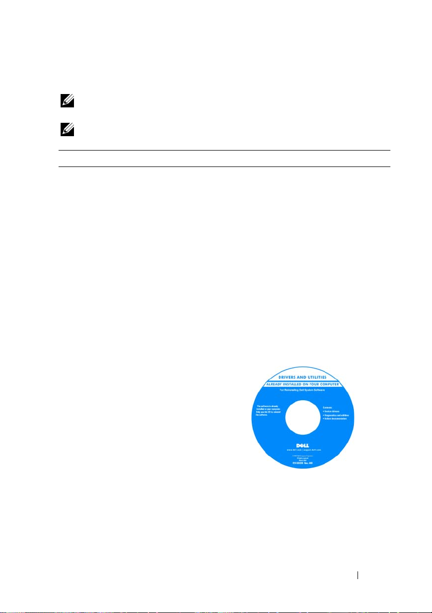
What Are You Looking For? Find It Here
• A diagnostic program for my computer
• Drivers for my computer
• Desktop System Software (DSS)
Drivers and Utilities Media
NOTE: The Drivers and Utilities media may
be optional and may not ship with your
computer.
Documentation and drivers are already
installed on your computer. You can use
the media to reinstall drivers (see
"Reinstalling Drivers and Utilities" on
page 118). To run the Dell Diagnostics,
see "Dell Diagnostics" on page 95.
Readme files may be included on your
media to provide last-minute updates
about technical changes to your computer
or advanced technical-reference material
for technicians or experienced users.
NOTE: Drivers and documentation updates
can be found at support.dell.com.
Finding Information 11
Page 12
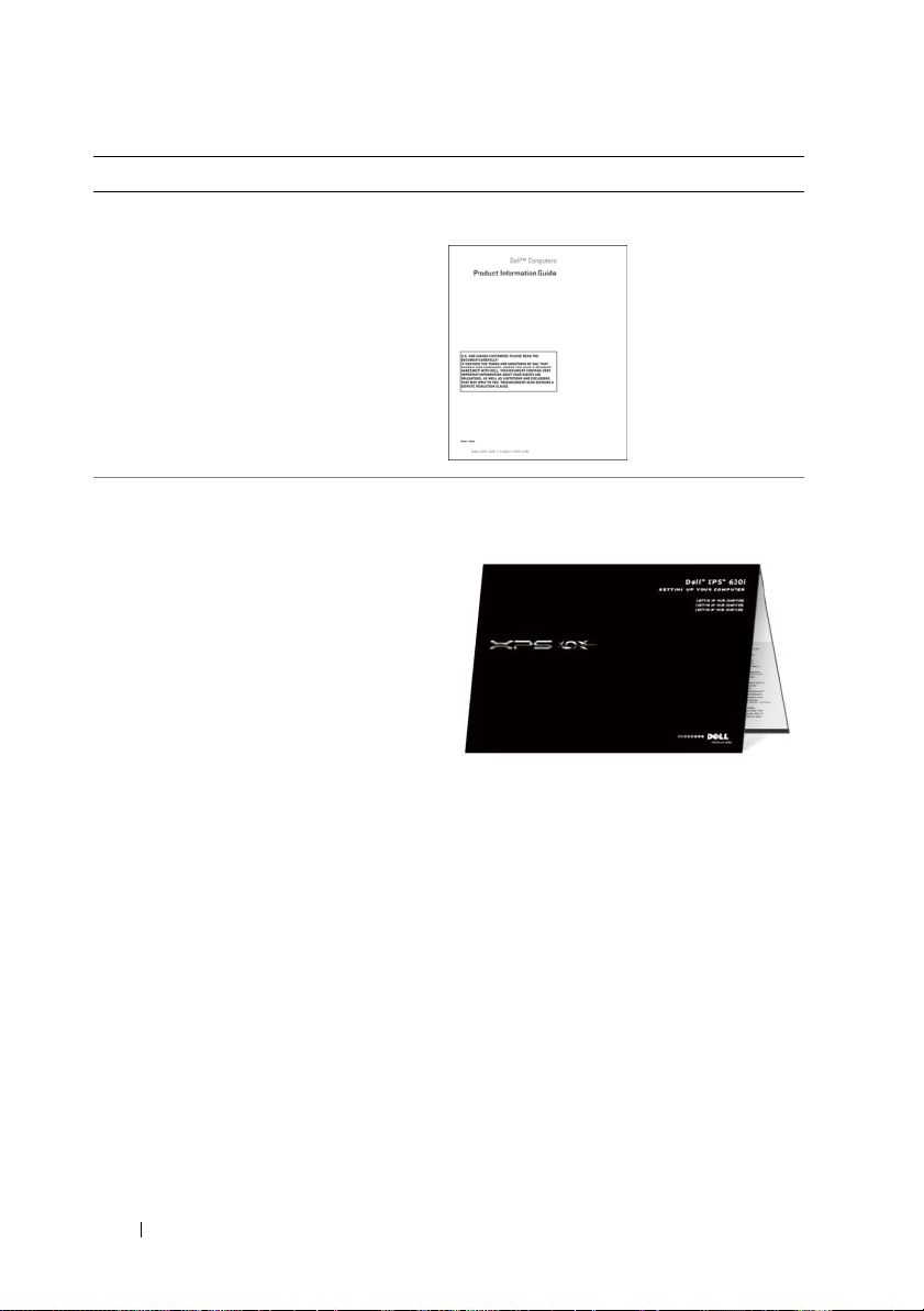
What Are You Looking For? Find It Here
• Warranty information
• Terms and Conditions (U.S. only)
• Safety instructions
• Regulatory information
• Ergonomics information
• End User License Agreement
Dell™ Product Information Guide
• How to set up my computer
Setup Diagram
12 Finding Information
Page 13
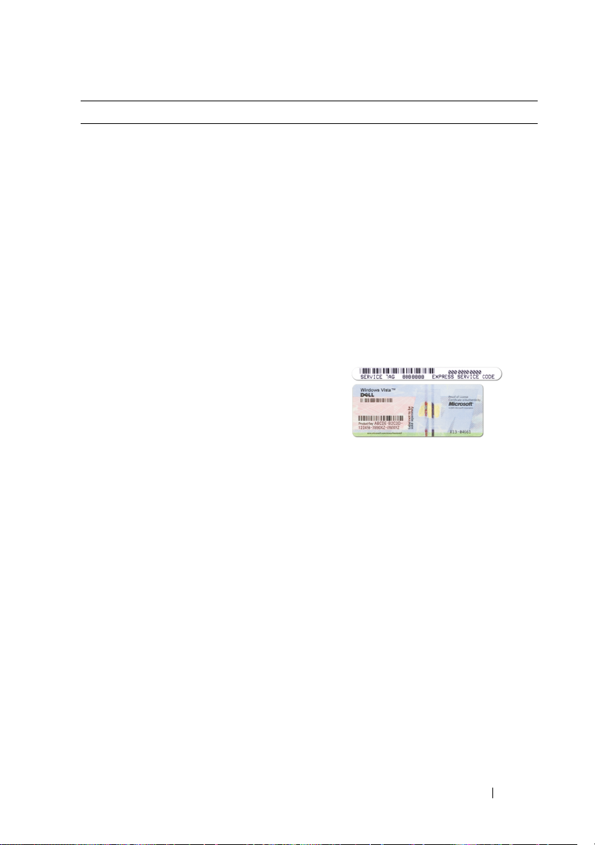
What Are You Looking For? Find It Here
• Service Tag and Express Service Code
• Microsoft Windows License Label
Service Tag and Microsoft® Windows®
License
NOTE: Your computer’s Service Tag and
Microsoft
located on your computer.
Your computer’s Service Tag contains
both a Service Tag number and an Express
Service Code.
• Use the Service Tag to identify your
computer when you use
support.dell.com
• Enter the Express Service Code to direct
your call when contacting support.
• Use the product key on the License
Label if you need to reinstall your
operating system.
NOTE: As an increased security measure,
the newly designed Microsoft Windows
license label incorporates a missing portion
or "hole" to discourage removal of the label.
®
Windows® License labels are
or contact support.
Finding Information 13
Page 14

What Are You Looking For? Find It Here
• Solutions — Troubleshooting hints and
tips, articles from technicians, and online
courses, frequently asked questions
• Community — Online discussion with
Dell Support Website — support.dell.com
NOTE: Select your region or business
segment to view the appropriate support
site.
other Dell customers
• Upgrades — Upgrade information for
components, such as memory, the hard
drive, and the operating system
• Customer Care — Contact information,
service call and order status, warranty,
and repair information
• Service and support — Service call status
and support history, service contract,
online discussions with technical support
• Dell Technical Update Service —
Proactive e-mail notification of software
and hardware updates for your computer
• Reference — Computer documentation,
details on my computer configuration,
product specifications, and white papers
• Downloads — Certified drivers, patches,
and software updates
• Desktop System Software (DSS)— If
you reinstall the operating system for
your computer, you should also reinstall
the DSS utility. DSS provides critical
updates for your operating system and
support for processors, optical drives,
USB devices, and so on. DSS is
necessary for correct operation of your
Dell computer. The software
automatically detects your computer
and operating system and installs the
updates appropriate for your
configuration.
To download Desktop System Software:
1
Go to
support.dell.com
Drivers and Downloads
2
Click
Select Model
3
Select your product model and click
Confirm
Go
.
4
Click
System Utilities
5
Click
Desktop System Software
Dell - Utility
6
Click
Run
save the driver to your computer.
NOTE: The support.dell.com user interface
may vary depending on your selections.
and click
.
.
, or enter a service tag and click
.
under
, and click
to run the driver, or
Download Now
Save
to
.
14 Finding Information
Page 15

What Are You Looking For? Find It Here
• How to find information about my
computer and its components
• How to connect to the Internet
• How to add user accounts for different
people
• How to transfer files and settings from
another computer
Windows Welcome Center
The Windows Welcome Center
automatically appears when you use the
computer for the first time. You can
choose to have it appear every time you
start your Tablet-PC by placing a check in
the Run at startup checkbox. Another
method of accessing the Welcome Center
is to click the Windows Vista Start button
™, and then click Welcome Center.
• How to use Microsoft Windows XP or
Windows Vista
®
• How to work with programs and files
• How to personalize my desktop
Windows Help and Support
Microsoft Windows XP:
1
Click the
and Support
2
Either select one of the topics listed, or
type a word or phrase that describes your
problem into the
arrow icon, and then click the topic that
describes your problem.
3
Follow the instructions on the screen.
Windows Vista:
1
Click the Windows Vista Start button
, and then click
2
In
Search Help
describes your problem, and then press
<Enter> or click the magnifying glass.
3
Click the topic that describes your
problem.
4
Follow the instructions on the screen.
Start
button and click
.
Search
box, click the
Help and Support
, type a word or phrase that
Help
.
Finding Information 15
Page 16
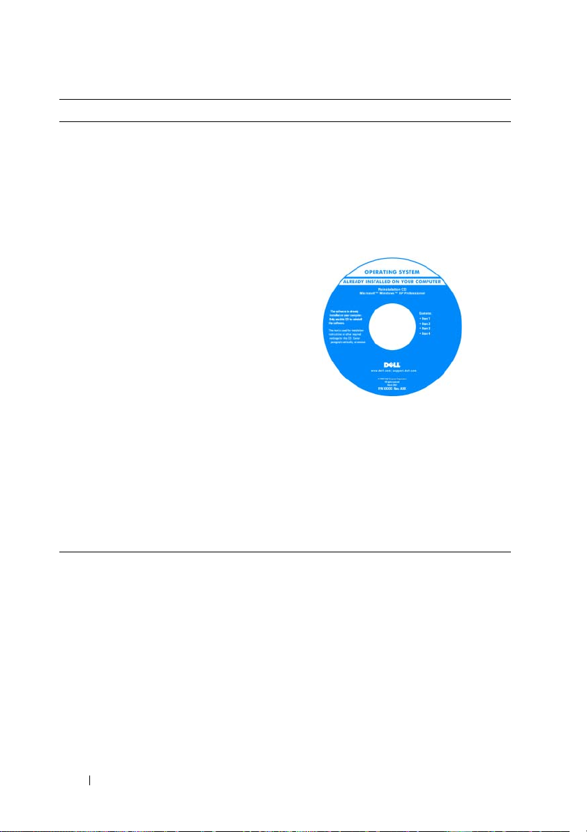
What Are You Looking For? Find It Here
• How to reinstall my operating system
Operating System Media
The operating system is already installed
on your computer. To reinstall your
operating system, use the Operating
System media. See "Restoring Your
Operating System" on page 122 in your
User’s Guide or Owner’s Manual.
After you reinstall your operating system,
use the Drivers and Utilities media to
reinstall drivers for the devices that came
with your computer.
Your operating system product key label is
located on your computer.
NOTE: The color of your CD varies based
on the operating system you ordered.
16 Finding Information
Page 17
About Your Computer
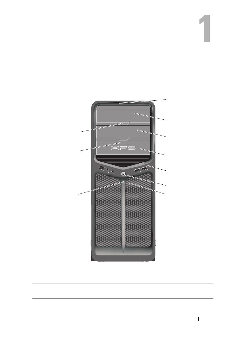
Front View of the Computer
1
2
10
9
8
1 front-panel LEDs (3) Multi-colored lights provide illumination for the front of
the computer.
2 optical-drive panel This panel covers the optical drive. Use the optical
drive to play a CD/DVD.
3
4
5
6
7
About Your Computer 17
Page 18

3 optional optical-drive
bay
4 FlexBay drive Supports a floppy drive, a Media Card Reader, or an
5 front I/O connectors Plug USB and other devices into the appropriate
6 power button Press to turn on the computer.
Supports an optical drive.
additional hard drive.
connectors (see "Front-Panel Connectors" on page 20).
NOTICE: To avoid losing data, do not use the
power button to turn off the computer. Instead,
perform an operating system shutdown.
NOTICE: If your operating system has ACPI
enabled, when you press the power button the
computer will perform an operating system
shutdown.
NOTE: The power button can also be used to wake the
system or to place it into a power-saving state (see
"Power Management" on page 38 for more information).
7 front-panel LEDs (4) Multi-colored lights provide illumination for the front of
the computer.
8 power light The power light illuminates or remains solid to
indicate different states:
• No light — The computer is turned off.
• White light— The computer is in a normal
operating state.
• Blinking white light— The computer is in a
power-saving state.
To exit from a power-saving state, press the power
button or use the keyboard or mouse if it is configured
as a wake device in the Windows Device Manager. For
more information about sleep states and exiting from a
power-saving state, see "Power Management" on
page 38.
9 FlexBay drive eject
button
10 optical drive panel
eject button (2)
Press here to open or close the floppy/media card
reader panel.
Press here to open/close the optical drive.
18 About Your Computer
Page 19
Back View of the Computer
5
1
2
3
4
About Your Computer 19
Page 20
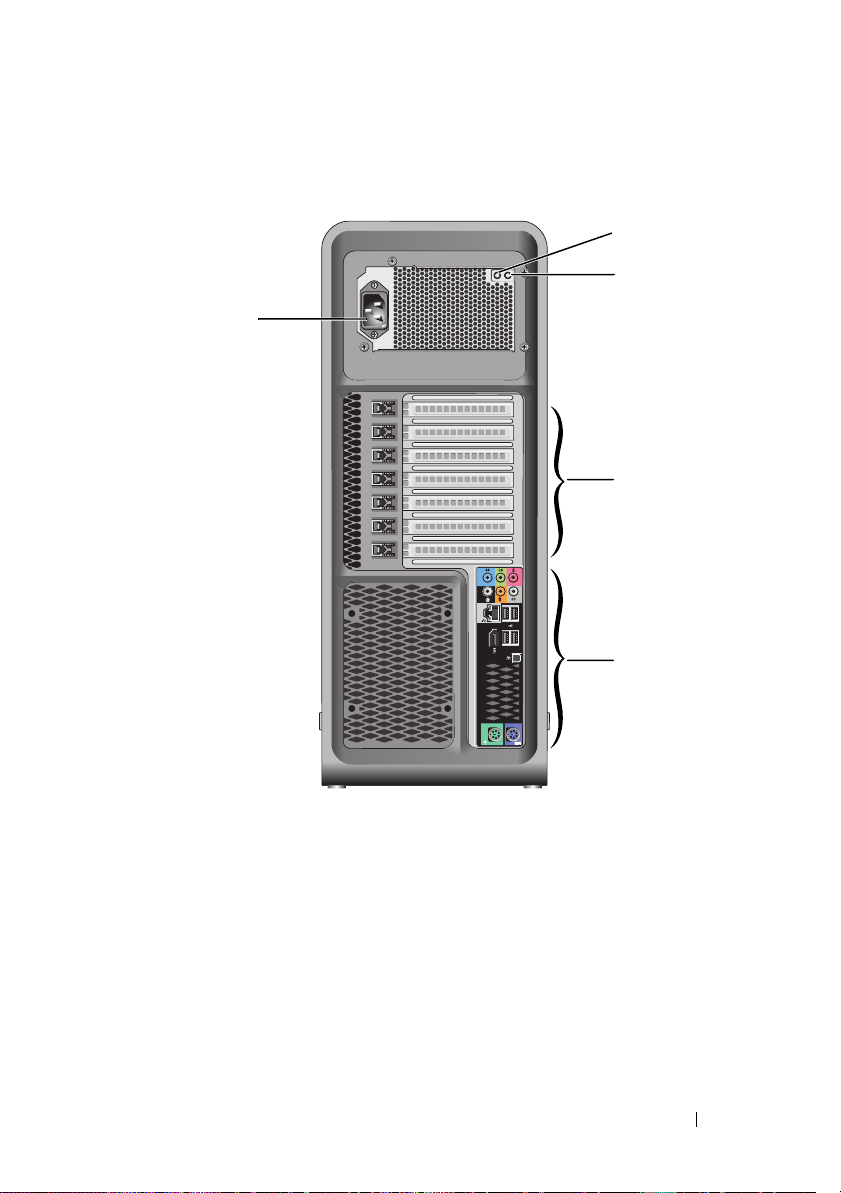
1 power supply test
switch
2 power supply
diagnostic LED
3 card slots Access connectors for any installed PCI or PCI Express cards.
Used to test the power supply.
Indicates power availability for power supply.
• Green light — Indicates power availability for power supply.
• No light — Indicates no power available for the power
supply or the power supply is not working. For more
information, see "Power Lights" on page 89.
NOTE: Some connector slots support full-length cards.
4 back I/O
connectors
5 power connector Insert the power cable. The appearance of this connector
Plug USB and other devices into the appropriate
connectors (see "Back-Panel Connectors" on page 21).
may differ from what is pictured.
Front-Panel Connectors
12
3
20 About Your Computer
4
Page 21
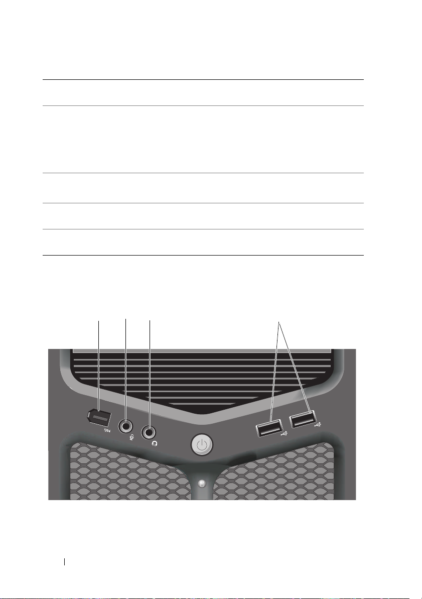
1 IEEE 1394 connector Use the optional IEEE 1394 connector for high-speed
data devices such as digital video cameras and external
storage devices.
2 microphone connector Use the microphone connector to attach a personal
computer microphone for voice or musical input into a
sound or telephony program.
3 headphone connector Use the headphone connector to attach headphones or
external speakers.
4 USB 2.0 connectors (2) Use the front USB connectors for devices that you
connect occasionally, such as flash memory keys or
cameras, or for bootable USB devices (see "System
Setup" on page 77 for more information on booting to
a USB device).
NOTE: It is recommended that you use the back USB
connectors for devices that typically remain connected,
such as printers and keyboards.
Back-Panel Connectors
1
14
2
3
4
5
6
7
8
9
13
12
11
10
About Your Computer 21
Page 22

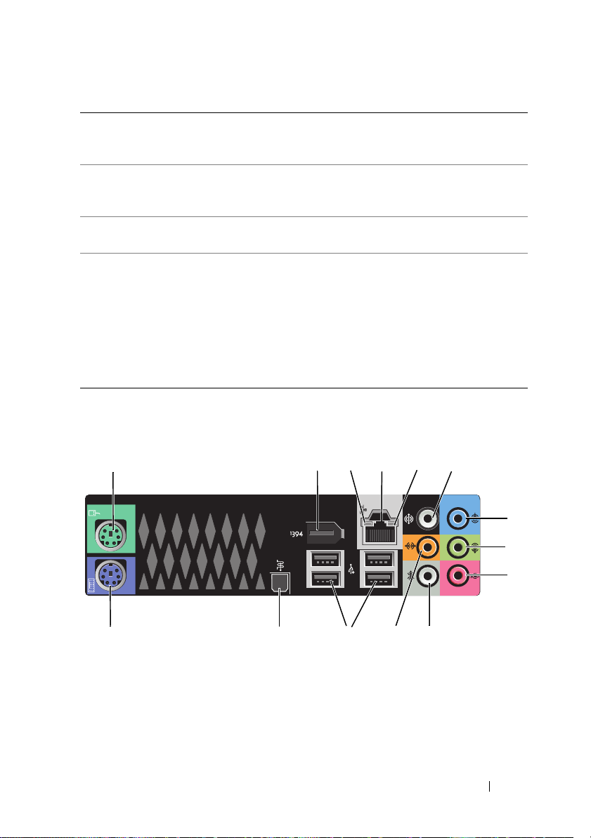
1 mouse connector Plug a standard PS/2 mouse into the green mouse connector.
Turn off the computer and any attached devices before you
connect a mouse to the computer. If you have a USB mouse,
plug it into a USB connector.
2 IEEE 1394
connector
3 network activity
light
4 network adapter
connector
5 link integrity light
6 surround sound
connector
Use the IEEE 1394 connector for high-speed data devices
such as digital video cameras and external storage devices.
The network activity light is on (flashing) when the
computer is transmitting or receiving network data. A high
volume of network traffic may make this light appear to be
in a steady on state.
To attach your computer to a network or broadband device,
connect one end of a network cable to either a network jack
or your network or broadband device. Connect the other
end of the network cable to the network adapter connector
on your computer. A click indicates that the network cable
has been securely attached.
NOTICE: Do not plug a telephone cable into the network
connector.
On computers with an additional network connector card,
use the connectors on the card and on the back of the
computer when setting up multiple network connections
(such as a separate intra- and extranet).
It is recommended that you use Category 5 wiring and
connectors for your network. If you must use Category 3
wiring, force the network speed to 10 Mbps to ensure
reliable operation.
• Green — A good connection exists between a 10-Mbps
network and the computer.
• Orange — A good connection exists between a 100-Mbps
network and the computer.
• Yellow — A good connection exists between a 1000-Mbps
(or 1-Gbps) network and the computer.
• Off — The computer is not detecting a physical
connection to the network.
Use the (black) surround sound connector to attach
multichannel-capable speakers.
22 About Your Computer
Page 23

7 line-in connector Use the (blue) line-in connector to attach a record/playback
device such as a cassette player, CD player, or VCR. On
computers with a sound card, use the connector on the card.
8line-
out/headphone
connector
9 microphone
connector
10 side surround
sound connector
11 center
subwoofer/LFE
connector
12 USB 2.0
connectors (4)
Use the (green) line-out connector to attach headphones
and speakers with integrated amplifiers. On computers with
a sound card, use the connector on the card.
Use the (pink) microphone connector to attach a personal
computer microphone for voice or musical input into a
sound or telephony program.
Use the (silver) side surround connector to attach additional
speakers.
Use the (orange) subwoofer connector to attach a single
subwoofer.
NOTE: The LFE (Low Frequency Effects) Audio channel, found
in digital surround sound audio schemes, carries only low
frequency information of 80 Hz and below. The LFE channel
drives a subwoofer to provide extremely low bass extension.
Systems not using subwoofers can shunt the LFE information
to the main speakers in the surround sound setup.
Use the back USB connectors for devices that typically
remain connected, such as printers and keyboards.
NOTE: It is recommended that you use the front USB
connectors for devices that you connect occasionally, such as
flash memory keys or cameras, or for bootable USB devices.
13 optical S/PDIF
connector
14 keyboard
connector
Use the optical S/PDIF connector to transmit digital audio
without going through an analog audio conversion process.
Plug a standard PS/2 keyboard into the purple keyboard
connector. Turn off the computer and any attached devices
before you connect a keyboard to the computer. If you have
a USB keyboard, plug it into a USB connector.
About Your Computer 23
Page 24

24 About Your Computer
Page 25

Setting Up Your Computer
Installing Your Computer in an Enclosure
Installing your computer in an enclosure can restrict the airflow and impact
your computer’s performance, possibly causing it to overheat. Follow the
guidelines below when installing your computer in an enclosure:
NOTICE: The operating temperature specifications indicated in this manual
reflects the maximum ambient operating temperature. The room ambient
temperature needs to be a consideration when installing your computer in an
enclosure. For example, if the ambient room temperature is at 25°C (77°F),
depending on your computer’s specifications, you only have 5° to 10°C (9° to 18°F)
temperature margin before you reach your computer’s maximum operating
temperature. For details about your computer’s specifications, see "Specifications"
on page 129.
• Leave a 10.2 cm (4 inches) minimum clearance on all vented sides of the
computer to permit the airflow required for proper ventilation.
• If your enclosure has doors, they need to be of a type that allows at least
30 percent airflow through the enclosure (front and back).
Setting Up Your Computer 25
Page 26
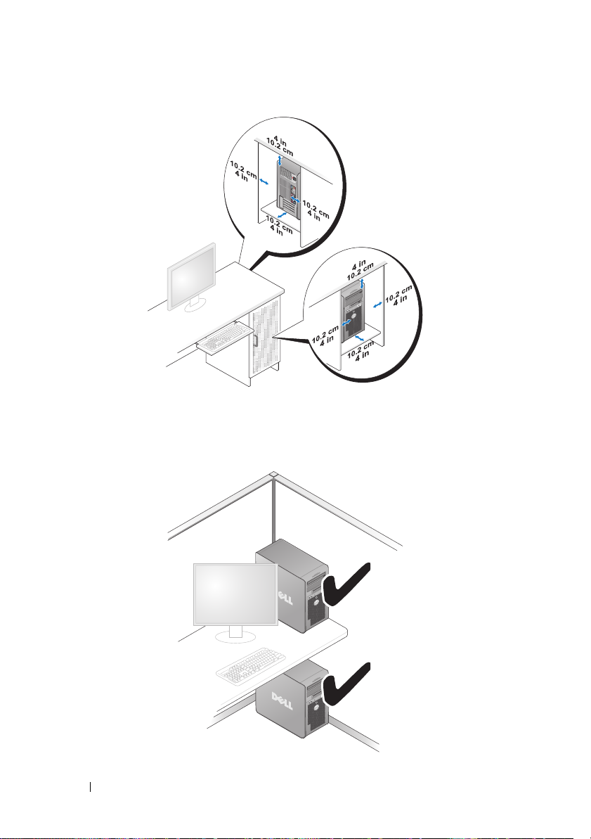
• If your computer is installed in a corner on a desk or under a desk, leave at
least 5.1 cm (2 in) clearance from the back of the computer to the wall to
permit the airflow required for proper ventilation.
26 Setting Up Your Computer
Page 27
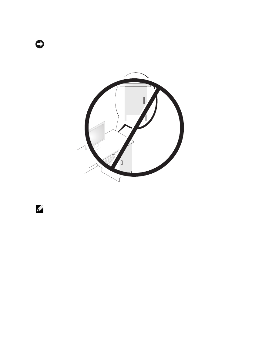
NOTICE: Do not install your computer in an enclosure that does not allow airflow.
Restricting the airflow impacts your computer’s performance, possibly causing it to
overheat.
Connecting to the Internet
NOTE: ISPs and ISP offerings vary by country.
To connect to the Internet, you need a modem or network connection and an
Internet service provider (ISP). Your ISP will offer one or more of the
following Internet connection options:
• DSL connections that provide high-speed Internet access through your
existing telephone line or cellular telephone service. With a DSL
connection, you can access the Internet and use your telephone on the
same line simultaneously.
• Cable modem connections that provide high-speed Internet access
through your local cable TV line.
• Satellite modem connections that provide high-speed Internet access
through a satellite television system.
Setting Up Your Computer 27
Page 28

• Dial-up connections that provide Internet access through a telephone line.
Dial-up connections are considerably slower than DSL and cable (or satellite)
modem connections.
• Wireless LAN connections that provide Internet access using Bluetooth
®
wireless technology.
If you are using a dial-up connection, connect a telephone line to the modem
connector on your computer and to the telephone wall jack before you set up
your Internet connection. If you are using a DSL or cable/satellite modem
connection, contact your ISP or cellular telephone service for setup instructions.
Setting Up Your Internet Connection
To set up an Internet connection with a provided ISP desktop shortcut:
1
Save and close any open files, and exit any open programs.
2
Double-click the ISP icon on the Microsoft® Windows® desktop.
3
Follow the instructions on the screen to complete the setup.
If you do not have an ISP icon on your desktop or if you want to set up an
Internet connection with a different ISP, perform the steps in the following
section that corresponds to the operating system your computer is using.
NOTE: If you are having problems connecting to the Internet, see "Error Messages"
on page 103. If you cannot connect to the Internet but have successfully connected
in the past, the ISP might have a service outage. Contact your ISP to check the
service status, or try connecting again later.
Windows XP
1
Save and close any open files, and exit any open programs.
2
Click
Start→
The
New Connection Wizard
3
Click
Connect to the Internet
4
In the next window, click the appropriate option:
• If you do not have an ISP and want to select one, click
list of Internet service providers (ISPs)
Internet Explorer
.
appears.
.
Choose from a
.
• If you have already obtained setup information from your ISP but you
did not receive a setup CD, click
• If you have a CD, click
Use the CD I got from an ISP
Set up my connection manually
.
28 Setting Up Your Computer
.
Page 29

5
Click
Next
.
If you selected
Set up my connection manually
, continue to step 6.
Otherwise, follow the instructions on the screen to complete the setup.
NOTE: If you do not know which type of connection to select, contact your ISP.
6
Click the appropriate option under
Internet?
7
Use the setup information provided by your ISP to complete the setup.
, and then click
Next
How do you want to connect to the
.
Windows Vista
NOTE: Have your ISP information ready. If you do not have an ISP, the Connect to
the Internet wizard can help you get one.
1
Save and close any open files, and exit any open programs.
2
Click the Windows Vista Start button , and click
3
Under
The
4
Click either
®
Network and Internet,
Connect to the Internet
Broadband (PPPoE)
click
Connect to the Internet
window appears.
or
Dial-up
, depending on how you want
Control Panel
.
to connect:
•Choose
Broadband
if you will use a DSL, satellite modem, cable TV
modem, or Bluetooth wireless technology connection.
• Chose
NOTE: If you do not know which type of connection to select, click Help me choose
or contact your ISP.
5
Follow the instructions on the screen and use the setup information
Dial-up
if you will use a dial-up modem or ISDN.
provided by your ISP to complete the setup.
Transferring Information to a New Computer
You can use your operating system "wizards" to help you transfer files and
other data from one computer to another—for example, from an old
computer to a new computer. For instructions, see the following section that
corresponds to the operating system that your computer is running.
Setting Up Your Computer 29
Page 30

Microsoft® Windows® XP
The Microsoft Windows XP operating system provides the Files and Settings
Transfer Wizard to move data from a source computer to a new computer.
You can transfer data, such as:
• E-mail messages
• Toolbar settings
• Window sizes
• Internet bookmarks
You can transfer the data to the new computer over a network or serial
connection, or you can store it on removable media, such as a writable CD,
for transfer to the new computer.
NOTE: You can transfer information from an old computer to a new computer by
directly connecting a serial cable to the input/output (I/O) ports of the two
computers. To transfer data over a serial connection, you must access the Network
Connections utility from the Control Panel and perform additional configuration
steps, such as setting up an advanced connection and designating the host
computer and the guest computer.
For instructions on setting up a direct cable connection between two computers,
see Microsoft Knowledge Base Article #305621, titled How to Set Up a Direct Cable
Connection Between Two Computers in Windows XP. This information may not be
available in certain countries.
For transferring information to a new computer, you must run the Files and
Settings Transfer Wizard. You can use the optional Operating System media
for this process or you can create a wizard disk with the Files and Settings
Transfer Wizard.
Running the Files and Settings Transfer Wizard With the Operating System Media
NOTE: This procedure requires the Operating System media.
To prepare a new computer for the file transfer:
1
Open the Files and Settings Transfer Wizard: click
Accessories→ System Tools→
2
When the
click
Files and Settings Transfer Wizard
Next
.
Files and Settings Transfer Wizard
Start→
All Programs→
.
welcome screen appears,
30 Setting Up Your Computer
Page 31

3
On the
4
On the
from the Windows XP CD
5
When the
source computer. Do
Which computer is this?
screen, click
Do you have a Windows XP CD?
→ Next
.
Now go to your old computer
not
click
Next
at this time.
New Computer→
screen, click
I will use the wizard
screen appears, go to your old or
To copy data from the old computer:
On the old computer, insert the Windows XP
1
2
On the
additional tasks
3
Under
4
On the
5
On the
6
On the
transfer and click
Welcome to Microsoft Windows XP
.
What do you want to do?
Which computer is this?
Select a transfer method
, click
screen, click
screen, click the transfer method you prefer.
What do you want to transfer?
Next
.
After the information has been copied, the
screen, select the items you want to
Operating System
screen, click
Perform
Transfer files and settings→ Next
Old Computer→
Completing the Collection Phase
screen appears.
7
Click
Finish
.
To transfer data to the new computer:
1
On the
click
2
On the
chose for transferring your settings and files and click
Now go to your old computer
Next
.
Where are the files and settings?
screen on the new computer,
screen, select the method you
Next
.
The wizard reads the collected files and settings and applies them to your
new computer.
Next
media.
Next
.
.
.
When all of the settings and files have been applied, the
appears.
3
Click
Finished
and restart the new computer.
Setting Up Your Computer 31
Finished
screen
Page 32

Running the Files and Settings Transfer Wizard Without the
Operating System Media
To run the Files and Settings Transfer Wizard without the Operating System
media, you must create a wizard disk that will allow you to create a backup
image file to removable media.
To create a wizard disk, use your new computer with Windows XP and
perform the following steps:
1
Open the Files and Settings Transfer Wizard: click
Accessories→ System Tools→
2
When the
click
3
On the
4
On the
Files and Settings Transfer Wizard
Next
.
Which computer is this?
Do you have a Windows XP CD?
Wizard Disk in the following drive
5
Insert the removable media, such as a writable CD, and click OK.
6
When the disk creation completes and the
computer
7
Go to the old computer.
message appears,
Files and Settings Transfer Wizard
screen, click
screen, click
→
Next.
do not
click
Next
Start→
All Programs→
.
welcome screen appears,
New Computer→
Next
.
I want to create a
Now go to your old
.
To copy data from the old computer:
On the old computer, insert the wizard disk.
1
2
Click
Start→
3
In the
the appropriate removable media) and click
4
On the
5
On the
6
On the
7
On the
transfer and click
After the information has been copied, the
Run
.
Open
field on the
Run
window, browse to the path for
Files and Settings Transfer Wizard
Which computer is this?
Select a transfer method
What do you want to transfer?
Next
.
screen, click
screen, click the transfer method you prefer.
screen, select the items you want to
fastwiz
(on
OK
.
welcome screen, click
Old Computer→
Next
Next
.
.
Completing the Collection Phase
screen appears.
8
Click
Finish
.
32 Setting Up Your Computer
Page 33

To transfer data to the new computer:
1
On the
Now go to your old computer
2
On the
Where are the files and settings?
chose for transferring your settings and files and click
screen on the new computer, click
screen, select the method you
Next
. Follow the
instructions on the screen.
The wizard reads the collected files and settings and applies them to your
new computer.
Next
.
When all of the settings and files have been applied, the
Finished
screen
appears.
3
Click
Finished
NOTE: For more information about this procedure, search support.dell.com for
document #154781 (What Are The Different Methods To Transfer Files From My Old
Computer To My New Dell™ Computer Using the Microsoft
Operating System?).
NOTE: Access to the Dell™ Knowledge Base document may not be available in
certain countries.
and restart the new computer.
®
Windows® XP
Windows Vista
1
Click the Windows Vista Start button , and then click
and settings
2
In the
3
Click
→ Start Windows Easy Transfer.
User Account Control
Start a new transfer
dialog box, click
or
Continue a transfer in progress
Continue
Transfer files
.
.
Follow the instructions provided on the screen by the Windows Easy Transfer
wizard.
Setting Up a Printer
NOTICE: Complete the operating system setup before you connect a printer to the
computer.
See the documentation that came with the printer for setup information,
including how to:
• Obtain and install updated drivers.
• Connect the printer to the computer.
• Load paper and install the toner or ink cartridge.
Setting Up Your Computer 33
Page 34
For technical assistance, refer to the printer owner's manual or contact the
printer manufacturer.
Printer Cable
Your printer connects to your computer with either a USB cable or a parallel
cable. Your printer may not come with a printer cable, so if you purchase a
cable separately, ensure that it is compatible with your printer and computer.
If you purchased a printer cable at the same time you purchased your
computer, the cable may arrive in the computer’s shipping box.
Connecting a USB Printer
NOTE: You can connect USB devices while the computer is turned on.
1
Complete the operating system setup if you have not already done so.
2
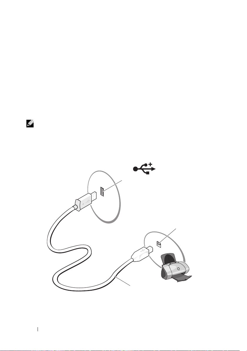
Attach the USB printer cable to the USB connectors on the computer and
the printer. The USB connectors fit only one way.
1
1 USB connector on computer 2 USB connector on printer
3 USB printer cable
34 Setting Up Your Computer
2
3
Page 35

3
Turn on the printer and then turn on the computer.
4
Depending on your computer’s operating system, a printer wizard may be
available to help you install the printer driver:
If your computer is running the Microsoft® Windows® XP operating system
and the
Add New Hardware Wizard
window appears, click
Cancel
.
If your computer is running the Windows Vista® operating system
Windows Vista Start button , and click
Network→ Add a printer
, click the
to
start the Add Printer Wizard.
5
Install the printer driver if necessary. See "Reinstalling Drivers and
Utilities" on page 118 and the documentation that came with your printer.
Connecting Two Monitors
CAUTION: Before you begin any of the procedures in this section, follow the
safety instructions in the Product Information Guide.
If you purchased a graphics card that supports dual monitors, follow these
instructions to connect and enable your monitors. The instructions tell you
how to connect either two monitors (each with a VGA connector), one monitor
with a VGA connector and one monitor with a DVI connector, or a TV.
NOTICE: If you are connecting two monitors that have VGA connectors, you must
have the optional DVI adapter to connect the cable. If you are connecting two
flat-panel monitors, at least one of them must have a VGA connector. If you are
connecting a TV, you may connect only one monitor (VGA or DVI) in addition to the TV.
Connecting Two Monitors With VGA Connectors
1
Shutdown your system.
NOTE: If your computer has integrated video, do not connect either monitor to the
integrated video connector. If the integrated video connector is covered by a cap,
do not remove the cap to connect the monitor or the monitor will not function.
2
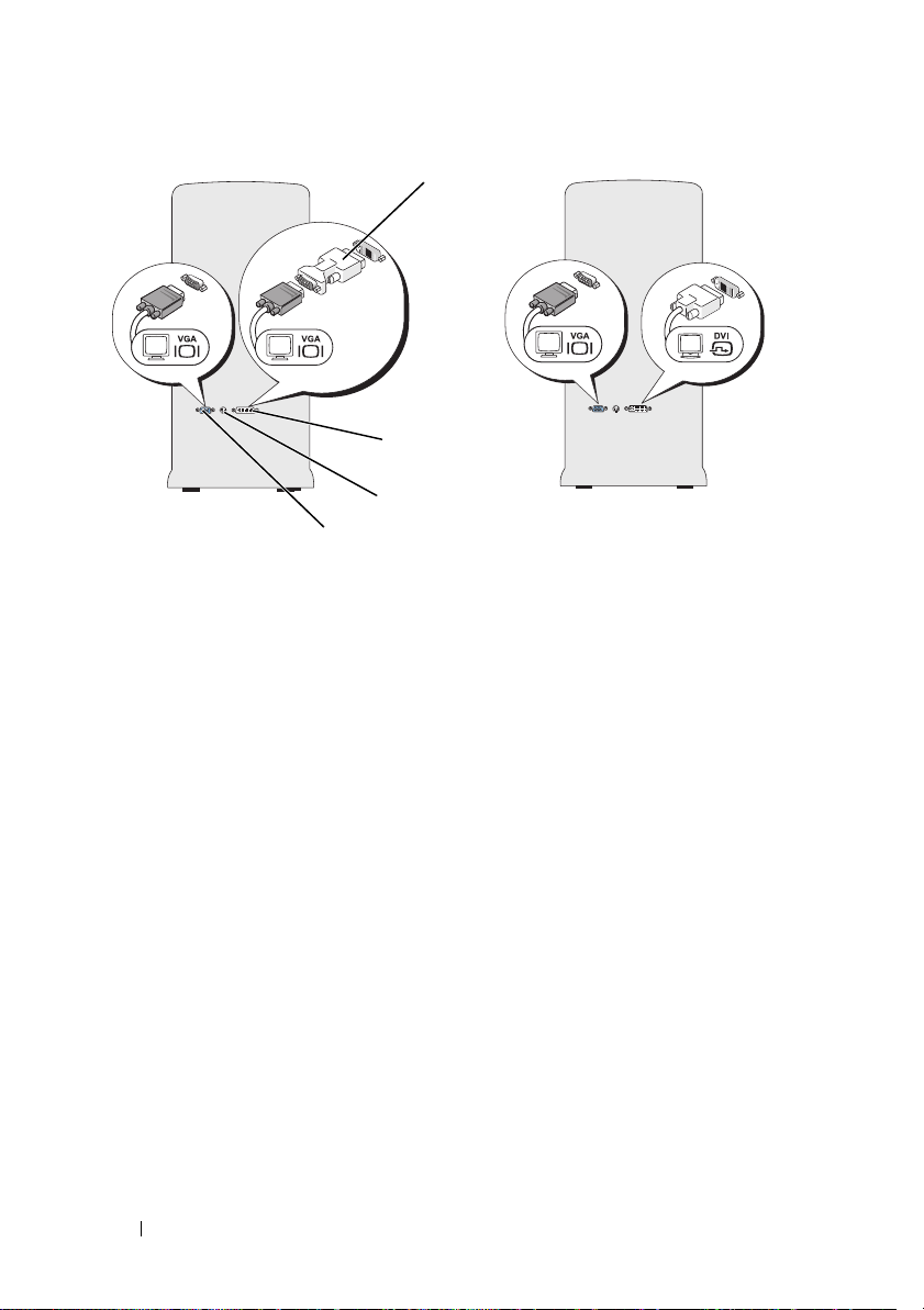
Connect one of the monitors to the VGA (blue) connector on the back of
the computer.
3
Connect the other monitor to the optional DVI adapter and connect the
DVI adapter to the DVI (white) connector on the back of the computer.
4
Restart your system.
Setting Up Your Computer 35
Page 36
2*
1
3*
4
*May not be present on your computer
1 optional DVI adapter 2 DVI (white) connector
3 TV-OUT connector 4 VGA (blue) connector
Connecting One Monitor With a VGA Connector and One Monitor With a DVI Connector
1
Shutdown your system.
2
Connect the VGA connector on the monitor to the VGA (blue) connector
on the back of the computer.
3
Connect the DVI connector on the other monitor to the DVI (white)
connector on the back of the computer.
4
Restart your system.
36 Setting Up Your Computer
Page 37

Connecting a TV
NOTE: You must purchase an S-video cable, available at most consumer electronics
stores, to connect a TV to your computer. It is not included with your computer.
1
Shutdown your system.
2
Connect one end of the S-video cable to the optional TV-OUT connector
on the back of the computer.
3
Connect the other end of the S-video cable to the S-video input connector
on your TV.
4
Connect the VGA or DVI monitor.
5
Restart your system.
Changing the Display Settings
1
After you connect the monitor(s) or TV, turn on the computer.
The Microsoft
2
Enable extended desktop mode in the display settings. In extended
desktop mode, you can drag objects from one screen to the other,
effectively doubling the amount of viewable work space.
®
Windows® desktop displays on the primary monitor.
Power Protection Devices
Several devices are available to protect against power fluctuations and
failures:
• Surge protectors
• Line conditioners
• Uninterruptible power supplies (UPS)
Surge Protectors
Surge protectors and power strips equipped with surge protection help
prevent damage to your computer from voltage spikes that can occur during
electrical storms or after power interruptions. Some surge protector
manufacturers include warranty coverage for certain types of damage.
Carefully read the device warranty when choosing a surge protector. A device
with a higher joule rating offers more protection. Compare joule ratings to
determine the relative effectiveness of different devices.
Setting Up Your Computer 37
Page 38

NOTICE: Most surge protectors do not protect against power fluctuations or
power interruptions caused by nearby lightning strikes. When lightning occurs in
your area, disconnect the telephone line from the telephone wall jack and
disconnect your computer from the electrical outlet.
Many surge protectors have a telephone jack for modem protection. See the
surge protector documentation for modem connection instructions.
NOTICE: Not all surge protectors offer network adapter protection. Disconnect the
network cable from the network wall jack during electrical storms.
Line Conditioners
NOTICE: Line conditioners do not protect against power interruptions.
Line conditioners are designed to maintain AC voltage at a fairly constant level.
Uninterruptible Power Supplies
NOTICE: Loss of power while data is being saved to the hard drive may result in
data loss or file damage.
NOTE: To ensure maximum battery operating time, connect only your computer to
a UPS. Connect other devices, such as a printer, to a separate power strip that
provides surge protection.
A UPS protects against power fluctuations and interruptions. UPS devices
contain a battery that provides temporary power to connected devices when
AC power is interrupted. The battery charges while AC power is available. See
the UPS manufacturer documentation for information on battery operating time
and to ensure that the device is approved by Underwriters Laboratories (UL).
Power Management
Power Management Options in Windows XP
The Microsoft Windows XP power management features can reduce the
amount of electricity your computer uses when it is on and you are not using
it. You can reduce power to just the monitor or the hard drive, or you can use
standby mode or hibernate mode to reduce power to the entire computer.
When the computer exits from a power conservation mode, it returns to the
operating state it was in prior to entering the mode.
38 Setting Up Your Computer
Page 39

NOTE: Windows XP Professional includes security and networking features not
available in Windows XP Home Edition. When a Windows XP Professional
computer is connected to a network, different options related to security and
networking appear in certain windows.
NOTE: The procedures to activate the standby and hibernate modes may vary
according to your operating system.
Standby Mode
Standby mode conserves power by turning off the display and the hard drive
after a designated period of time, known as a time-out. When the computer
exits from standby mode, it returns to the operating state it was in prior to
entering standby mode.
NOTICE: If your computer loses power while in standby mode, it may lose data.
To set standby mode to automatically activate after a defined period of
inactivity:
1
Click
Maintenance
2
Under
Start→
Control Panel→
Pick a category→
.
or pick a Control Panel icon
, click
Power Options
Performance and
.
To immediately activate standby mode without a period of inactivity, click
→
Start
Turn Off Computer→ Stand by.
To exit from standby mode, press a key on the keyboard or move the mouse.
Hibernate Mode
Hibernate mode conserves power by copying system data to a reserved area on
the hard drive, and then completely turning off the computer. When the
computer exits from hibernate mode, the desktop is restored to the state it
was in
prior to entering hibernate mode.
To activate hibernate mode:
1
Click
Start→
Maintenance
2
Under
3
Define your hibernate settings on the
and
Hibernate
Control Panel→
Pick a category→
.
or pick a Control Panel icon
tab.
Performance and
, click
Power Options
Power Schemes
Setting Up Your Computer 39
tab,
.
Advanced
tab,
Page 40

To exit from hibernate mode, press the power button. The computer may
take a short time to exit from hibernate mode. Because the keyboard and
mouse do not function in hibernate mode, pressing a key on the keyboard or
moving the mouse does not bring the computer out of hibernation.
Because hibernate mode requires a special file on your hard drive with enough
disk space to store the contents of the computer memory, Dell creates an
appropriately sized hibernate mode file before shipping the computer to you.
If the computer’s hard drive becomes corrupted, Windows XP recreates the
hibernate file automatically.
Power Options Properties
Define your standby mode settings, hibernate mode settings, and other power
settings in the Power Options Properties window.
To access the Power
Options Properties window:
1
Click
Start→
Maintenance
2
Under
3
Define your power settings on the
Hibernate
Power Schemes Tab
Control Panel→
Pick a category→
.
or pick a Control Panel icon
tab.
, click
Power Options
Power Schemes
Performance and
.
tab,
Advanced
tab, and
Each standard power setting is called a scheme. If you want to select one of
the standard Windows schemes installed on your computer, choose a scheme
from the Power schemes drop-down menu. The settings for each scheme
appear in the fields below the scheme name. Each scheme has different
settings for starting standby mode, hibernate mode, turning off the monitor,
and turning off the hard drive.
NOTICE: If you set the hard drive to time-out before the monitor does, your
computer may appear to be locked up. To recover, press any key on the keyboard or
click the mouse. To avoid this problem, always set the monitor to time-out before the
hard drive.
The Power schemes drop-down menu displays the following schemes:
•
Always On
(default) — If you want to use your computer with no power
conservation.
•
Home/Office Desk
— If you want your home or office computer to run
with little power conservation.
40 Setting Up Your Computer
Page 41

•
Portable/Laptop
— If your computer is a portable computer that you use
for traveling.
•
Presentation
— If you want your computer to run without interruption
(using no power conservation).
•
Minimal Power Management
— If you want your computer to run with
minimal power conservation.
•
Max Battery
— If your computer is a portable computer and you run your
computer from batteries for an extended period of time.
If you want to change the default settings for a scheme, click the drop-down
menu in the Turn off monitor, Turn off hard disks, System stand by, or
System hibernates field, and then select a time-out from the displayed list.
Changing the time-out for a scheme field permanently changes the default
settings for that scheme, unless you click Save As and enter a new name for
the changed scheme.
Advanced Tab
The Advanced tab allows you to:
• Place the power options icon in the Windows taskbar for quick
access.
• Set the computer to prompt you for your Windows password before the
computer exits from standby mode or hibernate mode.
• Program the power button to activate standby mode, activate hibernate
mode, or turn off the computer.
To program these functions, click an option from the corresponding drop-down
menu and click OK.
Hibernate Tab
The Hibernate tab allows you to enable hibernate mode. If you want to use
the hibernate settings as defined on the Power Schemes tab, click the Enable
hibernate support check box on the Hibernate tab.
For more information on power management options:
1
Click
Start→
2
In the
your computer
Help and Support→
Performance and maintenance
Performance and maintenance
.
.
window, click
Setting Up Your Computer 41
Conserving power on
Page 42

Power Management Options in Windows Vista
The Microsoft Vista power management features can reduce the amount of
electricity your computer uses when it is on and you are not using it. You can
reduce power to just the monitor or the hard drive, or you can use sleep mode
or hibernate mode to reduce power to the entire computer. When the
computer exits from a power conservation mode, it returns to the operating
state it was in prior to entering the mode.
Sleep Mode
Sleep mode conserves power by turning off the display and the hard drive
after a predetermined period of inactivity (a time-out). When the computer
exits sleep mode, it returns to the same operating state it was in before
entering sleep mode.
To enter sleep mode in Windows Vista, click Start ,
lower-right corner of the Start menu, and then
click Sleep.
To exit sleep mode, press a key on the keyboard or move the mouse.
Hibernate Mode
Hibernate mode conserves power by copying system data to a reserved area on
the hard drive and then completely turning off the computer. When the
computer exits hibernate mode, it returns to the same operating state it was
in before entering hibernate mode.
To manually enter hibernate mode in Windows Vista, click Start ,
arrow in the lower-right corner of the Start menu, and then
click the arrow in the
click the
click Hibernate.
Configuring Power Management Settings
You can use the Windows Power Options Properties to configure the power
management settings on your computer.
To access Power Options Properties, click Start
→
Control Panel
→
System and Maintenance→ Power Options.
42 Setting Up Your Computer
Page 43
Using Multimedia
Playing CDs or DVDs
NOTICE: Do not press down on the CD/DVD tray when you open or close it. Keep
the tray closed when you are not using the drive.
NOTICE: Do not move the computer while playing CDs or DVDs.
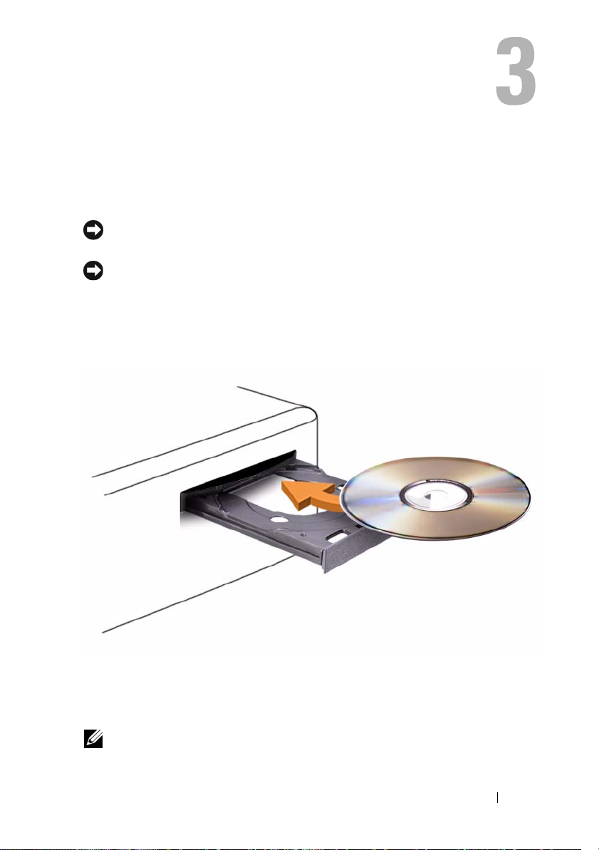
1
Press the eject button on the front of the drive.
2
Place the disc, label side up, in the center of the tray.
3
Press the eject button or gently push in the tray.
To format CDs for storing data, to create music CDs, or to copy CDs, see the
CD software that came with your computer.
NOTE: Ensure that you follow all copyright laws when you create CDs.
Using Multimedia 43
Page 44
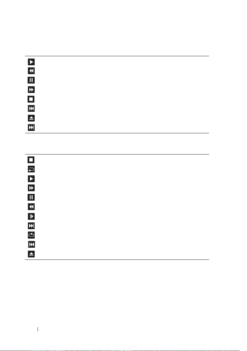
A CD player includes the following basic buttons:
Play.
Move backward within the current track.
Pause.
Move forward within the current track.
Stop.
Go to the previous track.
Eject.
Go to the next track.
A DVD player includes the following basic buttons:
Stop.
Restart the current chapter.
Play.
Fast forward.
Pause.
Fast reverse.
Advance a single frame while in pause mode.
Go to the next title or chapter.
Continuously play the current title or chapter.
Go to the previous title or chapter.
Eject.
For more information on playing CDs or DVDs, click Help on the CD or
DVD player (if available).
44 Using Multimedia
Page 45

Copying CDs and DVDs
NOTE: Ensure that you observe all copyright laws when creating CDs or DVDs.
This section applies only to computers that have a CD-RW, DVD+/-RW, or
CD-RW/DVD (combo) drive.
NOTE: The types of CD or DVD drives offered by Dell may vary by country.
The following instructions explain how to make an exact copy of a CD or
DVD using Roxio Creator Plus - Dell Edition. You can also use Roxio Creator
Plus for other purposes, such as creating music CDs from audio files stored on
your computer or backing up important data. For help, open Roxio Creator Plus,
and then click the question mark icon in the upper-right corner of the window.
How to Copy a CD or DVD
NOTE: CD-RW/DVD combo drives cannot write to DVD media. If you have a
CD-RW/DVD combo drive and you experience recording problems, check for
available software patches on the Sonic Support website at sonic.com.
The DVD-writable drives installed in Dell™ computers can write to and read
DVD+/-R, DVD+/-RW and DVD+R DL (dual layer) media, but cannot
write to and may not read DVD-RAM or DVD-R DL media.
NOTE: Most commercial DVDs have copyright protection and cannot be copied
using Roxio Creator Plus.
1
Open Roxio Creator Plus.
2
Under the
3
To copy the CD or DVD:
•
Copy
tab, click
If you have one CD/DVD drive
then click
Disc Copy
Disc Copy
.
, ensure that the settings are correct, and
. The computer reads your source CD or DVD
and copies the data to a temporary folder on your computer hard drive.
When prompted, insert a blank CD or DVD into the drive and click
OK
.
•
If you have two CD/DVD drives
inserted your source CD or DVD, and then click
, select the drive into which you have
Disc Copy
. The
computer copies the data from the source CD or DVD to the blank
CD or DVD.
Once you have finished copying the source CD or DVD, the CD or DVD
that you have created automatically ejects.
Using Multimedia 45
Page 46

Using Blank CDs and DVDs
CD-RW drives can write to CD recording media only (including high-speed
CD-RW media) while DVD-writable drives can write to both CD and DVD
recording media.
Use blank CD-Rs to record music or permanently store data files. After the
maximum storage capacity of a CD-R is reached, you cannot write to that
CD-R again (see the Sonic documentation for more information). Use blank
CD-RWs if you plan to erase, rewrite, or update information on the CD later.
Blank DVD+/-Rs can be used to permanently store large amounts of data.
After you create a DVD+/-R disc, you may not be able to write to that disc
again if the disc is finalized or closed during the final stage of the disc creation
process. Use blank DVD+/-RWs if you plan to erase, rewrite, or update
information on the disc later.
CD-Writable Drives
Media Type Read Write Rewritable
CD-R Yes Yes No
C D- RW Ye s Ye s Ye s
DVD-Writable Drives
Media Type Read Write Rewritable
CD-R Yes Yes No
C D- RW Ye s Ye s Ye s
DVD+R Yes Yes No
DVD-R Yes Yes No
DV D +R W Ye s Yes Ye s
DV D -R W Yes Ye s Ye s
DVD+R DL Yes Yes No
DVD-R DL Maybe No No
DVD-RAM Maybe No No
46 Using Multimedia
Page 47

Helpful Tips
• Use Microsoft® Windows® Explorer to drag and drop files to a CD-R or
CD-RW only after you start Roxio Creator Plus and open a Creator project.
• Use CD-Rs to burn music CDs that you want to play in regular stereos.
CD-RWs may not play in many home or car stereos.
• You cannot create audio DVDs with Roxio Creator Plus.
• Music MP3 files can be played only on MP3 players or on computers that
have MP3 software installed.
• Commercially available DVD players used in home theater systems may
not support all available DVD formats. For a list of formats supported by
your DVD player, see the documentation provided with your DVD player
or contact the manufacturer.
• Do not burn a blank CD-R or CD-RW to its maximum capacity; for
example, do not copy a 650-MB file to a blank 650-MB CD. The CD-RW
drive needs 1–2 MB of blank space to finalize the recording.
• Use a blank CD-RW to practice CD recording until you are familiar with
CD recording techniques. If you make a mistake, you can erase the data on
the CD-RW and try again. You can also use blank CD-RWs to test music
file projects before you record the project permanently to a blank CD-R.
• See the Sonic website at
sonic.com
for additional information.
Adjusting the Picture
If an error message notifies you that the current resolution and color depth
are using too much memory and preventing DVD playback, adjust the display
properties.
Microsoft Windows XP
1
Click
Start→
2
Under
3
Under
setting.
4
In the drop-down menu under
click
OK
Control Panel→ Appearance and Themes
Pick a task...
Screen resolution
.
, click
Change the screen resolution
, click and drag the bar to reduce the resolution
Color quality
.
.
, click
Medium (16 bit)
Using Multimedia 47
and
Page 48
Windows Vista® Operating System
1
Click the Windows Vista Start button , click
click
Appearance and Personalization
2
Under
Personalization
The
Display Properties
3
Under
Resolution:
4
In the drop-down menu under
5
Click OK.
, click
click and drag the bar reduce the resolution setting.
Adjust Screen Resolution
window appears.
Colors:
.
, click
Control Panel
.
Medium (16 bit)
, and then
.
Connecting Your Computer to a TV or Audio Device
NOTE: Video and audio cables for connecting your computer to a TV or other audio
device may not be included with your computer. Cables and TV/digital audio
adapter cables are available for purchase from Dell.
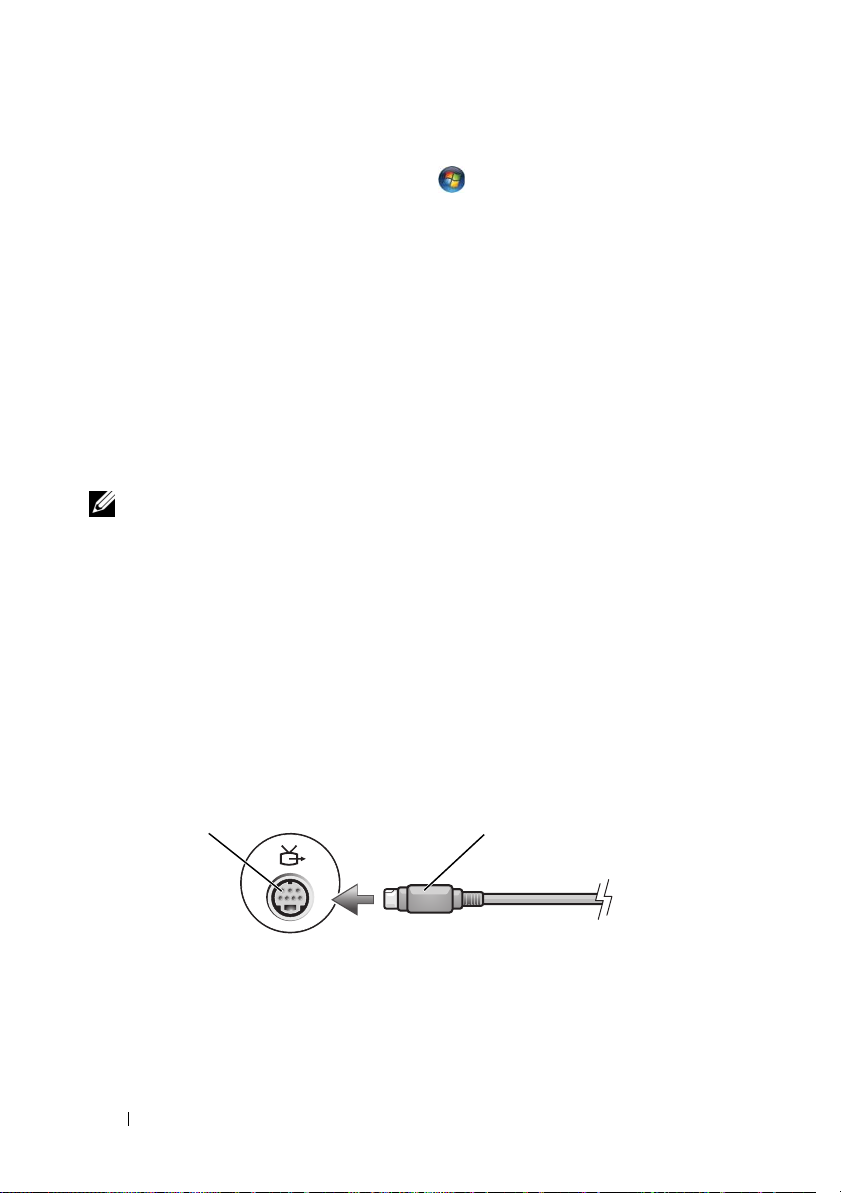
Your computer has an S-video TV-out connector (optional) that, together
with a standard S-video cable, a composite video adapter cable, or a
component video adapter cable (available from Dell), enable you to connect
the computer to a TV.
Your TV has either an S-video input connector, a composite video-input
connector, or a component video-input connector. Depending on what type
of connector is available on your TV, you can use a commercially available
S-video cable, composite video cable, or component video cable to connect
your computer to your TV.
1
1 S-video TV-out connector 2 S-video connector
48 Using Multimedia
2
Page 49
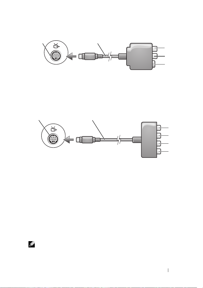
1
1 S-video TV-out connector 2 composite video adapter
3 S/PDIF digital audio connector 4 composite video-output connector
5 S-video connector
12
1 S-video TV-out connector 2 component video adapter
3 S/PDIF digital audio connector 4 Pr (red) component video-output connector
5 Pb (blue) component
video-output connector
2
3
4
5
3
4
5
6
6 Y (green) component video-output
connector
If you want to connect your computer to a TV or audio device, it is
recommended that you connect video and audio cables to your computer in
one of the following combinations.
• S-video and standard audio
• Composite video and standard audio
• Component-out video and standard audio
NOTE: See the diagrams at the beginning of each subsection to help you determine
which method of connection you should use.
Using Multimedia 49
Page 50
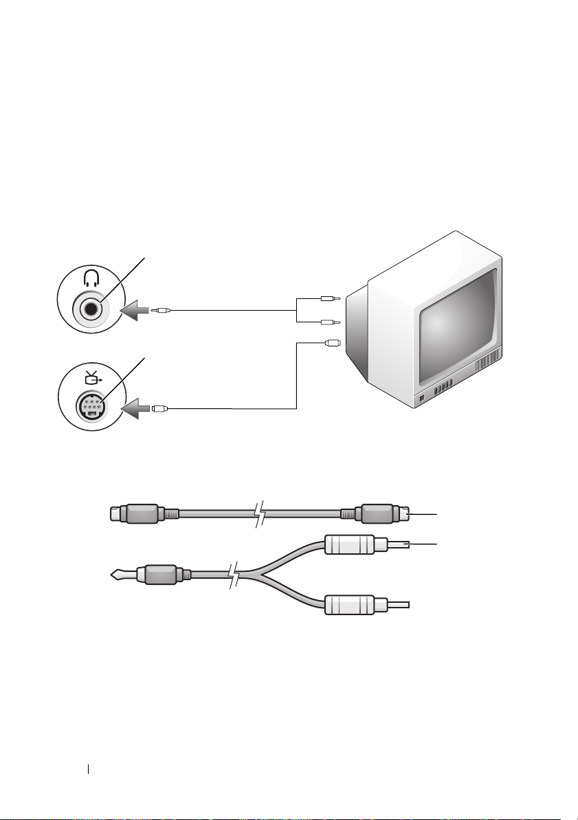
When you finish connecting the video and audio cables between your
computer and your TV, you must enable your computer to work with the TV.
See "Enabling the Display Settings for a TV" on page 63 to ensure that the
computer recognizes and works properly with the TV. Additionally, if you are
using S/PDIF digital audio, see "Enabling S/PDIF Digital Audio" on page 62.
S-Video and Standard Audio
1
2
1 audio connector 2 S-video TV-out connector
1 standard S-video cable 2 standard audio cable
50 Using Multimedia
1
2
Page 51
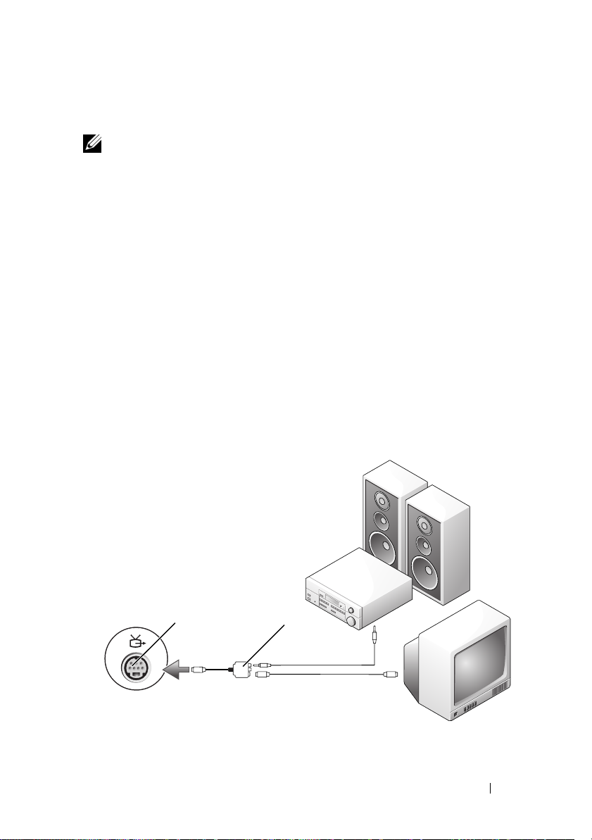
1
Turn off the computer and the TV and/or audio device that you want to
connect.
NOTE: If your TV or audio device supports S-video but not S/PDIF digital audio, you
can connect an S-video cable directly to the S-video TV-out connector on the
computer (without the TV/digital audio adapter cable).
2
Plug one end of the S-video cable into the S-video output connector on
the computer.
3
Plug the other end of the S-video cable into the S-video input connector
on your TV.
4
Plug the single-connector end of the audio cable into the headphone
connector on your computer.
5
Plug the two RCA connectors on the other end of the audio cable into the
audio input connectors on your TV or other audio device.
6
Turn on the TV and any audio device that you connected (if applicable),
and then turn on the computer.
7
See "Enabling the Display Settings for a TV" on page 63 to ensure that the
computer recognizes and works properly with the TV.
S-Video and S/PDIF Digital Audio
1 2
1 S-video TV-out connector 2 composite video adapter
Using Multimedia 51
Page 52
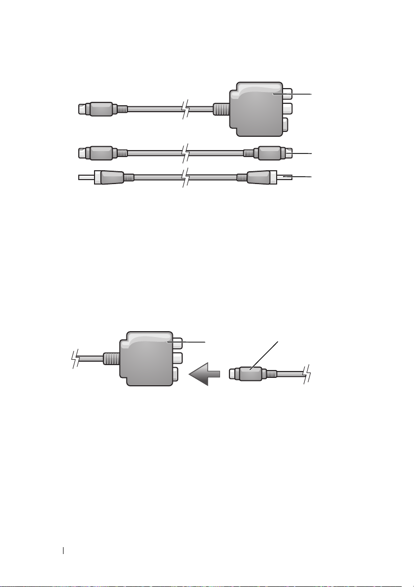
1
2
3
1 composite video adapter 2 S-video cable
3 S/PDIF digital audio cable
1
Turn off the computer and the TV and/or the audio device that you want
to connect.
2
Connect the composite video adapter to the S-video TV-out connector on
your computer.
3
Plug one end of the S-video cable into the S-video output connector on
the composite video adapter.
1
1 composite video adapter 2 S-video cable
4
Plug the other end of the S-video cable into the S-video input connector
2
on the TV.
5
Plug one end of the S/PDIF digital audio cable into the digital audio
connector on the composite video adapter cable.
52 Using Multimedia
Page 53
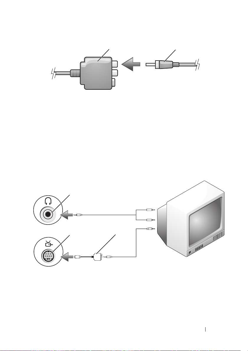
1 2
1 composite video adapter 2 S/PDIF digital audio cable
6
Plug the other end of the S/PDIF digital audio cable into the audio input
connector on your TV or audio device.
7
Turn on the TV, turn on any audio device that you connected
(if applicable), and then turn on the computer.
8
See "Enabling the Display Settings for a TV" on page 63 to ensure that the
computer recognizes and works properly with the TV.
Composite Video and Standard Audio
1
2
1 audio input connector 2 S-video TV-out connector
3 composite video adapter
3
Using Multimedia 53
Page 54
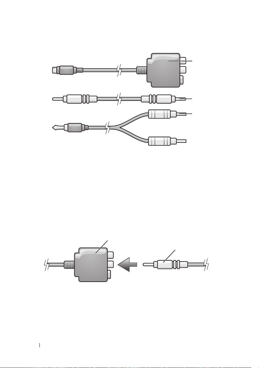
1
2
3
1 composite video adapter 2 composite video cable
3 standard audio cable
1
Turn off the computer and the TV and/or audio device that you want to
connect.
2
Connect the composite video adapter to the S-video TV-out connector on
your computer.
3
Plug one end of the composite video cable into the composite videooutput connector on the composite video adapter.
1
2
1 composite video adapter 2 composite video cable
4
Plug the other end of the composite video cable into the composite videoinput connector on the TV.
54 Using Multimedia
Page 55
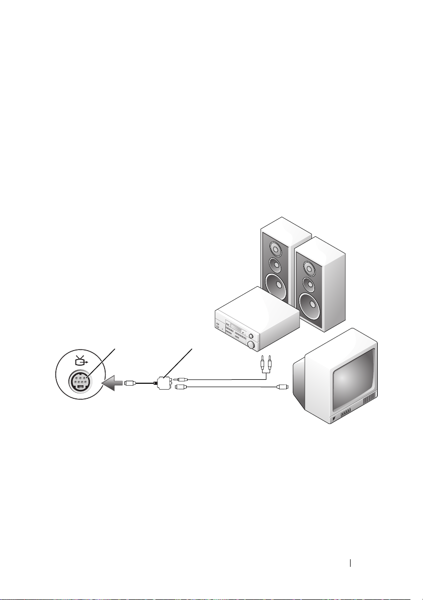
5
Plug the single-connector end of the audio cable into the headphone
connector on the computer.
6
Plug the two RCA connectors on the other end of the audio cable in to the
audio input connectors on your TV or other audio device.
7
Turn on the TV, turn on any audio device that you connected (if
applicable), and then turn on the computer.
8
See "Enabling the Display Settings for a TV" on page 63 to ensure that the
computer recognizes and works properly with the TV.
Composite Video and S/PDIF Digital Audio
1 2
1 S-video TV-out connector 2 composite video adapter
Using Multimedia 55
Page 56
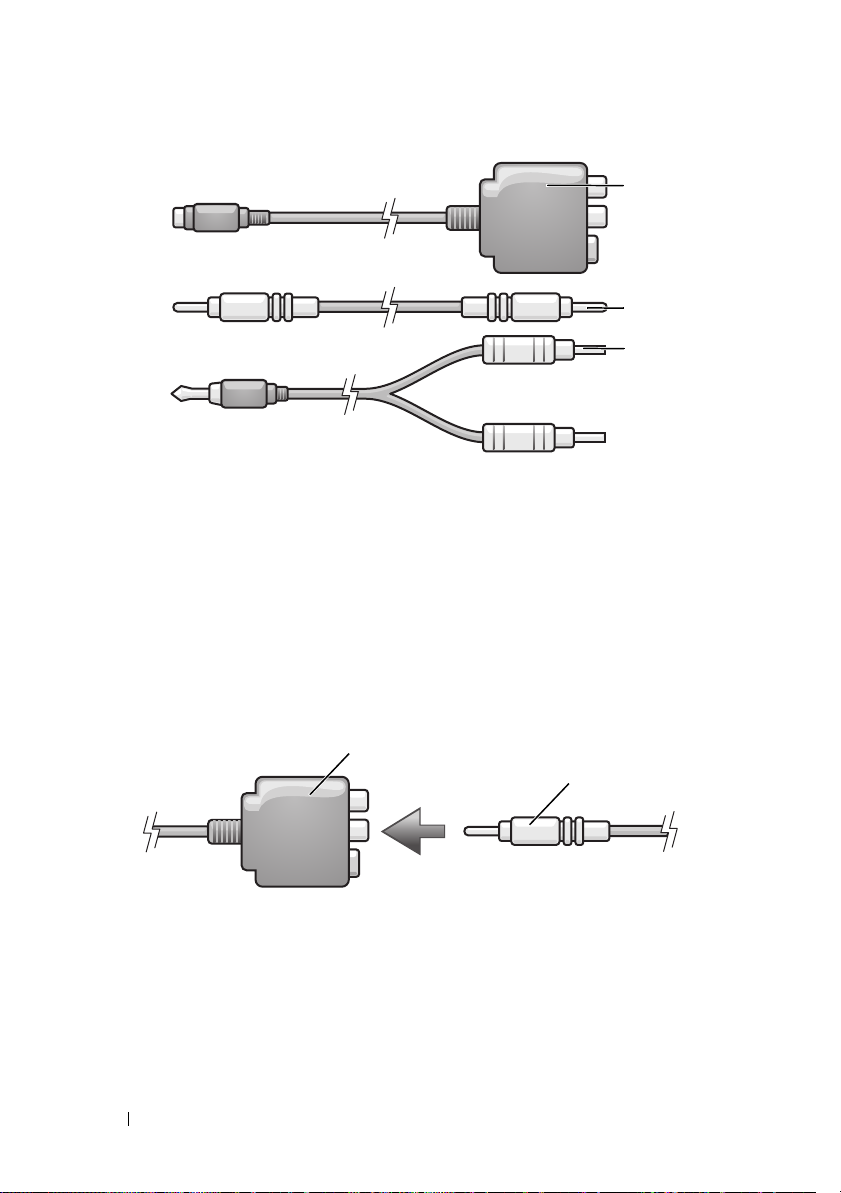
1
2
3
1 composite video adapter 2 composite video cable
3 standard audio cable
1
Turn off the computer and the TV and/or audio device that you want to
connect.
2
Connect the composite video adapter to the S-video TV-out connector on
the computer.
3
Plug one end of the composite video cable into the composite video-input
connector on the composite video adapter.
1
2
1 composite video adapter 2 composite video cable
4
Plug the other end of the composite video cable into the composite
video-input connector on the TV.
5
Plug one end of the S/PDIF digital audio cable in to the S/PDIF audio
connector on the composite video adapter.
56 Using Multimedia
Page 57
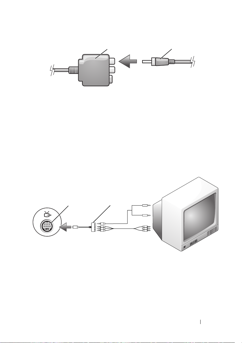
1 2
1 composite video adapter 2 S/PDIF digital audio cable
6
Plug the other end of the digital audio cable into the S/PDIF input
connector on your TV or other audio device.
7
Turn on the TV, turn on any audio device that you connected (if
applicable), and then turn on the computer.
8
See "Enabling the Display Settings for a TV" on page 63 to ensure that the
computer recognizes and works properly with the TV.
Component Video and Standard Audio
1
1 S-video TV-out connector 2 component video adapter
2
Using Multimedia 57
Page 58
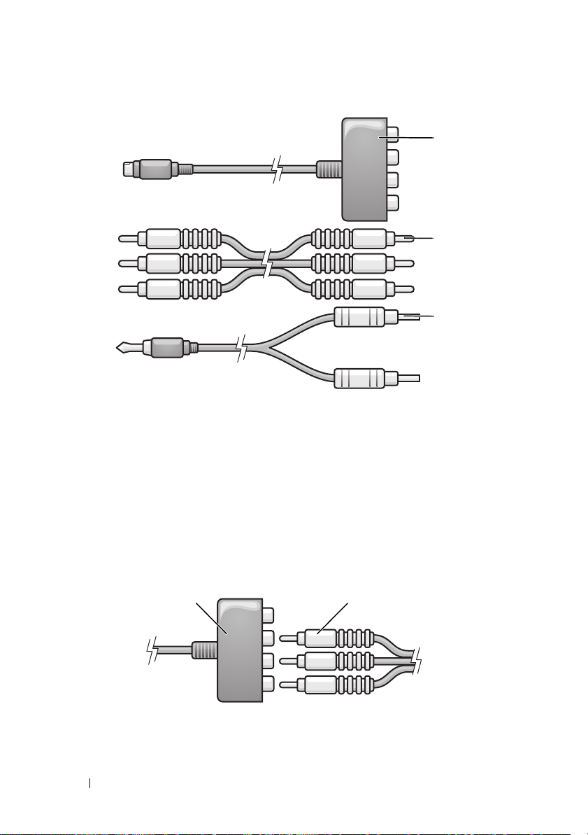
1
2
3
1 component video adapter 2 component video cable
3 standard audio cable
1
Turn off the computer and the TV and/or audio device that you want to connect.
2
Connect the component video adapter to the S-video TV-out connector on
your computer.
3
Plug all three ends of the component video cable into the component videooutput connectors on the component video adapter. Make sure that the red,
green, and blue colors of the cable match the corresponding adapter ports.
1 component video adapter 2 component video cable
58 Using Multimedia
21
Page 59
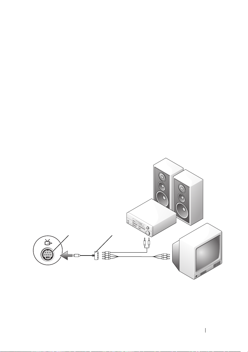
4
Plug all three connectors from the other end of the component video cable
into the component video-input connectors on the TV. Make sure that the
red, green, and blue colors of the cable match the colors of the TV input
connectors.
5
Plug the single-connector end of the audio cable into the headphone
connector on the computer.
6
Plug the two RCA connectors on the other end of the audio cable into the
audio input connectors on your TV or audio device.
7
Turn on the TV, turn on any audio device that you connected (if applicable),
and then turn on the computer.
8
See "Enabling the Display Settings for a TV" on page 63 to ensure that the
computer recognizes and works properly with the TV.
Component Video and S/PDIF Digital Audio
1 2
1 S-video TV-out connector 2 component video adapter
Using Multimedia 59
Page 60
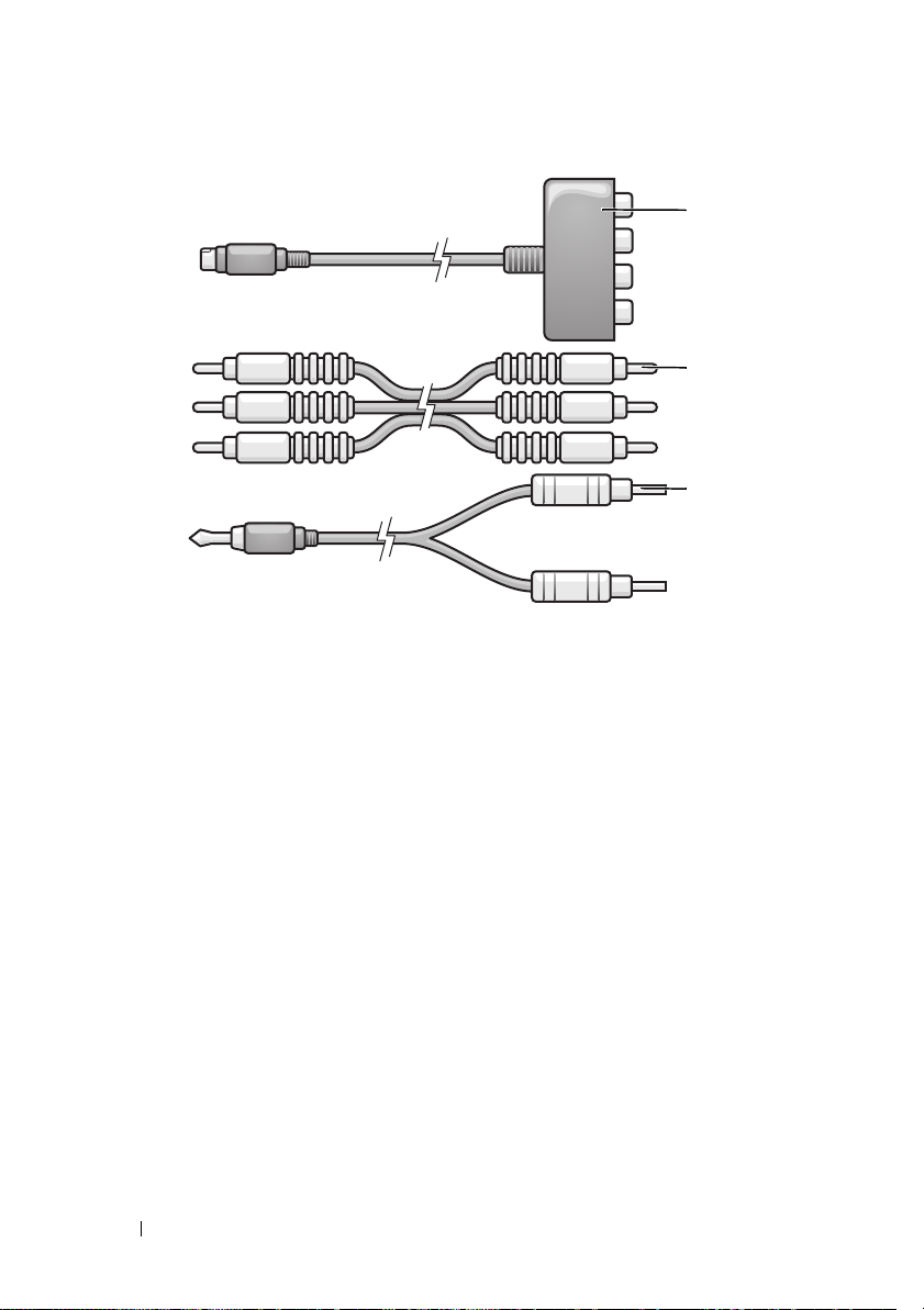
1
2
3
1 component video adapter 2 component video cable
3 standard audio cable
1
Turn off the computer and the TV and/or audio device that you want to
connect.
2
Connect the component video adapter to the S-video TV-out connector on
the computer.
3
Plug all three ends of the component video cable into the component
video-output connectors on the component video adapter. Make sure that
the red, green, and blue colors of the cable match the corresponding
adapter ports.
60 Using Multimedia
Page 61
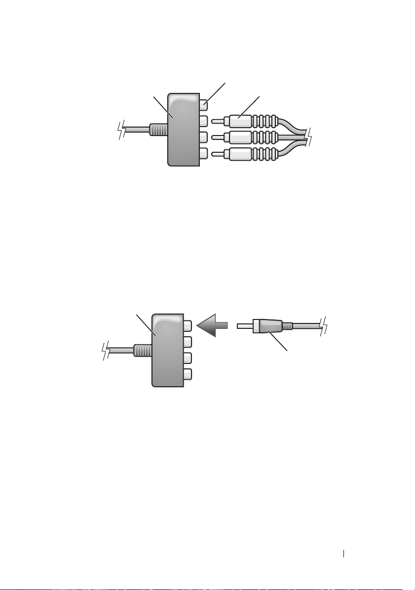
2
31
1 component video adapter 2 component video-output connectors
3 component video cable
4
Plug all three connectors from the other end of the component video cable
into the component video-input connectors on the TV. Make sure that the
red, green, and blue colors of the cable match the colors of the TV input
connectors.
5
Plug one end of the S/PDIF digital audio cable into the S/PDIF audio
connector on the component video adapter.
1
2
1 component video adapter 2 S/PDIF digital audio cable
6
Plug the other end of the digital audio cable into the S/PDIF input
connector on your TV or other audio device.
7
Turn on the TV, turn on any audio device that you connected (if applicable),
and then turn on the computer.
8
See "Enabling the Display Settings for a TV" on page 63 to ensure that the
computer recognizes and works properly with the TV.
Using Multimedia 61
Page 62

Enabling S/PDIF Digital Audio
If your computer has a DVD drive, you can enable digital audio for DVD
playback.
1
Launch the
2
Insert a DVD into the DVD drive.
Cyberlink PowerDVD
application.
If the DVD begins playing, click the stop button.
3
Click the
4
Click the
5
Click the
6
Click the arrows beside the
through the options, and select the
7
Click the
Settings
DVD
DVD Audio Setting
option.
option.
icon.
Speaker Configuration
SPDIF
Back
button once, and then click the
option.
Back
setting to scroll
button again to
return to the main menu screen.
Enabling S/PDIF in the Windows Audio Driver
1
Double-click the speaker icon in the Windows notification area.
2
Click the
3
Click
4
Click
5
Click
6
Click OK.
Options
Advanced
menu and then click
.
S/PDIF Interface
Close
.
Advanced Controls
.
.
Setting Up the Cyberlink (CL) Headphones
NOTE: The CL headphone feature is available only if your computer has a
DVD drive.
If your computer has a DVD drive, you can enable digital audio for DVD
playback.
1
Launch the
2
Insert a DVD into the DVD drive.
If the DVD begins playing, click the stop button.
3
Click the
62 Using Multimedia
Cyberlink PowerDVD
Settings
option.
program.
Page 63

4
Click the
5
Click the
6
Click the arrows beside the
through the options, and select the
7
Click the arrows beside the
the options, and select the
8
Click the arrows beside the
DVD
option.
DVD Audio Setting
Speaker Configuration
Audio listening mode
CL Headphone
Dynamic range compression
icon.
Headphones
setting to scroll
option.
setting to scroll through
option.
option to select
the most suitable option.
9
Click the
Back
button once, and then click the
Back
button again to
return to the main menu screen.
Enabling the Display Settings for a TV
NOTE: To ensure that the display options appear correctly, connect the TV to the
computer before you enable the display settings.
Microsoft Windows XP
Click the
1
2
Double-click
3
Click
4
Click the tab for your video card.
NOTE: To determine the type of video card installed in your computer, see the
Windows Help and Support Center. To access the Help and Support Center, click
Start
information and diagnose problems. Then, under My Computer Information, select
Hardware.
5
In the display devices section, select the appropriate option for using
either a single display or multiple displays, ensuring that the display
settings are correct for your selection.
Windows Vista
1
Click the Windows Vista Start button , click
click
2
Under
The
Start
Display
Advanced
button, point to
and click the
.
Settings
Settings
, and then click
tab.
Control Panel
→ Help and Support. Under Pick a Task, click Use Tools to view your computer
Control Panel
Appearance and Personalization
Personalization
Display Properties
, click
Adjust Screen Resolution
window appears.
.
.
.
, and then
3
Click
Advanced
.
Using Multimedia 63
Page 64

4
Click the tab for your video card.
NOTE: To determine the type of video card installed in your computer, see the
Windows Help and Support Center. To access the Help and Support Center in
→
Windows Vista, click the Windows Vista Start button
Under Pick a Task, click Use Tools to view your computer information and diagnose
problems. Then, under My Computer Information, select Hardware.
5
In the display devices section, select the appropriate option for using
Help and Support.
either a single display or multiple displays, ensuring that the display
settings are correct for your selection.
Using a Media Card Reader (Optional)
CAUTION: Before you perform any of the procedures in this section, follow the
safety instructions in the Product Information Guide.
Use the media card reader to transfer data directly to your computer.
The media card reader can also be used to pair Bluetooth
computer.
The media card reader supports the following memory types:
• xD-Picture card
• SmartMedia card (SMC)
• CompactFlash card Type I and II (CF I/II)
• MicroDrive card
• SecureDigital card (SD)
• MiniSD card
• MultiMediaCard (MMC)
• Reduced-size MultiMediaCard (RS-MMC)
• Memory Stick (MS/MS Pro/MS Duo/MS Pro Duo)
For information on installing a media card reader, see "Installing a Media
Card Reader" in the Service Manual on the Dell Support website at
support.dell.com.
®
devices with the
64 Using Multimedia
Page 65
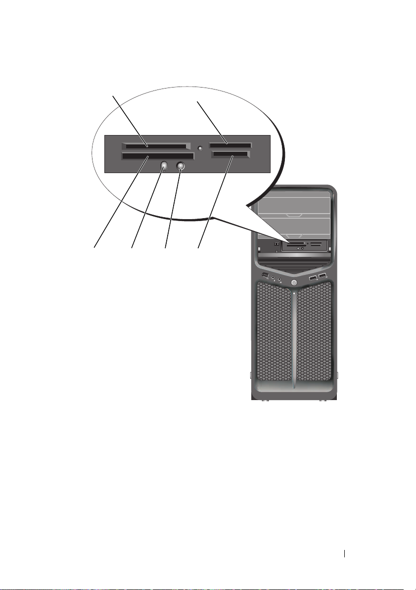
1
2
6
1 xD-Picture card and
SmartMedia Card
(SMC)
4 Bluetooth pairing
button
5
4
2 Memory Stick
5 Bluetooth LED 6 CompactFlash card Type I and
3
(MS/MS Pro/MS
Duo/MS Pro Duo)
3 Secure Digital card
(SD/miniSD)/MultiMedia-Card
(MMC/RS-MMC)
II (CF I/II) and MicroDrive card
Using Multimedia 65
Page 66

1
Inspect the media card to determine the proper orientation for insertion.
2
Slide the media card into the appropriate slot of the media card reader
until it is completely seated in the connector.
3 If you encounter resistance, remove the card, check for proper
orientation, and then try again.
Instructions for Setting Up a Device With Bluetooth Wireless Technology
1
Turn on the device.
2
Press the connect button on the device.
The Bluetooth LED on the device blinks, indicating that the device is
active and can be detected by the computer.
3
Press the connect button on the front of the media card reader.
4
The Bluetooth LED on the device stops blinking and stays on for a few
moments indicating that the connection between the device and the
computer has been established. The LED then turns off.
66 Using Multimedia
Page 67

About RAID Configurations
NOTICE: In order to use the migrating option to convert a RAID configuration
without losing data, your hard drive must initially be set up as a single drive RAID 0
array before the operating system is loaded onto the drive (see "Using the Nvidia
MediaShield ROM Utility" on page 70 for instructions).
This section provides an overview of the RAID configuration you may have
selected when you purchased your computer. There are several RAID
configurations available in the computer industry for different types of uses.
Your computer supports RAID level 0 and RAID level 1. A RAID level 0
configuration is recommended for high-performance programs, while RAID
level 1 is recommended for users that desire a high level of data integrity.
NOTE: RAID levels do not represent a hierarchy. A RAID level 1 configuration is not
inherently better or worse than a RAID level 0 configuration.
The drives in a RAID configuration should be the same size in order to ensure
that the larger drive does not contain unallocated (and therefore unusable) space.
RAID level 0 and RAID level 1 require a minimum of two drives.
RAID Level 0 Configuration
NOTICE: Because a RAID level 0 configuration provides no data redundancy, a
failure of one drive results in the loss of all data. To protect your data when using a
RAID level 0 configuration, perform regular backups.
RAID level 0 uses a storage technique known as data striping to provide a
high data access rate. Data striping is a method of writing consecutive
segments, or stripes, of data sequentially across the physical drive(s) to create
a large virtual drive. Data striping allows one of the drives to read data while
the other drive is searching for and reading the next block.
About RAID Configurations 67
Page 68
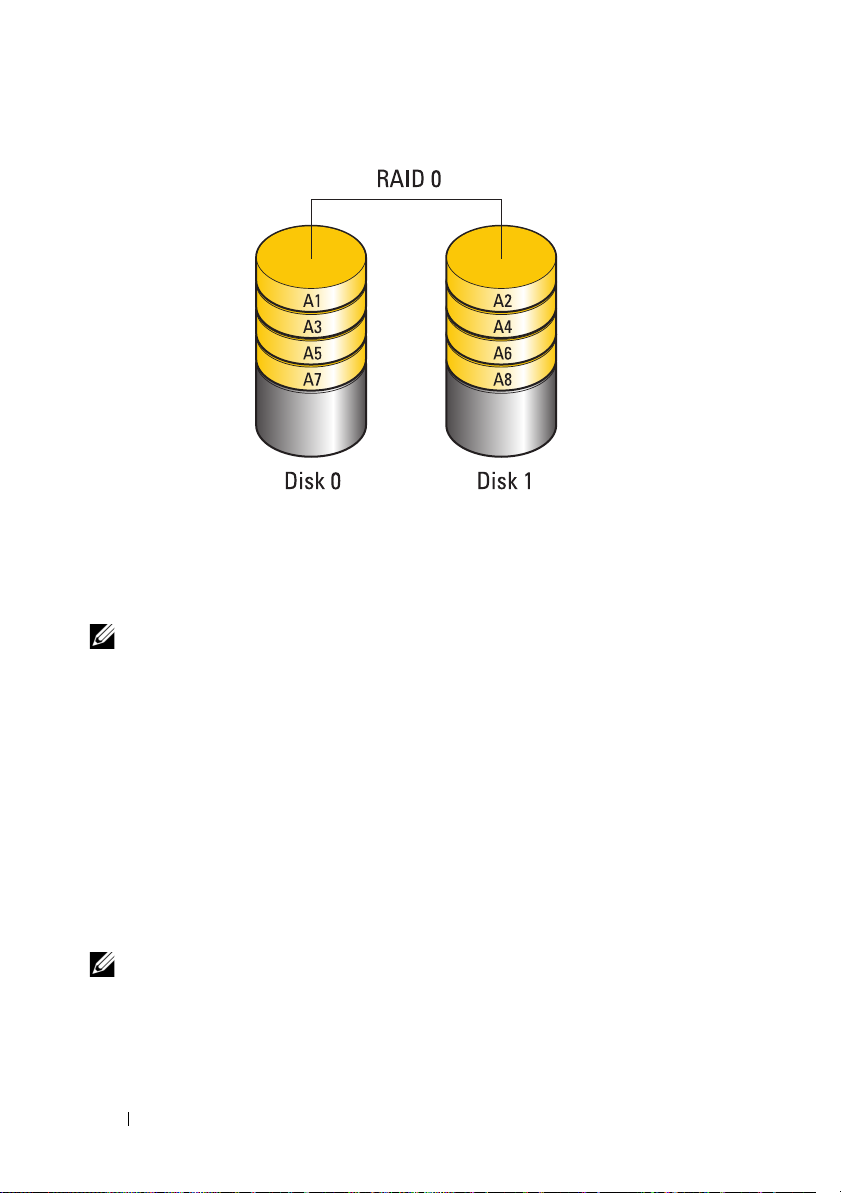
Another advantage of a RAID level 0 configuration is that it utilizes the full
storage capacities of the drives. For example, two 120-GB hard drives
combine to provide 240 GB of hard drive space on which to store data.
NOTE: In a RAID level 0 configuration, the size of the configuration is equal to the
size of the smallest drive multiplied by the number of drives in the configuration.
RAID Level 1 Configuration
RAID level 1 uses a data-redundancy storage technique known as mirroring to
enhance data integrity. When data is written to the primary drive, the data is
also duplicated, or mirrored, on the second drive in the configuration. A
RAID level 1 configuration sacrifices high data-access rates for its data
redundancy advantages.
If a drive failure occurs, subsequent read and write operations are directed to
the surviving drive. A replacement drive can then be rebuilt using the data
from the surviving drive.
NOTE: In a RAID level 1 configuration, the size of the configuration is equal to the
size of the smallest drive in the configuration.
68 About RAID Configurations
Page 69
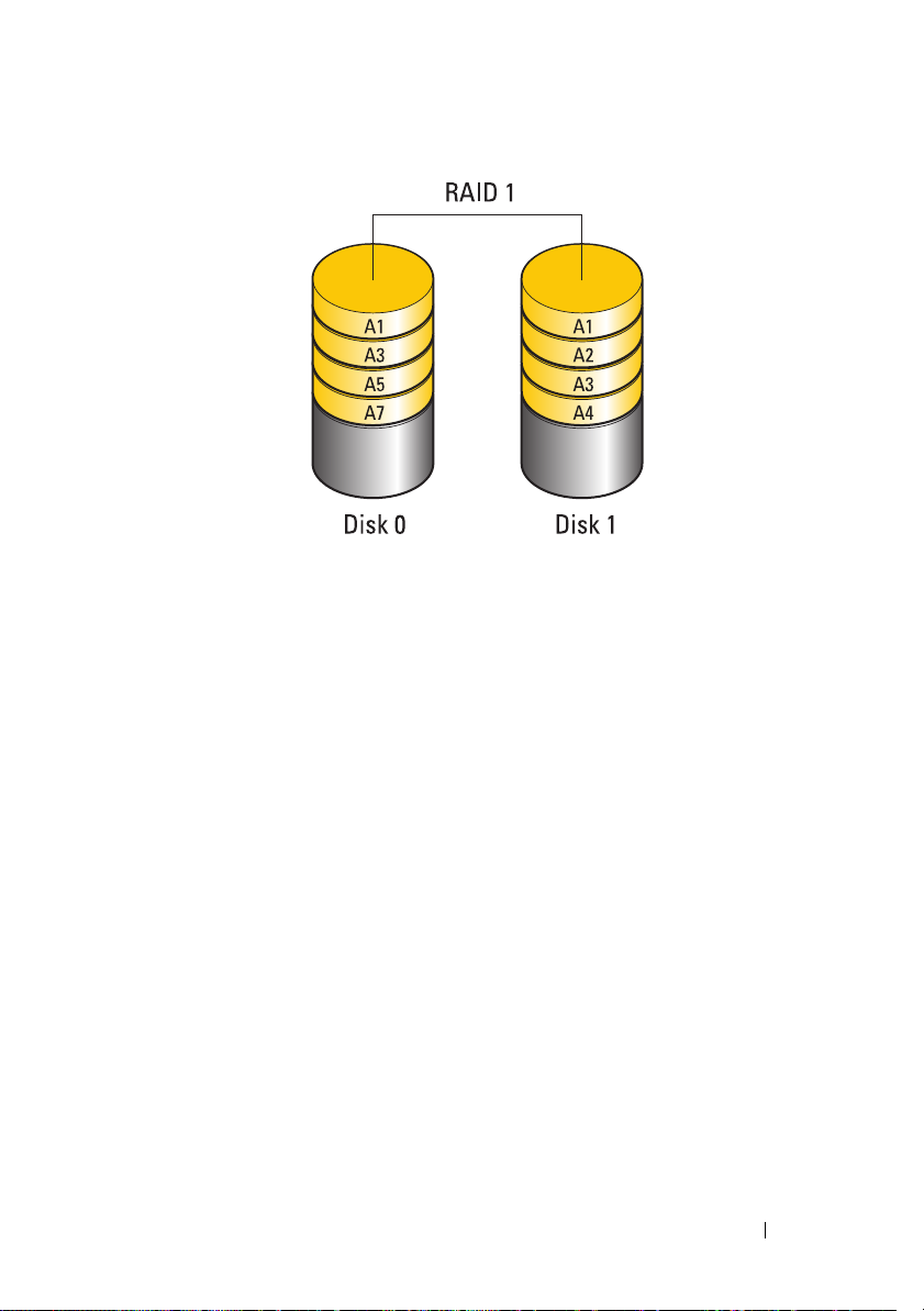
Configuring Your Hard Drives for RAID
Your computer can be configured for RAID, even if you did not select a RAID
configuration when the computer was purchased. For an explanation of RAID
levels and their requirements, see "About RAID Configurations" on page 67.
For information on how to install a hard drive, see "Installing a Hard Drive" in
the Service Manual on the Dell Support website at support.dell.com.
You can use one of two methods to configure RAID hard drive volumes.
The first method uses the Nvidia MediaShield ROM utility and is performed
before you install the operating system onto the hard drive. The second
method uses Nvidia MediaShield and is performed after you have installed
the operating system and Nvidia RAID drivers.
Both methods require that you set your computer to RAID-enabled mode
before you begin.
Setting Your Computer to RAID-Enabled Mode
1
Enter system setup (see "Entering System Setup" on page 77).
2
Press the up- and down-arrow keys to highlight
Drives
, then press <Enter>.
About RAID Configurations 69
Page 70

3
Press the up- and down-arrow keys to highlight the applicable SATA drive,
then press <Enter>.
4
Press the left- and right-arrow keys to highlight
RAID On
, and then press
<Enter>. Repeat the process, as needed, for each SATA hard drive.
NOTE: For more information about RAID options, see "System Setup Options"
on page 79.
5
Press <Esc>, press the left- and right-arrow keys to highlight
Save/Exit
,
and then press <Enter> to exit system setup and resume the boot process.
Using the Nvidia MediaShield ROM Utility
NOTICE: The following procedure will result in the loss of all data on your hard
drive(s). Back up any data you want to keep before continuing.
NOTE: Do not use the following procedure to migrate an existing RAID
configuration (see "Converting From One RAID Configuration to Another RAID
Configuration" on page 73).
Hard drives of any size may be used to create a RAID configuration. Ideally,
however, the drives should be of equal size to avoid unallocated or unused
space. For an explanation of RAID levels and their requirements, see "About
RAID Configurations" on page 67. For information on how to install a hard
drive, see "Installing a Hard Drive" in the Service Manual on the Dell Support
website at support.dell.com.
1
Enable RAID for each applicable hard drive on your computer (see
"Setting Your Computer to RAID-Enabled Mode" on page 69).
2
Restart the computer.
3
Press <Ctrl><N> when prompted to enter the RAID BIOS.
NOTE: If the operating system logo appears, continue to wait until you see the
Microsoft Windows desktop, then shut down your computer and try again.
The
Define a New Array
4
Press <Tab> to navigate to the
window appears.
RAID Mode
field.
To create a RAID 0 configuration, use the arrow keys to select
To create a RAID 1 configuration, use the arrow keys to select
5
Press <Tab> to navigate to the
Free Disks
field.
70 About RAID Configurations
Striping
Mirroring
.
.
Page 71

6
Use the up- and down-arrow keys to select a hard drive to include in the
RAID array and then use the right-arrow key to move the selected drive
from the
Free Disks
field to the
Array Disks
field. Repeat for each disk you
want to include in the RAID array.
NOTE: Your computer supports a maximum of two drives per RAID 1 array and
four drives per RAID 0 array.
7
After assigning the hard drives to an array, press <F9>.
Clear disk data
The
NOTICE: You will lose all data on the selected drives in the next step.
8
Press <Y> to clear all data from the selected drives.
Array List
The
9
To review the details of the array that you set up, use the arrow keys to
highlight the array in the
The
Array Detail
NOTE: To delete an array, use the arrow keys to select the array and press <D>.
10
Press <Enter> to return to the previous screen.
11
Press <Ctrl><X> to exit the RAID BIOS.
prompt appears.
window appears.
Array Detail
window appears.
window and press <Enter>.
Using Nvidia MediaShield
Nvidia MediaShield allows you to create, view, and manage RAID configurations.
NOTE: Use Nvidia MediaShield to create a RAID configuration only when you are
adding one or more new hard drives to an existing (non-RAID) single-drive
computer, and you want to configure the new drive(s) into a RAID array.
Hard drives of any size may be used to create a RAID configuration using
Nvidia MediaShield. Ideally, however, the drives should be of equal size to
avoid unallocated or unused space. For an explanation of RAID levels and
their requirements, see "About RAID Configurations" on page 67.
Creating a RAID Array
NOTICE: The following procedure will result in the loss of all data on your hard drive(s).
Back up any data you want to keep before continuing.
NOTE: Do not use the following procedure to migrate an existing RAID configuration (see
"Converting From One RAID Configuration to Another RAID Configuration" on page 73).
About RAID Configurations 71
Page 72

1
Enable RAID on your hard drives (see "Setting Your Computer to RAIDEnabled Mode" on page 69).
2
After rebooting your computer, launch Nvidia MediaShield.
3
Click
Create
under
System Tasks
The
NVIDIA Create Array Wizard
.
appears and lists the disks that are
available for configuration.
4
Click
Next
.
5
Click
Custom
6
Use the drop-down box to select
7
Click
Next
The
Free Disk Selection
NOTE: Only RAID-enabled hard drives are listed as free disks.
8
Click to select the drives that will make up the RAID configuration, click
Next
, and then click
NOTE: Your computer supports a maximum of two drives per RAID 1 array and
four per RAID 0 array.
The
Clearing System Data
NOTICE: The Clear System Data option deletes all data on the selected drive.
9
Click
Next
10
Click
Finish
, then click
Next
.
Striping
(RAID 0) or
.
window appears.
Next
again.
window appears.
.
to create the RAID configuration.
Mirroring
(RAID 1).
The MediaShield RAID management utility window appears and lists the
array along with any other installed hard drives.
Deleting a RAID Array
NOTE: While this procedure deletes the RAID 1 volume, it also splits the RAID 1
volume into two non-RAID hard drives with a partition, and leaves any existing data
files intact. Deleting a RAID 0 volume, however, destroys all data on the volume.
NOTE: If your computer currently boots to RAID and you delete the RAID volume,
your computer will become unbootable.
1
Launch Nvidia MediaShield.
2
Click to select the array you want to delete.
72 About RAID Configurations
Page 73

3
Click
4
Delete Array
The
NVIDIA Delete Array Wizard
Click
Next
.
in the
System Tasks
pane.
appears.
A confirmation screen appears with the name and size of the array that you
have marked for deletion.
5
Click
Finish
to delete the RAID configuration.
The MediaShield RAID management utility window appears and lists any
remaining arrays along with any other installed hard drives.
Converting From One RAID Configuration to Another RAID Configuration
NOTICE: In order to use the migrating option to convert a RAID configuration
without losing data, your hard drive must initially be set up as a single drive RAID 0
array before the operating system is loaded onto the drive (see "Using the Nvidia
MediaShield ROM Utility" on page 70 for instructions).
Nvidia MediaShield utilizes a one-step process known as migrating to change
the current state of a disk or array without losing any data. If needed,
additional hard drives can be added to an existing array, including a single-drive
RAID 0 configuration for conversion to a two-drive RAID 0 configuration;
however, the capacity of the resulting array must be equal to or greater than
the size of the original configuration.
RAID 0 to RAID 1
conversions cannot be performed using the migrating process.
NOTICE: Additional hard drives to be used in the (migrated) array must be no
smaller than any of the drives in the current configuration.
NOTE: Ensure that all drives to be used in the RAID configuration are
RAID-enabled (see "Setting Your Computer to RAID-Enabled Mode" on page 69).
1
Launch Nvidia MediaShield.
2
Click to select the array you want to convert.
3
Click
4
Convert Array
The
NVIDIA Convert Array Wizard
Click
Next
.
in the
System Tasks
appears.
About RAID Configurations 73
pane.
Page 74

5
Under
RAID Mode Selection
, select
Mirroring or Striping
from the
drop-down menu.
6
Click
Next
.
NOTICE: You will lose all data on the selected drives in the next step.
7
Under
Free Disk Selection
, select the hard drive(s) you want to include in
the (migrated) array by clicking the checkbox beside it.
8
Click
Finish
.
The MediaShield RAID management utility window appears and displays
the status of the upgrade/migration process along with any other installed
hard drives.
NOTE: The time it takes to convert an array depends on several factors, such
as the speed of the CPU, the type and size of the hard drive being used, the
operating system, etc.
Rebuilding a RAID Configuration
If one of the hard drives in a RAID array fails, you can rebuild the array by
restoring the data to a replacement drive.
NOTE: Rebuilding an array can only be performed on RAID 1 configuration.
1
Launch Nvidia MediaShield.
2
Click to select your RAID configuration (
utility window.
3
Select
Rebuild Array
NVIDIA Rebuild Array Wizard
The
in the
System Tasks
Mirroring
pane.
appears.
) in the management
4
Click
Next
.
5
Select the hard drive you want to rebuild by clicking the checkbox beside it.
6
Click
Next
.
7
Click
Finish
.
The MediaShield RAID management utility window appears and displays
the status of the rebuild process.
NOTE: You can use your computer while the computer is rebuilding the array.
NOTE: You can use any available (RAID-enabled) free disk to rebuild an array.
74 About RAID Configurations
Page 75
Cleaning Your Computer
CAUTION: Before you begin any of the procedures in this section, follow the
safety instructions in the Product Information Guide.
Computer, Keyboard, and Monitor
CAUTION: Before you clean your computer, disconnect the computer from the
electrical outlet. Clean your computer with a soft cloth dampened with water. Do
not use liquid or aerosol cleaners, which may contain flammable substances.
• Use a vacuum cleaner with a brush attachment or a can of compressed air
to remove dust from the slots and holes on your computer and from
between the keys on the keyboard.
NOTICE: Do not wipe the display screen with a soap or alcohol solution. Doing so
may damage the antiglare coating.
• To clean your monitor screen, lightly dampen a soft, clean cloth with water.
If possible, use a screen-cleaning tissue or solution suitable for the
monitor’s antistatic coating.
NOTICE: Do not soak the cloth or let water drip inside your computer or keyboard.
• Wipe the keyboard, computer, and plastic part of the monitor with a soft
cleaning cloth moistened with water.
Mouse (Non-Optical)
1
Turn the retainer ring on the underside of your mouse counterclockwise,
and then remove the ball.
2
Wipe the ball with a clean, lint-free cloth.
3
Blow carefully into the ball cage to dislodge dust and lint.
4
Clean the rollers inside the ball cage with a cotton swab moistened lightly
with isopropyl alcohol.
Cleaning Your Computer 75
Page 76

5
Recenter the rollers in their channels, as needed. Ensure that fluff from
the swab is not left on the rollers.
6
Replace the ball and retainer ring, and then turn the retainer ring clockwise
until it clicks into place.
Floppy Drive
NOTICE: Do not attempt to clean drive heads with a swab. You might accidentally
misalign the heads which prevents the drive from operating.
Clean your floppy drive using a commercially available cleaning kit. These
kits contain pretreated floppy disks to remove contaminants that accumulate
during normal operation.
CDs and DVDs
NOTICE: Always use compressed air to clean the lens in the CD/DVD drive, and
follow the instructions that come with the compressed-air product. Never touch the
lens in the drive.
If you notice problems, such as skipping, with the playback quality of your
CDs or DVDs, try cleaning the discs.
1
Hold the disc by its outer edge. You can also touch the inside edge of the
center hole.
NOTICE: To avoid damaging the surface, do not wipe in a circular motion around
the disc.
2
With a soft, lint-free cloth, gently wipe the bottom of the disc (the
unlabeled side) in a straight line from the center to the outer edge of the
disc.
For stubborn dirt, try using water or a diluted solution of water and mild
soap. You can also purchase commercial products that clean discs and
provide some protection from dust, fingerprints, and scratches. Cleaning
products for CDs are also safe to use on DVDs.
76 Cleaning Your Computer
Page 77

System Setup
Overview
Use System Setup:
• To change the system configuration information after you add, change, or
remove any hardware in your computer.
• To set or change a user-selectable option such as the user password.
• To read the current amount of memory or set the type of hard drive installed.
Before you use System Setup, it is recommended that you write down the
system setup screen information for future reference.
NOTICE: Do not change the settings in system setup unless you are an expert
computer user. Certain changes can cause your computer to work incorrectly.
Entering System Setup
1
Turn on (or restart) your computer.
2
When the DELL logo appears, press <F2> immediately.
NOTE: Keyboard failure may result when a key on the keyboard is held down
for extended periods of time. To avoid possible keyboard failure, press and
release <F2> in even intervals until the system setup screen appears.
If you wait too long and the operating system logo appears, continue to
wait until you see the Microsoft
your computer and try again.
®
Windows® desktop, then shut down
System Setup Screens
The System Setup screen displays current or changeable configuration
information for your computer. Information on the screen is divided into five
areas: the menu field, the options list, the active options field, the help field,
and key functions.
System Setup 77
Page 78
Menu — Appears on top of the System Setup window. This field provides a
menu to access to the System Setup options. Press <>and< >keys to
navigate. As a Menu option is highlighted, the Options List, lists the
options that define the hardware installed on you computer.
Options List —
Appears on the left side
of the System Setup
window. The field lists
features that define the
configuration of your
computer, including
installed hardware,
power conservation, and
security features.
Scroll up and down the
list with the up- and
down-arrow keys. As an
option is highlighted,
the Options Field
displays the option’s
current and available
settings.
Options Field —
Appears on the right side
of Options List and
contains information
about each option listed
in the Options List. In
this field you can view
information about your
computer and make
changes to your current
settings.
Press <Enter> to make
changes to your current
settings. Press <ESC>
to return to the Options
List.
NOTE:
Not all settings listed
in the Options Field are
changeable.
Help — Appears on
the right side of the
System Setup
window and contains
help information
about the option
selected in Options
List.
Key Functions — Appears below the Options Field and lists keys and their
functions within the active system setup field.
78 System Setup
Page 79
System Setup Options
NOTE: Depending on your computer and installed devices, the items listed in this
section may not appear, or may not appear exactly as listed.
Main
System Info Displays the system model name.
BIOS Info Display the BIOS revision.
Service Tag Displays the system service tag.
Express Service Code Displays the express service code.
Asset Tag Displays the asset tag.
Date Displays the system date.
Time Displays the system time.
Memory Installed Displays the total memory size.
Memory Available Displays the memory available in the system.
Memory Speed Displays the memory speed.
Memory Channel Mode Displays the memory channel modes.
•Single
•Dual
Memory Technology Displays the type of memory used in the system.
Processor Type Displays the type of processor.
Processor Speed Displays the speed of the processor.
Processor L2 cache Displays the processor L2 cache size.
System Setup 79
Page 80

Advanced
CPU Feature Allows you to enable or disable the CPU features that enhance
the performance of the system.
Integrated
Peripherals
IDE/SATA
Configuration
Overclock
Configuration
Overvoltage
configuration
Security
Supervisor
Password Is
User Password IsSpecifies whether a user password has been assigned.
Allows you to enable or disable the integrated devices and ports
on your system.
Enables or disables a user to define or change any values related
to IDE or SATA devices such as hard drives, optical drives, and
so on connected to the computer.
This option enables you to set the system clock mode.
This option enables you to configure the voltage of the CPU
core, FSB, memory voltage, and chipset voltage.
Specifies whether a supervisor password has been assigned.
Set Supervisor
Password
Set User
Password
80 System Setup
Allows you to set a supervisor password.
Allows you to set a user password. You cannot use the user
password to enter the BIOS setup, during POST.
Page 81

Power
ACPI Suspend
Type
AC Recovery Specifies the behaviour of the system after recovering from a
Remote Wake Up This option turns on the computer when a user tries to access
Wake-Up By
Ring
Auto Power On Enables you to set an alarm to turn on the computer
Boot
Removable
Device
Priority
Hard Disk Boot
Priority
1st Boot Device
through 3rd Boot
Device
Boot Other
Device
Specifies the ACPI suspend type. The default is S3.
power loss.
• On — The computer turns on after it recovers from a power
failure.
• Off — The computer remains powered off.
• Last — The computer returns the power state it was in
before the power failure.
the computer through the LAN.
This option turns on the computer when an incoming call is
detected on the modem.
automatically.
Sets the boot priority among the attached removable devices.
Sets the hard drive boot priority. The items displayed are
dynamically updated according to the hard drives detected.
Sets the boot device sequence. Only the bootable devices that
are connected to the computer are listed as options.
This option enables you to boot from other devices such as a
memory key.
Exit
Exit Options Provides options to Exit Saving Changes, Exit Discarding
Changes, Load Setup Default, and Discard Changes.
System Setup 81
Page 82

Boot Sequence
This feature allows you to change the boot sequence for the bootable devices
installed on your computer.
Option Settings
•
Diskette Drive —
If the floppy disk in the drive is not bootable, if no floppy disk is in the drive,
or if there is no floppy drive installed in the computer, the computer attempts
to boot from the next bootable device in the boot sequence.
•
Hard Drive
drive. If no operating system is on the drive, the computer attempts to
boot from the next bootable device in the boot sequence.
CD Drive
•
is in the drive, or if the CD has no operating system, the computer
attempts to boot from the next bootable device in the boot sequence.
•
USB Flash Device —
restart the computer. When
corner of the screen, press <F12>. The BIOS detects the device and adds
the USB flash option to the boot menu.
NOTE: To boot to a USB device, the device must be bootable. To ensure that your
device is bootable, check the device documentation.
NOTE: An error message is generated only after the computer attempts to boot
from every device in the boot sequence and no operating system is found.
— The computer attempts to boot from the CD drive. If no CD
The computer attempts to boot from the floppy drive.
— The computer attempts to boot from the primary hard
Insert the memory device into a USB port and
F12 = Boot Menu
appears in the upper-right
Changing Boot Sequence for the Current Boot
You can use this feature, for example, to tell the computer to boot from the
CD drive so that you can run the Dell Diagnostics on the Driver and Utilities
media, but you want the computer to boot from the hard drive when the
diagnostic tests are complete. You can also use this feature to restart your
computer to a USB device such as a floppy drive, memory key, or CD-RW drive.
NOTE: If you are booting to a USB floppy drive, you must first set the floppy drive to
OFF in system setup (see "System Setup" on page 77).
1
If you are booting to a USB device, connect the USB device to a USB
connector (see "Back View of the Computer" on page 19).
2
Turn on (or restart) your computer.
82 System Setup
Page 83

3
When the DELL logo appears, press <F12> immediately.
NOTE: Keyboard failure may result when a key on the keyboard is held down
for an extended period of time. To avoid possible keyboard failure, press and
release <F12> in even intervals until the Boot Device Menu appears.
If you wait too long and the operating system logo appears, continue to
wait until you see the Microsoft Windows desktop, then shut down your
computer and try again.
4
At the
Boot Device Menu
, use the up- and down-arrow keys or press the
appropriate number on the keyboard to highlight the device that is to be
used for the current boot only, and then press <Enter>.
For example, if you are booting to a USB memory key, highlight
Device
and press <Enter>.
NOTE: To boot to a USB device, the device must be bootable. To ensure that your
device is bootable, check the device documentation.
USB Flash
Changing Boot Sequence for Future Boots
1
Enter system setup (see "Entering System Setup" on page 77).
2
Use the arrow keys to highlight the
<Enter> to access the menu.
NOTE: Write down your current boot sequence in case you want to restore it.
3
Press the up- and down-arrow keys to move through the list of devices.
4
Press the spacebar to enable or disable a device.
5
Press plus (+) or minus (–) to move a selected device up or down the list.
Boot Sequence
menu option and press
System Setup 83
Page 84

84 System Setup
Page 85
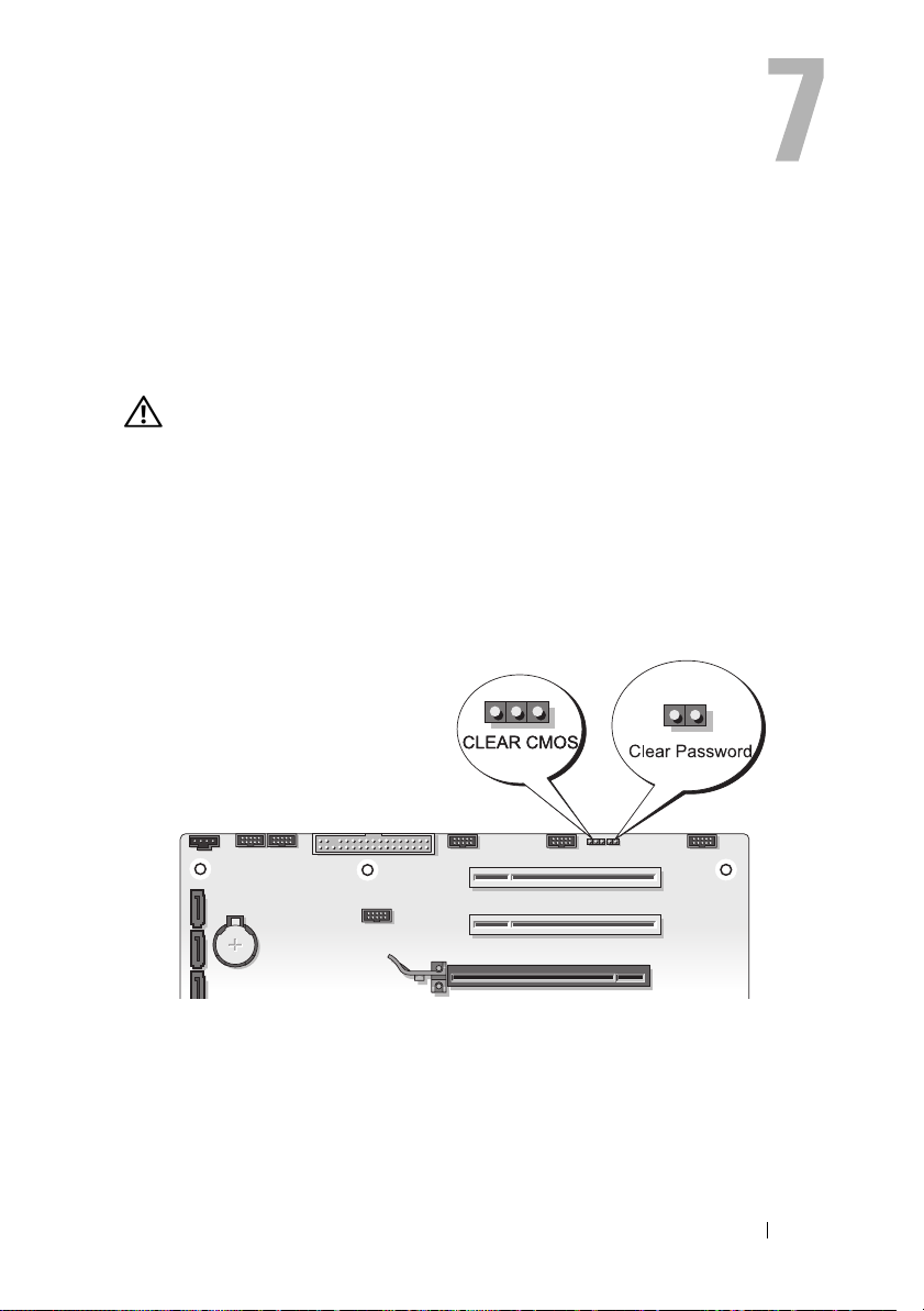
Clearing Passwords and CMOS Settings
Clearing Passwords
CAUTION: Before you begin any of the procedures in this section, follow the
safety instructions located in the Product Information Guide.
1
Follow the procedures in "Before You Begin" in the
Dell Support website at
2
Remove the computer cover (see "Removing the Computer Cover" in the
Service Manual
3
Locate the 2-pin password connector on the system board.
on the Dell Support website at
support.dell.com
.
Service Manual
support.dell.com
on the
).
4
Remove the 2-pin jumper plug from the pins and set the jumper plug
aside.
Clearing Passwords and CMOS Settings 85
Page 86

5
Replace the computer cover (see "Replacing the Computer Cover" in the
Service Manual
6
Connect your keyboard and mouse, then connect your computer and
on the Dell Support website at
support.dell.com
).
monitor to electrical outlets and turn them on.
7
After the Microsoft® Windows® desktop appears on your computer, turn
off the computer.
NOTE: Ensure that the computer is off and not in a power management mode.
If you cannot shut down the computer using the operating system, press and
hold the power button for 4 seconds.
8
Disconnect the keyboard and mouse, then disconnect the computer and
monitor from their electrical outlets.
9
Press the power button on the computer to ground the system board.
10
Remove the computer cover.
11
Replace the 2-pin jumper plug onto the pins of the password connector on
the system board.
NOTE: The password jumper plug must be reinstalled on the password
jumper pins in order to enable the password feature.
12
Replace the computer cover.
NOTICE: To connect a network cable, first plug the cable into the network wall jack
and then plug it into the computer.
13
Connect your computer and devices to electrical outlets, and then turn
them on.
NOTE: In System Setup (s
administrator password options appear as Not Set. The password feature is
enabled, but a password is not assigned.
ee "System Setup
" on page 77), both system and
86 Clearing Passwords and CMOS Settings
Page 87

Clearing CMOS Settings
CAUTION: Before you begin any of the procedures in this section, follow the
safety instructions located in the Product Information Guide.
1
Follow the procedures in "Before You Begin" in the
Dell Support website at
NOTE: The computer must be disconnected from the electrical outlet to clear
the CMOS setting.
2
Remove the computer cover (see "Removing the Computer Cover" in the
Service Manual
3
Locate the 3-pin CMOS jumper on the system board (see "System Board
on the Dell Support website at
Components" in the
support.dell.com
4
Move the 3-pin jumper plug from pins 3 and 2 to pins 1 and 2.
5
Wait five seconds for the CMOS to clear.
6
Move the 2-pin jumper plug back to pins 3 and 2.
7
Replace the computer cover (see "Replacing the Computer Cover" in the
Service Manual
NOTICE: To connect a network cable, first plug the cable into the network port or
device and then plug it into the computer.
8
Connect your computer and devices to electrical outlets, and turn
on the Dell Support website at
support.dell.com
Service Manual
).
.
on the Dell Support website at
them on.
Service Manual
support.dell.com
support.dell.com
on the
).
).
Clearing Passwords and CMOS Settings 87
Page 88

Flashing the BIOS
The BIOS may require flashing when an update is available or when replacing
the system board.
1
Turn on the computer.
2
Locate the BIOS update file for your computer at the Dell Support
website at
3
Click
4
If the
this Agreement
The
5
Click
The
6
Click the down arrow to view the
click
The file downloads to your desktop.
7
Click Close when the
The file icon appears on your desktop and is titled the same as the
downloaded BIOS update file.
8
Double-click the file icon on the desktop and follow the on-screen
instructions.
support.dell.com
Download Now
Export Compliance Disclaimer
.
File Download
Save this program to disk
Save In
Save
.
window appears.
window appears.
.
to download the file.
, and then click OK.
Save In
Download Complete
window appears, click
menu, select
window appears.
Desktop
Yes, I Accept
, and then
88 Clearing Passwords and CMOS Settings
Page 89

Troubleshooting Tools
Power Lights
CAUTION: Before you begin any of the procedures in this section, follow the
safety instructions in the Product Information Guide.
The power button light located on the front of the computer indicates
different states of the computer:
• If the power light is white and the computer is not responding, see "Beep
Codes" on page 90.
• If the power light is blinking white, the computer is in standby mode.
Press a key on the keyboard, move the mouse, or press the power button to
resume normal operation.
• If the power light is off, the computer is either turned off or is not
receiving power.
– Reseat the power cable into both the power connector on the back of
the computer and the electrical outlet.
– If the computer is plugged into a power strip, ensure that the power strip
is plugged into an electrical outlet and that the power strip is turned on.
– Bypass power protection devices, power strips, and power extension
cables to verify that the computer turns on properly.
– Ensure that the electrical outlet is working by testing it with another
device, such as a lamp.
– Ensure that the main power cable and front panel cable are securely
connected to the system board (see "System Board Components" in
the
Service Manual
• Eliminate interference. Some possible causes of interference are:
– Power, keyboard, and mouse extension cables
– Too many devices on a power strip
– Multiple power strips connected to the same electrical outlet
on the Dell Support website at
support.dell.com
).
Troubleshooting Tools 89
Page 90

The power supply diagnostic LED located on the back of the computer
indicates different states of the power supply. To test the power supply, press
the power supply test switch.
• If the power supply diagnostic LED is green, power is available for the
power supply.
• If the power supply diagnostic LED is off:
– The power supply is not receiving power — Ensure that the main
power cable is connected to the system.
– The power supply is not working — This issue occurs either due to a
bad power supply or a device attached to the power supply.
To resolve the issue, contact Dell (See "Contacting Dell" on page 141).
Beep Codes
Your computer may emit a series of beeps during start up. The series of beeps
is called a beep code and can be used to help identify a problem with your
computer.
If your computer emits a series of beeps during start-up:
1
Write down the beep code.
2
Run the Dell Diagnostics to identify the cause (see "Dell Diagnostics" on
page 95).
90 Troubleshooting Tools
Page 91

Code
(repetitive
short beeps)
1 BIOS checksum
2 No memory modules
Description Suggested Remedy
failure. Possible
motherboard failure.
are detected.
Contact Dell (see "Contacting Dell" on
page 141).
• If two or more memory modules are
installed, remove the modules (see
"Removing Memory" in the
on the Dell Support website at
Manual
support.dell.com
module (see "Installing Memory" in the
Service Manual
website at
the computer. If the computer starts
normally, continue to install additional
memory modules (one at a time) until
you have identified a faulty module or
reinstalled all modules without error.
• If available, install working memory of
the same type into your computer (see
"Memory" in the
Dell Support website at
support.dell.com
• If the problem persists, contact Dell (see
"Contacting Dell
), then reinstall one
on the Dell Support
support.dell.com
Service Manual
).
" on page 141).
Service
) and restart
on the
Troubleshooting Tools 91
Page 92

Code
(repetitive
short beeps)
3 Chipset error. Contact Dell (see "Contacting Dell" on
4 RAM Read/Write
Description Suggested Remedy
page 141).
Time-of-day clock test
failure.
Gate A20 failure.
Possible motherboard
failure.
Super I/O chip failure.
Possible motherboard
failure.
Keyboard controller
test failure. Possible
keyboard failure.
failure.
• Replace the battery (see "Replacing the
Battery" in the
Dell Support website at
support.dell.com
• If the problem persists, contact Dell
(see
"Contacting Dell
Contact Dell (see "Contacting Dell" on
page 141).
Contact Dell (see "Contacting Dell" on
page 141).
• Ensure that the cables are connected
properly.
• If the problem persists, contact Dell (see
"Contacting Dell
• Ensure that no special requirements for
memory module/connector placement
exist (see "Memory" in the
on the Dell Support website at
Manual
support.dell.com
• Ensure that the memory you are using is
supported by your computer (see
"Memory" in the
Dell Support website at
support.dell.com
• If the problem persists, contact Dell (see
"Contacting Dell
Service Manual
).
" on page 141
" on page 141
Service
).
Service Manual
).
" on page 141
on the
).
).
on the
).
92 Troubleshooting Tools
Page 93
Code
(repetitive
short beeps)
5 RTC power failure.
6 Video BIOS test
7 CPU cache test failure. Contact Dell (see "Contacting Dell" on
Description Suggested Remedy
• Replace the battery (see "Replacing the
Possible CMOS
battery failure.
failure.
Battery" in the
Dell Support website at
support.dell.com
• If the problem persists, contact Dell (see
"Contacting Dell
Contact Dell (see "Contacting Dell" on
page 141).
page 141).
Service Manual
).
" on page 141
on the
).
System Messages
NOTE: If the message you received is not listed in the table, see the documentation
for either the operating system or the program that was running when the message
appeared.
ALERT! PREVIOUS ATTEMPTS AT BOOTING THIS SYSTEM HAVE FAILED AT
CHECKPOINT [NNNN]. FOR HELP IN RESOLVING THIS PROBLEM, PLEASE NOTE
THIS CHECKPOINT AND CONTACT DELL TECHNICAL SUPPORT — The computer
failed to complete the boot routine three consecutive times for the same error (see
"Contacting Dell" on page 141 for assistance).
CMOS CHECKSUM ERROR — Possible motherboard failure or RTC battery low.
the
Replace the battery (see "Replacing the Battery" in
Support website at support.dell.com or see "Contacting Dell" on page 141 for
assistance).
CPU FAN FAILURE — CPU fan failure. Replace the CPU fan (see "Removing the
the
Processor Heatsink" in
support.dell.com).
DISKETTE DRIVE0 SEEK FAILURE — A cable may be loose, or the computer
configuration information may not match the hardware configuration. Check cable
connections (see "Contacting Dell" on page 141 for assistance).
Service Manual
on the Dell Support website at
Service Manual
Troubleshooting Tools 93
on the Dell
Page 94

DISKETTE SUBSYSTEM RESET FAILURE — Possible floppy disk controller failure.
DISKETTE READ FAILURE — The floppy disk may be defective or a cable may be
loose. Replace the floppy disk/check for a loose cable connection.
HARD-DISK READ FAILURE — Possible hard-disk failure during hard-disk boot test
(see "Contacting Dell" on page 141 for assistance).
HARD-DISK DRIVE FAILURE — Possible hard-disk failure during Power-on Self test
(POST). Replace the hard-disk (see "Contacting Dell" on page 141 for assistance).
KEYBOARD FAILURE — Keyboard failure or keyboard cable loose (see "Keyboard
Problems" on page 105).
NO BOOT DEVICE AVAILABLE — The system cannot detect a bootable device or
partition.
• If the floppy drive is your boot device, ensure that the cables are connected and
that a bootable floppy disk is in the drive.
• If the hard drive is your boot device, ensure that the cables are connected and
that the drive is installed properly and partitioned as a boot device.
• Enter System Setup and ensure that the boot sequence information is correct
(see "Entering System Setup" on page 77).
NO TIMER TICK INTERRUPT — A chip on the system board might be
malfunctioning or motherboard failure (see "Contacting Dell" on page 141 for
assistance).
NON-SYSTEM DISK OR DISK ERROR —Replace the floppy disk with one that has
a bootable operating system or remove the floppy disk from drive A and restart the
computer.
NOT A BOOT DISKETTE —Insert a bootable floppy disk and restart your computer.
OVER CURRENT ERROR — Replace the USB device.
USB
NOTICE - HARD DRIVE SELF MONITORING SYSTEM HAS REPORTED THAT A
PARAMETER HAS EXCEEDED ITS NORMAL OPERATING RANGE. DELL
RECOMMENDS THAT YOU BACK UP YOUR DATA REGULARLY. A PARAMETER OUT
OF RANGE MAY OR MAY NOT INDICATE A POTENTIAL HARD DRIVE PROBLEM.—
S.M.A.R.T. error indicating a possible HDD failure. This feature can be enabled or
disabled in the BIOS setup.
94 Troubleshooting Tools
Page 95

Hardware Troubleshooter
If a device is either not detected during the operating system setup or is
detected, but incorrectly configured, you can use the Hardware
Troubleshooter to resolve the incompatibility.
Windows XP:
1
Click
Start→
2
Ty p e
hardware troubleshooter
<Enter> to start the search.
3
In the
4
In the
the problem and click
Windows Vista:
Click the Windows Vista start button
1
2
Ty p e
hardware troubleshooter
<Enter> to start the search.
3
In the search results, select the option that best describes the problem and
follow the remaining troubleshooting steps.
Help and Support
Fix a Problem
Hardware Troubleshooter
section, click
Next
to follow the remaining troubleshooting steps.
.
in the search field and press
Hardware Troubleshooter
list, select the option that best describes
™,
and click
in the search field and press
.
Help and Support.
Dell Diagnostics
CAUTION: Before you begin any of the procedures in this section, follow the
safety instructions in the Product Information Guide.
When to Use the Dell Diagnostics
If you experience a problem with your computer, perform the checks in
Lockups and Software Problems (see "Lockups and Software Problems" on
page 106) and run the Dell Diagnostics before you contact Dell for technical
assistance.
Troubleshooting Tools 95
Page 96

It is recommended that you print these procedures before you begin.
NOTICE: The Dell Diagnostics works only on Dell™ computers.
NOTE: The Drivers and Utilities media is optional and may not ship with your
computer.
See "System Setup" on page 77 to review your computer’s configuration
information, and ensure that the device that you want to test displays in the
system setup program and is active.
Start the Dell Diagnostics from your hard drive or from the Drivers and
Utilities media.
Starting the Dell Diagnostics From Your Hard Drive
The Dell Diagnostics is located on a hidden diagnostic utility partition on
your hard drive.
Desktop Computers
NOTE: If your computer cannot display a screen image, see "Contacting Dell" on page 141.
1
Ensure that the computer is connected to an electrical outlet that is
known to be working properly.
2
Turn on (or restart) your computer.
3
When the DELL™ logo appears, press <F12> immediately. Select
Diagnostics
from the boot menu and press <Enter>.
NOTE: If you wait too long and the operating system logo appears, continue to
wait until you see the Microsoft
computer and try again.
NOTE: If you see a message stating that no diagnostics utility partition has
been found, run the Dell Diagnostics from the Drivers and Utilities media.
4
Press any key to start the Dell Diagnostics from the diagnostics utility
®
Windows® desktop; then, shut down your
partition on your hard drive.
96 Troubleshooting Tools
Page 97

Starting the Dell Diagnostics From the Drivers and Utilities Media
1
Insert the
2
Shut down and restart the computer.
When the DELL logo appears, press <F12> immediately.
Drivers and Utilities media
.
NOTE: If you wait too long and the operating system logo appears, continue
to wait until you see the Microsoft
computer and try again.
NOTE: The next steps change the boot sequence for one time only. On the
next start-up, the computer boots according to the devices specified in the
system setup program.
3
When the boot device list appears, highlight
®
Windows® desktop; then, shut down your
CD/DVD/CD-RW
<Enter>.
4
Select the
Boot from CD-ROM
option from the menu that appears and
press <Enter>.
5
Ty p e 1 to start the CD menu and press <Enter> to proceed.
6
Select
Run the 32 Bit Dell Diagnostics
from the numbered list. If multiple
versions are listed, select the version appropriate for your computer.
7
When the Dell Diagnostics
Main Menu
appears, select the test you want
to run.
and press
Troubleshooting Tools 97
Page 98
Dell Diagnostics Main Menu
1
After the Dell Diagnostics loads and the
the button for the option you want.
NOTE: It is recommended that you select Test System to run a complete test on
your computer.
Option Function
Test Memory Run the stand-alone memory test
Test System Run System Diagnostics
Exit Exit the Diagnostics
2
After you have selected the
Test System
following menu appears:
NOTE: It is recommended that you select Extended Test from the menu below to
run a more thorough check of devices in the computer.
Option Function
Express Test Performs a quick test of devices in the
system. This typically can take 10 to 20
minutes.
Extended Test Performs a thorough check of devices in
the system. This typically can take an
hour or more.
Custom Test Use to test a specific device or
customize the tests to be run.
Symptom Tree This option allows you to select tests
based on a symptom of the problem you
are having. This option lists the most
common symptoms.
Main Menu
screen appears, click
option from the main menu, the
98 Troubleshooting Tools
Page 99

3
If a problem is encountered during a test, a message appears with an error
code and a description of the problem. Write down the error code and
problem description and see "Contacting Dell" on page 141.
NOTE: The Service Tag for your computer is located at the top of each test
screen. If you contact Dell, technical support will ask for your Service Tag.
4
If you run a test from the
Custom Test or Symptom Tree
option, click the
applicable tab described in the following table for more information.
Tab Function
Results Displays the results of the test and any
error conditions encountered.
Errors Displays error conditions encountered,
error codes, and the problem
description.
Help Describes the test and may indicate
requirements for running the test.
Configuration Displays your hardware configuration
for the selected device.
The Dell Diagnostics obtains
configuration information for all
devices from system setup, memory, and
various internal tests, and it displays
the information in the device list in
the left pane of the screen. The device
list may not display the names of all
the components installed on your
computer or all devices attached to
your computer.
Parameters Allows you to customize the test by
changing the test settings.
5
When the tests are complete, close the test screen to return to the
Main Menu
close the
6
Remove the Dell
screen. To exit the Dell Diagnostics and restart the computer,
Main Menu
screen.
Drivers and Utilities media
(if applicable).
Troubleshooting Tools 99
Page 100

100 Troubleshooting Tools
 Loading...