

Page 1

Dell PowerVault TL1000 Tape Autoloader
User's Guide
Page 2

Page 3

Dell PowerVault TL1000 Tape Autoloader
User's Guide
Page 4

Information in this document is subject to change without notice.
© 2014 Dell Inc. All rights reserved.
Reproduction in any manner whatsoever without the written permission of Dell Inc. is strictly forbidden.
Trademarks used in this text: Dell, the DELL logo and PowerVault are trademarks of Dell Inc.
Other trademarks and trade names might be used in this document to refer to either the entities claiming the marks
and names or their products. Dell Inc. disclaims any proprietary interest in trademarks and trade names other than
its own.
|
Type: 3572 Model: S3H/S4H/S5H/S6H
Printed August 2014
Page 5

Read this first
Contacting Dell
For customers in the United States, call 800-WWW-DELL (800-999-3355).
Note: If you do not have an active Internet connection, you can find contact
information about your purchase invoice, packing slip, bill, or Dell product
catalog.
Dell provides online and telephone-based support and service options. Service
availability varies by country and product, and some services might not be
available in your area. To contact Dell for sales, technical support, or customer
service issues follow the steps that are listed:
1. Visit http://dell.com/support.
2. Verify your country or region in the Choose A Country/Region menu at the
bottom of the page.
3. Click Contact Us on the left side of the page.
4. Select the appropriate service or support link that is based on your need.
5. Choose the method of contacting Dell that is convenient for you.
iii
Page 6

iv Dell PowerVault TL1000 Tape Autoloader User's Guide
Page 7

Contents
Read this first ............iii
Contacting Dell .............iii
Figures ..............vii
Tables ...............ix
Safety and environmental notices . . . xi
Safety notices ..............xi
Laser safety and compliance.........xii
Performing the safety inspection procedure....xii
Rack safety ..............xiii
Preface ..............xv
Chapter 1. Product description ....1-1
Front panel ..............1-2
Cartridge magazine ...........1-4
Rear panel ..............1-5
Bar code reader .............1-6
SAS host interface ............1-6
Encryption ..............1-6
Supported Internet Protocols ........1-7
Simple Network Management Protocol (SNMP)
messaging ..............1-7
Network Time Protocol ..........1-7
Ultrium tape drives ...........1-8
Media ................1-8
Logical Unit Number (LUN) scanning .....1-9
Location coordinates and element addresses . . . 1-9
Library specifications ..........1-10
Product environment ..........1-11
Supported device drivers .........1-12
Chapter 4. Operations ........4-1
The Operator Panel ...........4-3
Monitoring the library .........4-3
Managing the library ..........4-4
Configuring the library .........4-9
Servicing the library ..........4-14
The Web User Interface ..........4-16
Monitoring the library .........4-17
Managing the library .........4-20
Configuring the library .........4-23
Servicing the library ..........4-34
Chapter 5. Media ..........5-1
Data cartridges .............5-2
Cartridge compatibility .........5-3
Write once, read many (WORM) cartridges . . . 5-3
WORM media ............5-3
Data security on WORM media ......5-4
WORM media errors ..........5-4
Requirements for WORM capability .....5-4
Cleaning cartridge ............5-4
Bar code labels .............5-5
Guidelines for the use of bar code labels . . . 5-6
Write-Protect switch ...........5-6
Cartridge care and handling ........5-7
Provide training ...........5-7
Ensure proper packaging ........5-8
Provide proper acclimation and environmental
conditions .............5-8
Perform a thorough inspection.......5-9
Handle the cartridge carefully .......5-9
Examples of cartridge problems ......5-10
Environmental and shipping specifications for
tape cartridges .............5-10
Chapter 2. User interfaces ......2-1
Operator Panel .............2-1
Web User Interface............2-5
Chapter 3. Installation and
configuration............3-1
Choosing a location ...........3-1
Installing in a rack ............3-2
Removing the accessor locking screw .....3-7
Attaching the library to a server .......3-8
Configuring the library ..........3-10
Configuring your library with the Web User
Interface ..............3-11
Configuring your library with the Operator
Panel ...............3-24
Populating the library with cartridges .....3-27
Verifying library and drive operation .....3-28
Taking the Library Online .........3-29
Registering for support notification ......3-29
Chapter 6. Troubleshooting .....6-1
How the library reports problems.......6-1
Library error message content ........6-2
Diagnosing a problem ..........6-3
Isolating problems ............6-6
Installation and configuration problems.....6-8
Interpreting front panel LEDs ........6-8
Reseating cables ............6-10
Emailing logs .............6-10
Chapter 7. Service procedures ....7-1
ITDT-DCR..............7-1
||
Contacting Dell technical support .......7-2
||
Chapter 8. Removal and replacement
procedures ............8-1
Required tools .............8-1
Replacing a defective cartridge magazine ....8-1
Unlocking the cartridge magazine manually . . . 8-1
v
Page 8

Appendix A. Error codes ......A-1
Library error codes ...........A-1
Drive error codes ...........A-11
Web User Interface error messages ......A-11
Trap definitions (types) .........A-14
Library sense data ............C-1
Tape drive sense data ..........C-3
Appendix D. Library Configuration
Form ...............D-1
Appendix B. TapeAlert flags .....B-1
TapeAlert flags supported by the library ....B-1
TapeAlert flags supported by the Ultrium tape
drive ................B-3
Appendix C. Sense data .......C-1
Sense Key definitions...........C-1
Accessibility ............E-1
Glossary .............F-1
Index ...............X-1
vi
Dell PowerVault TL1000 Tape Autoloader User's Guide
Page 9

Figures
1-1. TL1000 Tape Autoloader .......1-1
|
1-2. Front panel components .......1-2
1-3. Cartridge Magazine .........1-4
1-4. Cartridge magazine (top view) .....1-4
1-5. Rear panel components........1-5
1-6. Ultrium half-high tape drive ......1-8
1-7. Location coordinates ........1-10
2-1. Operator Panel components ......2-1
2-2. Library ready screen ........2-4
2-3. Password entry screen ........2-4
2-4. Screen elements ..........2-5
2-5. Confirmation screen .........2-5
2-6. Java security warning message .....2-6
2-7. Login page ............2-6
2-8. User account window ........2-7
2-9. Superuser account window ......2-7
2-10. Administrator account window .....2-8
3-1. Rack mount screw locations for front and
|
rear vertical rails ..........3-3
3-2. Attaching the front brackets to the library
|
||
||
chassis .............3-4
3-3. Attaching the rear brackets to the rails 3-4
3-4. Creating the rail assemblies ......3-5
3-5. Installing the rail assemblies ......3-6
3-6. Securing the front of the library in the rack 3-6
3-7. Securing the rear of the library in the rack 3-7
3-8. The cables at the rear of the library 3-7
3-9. accessor locking screw ........3-8
3-10. Interface cable connection .......3-8
3-11. Java security warning message .....3-12
3-12. Web User Interface login screen 3-13
3-13. System summary .........3-13
3-14. Logical library mode settings .....3-14
3-15. Cartridge assignment settings .....3-15
3-16. Network settings .........3-16
3-17. Date and time settings .......3-17
3-18. Encryption settings.........3-18
3-19. Encryption enabled settings ......3-19
3-20. Email notifications .........3-20
3-21. Trap notifications .........3-21
3-22. Trap list settings .........3-22
3-23. SNMPv3 user list settings ......3-22
3-24. User access settings ........3-23
3-25. Add User dialog .........3-23
3-26. Save configuration .........3-24
3-27. Cartridge release gate ........3-27
3-28. Cartridge orientation ........3-28
4-1. Operator Panel top menus
4-2. Configuration settings ........4-3
4-3. Current information .........4-4
4-4. Firmware revision .........4-4
4-5. Unlock I/O station command .....4-4
4-6. I/O station unlocked ........4-5
4-7. Unlock magazine command ......4-5
4-8. Move cartridge command .......4-6
4-9. Unload command .........4-6
......4-3
4-10. Clean Drive command ........4-6
4-11. Inventory command.........4-7
4-12. Online/Offline command .......4-7
4-13. Move to Ship Position command ....4-7
4-14. Reboot Drive command .......4-8
4-15. Reboot Library command .......4-8
4-16. Logout command .........4-8
4-17. Auto Cleaning settings ........4-9
4-18. Active slot count settings .......4-9
4-19. Library access mode settings .....4-10
4-20. Date and time settings .......4-11
4-21. Network settings .........4-12
4-22. Operator Panel settings .......4-13
4-23. Factory default settings .......4-13
4-24. Error status menu .........4-14
4-25. Run Library Verify command .....4-14
4-26. Drive diagnostic procedures......4-15
4-27. Web User Interface menu ......4-16
4-28. System Summary screen .......4-17
4-29. Library Map screen ........4-18
4-30. Move Cartridges screen .......4-20
4-31. Unload Drive screen ........4-21
4-32. Clean Drive screen .........4-21
4-33. Library State screen ........4-21
4-34. Inventory screen .........4-22
4-35. Inventory progress bar .......4-22
4-36. Unlock magazine .........4-22
4-37. User Access screen .........4-23
4-38. Physical library settings screen .....4-24
4-39. Logical library settings screen .....4-24
4-40. Network settings screen .......4-26
4-41. Encryption settings screen
4-42. Encryption settings enabled screen 4-28
4-43. Date and time settings screen .....4-28
4-44. Email settings screen ........4-30
4-45. SNMP settings screen ........4-31
4-46. Save/Restore configuration with cookies 4-33
4-47. Save/Restore screen ........4-33
4-48. Operator interventions screen .....4-34
4-49. View Library Logs screen ......4-35
4-50. Traces screen ...........4-36
4-51. Download Drive Logs screen .....4-36
4-52. Download Library Logs screen .....4-37
4-53. Reset library and drive screen .....4-37
4-54. Firmware Update screen .......4-38
4-55. Usage Statistics screen........4-39
5-1. The LTO Ultrium Data Cartridge ....5-1
5-2. Ultrium data and WORM tape cartridges 5-4
5-3. Sample bar code label on the LTO Ultrium 6
Tape Cartridge ..........5-6
5-4. Setting the write-protect switch .....5-7
5-5. Double-boxing tape cartridges for shipping 5-8
5-6. Checking for gaps in the seams of a
cartridge ............5-9
6-1. Front panel LEDs .........6-8
8-1. Cartridge magazine lock release access hole 8-2
......4-27
vii
Page 10

viii Dell PowerVault TL1000 Tape Autoloader User's Guide
Page 11

Tables
1. Class I Laser Product ........xii
1-1. Data capacity and recording format 1-2
1-2. Front panel component descriptions 1-2
1-3. Rear panel component descriptions 1-5
1-4. Ultrium data and cleaning cartridge
compatibility with Ultrium tape drive . . . 1-9
1-5. Physical specifications ........1-10
1-6. Electrical specifications .......1-10
1-7. Environmental specifications .....1-10
1-8. Operational specifications ......1-11
1-9. Acoustical specifications .......1-11
2-1. Operator Panel component descriptions 2-1
3-1. Location criteria ..........3-1
3-2. Default library configuration settings 3-10
5-1. Cartridge types and colors ......5-2
5-2. Cartridge Data Capacity and Recording
Formats .............5-2
5-3. Nominal cartridge life: Load/unload cycles 5-3
5-4. Ultrium data cartridge compatibility with
Ultrium tape drive .........5-3
5-5. Cartridges and VOLSERs compatible with
the Ultrium Tape Drives .......5-5
5-6. Location of the write-protect switch 5-7
5-7. Environment for operating, storing, and
shipping the LTO Ultrium Tape Cartridge . 5-10
6-1. Front Panel LED indicators ......6-9
A-1. Library error codes .........A-1
A-2. Drive error codes .........A-11
A-3. Web user error messages ......A-11
A-4. Trap list ............A-14
B-1. TapeAlert flags supported by the library B-1
B-2. TapeAlert flags supported by the Ultrium
tape drive ............B-3
C-1. Sense key definitions ........C-1
C-2. Library sense data .........C-1
C-3. Ultrium Tape drive sense data .....C-3
C-4. Ultrium Tape drive sense data - Bytes 12
and13.............C-4
ix
Page 12

x Dell PowerVault TL1000 Tape Autoloader User's Guide
Page 13
Safety and environmental notices
Safety notices and environmental notices for this product are shown and described.
Safety notices
Observe the safety notices when this product is used. These safety notices contain
danger and caution notices. These notices are sometimes accompanied by symbols
that represent the severity of the safety condition.
Most danger or caution notices contain a reference number (Dxxx or Cxxx).
The sections that follow define each type of safety notice and give examples.
Danger notice
A danger notice calls attention to a situation that is potentially lethal or extremely
hazardous to people. A lightning bolt symbol always accompanies a danger notice
to represent a dangerous electrical condition. A sample danger notice follows:
DANGER: An electrical outlet that is not correctly wired could place
hazardous voltage on metal parts of the system or the devices that
attach to the system. It is the responsibility of the customer to ensure
that the outlet is correctly wired and grounded to prevent an electrical
shock. (D004)
Caution notice
A caution notice calls attention to a situation that is potentially hazardous to
people because of some existing condition, or to a potentially dangerous situation
that might develop because of some unsafe practice. A caution notice can be
accompanied by one of several symbols:
If the symbol is... It means...
A hazardous electrical condition with less severity than
electrical danger.
A hazardous condition that is not represented by other
safety symbols.
This product contains a Class II laser. Do not stare into the
beam. (C029) Laser symbols are always accompanied by the
classification of the laser as defined by the U. S.
Department of Health and Human Services (for example,
Class I, Class II).
A hazardous condition due to mechanical movement in or
around the product.
xi
Page 14
If the symbol is... It means...
Laser safety and compliance
Table 1. Class I Laser Product
The library might contain a laser assembly that complies with the performance
standards set by the US Food and Drug Administration for a Class I laser
product. Class I laser products do not emit hazardous laser radiation. The
library has the necessary protective housing and scanning safeguards to ensure
that laser radiation is inaccessible during operation or is within Class I limits.
External safety agencies have reviewed the library and have obtained approvals
to the latest standards as they apply.
This part or unit is heavy but has a weight smaller than 18
kg (39.7 lb). Use care when lifting, removing, or installing
this part or unit. (C008)
A hazardous condition due to the unit's susceptibility to
electrostatic discharge.
Performing the safety inspection procedure
Before you service the unit, complete the following safety inspection procedure.
1. Stop all activity between the host and the library’s tape drive.
2. Turn off the power to the library by switching the Power button on the rear of
the tape library to the Off position.
3. Disconnect the tape drive’s SAS cable.
4. Unplug the library’s power cord from the electrical outlet and the library’s
power supply unit.
5. Check the library’s power cords for damage, such as a pinched, cut, or frayed
cord.
6. Check the tape drive’s SAS cable for damage.
7. Check the cover of the library for sharp edges, damage, or alterations that
expose its internal parts.
8. Check the cover of the library for proper fit. It should be in place and secure.
9. Check the product label at the rear of the library to make sure that it matches
the voltage at your outlet.
xii Dell PowerVault TL1000 Tape Autoloader User's Guide
Page 15
Rack safety
The following general safety information must be used for all rack mounted
devices.
DANGER
v Always lower the leveling pads on the rack cabinet.
v Always install stabilizer brackets on the rack cabinet.
v To avoid hazardous conditions because of uneven mechanical loading,
always install the heaviest devices in the bottom of the rack cabinet.
Always install servers and optional devices, starting from the bottom
of the rack cabinet.
v Rack mounted devices are not to be used as a shelf or workspace. Do
not place any object on top of rack mounted devices.
v Each rack cabinet might have more than one power cord. Be sure to
disconnect all power cords in the rack cabinet before you service any
device in the rack cabinet.
v Connect all devices that are installed in a rack cabinet to power
devices installed in the same rack cabinet. Do not plug a power cord
from a device that is installed in one rack cabinet into a power device
that is installed in a different rack cabinet.
v An electrical outlet that is not correctly wired might place hazardous
voltage on the metal parts of the system or the devices that attach to
the system. It is the responsibility of the customer to ensure that the
outlet is correctly wired and grounded to prevent an electrical shock.
CAUTION:
(R001)
v Do not install a unit in a rack where the internal rack ambient
temperatures might exceed the manufacturer's recommended ambient
temperature for all your rack mounted devices.
v Do not install a unit in a rack where the air flow is compromised.
Ensure that air flow is not blocked or reduced on any side, front, or
back of a unit that is used for air flow through the unit.
v Consideration must be given to the connection of the equipment to
the supply circuit so that overloading of the circuits does not
compromise the supply wiring or overcurrent protection. To provide
the correct power connection to a rack, refer to the rating labels on the
equipment in the rack to determine the total power requirement of the
supply circuit.
v (For sliding drawers) Do not pull out or install any drawer or feature
if the rack stabilizer brackets are not attached to the rack. Do not pull
out more than one drawer at a time. The rack might become unstable
if you pull out more than one drawer at a time.
v (For fixed drawers) This drawer is a fixed drawer and must not be
moved for servicing unless specified by the manufacturer. Attempting
to move the drawer partially or out of the rack might cause the rack
to become unstable or cause the drawer to fall out of the rack.
Safety and environmental notices xiii
Page 16

CAUTION:
Removing components from the upper positions in the rack cabinet
improves rack stability during relocation. Follow these general
guidelines whenever you relocate a populated rack cabinet within a
room or building:
v Reduce the weight of the rack cabinet by removing equipment,
starting at the top of the rack cabinet. When possible, restore the rack
cabinet to the configuration of the rack cabinet as you received it. If
this configuration is not known, you must do the following:
– Remove all devices in the 32U position and above.
– Ensure that the heaviest devices are installed in the bottom of the
rack cabinet.
– Ensure that there are no empty U-levels between devices that are
installed in the rack cabinet below the 32U level.
v If the rack cabinet you are relocating is part of a suite of rack cabinets,
detach the rack cabinet from the suite.
v Inspect the route that you plan to take to eliminate potential hazards.
v Verify that the route that you choose can support the weight of the
loaded rack cabinet. Refer to the documentation that comes with your
rack cabinet for the weight of a loaded rack cabinet.
v Verify that all door openings are at least 760 x 2032 mm (30 x 80 in.).
v Ensure that all devices, shelves, drawers, doors, and cables are secure.
v Ensure that the four leveling pads are raised to their highest position.
v Ensure that there is no stabilizer bracket that is installed on the rack
cabinet during movement.
v Do not use a ramp that is inclined at more than 10 degrees.
v When the rack cabinet is in the new location:
– Lower the four leveling pads.
– Install stabilizer brackets on the rack cabinet.
– If you removed any devices from the rack cabinet, repopulate the
rack cabinet from the lowest position to the highest position.
v If a long-distance relocation is required, restore the rack cabinet to the
configuration of the rack cabinet as you received it. Pack the rack
cabinet in the original packaging material, or equivalent. Also, lower
the leveling pads to raise the casters off the pallet and bolt the rack
cabinet to the pallet.
(R002)
xiv Dell PowerVault TL1000 Tape Autoloader User's Guide
Page 17

Preface
|
This manual contains information and instructions necessary for the setup,
operation, and servicing of the Dell™PowerVault™TL1000 Tape Library.
xv
Page 18

xvi Dell PowerVault TL1000 Tape Autoloader User's Guide
Page 19
Chapter 1. Product description
“Front panel” on page 1-2
“Cartridge magazine” on page 1-4
“Rear panel” on page 1-5
“Bar code reader” on page 1-6
“SAS host interface” on page 1-6
“Encryption” on page 1-6
“Supported Internet Protocols” on page 1-7
“Simple Network Management Protocol (SNMP) messaging” on page 1-7
“Network Time Protocol” on page 1-7
“Ultrium tape drives” on page 1-8
“Media” on page 1-8
“Logical Unit Number (LUN) scanning” on page 1-9
“Location coordinates and element addresses” on page 1-9
“Library specifications” on page 1-10
“Product environment” on page 1-11
“Supported device drivers” on page 1-12
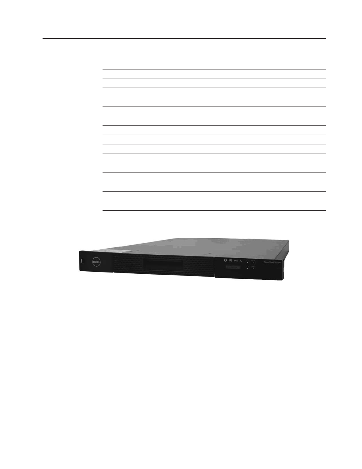
Figure 1-1. TL1000 Tape Autoloader
|
The Dell™PowerVault™TL1000 Tape Autoloader provides compact, high-capacity,
low-cost solutions for simple, unattended data backup. The library has a compact
1U form factor with easy access to tape cartridges with a removable magazine. The
|
TL1000 Tape Autoloader is an external stand-alone or rack-mountable unit that
incorporates an Ultrium 6 Half-High Tape Drive (Model S6H), Ultrium 5 Half-High
|
Tape Drive (Model S5H), or Ultrium 4 Half-High Tape Drive (Model S4H). It is
equipped with a SAS (Serial Attached SCSI) host adapter attachment that has a
data transfer rate of up to 6.0 Gbps.
|
The TL1000 Tape Autoloader has a 10-position removable cartridge magazine,
providing a maximum of 9 data cartridge positions, or a maximum of 8 data
cartridge positions with a configurable 1-slot I/O station. One position is reserved
as the tape drive exchange position and can be accessed by the library only. Tape
|
cartridges that are supported in the TL1000 Tape Autoloader include the 2500 GB
native physical capacity LTO Ultrium Tape Cartridge (Ultrium 6), 1500 GB native
physical capacity LTO Ultrium Tape Cartridge (Ultrium 5), 800 GB native physical
capacity LTO Ultrium Tape Cartridge (Ultrium 4), 400 GB Tape Cartridge (Ultrium
a29z0176
1-1
Page 20
Front panel
3), 200 GB Tape Cartridge (Ultrium 2), and WORM (Ultrium 6, Ultrium 5, Ultrium
4). The library data storage capacity can be further increased by using hardware
compression.
Table 1-1. Data capacity and recording format
Type Native Data Capacity Recording Format
Ultrium 6 2500 GB (6250 GB at 2.5:1
compression)
Ultrium 5 1500 GB (3000 GB at 2:1
compression)
Ultrium 4 800 GB (1600 GB at 2:1
compression)
Ultrium 3 400 GB (800 GB at 2:1
compression)
Ultrium 2 200 GB (400 GB at 2:1
compression)
Ultrium 1 100 GB (200 GB at 2:1
compression)
Reads and writes data on
2176 tracks, 16 tracks at a
time.
Reads and writes data on
1280 tracks, 16 tracks at a
time.
Reads and writes data on 896
tracks, 16 tracks at a time.
Reads and writes data on 704
tracks, 16 tracks at a time.
Reads and writes data on 512
tracks, 8 tracks at a time.
Reads and writes data on 384
tracks, 8 tracks at a time.
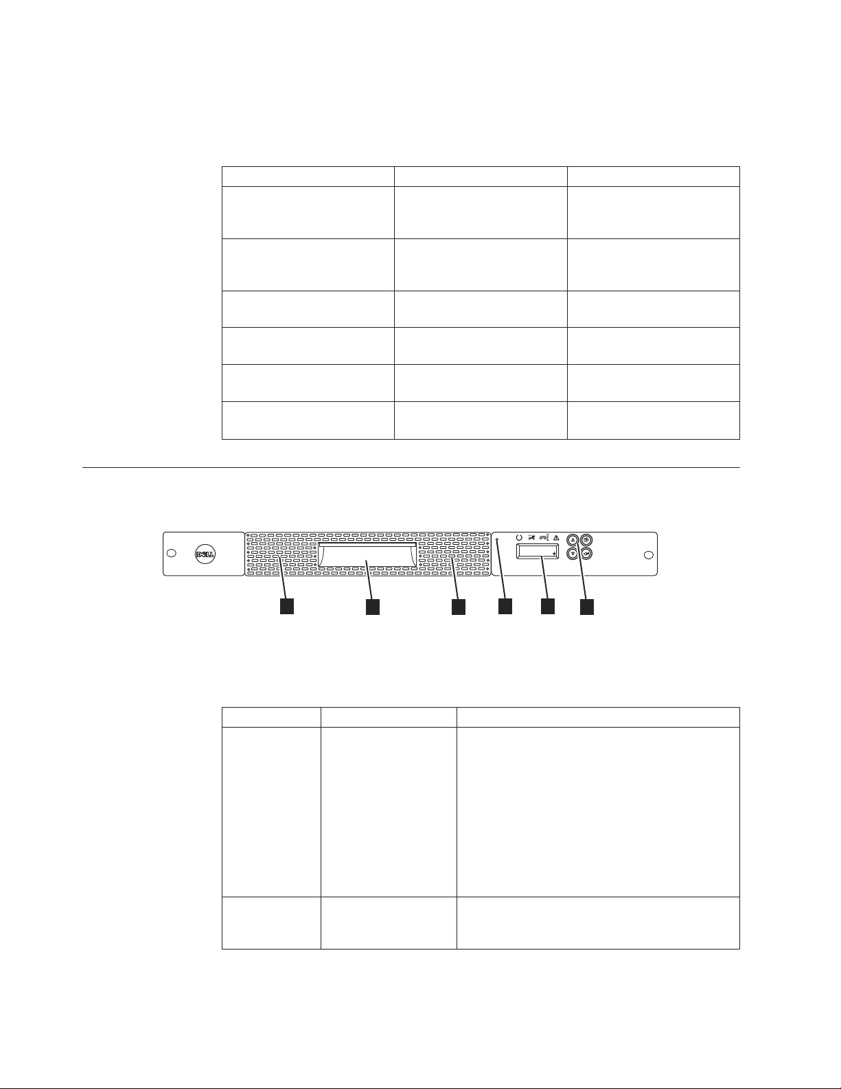
Figure 1-2. Front panel components
2
Table 1-2. Front panel component descriptions
Number Component Description
1 Operator Panel The Operator Panel features a monochrome
2 Control keys The control keys are located to the right of the
2
PowerVault TL1000
a29z0175
UNLOCK
I/O STATION
5
3
5
4
1
16-character LCD graphic display that is on the
front of the library. Library operations and
service functions are completed from this screen.
The Web User Interface offers some of the same
functionality as the Operator Panel with a web
browser for remote access to the library. For
information about the Operator Panel and the
Web User Interface, see Chapter 2, “User
interfaces,” on page 2-1.
Operator Panel LCD display on the front of the
library.
1-2 Dell PowerVault TL1000 Tape Autoloader User's Guide
Page 21

Table 1-2. Front panel component descriptions (continued)
Number Component Description
3 Cartridge magazine The tape library has a single cartridge magazine
that can hold up to 9 data cartridges, or 8 data
cartridges with a 1-slot I/O station. See
Figure 1-3 on page 1-4.
Column 5/Tier 1 in the cartridge magazine can
be configured as a 1-slot I/O station. Column
5/Tier 2 in the cartridge magazine is reserved
for the exchange position and can be accessed by
the library only. The I/O station is used to
import and export cartridges without
interrupting normal library operation. Beginning
with Column 4, a minimum of one column can
be reserved for cleaning cartridges. Cleaning
cartridges are used to clean the tape drive heads.
For configuration details, see Chapter 3,
“Installation and configuration,” on page 3-1.
4 Cartridge magazine
release
|
5 Air vents These vents draw cooler air into the library
Emergency cartridge magazine lock release.
When the I/O station is locked, insert a large,
straightened paper clip twice or hold the paper
clip in place while the cartridge magazine slides
past the I/O station lock.
enclosure and allow warm air to escape which
helps keep the library at a normal operating
temperature.
Chapter 1. Product description 1-3
Page 22
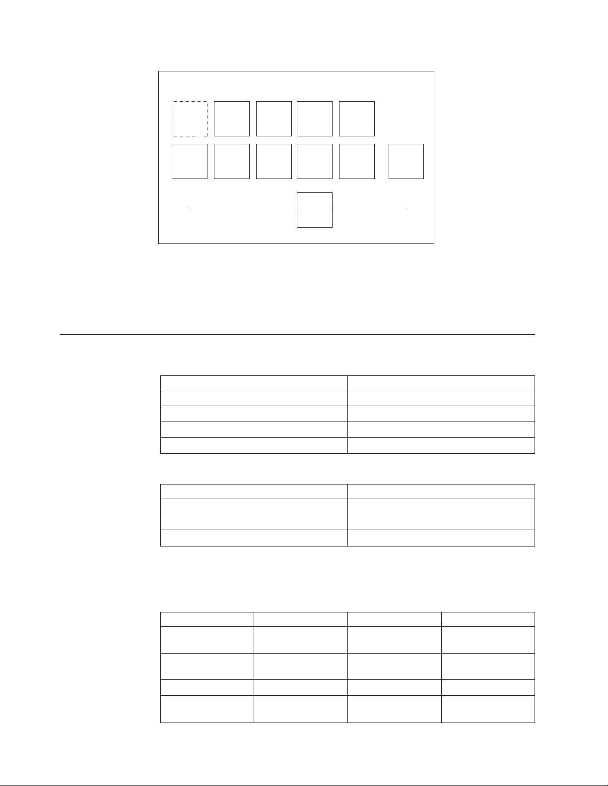
Cartridge magazine
Column 5
Tier 2
Column 4
Tier 2
Column 3
Tier 2
Column 4
Tier 1
Column 2
Tier 2
Column 3
Tier 1
Column 1
Tier 2
Column 2
Tier 1
Column 1
Tier 1
1
3
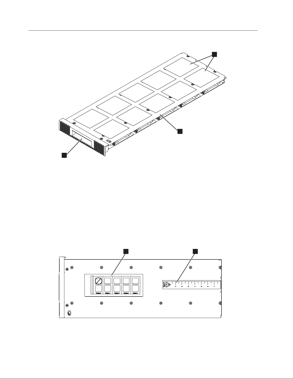
Figure 1-3. Cartridge Magazine
1 Cartridge locations as they appear
Figure 1-4 shows the cartridge location label 1 and ruler 2 that appears on the
cartridge magazine. The ruler provides an indication of the distance, when the
magazine is opened or withdrawn, to the end of the magazine before it clears the
front edge of the library. To prevent dropping the magazine, support both ends of
the magazine before it clears the front edge of the library.
Column 5
Tier 1
in the Library Map.
Note: These labels are for reference
only and do not display on the
magazine.
2
a29z0025
2 Cartridge magazine
3 Magazine handle
21
Figure 1-4. Cartridge magazine (top view)
1-4 Dell PowerVault TL1000 Tape Autoloader User's Guide
a29z0057
Page 23
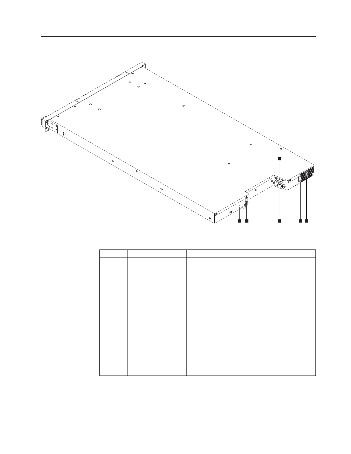
Rear panel
3
Figure 1-5. Rear panel components
Table 1-3. Rear panel component descriptions
Number Component Description
1 Power connector The library connects to a 110/220 volt ac power
2 Power switch The library is powered ON when the power supply
3 SAS host interface
4 Ethernet port This port is used to connect the library to a network.
5 Accessor locking screw The accessor locking screw is used to lock the
6 Air vent These vents allow air to escape from the power
connector
45 1 2 6
supply.
switch on the rear panel is ON (|). The library has no
independent power switch on the front panel.
Serial-attached SCSI host interface cable connection.
The Ultrium 4, 5, and 6 SAS drives use the SFF-8088
connection at the drive end and SFF-8088 or SFF-8470
at the host adapter end.
accessor in place during transportation.
Important: Remove the accessor locking screw before
the library is powered ON.
supply and tape drive sled.
a29z0003
Chapter 1. Product description 1-5
Page 24

Bar code reader
SAS host interface
|
|
|
Encryption
The bar code reader is a part of the library accessor. The bar code reader reads
each cartridge bar code label that identifies the types of cartridge magazines and
tape drive that is installed in the library. It also provides inventory feedback to the
host application, Operator Panel, and Web User Interface. The library stores the
customized inventory data in memory. Library firmware supportsa6or
8-character volume serial number (VOLSER) on the bar code label on the tape
cartridge.
The Ultrium 4, Ultrium 5, and Ultrium 6 Half-High Tape Drives support the Serial
Attached SCSI (SAS) interface. The SFF-8088 SAS connector on the Ultrium 4,
Ultrium 5, and Ultrium 6 is compatible with SAS-1 or SAS-2 cables.
A drive with a SAS (Serial Attached SCSI) interface is linked directly to controllers.
SAS is a performance improvement over traditional SCSI. SAS enables multiple
devices (up to 128) of different sizes and types to connect simultaneously with
thinner and longer cables. Its full-duplex signal transmission supports 6.0 Gb/s
(S4H, S5H, and S6H). In addition, the TL1000 Tape Autoloader is hot-plugged, if
necessary. SAS drives can auto-negotiate speed.
The LTO Ultrium 6, Ultrium 5, and Ultrium 4 Tape Drives support host
Application Managed Encryption (AME) with T10 encryption methods, for SAS
drives. Data encryption is supported by LTO Ultrium 6, Ultrium 5, and Ultrium 4
Data Cartridges only.
Note: Application Managed Encryption (AME) does not require a key.
The encryption enabled drive contains the necessary hardware and firmware to
encrypt and decrypt host tape application data. Encryption policy and encryption
keys are provided by the host application or host server. A drive digital certificate
is installed at manufacturing time. Each drive receives a unique serial number and
certificate. The T10 application validates each drive instance by checking the
drive’s digital certificate.
The LTO Ultrium encryption environment is complex and requires knowledge
beyond that of product trained Service Support Representatives (SSRs). The
Encryption function on tape drives (desktop, stand-alone, and within libraries) is
configured and managed by the customer. In some instances, SSRs are required to
enable encryption at a hardware level when service access or service password
controlled access is required. Customer setup support is by Field Technical Sales
Support (FTSS), customer documentation, and software support for encryption
software problems. Customer 'how to' support is also provided by way of support
line contract.
The encryption-capable library firmware allows the user to select None or
Application Managed encryption from the Web User Interface. The factory default
is None.
1-6 Dell PowerVault TL1000 Tape Autoloader User's Guide
Page 25

Supported Internet Protocols
|
The TL1000 Tape Autoloader supports the Internet protocols:
v IPv4
v IPv6
To learn more about IPv4, visit http://www.iana.org/. To learn more about IPv6,
visit http://www.ipv6.org/..
Simple Network Management Protocol (SNMP) messaging
Occasionally, the library might encounter a situation that you want to know about,
such as an open magazine or a fault that causes the library to stop. The library
provides a standard TCP/IP protocol called Simple Network Management Protocol
(SNMP) to send alerts about conditions (such as need for operator intervention)
over a TCP/IP LAN network to an SNMP monitoring station. These alerts are
called SNMP traps. With the information supplied in each SNMP trap, the
monitoring station (together with customer-supplied software) can alert operations
personnel of possible problems or operator interventions that occur.
SNMP traps
SNMP Traps are alerts or status messages that can be collected, monitored, and
used to proactively manage attached libraries with SNMP protocol with the SNMP
monitoring stations. In summary, each trap provides the following information:
v Product Identification such as product name, description, manufacturer, model
number, firmware level, and the URL that the trap is designated for.
v Product Status such as the severity of the trap, status (current and previous) and
the time the trap occurred.
v Library State (physical device status) such as identification and status of devices
that is monitored. It would include enclosure, power supply, controller,
magazine status, drive count, cartridge slot count, and I/O station count. Also
included would be certain library statistics, and where appropriate, the fault FSC
(fault symptom code) including the severity and description of that fault.
v Drive Status such as the identification of each drive in the library, firmware
level, serial number, and other address and status information.
v Trap Definitions such as library status change, open magazine, I/O accessed,
hard fault information, requests to clean the drive, excessive retries, and
returning to normal operations.
v SNMP MIBs: The library's Management Information Base (MIB) contains units
of information that specifically describe an aspect of the system, such as the
system name, hardware number, or communications configuration. When with
|
SNMP to monitor your TL1000 Tape Autoloader, make sure that the TL1000 MIB
file is loaded on your SNMP monitoring station. SNMP traps are sent to the
SNMP monitoring stations that are defined for your library (see “Configuring
SNMP trap notifications” on page 4-31).
Network Time Protocol
NTP is an Internet standard protocol that assures accurate synchronization of
computer clock times in a network of computers. Running as a continuous
background client program on a computer, NTP sends periodic time requests to a
server, obtaining server time stamps, and with them to adjust the client’s clock.
Chapter 1. Product description 1-7
Page 26
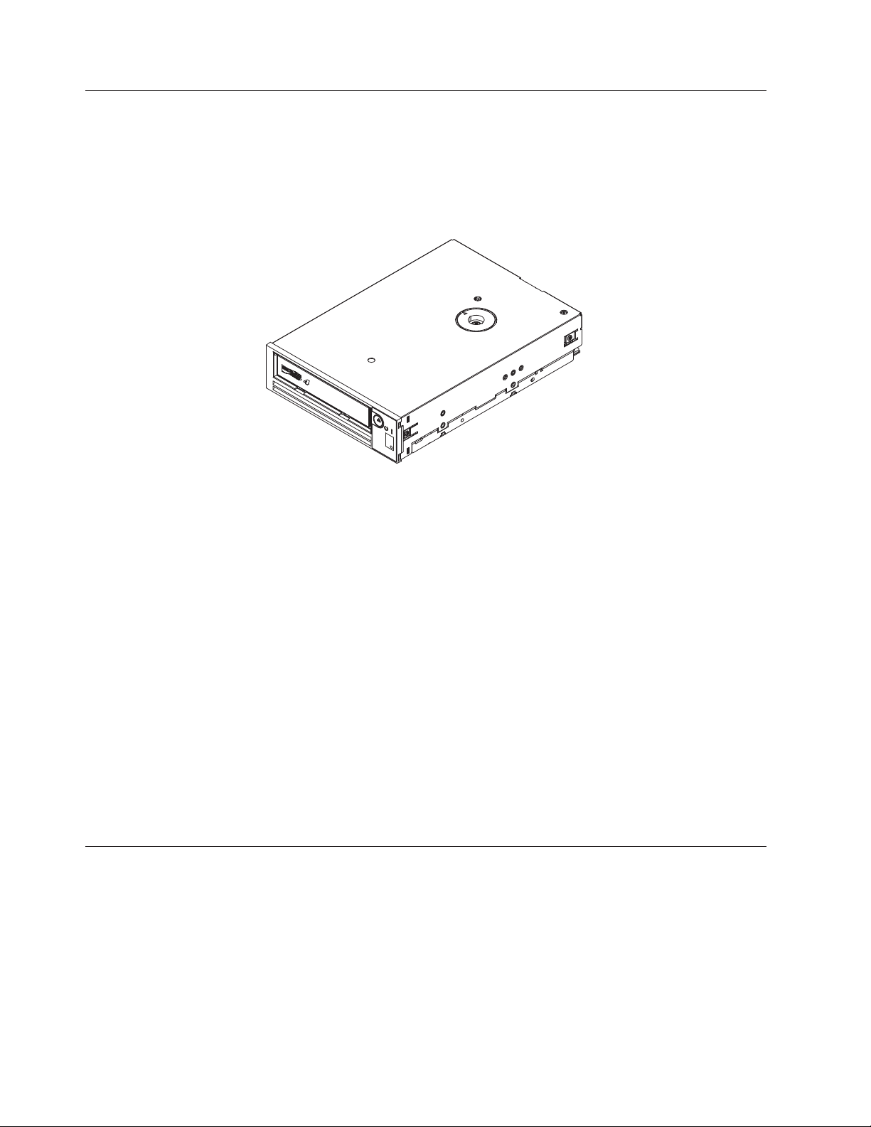
Ultrium tape drives
|
Figure 1-6. Ultrium half-high tape drive
The TL1000 Tape Autoloader supports the Ultrium 4 (S4H), Ultrium 5 (S5H), and
Ultrium 6 (S6H) half-high tape drives.
The Ultrium 4, Ultrium 5, and Ultrium 6 half-high tape drives support the Serial
Attached SCSI (SAS) interface. They have one Mini-SAS (SFF-8088) connector.
Speed matching
a80hh015
Media
|
|
To improve system performance, the Ultrium 4, Ultrium 5, and Ultrium 6 Tape
Drives use a technique that is called speed matching to dynamically adjust its
native (uncompressed) data rate to the slower data rate of the attached server.
Channel calibration
The channel calibration feature of the Ultrium 4, Ultrium 5, and Ultrium 6 Tape
Drives customizes each read/write data channel for optimum performance. The
customization enables compensation for variations in the recording channel
transfer function, media characteristics, and read/write head characteristics.
Power management
The Ultrium 4, Ultrium 5, and Ultrium 6 Tape Drives feature a power management
function. This function controls the drive’s electronics so that part of the electronics
completely turns OFF when circuit functions are not needed for the drive’s
operation.
The TL1000 Tape Autoloader uses Ultrium tape cartridges that provide up to
2500-GB native capacity (up to 6250 GB with 2.5:1 hardware data compression) for
Ultrium 6 tape drives, 1500-GB native capacity (up to 3000 GB with 2:1 hardware
data compression) for Ultrium 5 tape drives, and 800-GB native capacity (up to
1600 GB with 2:1 hardware data compression) for Ultrium 4 tape drives.
1-8 Dell PowerVault TL1000 Tape Autoloader User's Guide
Page 27

Table 1-4. Ultrium data and cleaning cartridge compatibility with Ultrium tape drive
Ultrium
Tape Drive
Ultrium 6 Read/Write Read/Write Read only
Ultrium 5 Read/Write Read/Write Read only
Ultrium 4 Read/Write Read/Write Read only
Ultrium 3 Read/Write Read/Write Read only
Ultrium 2 Read/Write Read/Write
Ultrium 1 Read/Write
2500 GB
(Ultrium 6)
1500 GB
(Ultrium 5)
LTO Ultrium Data Cartridges
800 GB
(Ultrium 4)
400 GB
(Ultrium 3)
200 GB
(Ultrium 2)
100 GB
(Ultrium 1)
|
Note: The TL1000 Tape Autoloader supports the Ultrium 4 (S4H), Ultrium 5 (S5H),
and Ultrium 6 (S6H) Tape Drives only.
For more information about media compatibility, see Chapter 5, “Media,” on page
5-1.
Logical Unit Number (LUN) scanning
|
The TL1000 Tape Autoloader uses a single SCSI ID and dual LUNs to control the
tape drive (LUN 0) and library accessor (LUN 1). The library requires a Host Bus
adapter (HBA) that supports LUN scanning. If it is not enabled, your host system
cannot scan beyond LUN 0 and fails to detect the library. It sees only the tape
drive.
Important: Some HBAs, such as RAID controllers, do not support LUN scanning.
Location coordinates and element addresses
|
The TL1000 Tape Autoloader incorporates patented high-density (HD) slot
technology, which allows multiple cartridges to be stored in a tiered architecture.
The depth of a cartridge location in a high-density slot is known as a tier.
High-density slots are designed to contain multiple cartridges in Tiers 1 and 2.
Note: Each column has a spring-loaded mechanism that pushes a tape cartridge
into Tier 1 when it is the only cartridge in that column. A single cartridge in
a column takes on the Tier 2 element address even though it is physically in
Tier 1.
Chapter 1. Product description 1-9
Page 28
Front Rear
Reserved slot
Column 5
Tier 2
Column 5
Tier 1
Figure 1-7. Location coordinates
A storage element address is assigned to each cartridge at the time the cartridge is
inserted. Storage element addresses range from 4097 to 4105 (0x1001 to 0x1009)
when the I/O station is not enabled, and from 4097 to 4104 (0x1001 to 0x1008)
when the I/O station is enabled.
Library specifications
Table 1-5. Physical specifications
Front panel width (chassis/bezel) 445 mm (17.52 in.)/483 mm (19.02 in.)
Depth 850 mm (33.46 in.)
Height 44 mm (1.73 in.)
Weight (library only) 13 kg (28.66 lbs)
Column 4
Tier 2
Column 4
Tier 1
Column 3
Tier 2
Column 3
Tier 1
Column 2
Tier 2
Column 2
Tier 1
Accessor
Column 1
Tier 2
Column 1
Tier 1
Drive
Parameter Measurement
Table 1-6. Electrical specifications
Parameter Measurement
Voltage 100 - 240 Vac. (4.0 to 1.5 A)
Frequency 50 - 60 Hz
Power consumption 110 W
For more information about installation specifications, see Chapter 3, “Installation
and configuration,” on page 3-1.
Table 1-7. Environmental specifications
Parameter Operating (see Note) Storage Shipping
Temperature
Temperature
variation
10-38°C(50-100
10 °C/hour
(maximum)
Relative humidity 20 - 80% 10 - 90% 10 - 90%
Wet bulb temperature
26 °C (78.8 °F)
1-10 Dell PowerVault TL1000 Tape Autoloader User's Guide
°F)
maximum
1 - 60 °C (34 - 140 °F)
10 °C/hour
(maximum)
29 °C (84 °F)
maximum
-40 to 60 °C (-40 to
140 °F)
10 °C/hour
(maximum)
29 °C (84 °F)
maximum
Page 29

Table 1-7. Environmental specifications (continued)
Parameter Operating (see Note) Storage Shipping
Altitude (meters) 0 - 2,500 0 - 2,500 0 - 2,500
Note: The operating environment of the library must not conflict with the media storage
requirements. The library can operate at elevated temperatures for an extended period.
However, the temperature might shorten the useful life of media that is stored in the
library. If media is stored in the library for more than 10 hours, the storage temperature
requirements for media are met. It is assumed that media stored in the library is
approximately 2 degrees above ambient temperature when the library is powered ON.
Table 1-8. Operational specifications
Parameter Model S6H Model S5H Model S4H
Maximum storage
capacity
Maximum number of
data cartridges
Drive types Ultrium 6 Half High Ultrium 5 Half High Ultrium 4 Half High
Sustained native data
transfer rate
Interface 6 Gb/s SAS 3 Gb/s SAS
Note: The Ultrium 4 Half-High tape drive in S4H libraries that are manufactured after
March 2011 support 6.0 Gb/s and a sustained native data rate of 120 Gb/s.
22.5 TB (56.2 TB with
2.5:1 compression)
9 (including an optional I/O Station)
160 MB/s (320 MB/s
with 2:1
compression)
13.5 TB (27 TB with
2:1 compression)
140 MB/s (280 MB/s
with 2:1
compression)
7.2 TB (14.4 TB with
2:1 compression)
120 MB/s (240 MB/s
with 2:1
compression)
Table 1-9. Acoustical specifications
Idling acoustical noise sound power level
LwAD in Bels (1 Bel = 10 dB)
Maximum acoustical noise sound power
level LwAD in Bels (1 Bel = 10 dB)
Product environment
|
The TL1000 Tape Autoloader is designed to operate in a general business
environment.
The library meets the acoustical requirements for general business area category
2D. Category 2D states that the library can be installed a minimum of 4 m (13 ft.)
from a permanent work station.
To allow for service access, install the library a minimum of 0.9 m (3 ft.) from all
obstacles.
The library is a precision computer peripheral device. To ensure maximum
longevity of your library, locate the library away from dust, dirt, and airborne
particulates, as follows:
v Keep the library away from high-traffic areas, especially if the floor is carpeted.
Parameter Measurement
6.6
6.8
Carpeting harbors dust and walking on the carpet can cause the carpet fibers
and the dust to become airborne.
Chapter 1. Product description 1-11
Page 30

v Keep the library out of printer and copier rooms because of toner and paper
dust. Additionally, do not store paper supplies next to the library.
v Keep the library away from moving air caused by doorways, open windows,
fans, and air conditioners.
Ensure that the machine covers are always kept closed to minimize any
contamination from airborne particles.
Supported device drivers
Device drivers enable the drive to interact with various servers. For applications
that use device drivers, see the application’s documentation to determine which
drivers to use.
Note: If you do not have Internet access and you need information about device
drivers, contact your sales representative.
1-12 Dell PowerVault TL1000 Tape Autoloader User's Guide
Page 31

Chapter 2. User interfaces
“Operator Panel”
“Web User Interface” on page 2-5
The library has a local interface, the Operator Panel, and a remote Web User
Interface (UI).
The Operator Panel is on the front of the library and allows users to work locally
on the library. The Web User Interface allows users and administrators to view and
perform some library functions from remote sites.
The Web User Interface is implemented as a Java
browser from any PC on the network. The Java Applet requires that Java 1.5.0 or
higher is installed on your host computer for full functionality, and is best viewed
with Internet Explorer 6.0 or higher. Internet Explorer 7.0 or higher is required for
IPv6.
Operator Panel
The Operator Panel is on the front bezel of the library. The Operator Panel displays
library information and menu commands that are used to run library management
functions in response to the control keys on the right of the LCD display.
™
Applet that runs in a web
6
Figure 2-1. Operator Panel components
Table 2-1. Operator Panel component descriptions
Number Component Description
1 LCD display 16-character LCD graphic display
|
|
2 Up key (Δ) Button that is used to navigate upward (↑) through the menu
3 Down key (∇) Button that is used to navigate downward (↓) through the
7
8
1
9
items
menu items
2
3
4
5
a29z0177
2-1
Page 32

Table 2-1. Operator Panel component descriptions (continued)
Number Component Description
4 Cancel key Button that is used to cancel a user action and return to the
last menu item
5 Enter key Button that is used to display a submenu or to select a user
action
6 Ready/Activity
LED
7 Clean Drive
LED
8 Attention LED Amber LED lit when a cartridge is incompatible with the
9 Error LED Amber LED lit when there is an unrecoverable library or
Green LED lit when the unit is powered ON. The LED
flashes when there is any library activity or the library is
offline.
Amber LED lit when the drive needs cleaning. The LED
turns OFF after the drive is cleaned successfully.
drive, marginal, or invalid. The LED turns OFF when the
media is removed from the drive. The LED might also be lit
when there is a power supply problem.
drive failure. The corresponding error message displays on
the LCD display.
The Operator Panel operates in two basic modes:
v User Interaction mode - Mode that is employed when a user is pushing keys on
the Operator Panel.
v System Driven mode - Normal mode of operation where the Operator Panel
displays status in response to commands issued from the drive's internal
interface.
When an Operator Panel key is pressed and released, the Operator Panel
automatically changes to User Interaction mode. User Interaction mode continues
until 3 minutes after a user stops pushing keys, or the requested accessor action
stops, whichever is longer. Then, the Operator Panel returns to System Driven
mode.
If necessary, the Operator Panel automatically changes to System Driven mode.
When this change occurs, the library remembers what the user was doing before
the display mode changed.
Any operational conflict between commands that are received over the host
interface or the Web User Interface and those commands that are entered by way
of the Operator Panel are avoided with a reservation mechanism on a first-come,
first-served basis. Operator Panel commands are canceled by an Operator Panel
logout or timeout.
Library firmware does not allow a user to select an impossible request. Those
situations include, but are not limited to -
v Moving a cartridge from any source to a position occupied by another cartridge
v Moving a cartridge from an empty cartridge position
v Loading a cartridge from any source to a full drive
v Unloading a cartridge from an empty drive
Any error that is detected by the library or drive controller and not recoverable
through predetermined firmware algorithms is considered unrecoverable. When an
error occurs, an error code is displayed on the Operator Panel display and the
2-2 Dell PowerVault TL1000 Tape Autoloader User's Guide
Page 33

error LED is ON. The error code remains on the Operator Panel until a key is
pressed, which causes the Operator Panel to return to the Home Screen. Numeric
error codes are used for unrecoverable errors. Otherwise, text status messages are
displayed.
When the library powers ON or resets, it goes through several internally controlled
initialization processes, called the Power-On-Self-Test (POST).
Front panel LEDs
All LEDs are updated during power ON and reset sequences. At power ON or
software reset, all LEDs turn ON as soon as POST allows. When initialization
starts, all LEDs turn OFF and the Ready/Activity LED flashes at a rate of
approximately 2 seconds per cycle. When the mechanical initialization is complete,
the Ready/Activity LED stops flashing and turns ON.
If a library failure occurs, the Ready/Activity LED turns OFF and the Error LED
turns ON. The Operator Panel also displays an appropriate error code to help
identify the failure.
The following are more operational details of LEDs:
v The Ready/Activity LED (6 in Figure 2-1 on page 2-1) turns ON any time the
unit is powered ON and functional. The Ready/Activity LED flashes whenever
there is library. This LED also flashes when the library is offline.
v The Clean Drive LED (7 in Figure 2-1 on page 2-1) turns ON when a
“cleaning required” command is issued by the drive. The LED turns OFF after a
successful drive cleaning operation.
v The Attention LED (8 in Figure 2-1 on page 2-1) turns ON to indicate that a
piece of media is bad/marginal, or invalid. The LED turns OFF when all
marginal and invalid cartridges are exported from the library. The Attention LED
also turns ON if Autoclean is enabled and no cleaning cartridge is in a cleaning
position.
v The Error LED (9 in Figure 2-1 on page 2-1) turns ON when there is an
unrecoverable drive or library failure. An error message is displayed on the
screen and the LED remains ON until the error state is resolved.
For information, see “Interpreting front panel LEDs” on page 6-8.
Input modes
There are several ways to enter values in the different menu items. These values
are selectable predefined values, toggle values (for example, ON/OFF) and
numerical values like network addresses.
Selecting predefined values
1. To set the predefined values, press the Enter key to select the menu item.
2. With the Plus and Minus keys, select one of the various predefined values for
that item.
3. As soon as the Operator Panel display shows the correct value, press the Enter
key to apply the value.
Toggling values
Toggle values are used to switch between two different states like ON and OFF.
Chapter 2. User interfaces 2-3
Page 34

1. After you navigate to the menu item, press the Enter key to select the menu
item.
2. With the Plus and Minus keys, select one of the various predefined states for
that item.
3. Press the Enter key to apply the new state.
Entering numerical values
Numerical values are needed for network addresses, password entries, and other
configuration entries.
1. After you navigate to the menu item, the current value is displayed and the
cursor highlights the first digit of the value that can be changed.
2. For each digit to be changed in the value:
a. Use the Plus and Minus keys to increment or decrement the digit.
b. Press the Enter key to highlight the next editable digit.
3. Press the Enter key at the last digit to apply the complete entry. Press the
Cancel key to cancel the whole edit process and maintain the original value.
Logging in
At power ON or software reset, the library ready screen displays when POST
initialization completes successfully.
Figure 2-2. Library ready screen
To log in to the Operator Panel, press the Enter key. The password entry screen
displays.
Figure 2-3. Password entry screen
Press the UP and DOWN arrow keys to change the current digit. Press the Enter
key to advance to the next digit. The default password is 0000. When you are
logged in, you can change the password with the Change Login Password
command. See “Configuring Operator Panel settings” on page 4-13.
a29z0028
a29z0029
2-4 Dell PowerVault TL1000 Tape Autoloader User's Guide
Page 35

Screen elements
Figure 2-4. Screen elements
The Operator Panel displays a single menu item (1 in Figure 2-4) on each screen.
The existence of other menu items above and below the currently displayed item is
indicated by the arrows (2 in Figure 2-4) on the right side of the screen.
In the Configuration menu, the current configuration setting is indicated by an
asterisk (3 in Figure 2-4) on the right side of the screen. For example, in
Figure 2-4, the I/O station is enabled. When a configuration setting is changed, the
confirmation screen in Figure 2-5 displays. Press the Enter key to confirm, or
Cancel to return to the previous screen.
Figure 2-5. Confirmation screen
1
2
3
a29z0030
a29z0032
Web User Interface
|
The Web User Interface Java Applet requires Java 1.5.0 or higher be installed on
your host computer for full function, and is best viewed with Internet Explorer 6.0
or higher. Internet Explorer 7.0 or higher is required for IPv6. If your computer
does not have Java installed or you must upgrade your installation, download the
latest version of the Java Runtime Environment (JRE) for your platform from
http://www.java.com/. Follow the instructions that are provided to enable and
configure the Java Runtime Environment for your browser.
The Web User Interface can also be used to update the library and drive firmware,
and to download error logs, drive memory dumps, and other library data.
Before the TL1000 Tape Autoloader can be managed over a network with the Web
User Interface, set up the initial network configuration of the library with the
Operator Panel. For information, see “Configuring network settings” on page 3-24.
Logging in
To log in to the Web User Interface from Internet Explorer, you must enter the IP
address of the library. The IP address can be obtained with the View Settings
command from the Operator Panel. For example, http://192.168.1.1.
When the applet starts, the following warning message displays. This message is
normal and does not indicate a problem.
Chapter 2. User interfaces 2-5
Page 36

Figure 2-6. Java security warning message
After the Web User Interface is started, the login window is displayed.
4
a29z019
Figure 2-7. Login page
The factory default account login and password for an Administrator account is
v Account: admin
v Password: secure
The account name and password are case-sensitive. After your account name and
password are entered, use your mouse to click Login or press the Enter key.
For information about account privileges, see “User privileges” on page 2-8.
Common header elements
All Web User Interface windows (except for the Login screen) contain the
following common elements in the header
v Help - Click to read context-sensitive help for the associated page.
2-6 Dell PowerVault TL1000 Tape Autoloader User's Guide
a29z0195
Page 37

v Logoff - Click to log out of the Web User Interface.
Menus available from the Web User Interface
Figure 2-8 shows the Web User Interface window for a User account, Figure 2-9
shows the window for a Superuser account, and Figure 2-10 on page 2-8 shows the
window for an Administrator account.
Figure 2-8. User account window
Figure 2-9. Superuser account window
a29z0196
a29z0197
Chapter 2. User interfaces 2-7
Page 38

Figure 2-10. Administrator account window
For a complete description of all Web User Interface menu options, see Chapter 4,
“Operations,” on page 4-1.
User privileges
User privilege levels are manually assigned to user accounts created within the
library. Controlling access to screens and operations within the library preserves
the integrity of the library and the data that is stored within the library.
There are three types of user privileges in the library.
v Users are allowed to monitor the library, but not complete actions that affect the
physical library.
v Superusers are allowed to operate the physical and logical library, but not
complete actions that affect the library configuration.
v Administrator users are allowed access to the entire physical library and logical
library, including configuration. Only one administrator user must be assigned
the login name admin.
User privileges include
v Multiple users can be logged in at one time on the Web User Interface.
v Any user can be logged in to only one interface at a time.
a29z0198
2-8 Dell PowerVault TL1000 Tape Autoloader User's Guide
Page 39

Chapter 3. Installation and configuration
“Choosing a location”
|
“Installing in a rack” on page 3-2
“Removing the accessor locking screw” on page 3-7
“Attaching the library to a server” on page 3-8
“Configuring your library with the
Web User Interface” on page 3-11
“Configuring your library with the
Operator Panel” on page 3-24
“Populating the library with cartridges” on page 3-27
“Verifying library and drive operation” on page 3-28
“Taking the Library Online” on page 3-29
“Registering for support notification” on page 3-29
“Logging in to the Web User Interface” on page 3-12
“Checking firmware level” on page 3-13
“Configuring library settings” on page 3-14
“Configuring network settings” on page 3-16
“Configuring date and time settings” on page 3-17
“Configuring encryption settings” on page 3-18
“Configuring email notifications” on page 3-20
“Configuring trap notifications” on page 3-21
“Managing user access” on page 3-23
“Saving the library configuration” on page 3-24
“Logging in to the Operator Panel” on page 3-24
“Configuring network settings” on page 3-24
“Configuring library settings” on page 3-26
|
To install and configure a TL1000 Tape Autoloader, complete these procedures in
the order they are presented.
Choosing a location
Table 3-1. Location criteria
Criteria Definition
Room temperature 16 - 32 °C (60 - 90 °F)
Voltage 100 - 240 Vac. (4.0 to 1.5 A)
Note: The power switch is on the rear of the
library and must be easily accessible.
Frequency 50 - 60 Hz
Relative humidity 20 - 80% non-condensing
Air quality The library must be placed in an area with
minimal sources of particulate
contamination. Avoid areas near frequently
used doors and walkways, stacks of supplies
that collect dust, printers, and smoke-filled
rooms. Excessive dust and debris can
damage cartridges and the tape drive.
3-1
Page 40

Table 3-1. Location criteria (continued)
Criteria Definition
Clearance
Rack requirements Standard EIA 19-inch rack: 1U space
Installing in a rack
v Back: Minimum of 15 cm (6 in.)
v Front: Minimum of 30 cm (12 in.)
v Sides: Minimum of 5 cm (2 in.)
|
The TL1000 Tape Autoloader can be easily installed into a standard 19-inch rack
system. A standard 19-inch rack system contains multiple mounting locations that
are called EIA units as defined by the Electronics Industries Association. Each EIA
unit contains three square or round holes that are used to mount rack designed
equipment. The library requires 1 EIA unit (1U) of rack space. Each unit is
separated by a small space.
When you decide on a location in your rack for the library, consider that the
Operator Panel has a small LCD screen. The library must be positioned to allow
for easy viewing. The rear of the library must be free from any obstructions to
allow easy access to the power switch and other rear panel components.
Note: Before you begin the rack installation of the library, read the safety
information in “Rack safety” on page xiii. Also, verify that no desktop feet
are attached to the bottom of the library.
To install the library in a rack:
1. Verify that your rack kit includes all the necessary contents.
2. Determine the location in your rack for your library to be installed. With a
pencil, mark the location on the front vertical rails and rear vertical rails
(Figure 3-1 on page 3-3) in your rack.
3-2 Dell PowerVault TL1000 Tape Autoloader User's Guide
Page 41

Figure 3-1. Rack mount screw locations for front and rear vertical rails
|
a29z0015
|
3. Place the screws 11 into the left and right brackets.
|
|
|
4. Attach the left 3 and right 4 (Figure 3-2 on page 3-4) front brackets to the
front of the library chassis with 2 flat-head screws 8 on each side. Use the
|
|
top two screw holes on each side. The flange of each bracket with the inserted
screws (11) fits into the cutout on each side of the bezel.
Chapter 3. Installation and configuration 3-3
Page 42

|
8
|
Figure 3-2. Attaching the front brackets to the library chassis
|
3
11
|
5. Attach the left 1 and right 2 rear brackets to the left 5 and right 6
front rails with 2 round-head screws 10 on each side (Figure 3-3).
4
8
a29z0185
1
Figure 3-3. Attaching the rear brackets to the rails
Important: Do NOT tighten these screws completely.
6. Slide in the rear rails 7 from back to front, to create the rail assemblies.
Ensure that the screw holes face outwards (Figure 3-4 on page 3-5).
12
2
10
5
6
a29z0019
3-4 Dell PowerVault TL1000 Tape Autoloader User's Guide
Page 43

Figure 3-4. Creating the rail assemblies
7. Install the rail assemblies into the rack (Figure 3-5 on page 3-6). Ensure the 3
holes in the front of the unit align with the 1U space marked on the vertical
rails in Step 2. Secure the rails to the rack with 4 flat-head screws 9 on each
|
|
side of the rack. Use the top and bottom screw locations on the front and rear
of the rack rail (Figure 3-1 on page 3-3)).
7
a29z0018
Chapter 3. Installation and configuration 3-5
Page 44

9
Figure 3-5. Installing the rail assemblies
9
a29z0020
|
|
|
8. Slide the library chassis into the rack. The heads of the large screws 11
appear through the oval openings on each side of the bezel. Use a Phillips
screwdriver to attach these screws to the rack (Figure 3-6).
|
|
Figure 3-6. Securing the front of the library in the rack
|
|
3-6 Dell PowerVault TL1000 Tape Autoloader User's Guide
a29z0186
Page 45

9. Secure the rear of the library to the rack with a round-head screw 10 on
each rear bracket (Figure 3-7). Tighten the other rear bracket screws to secure
the library to the rack.
Figure 3-7. Securing the rear of the library in the rack
10. Run the SAS cable, power cable, and Ethernet cable through the
hook-and-loop fastener strap 12. Leave enough slack to reach the
corresponding connectors, then tighten the strap (Figure 3-8).
1010
a29z0022
12
Figure 3-8. The cables at the rear of the library
Note: For information about converting and relocating the library, see
Chapter 8, “Removal and replacement procedures,” on page 8-1.
Removing the accessor locking screw
Important: The accessor locking screw prevents the library accessor from moving
during shipment and must be removed before the library is powered
ON.
Remove the accessor locking screw, located on the rear panel of the library (1 in
Figure 3-9 on page 3-8).
a29z0023
Chapter 3. Installation and configuration 3-7
Page 46

Figure 3-9. accessor locking screw
Attaching the library to a server
The drive is attached to a server with the Serial Attached SCSI (SAS) interface. The
Web User Interface accesses the library with an ethernet interface.
Connecting the Host Interface cables
To connect the host interface cable to the library:
Note: It is recommended that you shut down and turn OFF the associated server
before you connect the SAS interface cable. Turn ON the associated server
after the SAS interface cable is connected to the library and server, the
library is powered ON, and the library completed the initialization.
1
a29z0102
1 2 3
Figure 3-10. Interface cable connection
1. Attach an ethernet cable to the ethernet port (1 in Figure 3-10)
Note: On rack mount installations, run the cable through the hook-and-loop
fastener strap on the right rear bracket.
3-8 Dell PowerVault TL1000 Tape Autoloader User's Guide
29z0100
Page 47

2. Attach the host end of the SAS cable to the drive’s SAS connector (2 in
Figure 3-10 on page 3-8). See “SAS host interface” on page 1-6 for information
about the type of SAS connector that is required for attachment to the drive.
Note: On rack mount installations, run the cable through the hook-and-loop
fastener strap on the right rear bracket.
3. Attach the other end of the host SAS interface cable to the host or to an
interposer if required.
4.
v Method 1: Plug the ethernet cable into your server or PC to access the Web
User Interface directly. This method modifies your server or PC network
settings to match the library default settings. You can also use the library
Operator Panel to change the library network settings to match the server or
PC network settings before you use the Web User Interface to access the
library. If the ethernet connection is directly attached to a server or a PC, a
crossover ethernet cable might be required.
v Method 2: Plug the ethernet cable into an ethernet switch or router to access
the Web User Interface on a LAN (local area network). The library network
settings must be entered with the Operator Panel before the Web User
Interface is used to access the library.
Connecting the power cord
Important: This product can ONLY be used with an approved power cord for your
specific geographic region. Use of an unapproved power cord might result in
v Not meeting individual country-specific safety requirements
v Overheating with potential personal injury or property damage
v A fracture that results in internal contacts that are exposed, which might subject
the user to a shock hazard
To connect a power cord:
1. Plug one end of the power cord or rack PDU power cord into the power
connector (3 in Figure 3-10 on page 3-8) on the rear panel of the library.
Note: On rack mount installations, run the rack PDU power cord through the
hook-and-loop fastener strap on the right rear bracket, and tighten the
strap. The rack PDU power cord is a special power cord that plugs into a
rack power strip.
2. Plug the other end of the power cord into the nearest properly grounded
power outlet. On rack mount installations, plug the other end of the rack PDU
power cord into the nearest rack PDU.
3. Power ON the library by toggling the power switch on the power supply to the
ON (|) position.
4. Wait for the library to initialize.
During initialization, the library completes a Power ON Self Test (POST) to
ensure that the library hardware is functional. The library also tests
communications with the tape drive over the internal bus.
Note: If the Operator Panel does not initialize, check all cable connections, and
ensure that the cartridge magazine is closed and in the locked position.
Ensure that the power supply switch is in the ON position. If the Operator
Panel still does not initialize, see Chapter 6, “Troubleshooting,” on page 6-1.
Chapter 3. Installation and configuration 3-9
Page 48

Important: To disconnect all power from the library, turn the power switch to the
Note: When the library is power-cycled, wait 10 seconds after the power is OFF
before the library is powered ON again.
Configuring the library
The library can be configured with the Web User Interface or the Operator Panel.
The preferred method for configuring your library is by using the Web User
Interface. See “Configuring your library with the Operator Panel” on page 3-24
and “Configuring your library with the Web User Interface” on page 3-11.
For complete detailed information about all of the functions available on the
library with the Operator Panel and the Web User Interface, see Chapter 4,
“Operations,” on page 4-1.
The default library configuration settings are listed in Table 3-2.
Table 3-2. Default library configuration settings
Ethernet link speed Auto
SSL security Disabled
IPv4 settings Enabled
DHCP (Dynamic Host Configuration
Protocol)
Static IP address Disabled
IPv4 address 0.0.0.0
Subnet mask 255.255.255.0
Gateway 0.0.0.0
IPv6 settings Disabled
DHCP (Dynamic Host Configuration
Protocol)
Stateless auto-configuration Enabled
Static IP address Disabled
IPv6 address 0:0:0:0:0:0:0:0
Prefix length 64
Gateway 0:0:0:0:0:0:0:0
DNS setting Disabled
DNS IP address 0.0.0.0
Library name (Blank)
Auto Cleaning Disabled
Bar code label length 8 characters
OFF position, then remove the power cord from the outlet. The power
switch removes power from portions of the library and the drive, but
the power supply still has ac power at its input.
Configuration Item Default Setting
NETWORK
Enabled
Enabled
PHYSICAL
LOGICAL
3-10 Dell PowerVault TL1000 Tape Autoloader User's Guide
Page 49

Table 3-2. Default library configuration settings (continued)
Configuration Item Default Setting
Library mode Random
Loop Enabled
Auto Load Enabled
Active slots 9 + 0
ENCRYPTION
Encryption method None
DATE and TIME
NTP server Disabled
NTP server address 0.0.0.0
Time zone (GMT) +00:00
Date (MM/DD/YYYY) 01/08/2008
Auto adjustment by PC Every 1 minute
NOTIFICATIONS
SMTP (mail) settings
Mail server address 0.0.0.0
Mail event Error events enabled
SNMP (trap) settings
Community Public
Trap event Error events enabled
SNMPv3 engine ID (Set by library firmware)
Static library network settings must be entered with the Operator Panel before the
library can be accessed remotely with the Web User Interface. If your system is
serviced by a Dynamic Host Configuration Protocol (DHCP) server, the network
parameters are automatically set. Once remote access is established, you can
complete the configuration of your library remotely.
If you choose to use the Operator Panel to configure your library, go to
“Configuring your library with the Operator Panel” on page 3-24.
Configuring your library with the Web User Interface
If you choose to use the Web User Interface to configure your library, first enter
your library network settings with the Operator Panel (see “Configuring network
settings” on page 4-12).
To configure your library with the Web User Interface:
1. Install Java 1.5.0 or higher on your host computer. Download the latest
version of the Java Runtime Environment (JRE) for your platform from
http://www.java.com/.
2. “Logging in to the Web User Interface” on page 3-12
3. “Checking firmware level” on page 3-13
4. “Configuring library settings” on page 3-14
5. “Configuring network settings” on page 3-16
6. “Configuring date and time settings” on page 3-17
Chapter 3. Installation and configuration 3-11
Page 50

7. “Configuring encryption settings” on page 3-18
8. “Configuring email notifications” on page 3-20
9. “Configuring trap notifications” on page 3-21
10. “Managing user access” on page 3-23
11. “Saving the library configuration” on page 3-24
Logging in to the Web User Interface
To log in to the Web User Interface:
1. If necessary, obtain the IP address of the library on the Operator Panel.
a. From the top menu of the Operator Panel, press the Minus key to select
View Current Information, and press Enter.
b. Press the Minus key until the IP Address setting is displayed and make a
note of the IP address.
c. Press the Cancel key repeatedly to log out of the Operator Panel.
2. Open Internet Explorer on your server or PC to access the Web User Interface.
3. In the browser address field, enter your library's IP address URL to start the
Web User Interface applet in the browser window. For example,
http://192.168.1.1
When the applet launches, the warning message in Figure 3-11 displays. This
message is normal and does not indicate a problem.
4. Click Run.
Figure 3-11. Java security warning message
5. On the Web User Interface login screen, enter the administrator login account
name and default password.
v Account: admin
v Password: secure
3-12 Dell PowerVault TL1000 Tape Autoloader User's Guide
4
a29z019
Page 51

Figure 3-12. Web User Interface login screen
6. Click Login.
Checking firmware level
a29z0099
Figure 3-13. System summary
Check the current level of library firmware that is displayed in the System
Summary. If an updated level of firmware is available, download and update the
library firmware before normal operation starts. See “Updating library and drive
firmware” on page 4-38.
3
a29z019
Chapter 3. Installation and configuration 3-13
Page 52

Configuring library settings
Logical library settings
Figure 3-14. Logical library mode settings
To configure the library access mode settings for the logical library:
1. Expand Configure Library, if necessary, and click Logical in the left navigation
pane of the Web User Interface.
2. Select the Library Mode.
v Random - In random mode, the library allows the server's (host's)
application software to select any data cartridge in any order.
v Sequential - In sequential mode, the library's firmware predefines the
selection of the cartridges. After initialization, the firmware causes the library
to select the first available cartridge found (counting from the lowest
Column/Tier position through the highest cartridge position in your library)
for loading into the drive. See “Location coordinates and element addresses”
on page 1-9.
– Loop - Sequential mode with loop mode ON loads the cartridge in the
lowest Column/Tier cartridge position after the cartridge in the highest
Column/Tier cartridge position is filled with data and sent back to its
home position. This mode allows endless backup operations without user
interaction.
– Autoload - Sequential mode with autoload mode ON loads the first
available cartridge (the lowest Column/Tier cartridge position that
contains a cartridge) automatically if the library powers ON, or resets,
with an empty drive. If the library powers ON with a cartridge already in
the drive, sequential mode starts from the home position of that cartridge,
unless the host issues a rewind and unload command to the drive. In
which case the next cartridge in sequence will be loaded into the drive.
To start sequential mode if autoload is OFF, use the Move Cartridge
command to load the first cartridge into the drive. The sequence starts from
the home position of that cartridge. Cartridges need not to be in contiguous
slots.
To stop sequential mode, use the Move Cartridge command to unload the
drive. This command cancels sequential mode; the next sequential cartridge
is NOT loaded.
To restart sequential mode, use the Move Cartridge command again to load a
cartridge; the loading sequence resumes from the home position of that
cartridge.
v Number of active slots - Select the number of active slots you would like to
assign in your library. Selecting the number of active slots defines the
number of storage slots, number of cleaning/inactive slots, whether the I/O
Station is enabled/disabled, and whether auto cleaning is allowed. The first
digit configures the number of active storage positions (4, 6, 8, or 9). The
a29z0124
3-14 Dell PowerVault TL1000 Tape Autoloader User's Guide
Page 53

second digit configures Column 5, Tier 1 of the magazine as an I/O Station
(0 when disabled, and 1 when enabled). The Auto Cleaning function can be
enabled only if there is at least one inactive position in the magazine. If Auto
Cleaning is enabled, the inactive positions become cleaning cartridge
positions.
3. Click Submit to enable the settings.
Physical library settings
Figure 3-15. Cartridge assignment settings
To configure the library cartridge assignment settings, complete the following
procedure:
1. Expand Configure Library, if necessary, and click Physical in the left
navigation pane of the Web User Interface.
2. Select the Library settings.
v Library name - Enter a name for your library.
v Auto Cleaning - Automatically cleans the drive when the drive requests that
cleaning and a cleaning cartridge is present in the library. Auto cleaning can
be enabled only when there is at least one inactive position in the magazine
in the library.
v Bar code label length - Use to choose the number of characters in the
cartridge bar code that is reported to the host computer.
3. Click Submit to enable the settings.
a29z0123
Chapter 3. Installation and configuration 3-15
Page 54

Configuring network settings
Figure 3-16. Network settings
Once the network settings are entered on the Operator Panel, the current network
configuration of the library can be modified with the Web User Interface. The
changes that are made to the network settings do not take effect until after the
library is rebooted.
a29z0125
To modify the network settings:
1. Expand Configure Library, if necessary, and click Network in the left
navigation pane of the Web User Interface.
2. Select the Ethernet Link speed (duplex mode).
3. Select the TCP/IP settings. To enable dual IPv4/IPv6 protocol, select both Use
IPv4 and Use IPv6 and enter parameters for both.
v Security - Select Enable SSL for Web to provide secure communications
between the web browser and the tape library.
v IPv4 setting - Select Use IPv4 to enable the IPv4 Internet Protocol. Select the
corresponding button to obtain an IP address automatically (DHCP) or use
static IP address settings. When with DHCP, use the Operator Panel to
determine the library's assigned IP address. See “Configuring network
settings” on page 4-12. Enter the following parameters if with static IP
address settings.
– IPv4 address - Sets the TCP/IPv4 address of the library on the network.
– Subnet mask - Defines and limits users within a local network.
– Gateway - Allows access outside the local network.
v IPv6 setting - Select Use IPv6 to enable the IPv6 Internet Protocol. Select the
corresponding button to obtain an IP address automatically (DHCP), to
obtain an IP address with stateless auto configuration, or use static IP
address settings. Enter the following parameter if with static IP address
settings.
– IPv6 address - Sets the TCP/IPv6 address of the library on the network.
3-16 Dell PowerVault TL1000 Tape Autoloader User's Guide
Page 55

– Prefix length - Decimal value that indicates the number of contiguous,
– Gateway - Allows access outside the local network.
v DNS setting - Select Use DNS to use a domain name server. The DNS
server, if entered, allows the encryption, date and time, and notifications IP
addresses to be specified with host names instead of numerical IP addresses.
– DNS IP address - Sets the IP address of the DNS server.
4. Click Submit to enable the settings.
Configuring date and time settings
Figure 3-17. Date and time settings
Configure the date and time settings with one of three methods: automatically with
a remote NTP time server on the network, automatically with the clock on your
host computer, or manually.
high-order bits comprising the network portion of the address.
a29z0170
Note: Selecting Refresh refreshes the date and time.
Note: If you choose to manually set your date and time, you must reset the date
and time after the library is power-cycled and after a library reset.
Note: When the library is power-cycled, wait 10 seconds after the power is OFF
before the library is powered ON again.
Once the network settings are entered on the Operator Panel, the current date and
time can be modified with the Web User Interface.
|
The TL1000 Tape Autoloader communicates with an NTP server with the following
conditions:
v Client/server basis operation
v UDP (User Datagram Protocol) to access the NTP server
v Does not use authentication keys
v Library polling is every 12 hours
To modify the date and time settings:
1. Expand Configure Library, if necessary, and click Date and Time in the left
navigation pane of the Web User Interface.
2. Select the Date and Time settings.
v NTP Server - Enables time and date control with a time server on the
network.
Chapter 3. Installation and configuration 3-17
Page 56

– NTP server address - Enter the IP address of the time server. IPv4 and
IPv6 addresses are supported, depending on the TCP/IP settings. Host
names can be entered instead of numerical IP addresses if Use DNS is
selected in the Network settings.
– Time zone - Enter the time zone relative to Greenwich Mean Time (GMT).
v If the time server is disabled, enter the local time and date manually.
– Date - Enter the date with the MM/DD/YYYY format.
– Time - Enter the time with the HH:MM:SS format.
v Auto Adjustment by PC - Select a time interval and click Start to
synchronize the library with the clock on your host computer at regular
intervals. The Web User Interface Java Applet must be running continuously
to use this function.
3. Click Submit to update the settings.
Configuring encryption settings
Figure 3-18. Encryption settings
Before you can use the encryption capability of the tape drive, you must be sure
that certain software and hardware requirements are met.
3-18 Dell PowerVault TL1000 Tape Autoloader User's Guide
a29z0199
Page 57

Figure 3-19. Encryption enabled settings
To modify the encryption settings:
1. Expand Configure Library, if necessary, and click Encryption in the left
navigation pane of the Web User Interface.
|
|
2. In the Encryption method: drop-down menu, choose Application Managed to
enable encryption in your library. No further configuration steps are necessary.
a29z0200
|
|
|
|
Note: Library Managed Encryption and System Managed Encryption are not
supported in this Library. Library Managed Encryption configuration
options and Keypath Diagnostics menus are greyed out in the Library
Web Interface.
3. Click Submit to enable the settings.
Chapter 3. Installation and configuration 3-19
Page 58

Configuring email notifications
Figure 3-20. Email notifications
a29z0127
Note: This procedure is optional.
To set up email notifications of library events:
1. Expand Configure Library, if necessary, and click Notifications in the left
navigation pane of the Web User Interface.
2. Click the SMTP (Mail) Settings tab.
3. Configure the SMTP server and header settings.
v SMTP server address - SMTP mail server address. IPv4 and IPv6 addresses
are supported. Host names can be entered instead of numerical IP addresses
if the DNS server is specified in the Network settings.
v Sender address - Mail header information.
v Subject - Mail header information.
4. Enter the email addresses to be notified when an event takes place in the Mail
To fields.
5. Select the event level to report in the Mail Event field.
6. Click Test to send a test email message to the enabled addresses.
7. Click Submit to enable the settings.
3-20 Dell PowerVault TL1000 Tape Autoloader User's Guide
Page 59

Configuring trap notifications
Figure 3-21. Trap notifications
a29z0128
Note: This procedure is optional. SNMP notifications are not enabled unless there
is a check mark in the SNMP Enabled check box. To disable SNMP
notifications, clear the SNMP Enable check box and click Submit.
|
The traps that are supported by the TL1000 Tape Autoloader are listed in “Trap
definitions (types)” on page A-14.
To set up trap notifications for an SNMP server:
1. Expand Configure Library, if necessary, and click Notifications in the left
navigation pane of the Web User Interface.
2. Click the SNMP Settings tab.
3. Click to place a check mark in the SNMP Enabled check box.
4. Configure the SNMP server and header settings.
v Community - SNMP community name to which the library belongs.
v Name - Unique SNMP name for the system.
v Location - Physical location of the system.
v Contact - Contact person's name.
v SNMPv3 engine ID - A read-only attribute that identifies the SNMPv3
engine.
5. Enter the trap IP addresses of the SNMP monitoring stations to be notified
when an event takes place and the security settings in the Trap List menu.
Chapter 3. Installation and configuration 3-21
Page 60

Figure 3-22. Trap list settings
6. Enter the SNMPv3 users who are allowed to access the tape library in the
a29z0140
v Validity - Enable/Disable setting.
v Trap version - v1, v2c, or v3. For v2c and v3, the Inform check box
determines whether an SNMP INFORM request is sent instead of a trap
event.
v IP address - IPv4 and IPv6 addresses are supported. Host names can be
entered instead of numerical IP addresses if the DNS server is specified.
v Community (v1 or v2c) - SNMP community name.
v User name (v3 only) - SNMPv3 unique user name.
v Authentication (v3 only) - Authentication algorithm, MD5, or SHA. When an
algorithm is specified, an authentication password and confirmation of the
password are required.
v Privacy (v3 only) - Privacy service encryption and decryption algorithm, DES
or AES. When an algorithm is specified, a privacy password and
confirmation of the password are required.
SNMPv3 User List menu.
Figure 3-23. SNMPv3 user list settings
v Validity - Enable/Disable setting.
v User name - SNMPv3 unique user name.
v Authentication - Authentication algorithm, MD5, or SHA. When an
algorithm is specified, an authentication password and confirmation of the
password are required.
3-22 Dell PowerVault TL1000 Tape Autoloader User's Guide
a29z0141
Page 61

v Privacy - Privacy service encryption and decryption algorithm, DES or AES.
When an algorithm is specified, a privacy password and confirmation of the
password are required.
7. Select the event level to report in the Trap event field.
8. Click Test to send a test trap notification to the enabled IP addresses.
9. Click Submit to enable the settings.
Managing user access
Figure 3-24. User access settings
Note: This procedure is optional.
To add users able to access the library with the Web User Interface:
1. Expand Configure Library, if necessary, and click User Access in the left
navigation pane of the Web User Interface.
2. Select the Add action in the menu.
v Add - To add new users.
v Modify - To change the selected user's access role or password.
v Remove - To delete the selected user from the system.
a29z0122
Figure 3-25. Add User dialog
3. Enter the user name and password information in the dialog box.
a29z0139
Chapter 3. Installation and configuration 3-23
Page 62

4. Assign a user access role.
v User - User access permission allows users to monitor the library, but not to
v Superuser - Superuser access permission allows users to operate the physical
v Administrator - Administrator access permission allows users to complete
5. Click Submit to enable the settings.
Saving the library configuration
Figure 3-26. Save configuration
Note: This procedure is recommended.
Each time that you change the configuration of your library, save the configuration.
This function also maintains several library configuration profiles that can be
restored to the library when wanted with the Web User Interface.
complete functions that affect the library.
and logical library, but not to change configuration settings.
tape library functions and change configuration settings.
a29z0129
To save library configuration:
1. Expand Configure Library, if necessary, and click Save/Restore in the left
navigation pane of the Web User Interface.
2. Click Save to create a configuration file of your library on your computer.
Configuring your library with the Operator Panel
To configure your library with the Operator Panel, complete the following
procedures:
1. “Logging in to the Operator Panel”
2. “Configuring network settings”
3. “Configuring library settings” on page 3-26
Logging in to the Operator Panel
In many environments, the default network settings might be sufficient to access
your tape library on a network. To change the default network settings with the
Operator Panel, complete the following procedure:
1. When the library is initialized, press Enter to move to the Password screen.
2. Enter 0000, the default password. The top menu screen displays.
3. When finished with the Operator Panel, press Cancel to return to the top menu
screen.
4. When finished, press the Minus key to select Logout, and press Enter.
Configuring network settings
In many environments, the default network settings might be sufficient to access
your tape library on a network. To change the default network settings with the
Operator Panel, complete the following procedure:
1. From the top menu screen, press the Minus key to select Configuration, and
press Enter.
3-24 Dell PowerVault TL1000 Tape Autoloader User's Guide
Page 63

2. Link speed (Default: Auto Negotiation)
a. Select Configure Network Settings > Configure Link Speed.
b. Select the required speed and press Enter.
c. Press Enter again to apply the setting, or Cancel to reject the setting.
The speed must be set to Set Auto Negotiation for gigabit Ethernet
networks.
d. Press Cancel to backtrack through the menu hierarchy.
3. DHCP IPv4 (Default: Enabled)
a. Select Configure Network Settings > Configure DHCP > Configure
DHCPIPv4.
b. Select Enable DHCP IPv4 and press Enter to enable, or press Down and
select Disable DHCP IPv4 to disable.
c. Press Enter again to apply the setting, or Cancel to reject the setting.
d. Press Cancel to backtrack through the menu hierarchy.
4. DHCP IPv6 (Default: Disabled)
a. Select Configure Network Settings > Configure DHCP > Configure
DHCPIPv6.
b. Select Enable DHCP IPv6 and press Enter to enable, or press Down and
select Disable DHCP IPv6 to disable.
c. Press Enter again to apply the setting, or Cancel to reject the setting.
d. Press Cancel to backtrack through the menu hierarchy.
5. IPv4/IPv6 Address (Default: 0.0.0.0). If DHCP is disabled, set the IP address
manually.
a. Select Configure Network Settings > Change IP Address.
b. Select
Set IP Address IPv4 to enter the IPv4 address of the tape library.
Set IP Address IPv6 to enter the IPv6 IP address (split over 4 screens).
c. Press Enter again to apply the setting, or Cancel to reject the setting.
d. Press Cancel to backtrack through the menu hierarchy.
6. IPv4 Subnet Mask (Default: 255.255.255.0). If DHCP IPv4 is disabled, set the
IPv4 subnet mask manually.
a. Select Configure Network Settings > Change Subnet Mask > Set Subnet
Mask.
b. Enter the IPv4 subnet mask.
c. Press Enter again to apply the setting, or Cancel to reject the setting.
d. Press Cancel to backtrack through the menu hierarchy.
7. IPv6 Prefix Length (Default: 64). If DHCP IPv6 is disabled, set the IPv6 prefix
length manually.
a. Select Configure Network Settings > Change Subnet Mask > Set Prefix
Length.
b. Enter the IPv4 prefix length.
c. Press Enter again to apply the setting, or Cancel to reject the setting.
d. Press Cancel to backtrack through the menu hierarchy.
8. IPv4/IPv6 Gateway (Default: 0.0.0.0). If DHCP is disabled, set the IP address
manually.
a. Select Configure Network Settings > Change Gateway.
b. Select Set Gateway Address IPv4 to enter the IPv4 gateway address or Set
Gateway Address IPv6 to enter the IPv6 gateway address (split over 4
screens).
Chapter 3. Installation and configuration 3-25
Page 64

c. Press Enter again to apply the setting, or Cancel to reject the setting.
d. Press Cancel to backtrack through the menu hierarchy.
9. Press Cancel to return to the Network Settings menu.
10. Press Cancel to return to the Configuration menu.
11. Press Cancel to return to the top menu screen.
Configuring library settings
To configure the library settings, complete the following procedure:
1. From the top menu screen, press the Minus key to select Configuration, and
press Enter.
2. Select Configure Library, and press Enter.
3. I/O Station (Default: Disabled)
a. Select Configure Library > Configure I/O Station.
b. Select Enable I/O Station to enable the 1-slot I/O station or Disable I/O
Station to disable.
c. Press Enter again to apply the setting, or Cancel to reject the setting.
d. Press Cancel to backtrack through the menu hierarchy.
4. Active Slots (Default: All)
a. Select Configure Library > Set Active Slots Count.
b. Select the number of active slots you would like to assign for the logical
library.
c. Press Enter again to apply the setting, or Cancel to reject the setting.
5. Library Mode (Default: Random)
a. Select Configure Library > Configure Library Mode.
b. Select Set Random Mode or Configure Sequential Mode, and press Enter.
Random - In random mode, the library allows the server's (host's)
application software to select any data cartridge in any order.
Sequential - In sequential mode, the library's firmware predefines the
selection of the cartridges. After initialization, the firmware causes the
library to select the first available cartridge found (counting from the lowest
Column/Tier position through the highest cartridge position in your library)
for loading into the drive.
v Loop - Sequential mode with loop mode ON loads the cartridge in the
lowest Column/Tier cartridge position after the cartridge in the highest
Column/Tier cartridge position is filled with data and sent back to its
home position. This procedure allows endless backup operations without
user interaction.
v Autoload - Sequential mode with autoload mode ON loads the first
available cartridge (the lowest Column/Tier cartridge position that
contains a cartridge) automatically if the library powers ON, or resets,
with an empty drive. If the library powers ON with a cartridge already in
the drive, sequential mode starts from the home position of that
cartridge, unless the host issues a rewind and unload command to the
drive. In which case the next cartridge in sequence is loaded into the
drive.
To start sequential mode if autoload is OFF, use the Move Cartridge
command to load the first cartridge into the drive. The sequence starts from
the home position of that cartridge. Cartridges need not to be in contiguous
slots.
3-26 Dell PowerVault TL1000 Tape Autoloader User's Guide
Page 65

To stop sequential mode, use the Move Cartridge command to unload the
drive. This command cancels sequential mode; the next sequential cartridge
is NOT loaded.
To restart sequential mode, use the Move Cartridge command again to load
a cartridge; the loading sequence resumes from the home position of that
cartridge.
c. Press Enter again to apply the setting, or Cancel to reject the setting.
d. Press Cancel to backtrack through the menu hierarchy.
6. Date/Time - Enter the local time and date manually if you do not plan to use a
network-based time server.
a. Select Configure Library > Configure Date/Time.
b. Select Set Date or Set Time, and press Enter.
v Date - Enter the date with the MM/DD/YYYY format.
v Time - Enter the time with the HH:MM:SS format.
c. Press Cancel to backtrack through the menu hierarchy.
7. Auto Cleaning (Default: Disabled)
a. Select Cofiguration > Configure Auto Cleaning.
b. Select Enable Auto Cleaning or Disable Auto Cleaning, and press Enter.
The Auto Cleaning function is enabled only if there is at least one inactive
position in the magazine in the library.
c. Press Enter again to apply the setting, or Cancel to reject the setting.
d. Press Cancel to backtrack through the menu hierarchy.
Populating the library with cartridges
The magazine is opened with the Operator Panel.
To populate the library with data and cleaning cartridges, complete the following
procedure:
1. From the top menu screen on the Operator Panel, press the Minus key to select
Unlock Magazine, and press Enter, or from Web User Interface: Manage
Library > Unlock Magazine.
2. Insert cartridges in the magazine.
Note: A blue release gate (1 in Figure 3-27) in the upper left corner of each
column in the cartridge magazine prevents each cartridge from falling
out of the front of the magazine. When manually releasing the gate with
one hand, position your other hand in front of the column opening to
protect cartridges that are ejected by the internal column spring.
1
Figure 3-27. Cartridge release gate
a29z0101
Chapter 3. Installation and configuration 3-27
Page 66

Note: Column 5 Tier 2 is reserved as the exchange position. This position is
L
T O
1 2 3L4L4
accessible by the library only. A locking mechanism prevents insertion of
a cartridge into the reserved slot.
Each cartridge must be inserted with the indicator arrow on the leading edge of
the upper surface of the cartridge pointing towards the cartridge magazine (see
Figure 3-28).
Note: Do not rely on the bar code label orientation, if attached, to provide an
indication of the correct cartridge orientation. The bar code label is right
side up if attached correctly.
TO
123
Figure 3-28. Cartridge orientation
The Auto Cleaning function can be enabled only if the number of active slots is
less than the maximum available slots. The active slots are always enabled
starting with the lowest numerical cartridge position number in the magazine.
This position is at the drive end of the cartridge magazine. Place cleaning
cartridges in inactive cartridge positions for use by the auto cleaning function.
Do not store data or cleaning cartridges in the I/O Station (Column 5, Tier 1) if
the I/O station is enabled.
3. Put the magazine back into the library and wait for the library inventory to
complete. Then, you can proceed to the next step.
4. Press Cancel to return to the top-level menu.
Verifying library and drive operation
To verify the library is operating correctly:
1. From the top menu screen on the Operator Panel, press the Minus key to select
Service, and press Enter.
2. Press the Minus key to select Diagnostics, and press Enter.
3. Select Run Library Verify, and press Enter. Follow the on-screen instructions.
If there is a cartridge in a drive, the library moves the cartridge to its home
position, or to the I/O station if the home position is not known.
29z0056
3-28 Dell PowerVault TL1000 Tape Autoloader User's Guide
Page 67

4. When prompted, insert a customer supplied scratch cartridge into the I/O
station.
When the scratch cartridge is loaded, the bar code reader reads the bar code
label on the cartridge and stores it for later comparison. The cartridge is then
moved to the tape drive, where the drive runs its own write/read/verify test.
When the test is done, the library tells the drive to eject the cartridge, and then
the cartridge is moved back to the I/O station. The bar code is read again and
compared with the value stored earlier.
5. When prompted, remove the cartridge from the I/O station.
The result of the test is reported on the Operator Panel.
If an error occurs, note the error code number and see Appendix A, “Error
codes,” on page A-1.
6. Press Cancel to return to the top-level menu.
Taking the Library Online
When your library is configured, you are ready to save the library configuration
and take the library online.
Note: The tape drive is always online, regardless of whether the library is online
or offline.
To take the library online with the Operator Panel:
1. From the top menu screen, press the Minus key to select Commands, and press
Enter.
2. Select Change Library State, and press Enter.
3. Select Set Library Online, and press Enter.
4. Press Cancel repeatedly to return to the top-level menu.
5. Press the Minus key to select Logout, and press Enter.
To take the library online with the Web User Interface:
1. Save the library configuration.
a. Expand Configure Library, if necessary, and click Save/Restore in the left
navigation pane of the Web User Interface.
b. Click Save, and then enter a file name and select a location to save the
configuration file.
2. Verify the library state.
a. Click Library State in the left navigation pane of the Web User Interface.
b. If the library is offline, click Bring Online.
c. Click Yes to confirm when prompted.
A message dialog displays when the operation is completed.
3. Click Logoff in the upper right corner of the window.
Registering for support notification
Support notification registration provides email notification when new firmware
levels are updated and are available for download and installation.
Enter your user name and password on the Appendix D, “Library Configuration
Form,” on page D-1.
Chapter 3. Installation and configuration 3-29
Page 68

Note: Library firmware and tape drive firmware are verified and released together.
When the latest firmware is updated, verify that all installed components
such as the tape drive and library are at the latest levels noted on the
Support website. Mixing different levels of library and tape drive firmware
is not supported and might cause unpredictable results.
Dell suggests that you update library and drive firmware when new levels become
available. For instructions on updating library and drive firmware, see “Updating
library and drive firmware” on page 4-38.
Now you are ready to use your library.
3-30 Dell PowerVault TL1000 Tape Autoloader User's Guide
Page 69

Chapter 4. Operations
“The Operator Panel”
on page 4-3
Monitoring the Library “Configuration settings” on page 4-3
“Current information” on page 4-4
“Firmware revision” on page 4-4
Managing the Library “Unlocking the I/O station” on page 4-4
“Unlocking the cartridge magazine” on page 4-5
“Moving cartridges” on page 4-6
“Unloading the drive” on page 4-6
“Cleaning the drive manually” on page 4-6
“Conducting a library inventory” on page 4-7
“Taking the library online and offline” on page 4-7
“Powering down the library” on page 4-7
“Shipping the library” on page 4-7
“Rebooting the drive” on page 4-8
“Rebooting the library” on page 4-8
“Logging out of the library” on page 4-8
Configuring the Library “Configuring auto cleaning” on page 4-9
“Configuring the number of active slots” on page 4-9
“Configuring the library access mode” on page 4-10
“Configuring date and time settings” on page 4-11
“Configuring network settings” on page 4-12
“Configuring Operator Panel settings” on page 4-13
“Setting the library to factory defaults” on page 4-13
Servicing the Library “Checking the library error status” on page 4-14
“Running library verify diagnostic procedures” on page 4-14
“Running drive diagnostic procedures” on page 4-15
4-1
Page 70

“The Web User
Interface” on
page 4-16
Monitoring the Library “The system summary” on page 4-17
“The library map” on page 4-18
Managing the Library “Moving cartridges” on page 4-20
“Unloading the drive” on page 4-21
“Cleaning the drive manually” on page 4-21
“Taking the library online and offline” on page
4-21
“Conducting a library inventory” on page 4-22
“Unlocking the cartridge magazine” on page
4-22
Configuring the Library “Managing user access” on page 4-23
“Configuring physical library settings” on page
4-24
“Configuring logical library settings” on page
4-24
“Configuring network settings” on page 4-26
“Configuring encryption settings” on page 4-27
“Configuring date and time settings” on page
4-28
“Configuring email notifications” on page 4-30
“Configuring SNMP trap notifications” on page
4-31
“Saving and restoring configuration settings”
on page 4-32
“Operator
interventions” on page
4-34
“Library logs” on page
4-35
“Trace data” on page
4-36
“Downloading drive
logs” on page 4-36
“Downloading library
logs” on page 4-37
“Resetting the library
and drives” on page
4-37
“Updating library and
drive firmware” on
page 4-38
“Accessor statistics” on
page 4-39
4-2 Dell PowerVault TL1000 Tape Autoloader User's Guide
Page 71

The Operator Panel
|
Figure 4-1 shows the top-level menu tree structure of the Operator Panel on the
front of the TL1000 Tape Autoloader. For details on how to select commands and
options, see the description in “Operator Panel” on page 2-1.
Top Level
Unlock I/O Station*
Unlock Magazine
Commands
Configuration
View Current Information
Service
Logout
* If enabled.
Commands
Move Cartridge
Unload
Clean Drive
Inventory
Move to Ship Position
Reboot Drive
Reboot Library
Change L
Figure 4-1. Operator Panel top menus
Monitoring the library
Configuration settings
Figure 4-2. Configuration settings
ibrary State
Configuration
Configuration
Configure Library
Configure Auto Cleaning
Configure Network Settings
Configure Op Panel Settings
View Settings
Set Default
ViewSettings
Service
View Error Status
Diagnostics
View Firmware Revision
Telnet Service P
* For use by technical
support personnel only.
ort*
4
a29z006
Use Configuration > View Settings to display a list of the library configuration
settings.
The settings that are displayed include:
v Library settings
– I/O station (On/Off)
– Auto cleaning (On/Off)
– Number of cleaning slots when Auto cleaning is enabled
– Operator Panel back light setting
v Network settings
– Link speed
– IP address protocol
– IPv4 settings (IP address, subnet mask address, gateway address, DHCP)
– IPv6 settings (IP address, gateway address, prefix length, DHCP, stateless
Auto configuration)
v Drive settings
– Model number
Chapter 4. Operations 4-3
Page 72

Current information
Figure 4-3. Current information
Use View Current Information to display the network settings information.
The settings that are displayed include:
v Network settings
– Worldwide node name
– IP address protocol stack
– IP address
Firmware revision
Figure 4-4. Firmware revision
Select Service > View Firmware Revision to display the current version of the
library firmware.
View Current Information
Service
View Firmware Revision
Managing the library
Unlocking the I/O station
Figure 4-5. Unlock I/O station command
Select Unlock I/O Station to unlock the I/O station. This menu option is available
only when the I/O station is enabled in the library configuration settings.
Unlock I/O Station
4-4 Dell PowerVault TL1000 Tape Autoloader User's Guide
Page 73

Figure 4-6. I/O station unlocked
After the I/O station is closed, wait for the library to complete its inventory before
you proceed with normal library operations.
Note: A blue release gate in the upper left corner of each column in the cartridge
magazine prevents each cartridge from falling out of the front of the
magazine. When manually releasing the gate with one hand, position your
other hand in front of the column opening to protect cartridges that are
ejected by the internal column spring.
Unlocking the cartridge magazine
Figure 4-7. Unlock magazine command
Select Unlock Magazine to unlock and remove the cartridge magazine.
When the cartridge magazine is unlocked, it can be removed from the library to
insert or remove data and cleaning cartridges. When the cartridge magazine is
fully inserted, the magazine locks into place.
a29z0024
UnlockMagazine
After the magazine is closed, wait for the library to complete its inventory before
you proceed with normal library operations.
Note: A blue release gate in the upper left corner of each column in the cartridge
magazine prevents each cartridge from falling out of the front of the
magazine. When manually releasing the gate with one hand, position your
other hand in front of the column opening to protect cartridges that are
ejected by the internal column spring.
Chapter 4. Operations 4-5
Page 74

Moving cartridges
Figure 4-8. Move cartridge command
Select Commands > Move Cartridge to move data cartridges and cleaning
cartridges between the I/O station, storage positions, and tape drive.
Specify the following parameters:
v Source Slot - Specify a source that contains a cartridge.
v Destination Slot - Specify the destination.
Press the Enter key to move the cartridge from the source to the destination.
Note: Cartridges cannot be moved to the accessor with this command, but can be
moved from the accessor if, for example, the library was powered OFF with
a tape still held in the Picker.
Unloading the drive
Commands
Move Cartridge
Source Slot
DestinationSlot
Figure 4-9. Unload command
Select Commands > Unload to unload the cartridge from the tape head
mechanism.
Unload when library is in Random mode: The cartridge in the drive is unloaded
from the tape head mechanism, but is still retained inside the tape drive housing.
The Move Cartridge command moves the cartridge from the drive to another
location. Moving a tape cartridge from a drive to another location both unloads
and moves the cartridge in a single action.
Unload when library is in Sequential mode: The cartridge in the drive is unloaded
from the tape head mechanism, and returned to the cartridge home position.
Press the Enter key to unload the cartridge from the tape head mechanism.
Cleaning the drive manually
Commands
Unload
Commands
Clean Drive
Figure 4-10. Clean Drive command
Select Commands > Clean Drive to clean the tape drive manually with a cleaning
cartridge in either a cartridge storage position or the I/O station.
4-6 Dell PowerVault TL1000 Tape Autoloader User's Guide
Page 75

Press the Enter key to move the cleaning cartridge to the drive and start drive
head cleaning. The cleaning cartridge is returned to its home position when drive
cleaning is finished.
Conducting a library inventory
Figure 4-11. Inventory command
Select Commands > Inventory to force the library to run an inventory of the
cartridge magazine, accessor, and tape drive to refresh the library map. An
inventory is conducted automatically when power is first turned ON or when the
cartridge magazine is removed and reinserted.
Press the Enter key to conduct the inventory.
Taking the library online and offline
Commands
Inventory
Commands
Change LibraryState
Set LibraryOnline
Set LibraryOffline
Figure 4-12. Online/Offline command
Select Commands > Change Library State to take the library online or offline.
It is sometimes necessary to take the library offline before servicing functions for
the library are done. Once these operations are finished, it is necessary to bring the
library online.
Note: The tape drive is always online, even when the library is offline.
Powering down the library
Before powering OFF the library, ensure that the library is in an idle state with no
mechanical movement of the accessor, and all data operations (for example, backup
operations, accessing of log files) are complete. Then, power OFF the library with
the power switch on the rear panel of the library.
Important: If you switch the library power OFF while the library is being
Note: When power cycling the library, wait 10 seconds after the power is OFF
before the library is powered ON again.
Shipping the library
accessed, loss of data might occur.
Figure 4-13. Move to Ship Position command
Commands
Move to ShipPosition
Chapter 4. Operations 4-7
Page 76

Select Commands > Move to Ship Position when the library is prepared to move
to a new location. The accessor must be placed in a parked position within the
library housing. Move to Ship Position finishes all active commands that are
received from the host application, does not process any new commands, and
moves the accessor to the parked position before the power is turned OFF.
1. When Unlock Magazine is displayed, press the Enter key to unlock the
cartridge magazine. The magazine unlocks and the display prompts the
removal of the magazine.
2. Remove all cartridges from the magazine and reinsert the magazine into the
slide mechanism. The library completes an inventory to verify no cartridges are
in the magazine.
3. If the magazine is empty, the library moves the accessor to the ship position.
The library can be powered down. If the magazine is NOT empty, the library
prompts to remove cartridges. After all cartridges are removed and the
magazine is replaced, start the ship position process again.
Rebooting the drive
Figure 4-14. Reboot Drive command
Commands
Reboot Drive
Select Commands > Reboot Drive to force the drive to reboot. You also specify
whether the library will come online or offline after it finishes rebooting.
Press the Enter key to reboot the drive.
Rebooting the library
Figure 4-15. Reboot Library command
Select Commands > Reboot Library to force the library to reboot. You also specify
whether the library will come online or offline after it finishes rebooting.
Press the Enter key to reboot the library.
Logging out of the library
Figure 4-16. Logout command
Select Logout to log out of the library. The login screen is displayed for the next
user.
Commands
Reboot Library
Logout
4-8 Dell PowerVault TL1000 Tape Autoloader User's Guide
Page 77

Configuring the library
Configuring auto cleaning
Figure 4-17. Auto Cleaning settings
Select Configuration > Configure Auto Cleaning to enable or disable automatic
head cleaning of the tape drive in the library.
Configuration
Configure Auto Cleaning
Enable Auto Cleaning
Disable Auto Cleaning
|
Note: It is recommended that the Auto Clean function is enabled on the library.
The drive can also be cleaned manually. For details, see “Cleaning the drive
manually” on page 4-6.
Configuring the number of active slots
Figure 4-18. Active slot count settings
Select Configuration > Configure Library > Set Active Slots Count to set the
number of active data cartridge positions within the logical library.
Configure the number of active slots with the following setting:
v Active Slots - The maximum number of active slots that can be set is dependent
upon the I/O station configuration and auto cleaning setting.
With the Auto Clean function enabled, drive cleaning occurs automatically.
The only time Auto Cleaning is disabled is when your Backup Application
requires that it has control.
Configuration
Configure Library
Set Active Slots Count
Active Slots
The active cartridge slots always begin with the cartridge position with the lowest
cartridge address within the logical library.
Chapter 4. Operations 4-9
Page 78

Configuring the library access mode
Figure 4-19. Library access mode settings
Select Configuration > Configure Library > Configure Library Mode to set the
logical library access mode.
Configure the library access mode with the following settings:
v Random Mode - In random mode, the library allows the server's (host's)
application software to select any data cartridge in any order.
v Sequential Mode - In sequential mode, the library's firmware predefines the
selection of the cartridges. After initialization, the firmware causes the library to
select the first available cartridge found (counting from the lowest Column/Tier
position through the highest cartridge position in your library) for loading into
the drive.
– Loop - Sequential mode with loop mode ON loads the cartridge in the lowest
Column/Tier cartridge position after the cartridge in the highest Column/Tier
cartridge position is filled with data and sent back to its home position. This
mode allows endless backup operations without user interaction.
– Autoload - Sequential mode with autoload mode ON loads the first available
cartridge (the lowest Column/Tier cartridge position that contains a cartridge)
automatically if the library powers ON, or resets, with an empty drive. If the
library powers ON with a cartridge already in the drive, sequential mode will
start from the home position of that cartridge, unless the host issues a rewind
and unload command to the drive, in which case the next cartridge in
sequence will be loaded into the drive.
To start sequential mode if autoload is OFF, use the Move Cartridge command to
load the first cartridge into the drive. The sequence starts from the home
position of that cartridge. Cartridges do not need to be in contiguous slots.
To stop sequential mode, use the Move Cartridge command to unload the drive.
This mode cancels sequential mode; the next sequential cartridge is NOT loaded.
To restart sequential mode, use the Move Cartridge command again to load a
cartridge; the loading sequence resumes from the home position of that
cartridge.
Configuration
Configure Library
Configure LibraryMode
Set Random Mode
Set Sequential Mode
Configure LoopMode
Enable LoopMode
Disable LoopMode
Configure Autoload Mode
Enable Autoload Mode
Disable Autoload Mode
4-10 Dell PowerVault TL1000 Tape Autoloader User's Guide
Page 79

Configuring date and time settings
Figure 4-20. Date and time settings
Select Configuration > Configure Library > Configure Date/Time to set the date
and time on your library manually after a power disruption and when daylight
saving time starts and ends. The date is set in MM/DD/YYYY format, and the
time is set in 24-hour HH:MM:SS format.
The current date and time is also controlled automatically with a network-based
Network Time Protocol (NTP) server. For more information, see “Configuring
network settings” on page 4-12.
Configuration
Configure Library
Configure Date/Time
Set Date
Set Time
Chapter 4. Operations 4-11
Page 80

Configuring network settings
Configuration
Configure Network Settings
Configure Link Speed
Set Auto Negotiation
Set 10 Base-T Full
Set 10 Base-T Half
Set 100 Base-T Full
Set 100 Base-T Half
Configure DHCP
Configure DHCP IPv4
Figure 4-21. Network settings
Select Configuration > Configure Network Settings to set the network settings for
the library.
Enable DHCP IP
Disable DHCP IPv4
Configure DHCP Ipv6
Enable DHCP IPv6
Disable DHCP Ipv6
ChangeIPAddress
Set IPAddress Ipv4
Set IPAddress Ipv6
Change Subnet Mask
Set Subnet Mask
Set Prefix Length
ChangeGateway
Set Gateway Address Ipv4
Set Gateway Address Ipv6
v4
Input IP Address
Input IP Addressx4
Input Subnet Mask
Input Prefix
Input Gateway
Input Gatewayx4
Note: The Internet Protocol (IPv4, IPv6, or dual IPv4/IPv6) selection is used for
|
the TL1000 Tape Autoloader IP address, subnet mask, gateway address, time
server address, mail server address, SNMP trap address, and EKM server
addresses.
Configure the network with the following settings:
v Link Speed - Ethernet duplex mode (Auto, 10Base-T Full, 10Base-T Half,
100Base-TX Full, 100Base-TX Half).
v DHCP - (Dynamic Host Configuration Protocol) Enable DHCP to have the
library server or router negotiate the connection with the library.
– IPv4 - Select to enable DHCP with the IPv4 protocol.
– IPv6 - Select to enable DHCP with the IPv6 protocol
v IP Address -IfDHCP is disabled, set the IP address of the library manually.
4-12 Dell PowerVault TL1000 Tape Autoloader User's Guide
Page 81

– IPv4 - Select to enter the library IP address with the IPv4 protocol.
– IPv6 - Select to enter four library IP addresses with the IPv6 protocol.
v Subnet Mask -IfDHCP is disabled, set the IP address of the subnet mask.
– Subnet Mask - Select to enter the subnet mask address with the IPv4
protocol.
– Prefix Length - Select to enter the prefix length for the IPv6 protocol.
v Gateway -IfDHCP is disabled, set the IP address of the gateway.
– IPv4 - Select to enter the gateway IP address with the IPv4 protocol.
– IPv6 - Select to enter four gateway IP addresses with the IPv6 protocol.
Configuring Operator Panel settings
Configuration
Configure Op Panel Settings
Configure LCDBack Light
Enable Auto Back Light
Input Count (min)
Disable Auto Back Light
Change Login Password
Figure 4-22. Operator Panel settings
Select Configuration > Configure Op Panel Settings to set the preferences when
with the Operator Panel.
Configure the Operator Panel with the following settings:
v Back light - Select to enable the LCD back light when with the Operator Panel.
– Input Count - If the auto back light is enabled, specify the time duration
before the back light turns OFF. The setting uses a four-digit timer in minutes.
v Login Password - Select to change the Operator Panel four-character login
password. The new password must be reentered for confirmation before the
password is changed (default: 0000).
Setting the library to factory defaults
Figure 4-23. Factory default settings
New Password
Reenter Password
Configuration
Set Default
Select Configuration > Set Default to reset the library to the factory default
settings. See Table 3-2 on page 3-10. The date and time must be reset after restoring
factory default settings. See “Configuring date and time settings” on page 4-11.
Important: This configuration setting deletes all current library settings, and
should be used with utmost caution.
Chapter 4. Operations 4-13
Page 82

To restore your library configuration, see “Saving and restoring configuration
settings” on page 4-32.
Servicing the library
The Service menu on the Operator Panel gives users access to troubleshooting and
maintenance diagnostic tools.
Checking the library error status
Figure 4-24. Error status menu
Select Service > View Error Status to check the status of the major library
components.
Select the component to view its error status:
v Library - Checks the error status of the library.
v Drive - Checks the error status of the tape drive.
Service
ViewError Status
ViewLibraryError Status
View Drive Error Status
If an error occurs, press the Enter key to display specific error information. You
can check the meaning of error codes in Appendix A, “Error codes,” on page A-1.
Running library verify diagnostic procedures
Figure 4-25. Run Library Verify command
Select Service > Diagnostics > Run Library Verify to test the library and drive
hardware, communications, and the read or write capability of the library. Library
Verify is the most critical and most frequently used test, and is run after all
maintenance procedures to ensure correct library performance.
Note: Running the Library Verify diagnostic test unloads tape cartridges in the
drives if the host application has not already done so.
To run library verification diagnostic tests:
1. Select Run Library Verify, and press Enter. Follow the on-screen instructions. If
there is a cartridge in the drive, the library moves the cartridge to its home
position, or to the I/O station if the home position is not known.
2. When prompted, insert a scratch cartridge into the I/O station.
When the scratch cartridge is loaded, an inventory is conducted and the bar
code reader reads the bar code label on the cartridge and stores it for later
comparison. The scratch cartridge is then moved to the tape drive, where the
drive runs its own write/read/verify test. When the test is done, the library
Service
Diagnostics
Run LibraryVerify
4-14 Dell PowerVault TL1000 Tape Autoloader User's Guide
Page 83

tells the drive to eject the scratch cartridge, and then the cartridge is moved
back to the I/O station. The bar code is read again and compared with the
value stored earlier.
3. When prompted, remove the scratch cartridge from the I/O station.
The result of the test (PASSED or error message) is reported on the Operator
Panel.
4. View the Error Log to check if any errors occur.
If an error occurs, see Appendix A, “Error codes,” on page A-1 to identify and
locate the problem.
Running drive diagnostic procedures
Figure 4-26. Drive diagnostic procedures
Select Service > Diagnostics > Drive Diagnostics to run various drive-related
diagnostic tests.
To run drive diagnostic tests:
1. Select Drive Diagnostics, and press Enter. Select one of the diagnostic tests and
follow the on-screen instructions.
2. When prompted, insert a scratch (blank) cartridge into the I/O station.
v Normal R/W Test - Runs a shortened version of the Performance R/W Test.
It does not include the POST diagnostic, calibrate drive, or unique tape
motion tests. It checks the motors and head by running read/write tests on a
shortened section of tape, both inbound and outbound. Takes approximately
4 minutes (if no error occurs) to 9 minutes (if calibration is required).
v Perform R/W Test (Performance R/W Test) - Runs most of the tests that
normally occur when the library is powered ON (POST). When prompted,
load a CE scratch cartridge to run the calibrate drive, read/write, and tape
motion tests. These tests calibrate the read/write channel to optimum
settings, run a long read/write test with all servo positions, and exercise all
of the tape motion functions of the drive. Takes up to 30 minutes.
v When prompted, remove the cartridge from the I/O station.
The result of the test (PASSED or error message) is reported on the Operator
Panel.
v View the Error Log to check if any errors occur.
If an error occurs, see Appendix A, “Error codes,” on page A-1 to identify
and locate the problem.
Chapter 4. Operations 4-15
Page 84

The Web User Interface
Figure 4-27 shows all the menu options available from the Web User Interface for
the Administrator User account. For information on the menu user access
privileges for User, Superuser, and Administrator accounts, see Chapter 2, “User
interfaces,” on page 2-1.
Monitor Library
System Summary
Library Map
Manage Library
Figure 4-27. Web User Interface menu
Move Cartridges
Unload
Clean Drive
Library State
Inventory
Unlock Magazine
Configure Library
User Access
Physical
Logical
Network
Encryption
Date and Time
Notific
ations
Save/Restore
Service Library
Key Path Diagnostics
Operator Interventions
View Library Logs
Traced
Download Drive Logs
Download Library Logs
Reset Library/Drive
Firmware Update
Usage Statistics
a29z0090
4-16 Dell PowerVault TL1000 Tape Autoloader User's Guide
Page 85

Monitoring the library
The system summary
Figure 4-28. System Summary screen
Select Monitor Library > System Summary to display a summary of the status of
the tape drive and the library, and the current configuration of the library,
comprising:
v Library name
v Library status (OK, Degraded, or Failed). It displays Not Ready while
initializing.
v Drive status (OK, Degraded, or Failed). It displays Empty, Loading, or Ejected
when the drive is empty, loading media, or media is ejected or unloaded in the
drive. It displays Cleaning when the cleaning cartridge is in the drive, and
Initializing while initializing.
v I/O Station status (Open/Closed, when I/O Station is enabled)
v Operator Panel LED indicators
3
a29z019
Chapter 4. Operations 4-17
Page 86

v Number of cartridges and slot configuration
– Cartridge in the drive (0 or 1); Slots value is always “N/A”
– Number of cartridges in the active slots; Number of active slots
– Number of cartridges in the cleaning/inactive slots; Number of
cleaning/inactive slots
– Number of cartridges in the I/O Station (0 or 1) when enabled; Number of
I/O Station slots
– Number of cartridges in the reserved slot; Number of reserved slots
v Library firmware version
v Library serial number
v Drive firmware version
The library map
Figure 4-29. Library Map screen
Select Monitor Library > Library Map to display a graphical view of the library.
Each component of the library is represented by a clickable icon. Select a
component in the library map to display detailed information for that component
of the library on the right side of the page. A grayed-out column represents the
I/O station. The information that is displayed varies according to the type of
device selected:
v Library information
– Accessor status (OK, Degraded, or Failed)
– Drive Status (OK, Degraded, or Failed). Drive Status displays Empty,
Loading, or Ejected when the drive is empty, loading media, or media is
ejected/unloaded in the drive. It displays Cleaning when the cleaning
cartridge is in the drive, and Initializing while initializing.
– I/O station (Enabled or Disabled)
– Auto cleaning (Enabled or Disabled)
– Magazine status (Inserted or Open)
4-18 Dell PowerVault TL1000 Tape Autoloader User's Guide
a29z0115
Page 87

– Library mode (Random or Sequential). In Sequential mode, Loop and Auto
load mode are also displayed.
v Ethernet information
– Status
– Protocol
– IP addresses
– DHCP (Enabled or Disabled)
– Subnet mask
– Gateway address
– Library worldwide node name
– MAC address
– Link speed
– NTP server
– SNMP trap
– Email address
v Cartridge
– Cartridge label that is detected by the bar code reader
– Encryption setting (for data cartridges)
– Media status (OK, Degraded, or Failed)
– Remaining uses for cleaning cartridges. When a cleaning cartridge is added to
the library (I/O station or cleaning slot) the remaining uses is displayed as 50.
The actual remaining uses are updated when the cleaning cartridge is loaded
into the tape drive. See “Cleaning cartridge” on page 5-4.
v Column n, Tier n
– Slot type (Storage, I/O station, or Cleaning)
– Element address
v Drive information
– Status (OK, Degraded, or Failed). Drive Status displays Empty, Loading, or
Ejected when the drive is empty, loading media, or media is ejected/unloaded
in the drive. It displays Cleaning when the cleaning cartridge is in the drive,
and Initializing while initializing.
– Vendor ID
– Product ID
– Firmware version
– Serial number
– Worldwide node name
– Encryption capability
– Drive event
– Cartridge information
v Accessor information
– Status (OK, Degraded, or Failed)
– Accessor event
Chapter 4. Operations 4-19
Page 88

Managing the library
Moving cartridges
a29z0116
Figure 4-30. Move Cartridges screen
Use Manage Library > Move Cartridges to move data and cleaning cartridges
between the I/O station, storage positions, inactive slots, and tape drive. Move
cartridges by clicking and dragging a cartridge from one location to another, or by
right-clicking a cartridge and selecting a destination.
Select a cartridge to display information for that cartridge in the Source pane on
the right side of the page. Drag the cartridge to a valid destination location to
display information in the Destination pane. Release the mouse button to run the
move.
The following information is displayed:
v Source
– Location coordinates in the library (Column, Tier)
– Slot type (Storage, I/O station, or Cleaning)
– Element address
– Cartridge label
– Encryption capability for storage cartridges
– Remaining uses for cleaning cartridges. When a cleaning cartridge is added to
the library (I/O station or cleaning slot) the remaining uses are displayed as
50. The actual remaining uses are updated when the cleaning cartridge is
loaded into the tape drive. See “Cleaning cartridge” on page 5-4.
– Media status (OK, Degraded, or Failed)
v Destination
– Location coordinates in the library (Column, Tier)
– Status (for the tape drive)
– Slot type and element address
4-20 Dell PowerVault TL1000 Tape Autoloader User's Guide
Page 89

Note: Each column has a spring loaded mechanism that pushes the cartridges into
Note: Cartridges cannot be moved to the accessor with this command. However,
Unloading the drive
Figure 4-31. Unload Drive screen
Select Manage Library > Unload Drive and click Unload to unload the tape
cartridge from the tape drive head.
Unload when library is in Random mode: The cartridge in the drive is unloaded
from the tape head mechanism, but is still retained inside the tape drive housing.
The Move Cartridge command moves the cartridge from the drive to another
location. Moving a tape cartridge from a drive to another location both unloads
and moves the cartridge in a single action.
Tier 1. Moving a second cartridge into a column moves the first cartridge
into Tier 2. Cartridges cannot be moved directly from Tier 1 in one column
to Tier 2 in another column in a single move operation (intermediate move
operations are required).
cartridges can be moved from the accessor with this command if the library
was powered OFF with a cartridge still held in the accessor.
Unload when library is in Sequential mode: The cartridge in the drive is unloaded
from the tape head mechanism, and returned to the cartridge home position
Cleaning the drive manually
Figure 4-32. Clean Drive screen
Select Manage Library > Clean Drive to clean a drive manually. Select a cleaning
cartridge to use (from the magazine or from the I/O station), and click Clean.
The cleaning cartridge is returned to its home position when the drive cleaning is
finished.
Taking the library online and offline
Figure 4-33. Library State screen
Select Manage Library > Library State to take the library online or offline. Check
the library status, and click the button that is displayed to change the library
status.
Chapter 4. Operations 4-21
Page 90

It is sometimes necessary to take the library offline before library servicing
functions are completed. Once these operations are finished, it is necessary to bring
the library back online.
Note: The tape drive is always online, even when the library is offline.
Conducting a library inventory
Figure 4-34. Inventory screen
Select Manage Library > Inventory to force the library to run an inventory of the
cartridge magazine, accessor, and tape drive to refresh the library map. Conduct an
inventory by clicking the Start button. The Inventory Progress bar indicates the
process in action. Wait until the operation finishes before normal library operations
resume.
Figure 4-35. Inventory progress bar
a29z0138
An inventory is conducted automatically when the power is first turned ON or
when a cartridge magazine is inserted.
Unlocking the cartridge magazine
Figure 4-36. Unlock magazine
Select Manage Library > Unlock Magazine to unlock and remove the cartridge
magazine. When the cartridge magazine is unlocked, it can be removed from the
library to insert or remove data and cleaning cartridges. When the cartridge
magazine is fully inserted, the magazine locks into place. After the magazine is
closed, wait for the library to complete its inventory before normal library
operations resume.
Note: A blue release gate in the upper left corner of each column in the cartridge
Magazine state: Locked
Unlock
4
a29z017
magazine prevents each cartridge from falling out of the front of the
magazine. When manually releasing the gate with one hand, position your
other hand in front of the column opening to protect cartridges that are
ejected by the internal column spring.
Note: If the cartridge magazine is not removed within 5 minutes, it is
automatically locked.
4-22 Dell PowerVault TL1000 Tape Autoloader User's Guide
Page 91

Configuring the library
Managing user access
Figure 4-37. User Access screen
Select Configure Library > User Access to add, modify, or remove administrator,
superuser, and user accounts, and to change passwords. Up to 7 users can be
configured with the Web User Interface.
a29z0122
Add, modify, or remove users with the following information:
v Select action
– Add - To add new users.
– Modify - To change the selected user’s access role or password.
– Remove - To delete the selected user from the system.
v User Name - The user name of a registered user.
v Password - Case-sensitive password for the registered user.
v Role - The user access level for the registered user.
– Users are allowed to monitor the library, but not complete actions that affect
the physical library.
– Superusers are allowed to operate the physical and logical library, but not
complete actions that affect the library configuration.
– Administrator users are allowed access to the entire physical library and
logical library, including configuration. Only one administrator user must be
assigned the login name admin.
An administrator can add/modify/remove extra administrator, superuser, and user
accounts, and change passwords. User accounts are restricted to specific areas of
the library. For more information, see Chapter 2, “User interfaces,” on page 2-1.
A User account can be modified by an administrator to provide a user with
superuser or administrator access permissions to the library functions.
Enter all user IDs and passwords on the Library Configuration form in
Appendix D, “Library Configuration Form,” on page D-1.
Chapter 4. Operations 4-23
Page 92

Click Submit to transfer the settings to the library. A dialog message is displayed
when the settings are updated successfully.
Click Refresh to read the current settings from the library.
Configuring physical library settings
Figure 4-38. Physical library settings screen
Select Configure Library > Physical to configure the I/O station and auto
cleaning.
Configure the I/O station and auto cleaning cartridge slot assignment with the
following settings:
v Library name - Use to enter a name for your library.
v Auto cleaning - Use to enable automatic cleaning of the tape drive. Auto
cleaning can be enabled only when there the number of active slots is less than
the total number of available slots in the library.
v Bar code label length - Use to choose the number of characters in the cartridge
bar code that is reported to the host computer.
a29z0123
Click Submit to transfer the settings to the library. A dialog message is displayed
when the settings are updated successfully.
Click Refresh to read the current settings from the library.
Configuring logical library settings
Figure 4-39. Logical library settings screen
Select Configure Library > Logical to configure the library access mode for the
logical library and the number of active cartridge slots.
Configure the library access mode with the following settings:
v Library mode - The library mode can be set to Random or Sequential.
– Random - In random mode, the library allows the server's (host's) application
software to select any data cartridge in any order.
a29z0124
4-24 Dell PowerVault TL1000 Tape Autoloader User's Guide
Page 93

– Sequential - In sequential mode, the library's firmware predefines the
selection of the cartridges. After initialization, the firmware causes the library
to select the first available cartridge found (counting from the lowest
Column/Tier position through the highest cartridge position in your library)
for loading into the drive. See “Location coordinates and element addresses”
on page 1-9.
Loop - Sequential mode with loop mode ON loads the cartridge in the lowest
Column/Tier cartridge position after the cartridge in the highest Column/Tier
cartridge position is filled with data and sent back to its home position. This
mode allows endless backup operations without user interaction.
Autoload - Sequential mode with autoload mode ON loads the first available
cartridge (the lowest Column/Tier cartridge position that contains a cartridge)
automatically if the library powers ON, or resets, with an empty drive. If the
library powers ON with a cartridge already in the drive, sequential mode will
start from the home position of that cartridge, unless the host issues a rewind
and unload command to the drive, in which case the next cartridge in
sequence will be loaded into the drive.
To start sequential mode if autoload is OFF, select the Move Cartridges
command to load the first cartridge into the drive. The sequence starts from the
home position of that cartridge. Cartridges need not to be in contiguous slots.
To stop sequential mode, select the Move Cartridges command to unload the
drive. This mode cancels sequential mode; the next sequential cartridge is NOT
loaded.
To restart sequential mode, select the Move Cartridges command again to load a
cartridge; the loading sequence resumes from the home position of that
cartridge.
v Number of active slots - Select the number of active slots you would like to
assign in your library. Selecting the number of active slots defines the number of
storage slots, number of cleaning/inactive slots, whether the I/O station is
enabled/disabled, and whether auto cleaning is allowed.
The first digit configures the number of active storage positions (4, 6, 8, or 9).
The second digit configures Column 5, Tier 1 of the magazine as an I/O Station
(0 when disabled, and 1 when enabled).
The Auto Cleaning function can be enabled only if there is at least one inactive
position in the magazine. If auto cleaning is enabled, the inactive positions
become cleaning cartridge positions.
Click Submit to transfer the settings to the library. A dialog message is displayed
when the settings are updated successfully.
Click Refresh to read the current settings from the library.
Chapter 4. Operations 4-25
Page 94

Configuring network settings
Figure 4-40. Network settings screen
Use Configure Library > Network to set the network settings for the library.
a29z0125
Note: The Internet Protocol (IPv4, IPv6, or dual IPv4/IPv6) selection is used for
|
the TL1000 Tape Autoloader IP address, subnet mask, gateway address, time
server address, mail server address, SNMP trap address, and EKM server
addresses.
Configure the network with the following settings:
v Link speed - Ethernet duplex mode (Auto, 10Base-T Full, 10Base-T Half,
100Base-TX Full, 100Base-TX Half).
v TCP/IP settings - IPv4, IPv6, and dual stack IPv4/IPv6 are supported. To enable
the dual IPv4/IPv6 protocol, select both Use IPv4 and Use IPv6 and enter
parameters for both.
v Security - Select Enable SSL for Web to provide secure communications
between the web browser and the tape library.
v IPv4 setting - Select Use IPv4 to enable the IPv4 Internet Protocol. Select the
corresponding button to obtain an IP address automatically (DHCP) or use static
IP address settings. When with DHCP, use the Operator Panel to determine the
library's assigned IP address. See “Current information” on page 4-4. Enter the
following parameters if with static IP address settings.
– IPv4 address - Sets the TCP/IPv4 address of the library on the network.
– Subnet mask - Defines and limits users within a local network.
– Gateway - Allows access outside the local network.
v IPv6 setting - Select Use IPv6 to enable the IPv6 Internet Protocol. Select the
corresponding check boxes to obtain an IP address automatically (DHCP), to
obtain an IP address with stateless auto configuration, or use static IP address
settings. Enter the following parameter if with static IP address settings.
– IPv6 address - Sets the TCP/IPv6 address of the library on the network.
4-26 Dell PowerVault TL1000 Tape Autoloader User's Guide
Page 95

– Prefix Length - Decimal value 0 - 128 indicating the number of contiguous,
high-order bits comprising the network portion of the address.
– Gateway - Allows access outside the local network.
v DNS setting - Select Use DNS to use a domain name server. The DNS server, if
entered, allows the encryption, date and time, and notifications IP addresses to
be specified with host names instead of numerical IP addresses.
– DNS IP address - Sets the IP address of the DNS server.
Click Submit to transfer the settings to the library. A dialog message is displayed
when the settings are updated successfully.
Click Refresh to read the current settings from the library.
Configuring encryption settings
Figure 4-41. Encryption settings screen
Select Configure Library > Encryption to configure an encryption method for data
that is stored on tape cartridges.
Note: Application Managed Encryption (AME) does not require a key.
a29z0199
Chapter 4. Operations 4-27
Page 96

Figure 4-42. Encryption settings enabled screen
Configure encryption with the following settings:
|
|
|
|
1. Expand Configure Library, if necessary, and click Encryption in the left
navigation pane of the Web User Interface.
2. In the Encryption method: drop-down menu, choose Application Managed to
enable encryption in your library. No further configuration steps are necessary.
a29z0200
|
Note: Library Managed Encryption and System Managed Encryption are not
|
|
|
To determine whether a cartridge is encrypted, use Configure Library > Library
Map and select the cartridge. The screen displays whether the cartridge is
encrypted, not encrypted, or unknown.
Click Submit to transfer the settings to the library. A dialog message is displayed
when the settings are updated successfully.
Configuring date and time settings
Figure 4-43. Date and time settings screen
supported in this Library. Library Managed Encryption configuration
options and Keypath Diagnostics menus are greyed out in the Library
Web Interface.
a29z0170
Select Configure Library > Date and Time to configure the date and time settings
with one of three methods. The date and time can be automatically updated with a
4-28 Dell PowerVault TL1000 Tape Autoloader User's Guide
Page 97

remote NTP time server over the network. Alternatively, the date and time can be
synchronized with the clock on your host computer. And lastly, that date and times
can be set manually.
Note: Selecting Refresh refreshes the date and time.
Note: If you choose to manually set your date and time, you must reset the date
and time after the library is power cycled and after a library reset.
Note: When the library is power cycled, wait 10 seconds after the power is OFF
before powering ON the library again.
|
The TL1000 Tape Autoloader communicates with an NTP server with the following
conditions:
v Client/server basis operation
v UDP (User Datagram Protocol) to access the NTP server
v Does not use authentication keys
v Library polling is every 12 hours
Configure the date and time with the following settings:
v NTP Server - Enables time and date control with a time server on the network.
– NTP server address - The IP address of the time server. IPv4 and IPv6
addresses are supported, depending on the TCP/IP settings. Host names can
be entered instead of numerical IP addresses if Use DNS is selected in the
Network settings.
– Time zone - The time zone relative to Greenwich Mean Time (GMT).
v If the time server is disabled, enter the local time and date manually.
– Date - The date with the MM/DD/YYYY format.
– Time - The time with the HH:MM:SS format.
v Auto Adjustment by PC - Select a time interval and click Start to synchronize
the library with the clock on your host computer at regular intervals. The Web
User Interface Java Applet must be running continuously to use this function.
Click Submit to transfer the settings to the library. A dialog message is displayed
when the settings have been updated successfully.
Click Refresh to read the current settings from the library.
Chapter 4. Operations 4-29
Page 98

Configuring email notifications
Figure 4-44. Email settings screen
a29z0127
Select Configure Library > Notifications > SMTP (Mail) Settings to configure the
email settings for sending event information whenever an event of a certain level
occurs.
Configure email notification with the following settings:
v SMTP server address - SMTP mail server IPv4 or IPv6 address (depending on
network configuration)
v Sender address - email message header information
v Subject - email message header information
v Mail to - email addresses of contacts to be notified of the event
v Mail event - Event level notification threshold
– Error events
– Error and Warning events
– Error, Warning, and Information events
Click Test to send a test message to the addresses enabled in the Mail to fields.
Click Submit to transfer the settings to the library. A dialog message is displayed
when the settings are updated successfully.
Click Refresh to read the current settings from the library.
4-30 Dell PowerVault TL1000 Tape Autoloader User's Guide
Page 99

Configuring SNMP trap notifications
Figure 4-45. SNMP settings screen
a29z0128
Use Configure Library > Notifications > SNMP Settings to configure the trap
settings for sending event information whenever an event of a certain level occurs,
and to register users who can access the tape library with SNMP Version 3. The
|
traps that are supported by the TL1000 Tape Autoloader are listed in “Trap
definitions (types)” on page A-14.
Download the SNMP MIB file for this library from http://www.dell.com/support.
Install the MIB file on your SNMP server. Refer to your server application
documentation for instructions.
Configure SNMP trap notification with the following settings:
v SNMP Enabled - The SNMP Enabled check box must have a check mark to
enable SNMP notifications.
v Community - SNMP community name (for example, “public”)
|
v Name - Device name (for example, “TL1000 Tape Autoloader”)
v Location - Physical location of the tape library
v Contact - Contact individual's name
v SNMPv3 engine ID - A read-only attribute that identifies the SNMPv3 engine.
v Trap event - Event level notification threshold
– Error events
– Error and Warning events
– Error, Warning, and Information events
v Trap List - IP addresses of the SNMP monitoring stations to be notified when an
event takes place and the security settings.
– Validity - Enable/Disable setting.
– Trap version - v1, v2c, or v3. For v2c and v3, the Inform check box
determines whether an SNMP INFORM request is sent instead of a trap
event.
Chapter 4. Operations 4-31
Page 100

– IP address - IPv4 and IPv6 addresses are supported.
– Community (v1 or v2c) - SNMP community name.
– User name (v3 only) - SNMPv3 unique user name.
– Authentication (v3 only) - Authentication algorithm, MD5, or SHA. When an
algorithm is specified, an authentication password and confirmation of the
password are required.
– Privacy (v3 only) - Privacy service encryption and decryption algorithm, DES
or AES. When an algorithm is specified, a privacy password and confirmation
of the password are required.
v SNMPv3 User List - SNMPv3 users who can access the tape library.
– Validity - Enable/Disable setting.
– User name - SNMPv3 unique user name.
– Authentication - Authentication algorithm, MD5, or SHA. When an algorithm
is specified, an authentication password and confirmation of the password are
required.
– Privacy - Privacy service encryption and decryption algorithm, DES or AES.
When an algorithm is specified, a privacy password and confirmation of the
password are required.
Click Test to send a test trap to the IP addresses enabled in the Trap to fields.
Click Submit to transfer the settings to the library. A dialog message is displayed
when the settings are updated successfully.
Click Refresh to read the current settings from the library.
Saving and restoring configuration settings
Your library configuration can be saved and restored automatically by a cookie and
manually by with the Web User Interface. It is recommended that you use the Web
User Interface method whether you use the cookie method.
Important: Verify all configuration settings after your library configuration is
restored. Reset the library date and time (see “Configuring date and
time settings” on page 4-28).
Saving and restoring configuration automatically with cookies
If allowed by your web browser preference settings, cookies are employed to
automatically save your library configuration on your host computer and
automatically restore your library configuration if your library network
configuration uses a static IP address. The following flowchart illustrates how VPD
data is saved from and restored to a library with cookies.
4-32 Dell PowerVault TL1000 Tape Autoloader User's Guide
 Loading...