


Dell FluidFS NAS Solutions
Owner's Manual
Regulatory Model: E02T and C11M
Regulatory Type: E02T001 and C11M001

Notes, Cautions, and Warnings
NOTE: A NOTE indicates important information that helps you make better use of your computer.
CAUTION: A CAUTION indicates either potential damage to hardware or loss of data and tells you how to avoid the
problem.
WARNING: A WARNING indicates a potential for property damage, personal injury, or death.
© 2012 Dell Inc.
Trademarks used in this text: Dell™, the Dell logo, Dell Precision™ , OptiPlex™, Latitude™, PowerEdge™, PowerVault™,
PowerConnect™, OpenManage™, EqualLogic™, Compellent™, KACE™, FlexAddress™, Force10™ and Vostro™ are trademarks of Dell
Inc. Intel®, Pentium®, Xeon®, Core® and Celeron® are registered trademarks of Intel Corporation in the U.S. and other countries. AMD
is a registered trademark and AMD Opteron™, AMD Phenom™ and AMD Sempron™ are trademarks of Advanced Micro Devices, Inc.
Microsoft®, Windows®, Windows Server®, Internet Explorer®, MS-DOS®, Windows Vista® and Active Directory® are either trademarks
or registered trademarks of Microsoft Corporation in the United States and/or other countries. Red Hat® and Red Hat
Enterprise Linux® are registered trademarks of Red Hat, Inc. in the United States and/or other countries. Novell® and SUSE® are
registered trademarks of Novell Inc. in the United States and other countries. Oracle® is a registered trademark of Oracle Corporation
and/or its affiliates. Citrix®, Xen®, XenServer® and XenMotion® are either registered trademarks or trademarks of Citrix Systems, Inc. in
the United States and/or other countries. VMware
trademarks of VMware, Inc. in the United States or other countries.
Corporation.
2012 - 03
®
,
Virtual SMP
®
®
,
vMotion
®
is a registered trademark of International Business Machines
IBM
,
vCenter
®
and
vSphere
®
are registered trademarks or
®
®
Rev. A00

Contents
Notes, Cautions, and Warnings...................................................................................................2
1 About Your System......................................................................................................................5
Front-Panel Features And Indicators.......................................................................................................................5
Back-Panel Features And Indicators.......................................................................................................................6
NIC Indicator Codes..................................................................................................................................................8
SFP+ Indicators.........................................................................................................................................................9
Fibre Channel LED Indicators...................................................................................................................................9
Power Indicator Codes...........................................................................................................................................11
Power Supply Unit LED Indicator Codes..........................................................................................................11
Power-Button LED Indicator Codes.................................................................................................................11
Cooling Fan LED Indicator Codes............................................................................................................................12
Power LED Indicator Codes.............................................................................................................................13
Status LED Indicator Codes..............................................................................................................................13
Cache Activity LED Indicator Codes.......................................................................................................................13
Other Information You May Need...........................................................................................................................13
2 Installing System Components................................................................................................15
Recommended Tools..............................................................................................................................................15
Front Bezel..............................................................................................................................................................15
Installing The Front Bezel.................................................................................................................................15
Removing The Front Bezel................................................................................................................................16
Controllers..............................................................................................................................................................16
Removing A Controller......................................................................................................................................16
Installing A Controller.......................................................................................................................................17
Power Supplies.......................................................................................................................................................18
Removing A Power Supply...............................................................................................................................18
Installing A Power Supply................................................................................................................................19
Cooling Fans............................................................................................................................................................20
Removing A Cooling Fan...................................................................................................................................20
Installing A Cooling Fan....................................................................................................................................22
Opening And Closing The NAS Appliance..............................................................................................................22
Opening The NAS Appliance............................................................................................................................23
Closing The NAS Appliance.............................................................................................................................24
Inside The NAS Appliance......................................................................................................................................24
Front LED Status Module........................................................................................................................................25
Removing The Front LED Status Module..........................................................................................................25

Installing The Front LED Status Module...........................................................................................................27
Power Transmission Board Assembly....................................................................................................................27
Removing The Power Transmission Board Assembly.....................................................................................27
Installing The Power Transmission Board Assembly......................................................................................29
Midplane Board......................................................................................................................................................29
Removing The Midplane Board........................................................................................................................29
Installing The Midplane Board.........................................................................................................................30
Opening And Closing The Controller.......................................................................................................................31
Opening The Controller....................................................................................................................................31
Closing The Controller......................................................................................................................................32
Inside The Controller..............................................................................................................................................32
Expansion Cards And Expansion-Card Risers........................................................................................................33
Removing The Expansion-Card Riser Cage And Expansion Cards..................................................................33
Installing The Expansion-Card Riser Cage And Expansion Cards....................................................................36
3 Troubleshooting Your System.................................................................................................39
Safety First—For You And Your System.................................................................................................................39
Troubleshooting Power Supplies............................................................................................................................39
Troubleshooting Cooling Fans................................................................................................................................39
4 Using System Diagnostics.......................................................................................................41
Dell Embedded System Diagnostics.......................................................................................................................41
When To Use The Embedded System Diagnostics..........................................................................................41
Running The Embedded System Diagnostics...................................................................................................41
System Diagnostic Controls.............................................................................................................................42
5 Technical Specifications.........................................................................................................43
6 Getting Help................................................................................................................................47
Contacting Dell.......................................................................................................................................................47
About Your System
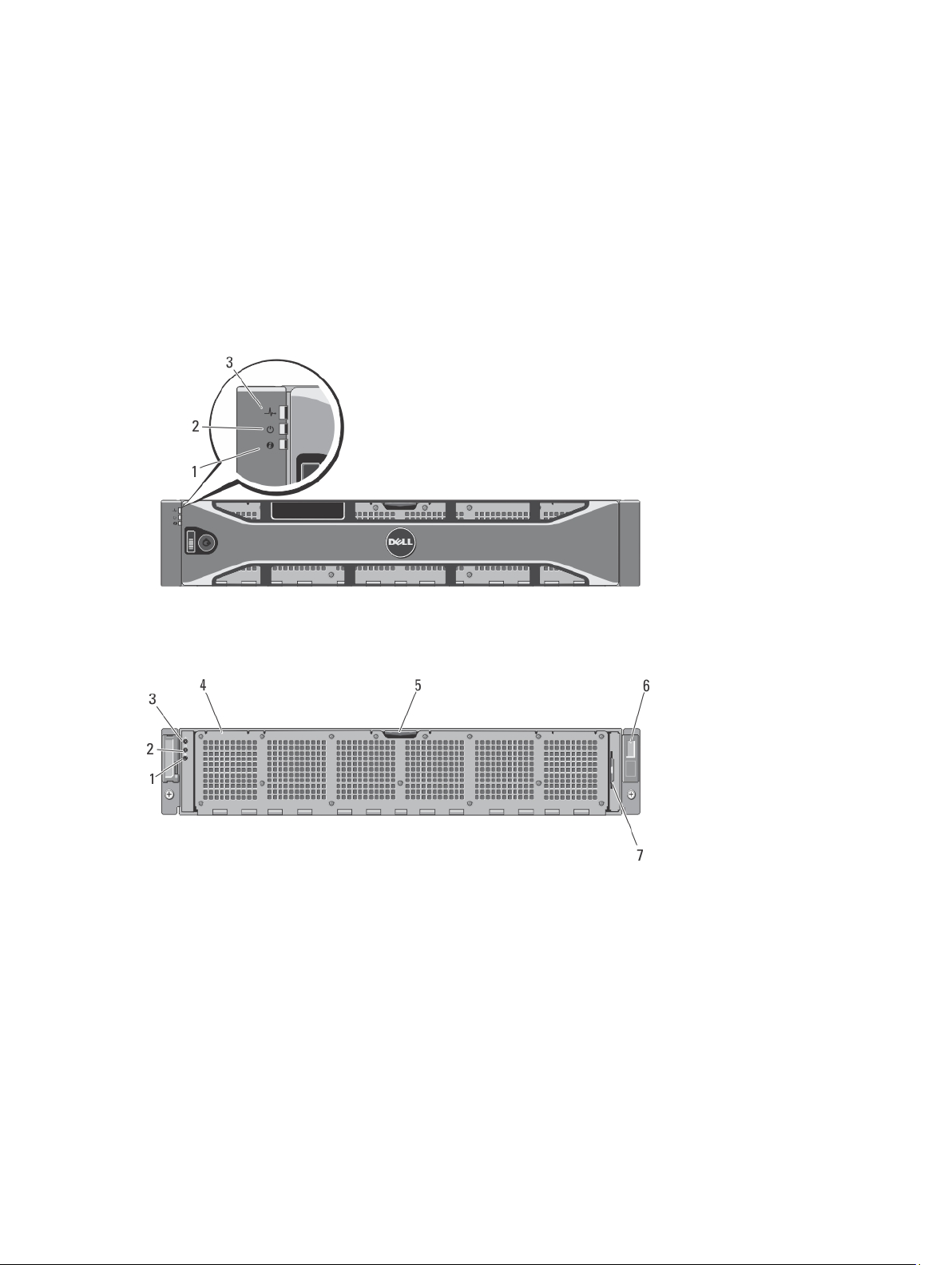
Front-Panel Features And Indicators
Figure 1. Front Bezel Indicators
1
Figure 2. Front-Panel Features and Indicators
5
Item Indicator, Button, or
Connector
1 System identification button The identification buttons on the front and back panels
2 Power-on indicator The power LED lights green when at least one power
3 System health indicator The system status LED lights only when the system power
4 Cooling-fan access door Encloses and protects the hot-swappable cooling fans.
Icon Description
can be used to locate a particular system within a rack.
When one of these buttons is pressed, the system status
indicator on the back flashes until one of the buttons is
pressed again. Press to toggle the system ID on and off.
supply is connected to a power source and is supplying
power to the system.
is on.
• Lights blue during normal operation.
• Blinks amber when one of the controllers is
reporting hardware errors, battery errors, or if
one controller is missing.
5 Cooling-fan access door
release latch
6 Service tag Displays the appliance service tag information.
7 Information tag A slide-out label panel listing the system NIC and BMC
Press the access door release latch to expose the hotswappable cooling fans.
MAC addresses for both controllers.
Back-Panel Features And Indicators
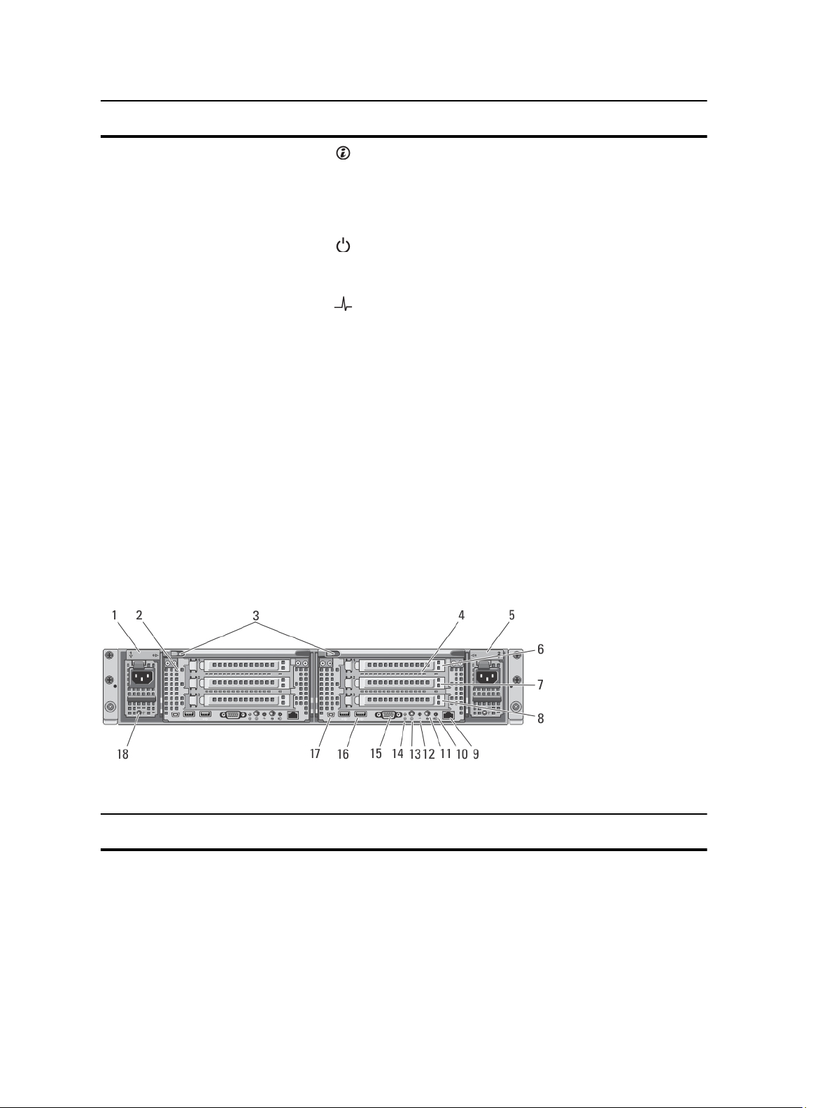
Figure 3. Back-Panel Features and Indicators
Item Indicator, Button, or
Connector
Icon Description
1 Power supply (PSU1) 717 W
2 Controller 1 Redundant NAS processing unit.
6

Item Indicator, Button, or
Connector
3 Release button Press the release button to disengage the controller
4 Controller 2 Redundant NAS processing unit.
5 Power supply (PSU2) 717 W
Icon Description
handle and remove the storage controller from the NAS
appliance chassis.
6 PCIe expansion card slot
(slot 1)
7 PCIe expansion card slot
(slot 2)
8 PCIe expansion card slot
(slot 3)
9 Ethernet connector Reserved for future use.
10 Cache active/off-load LED Lights when the storage controller contains cache and
11 System identification button The identification buttons on the front and back panels
12 System health indicator The system status LED lights only when the system power
Contains the pre-installed expansion card based on your
solution.
Contains the pre-installed expansion card based on your
solution.
Contains the pre-installed expansion card based on your
solution.
when the cache is being transferred from the memory to
the hard drive.
For more information on the cache activity LED indicator
codes, see Cache Activity LED Indicator Codes.
can be used to locate a particular system within a rack.
When one of these buttons is pressed, the system status
indicator on the back flashes until one of the buttons is
pressed again. Press to toggle the system ID on and off.
is on.
• Lights blue during normal operation.
• Blinks amber when one of the controllers is
reporting hardware errors, battery errors, or if one
controller is missing.
13 Power-on indicator, power
button
The power-on indicator lights when the system power is
on. The power button controls the power supply output to
the system.
• When the controller is powered on, if you press
and release the power button the controller
performs a graceful shutdown.
• When the controller is off, if you press and release
the power button, the controller powers on.
NOTE: Pressing and holding the power button for
several seconds will not shutdown the controller
immediately .
For more information on the power button indicator codes,
see Power-Button LED Indicator Codes.
7
Item Indicator, Button, or
Connector
14 Service action button Used to troubleshoot certain errors. This button can be
15 Video connector Allows you to connect a VGA display to the system.
16 USB connectors (2) Allows you to connect USB devices to the system. The
Icon Description
pressed using the end of a paper clip.
NOTE: You must press and hold the button for ten
seconds to generate an SCI interrupt.
NOTE: Use this button only if directed to do so by
qualified support personnel.
ports are USB 2.0-compliant.
17 Serial COM port (mini USB
connector)
18 PSU indicator Indicates whether power is present or whether a power
Allows you to connect a serial device to the system.
NOTE: This connector is for service only. Connect to
this connector only if asked to do so by Dell support.
fault has occurred.
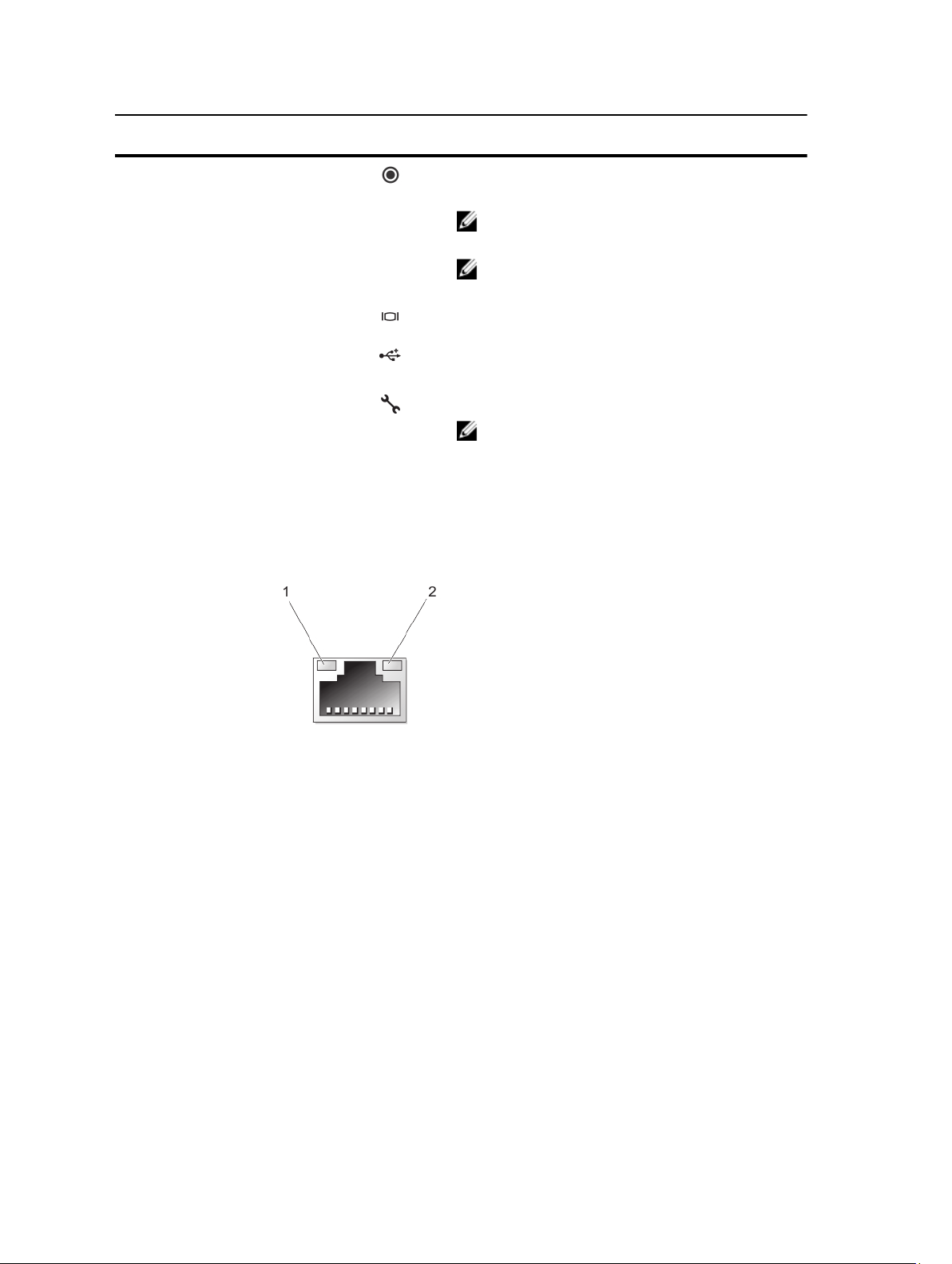
NIC Indicator Codes
Figure 4. NIC Indicator
1. link indicator
2. activity indicator
Indicator Indicator Code
Link and activity indicators are off The NIC is not connected to the network.
Link indicator is green The NIC is connected to a valid network at its maximum port speed (1 Gbps or 10
Gbps).
Link indicator is amber The NIC is connected to a valid network at less than its maximum port speed.
Activity indicator is blinking green Network data is being sent or received.
8
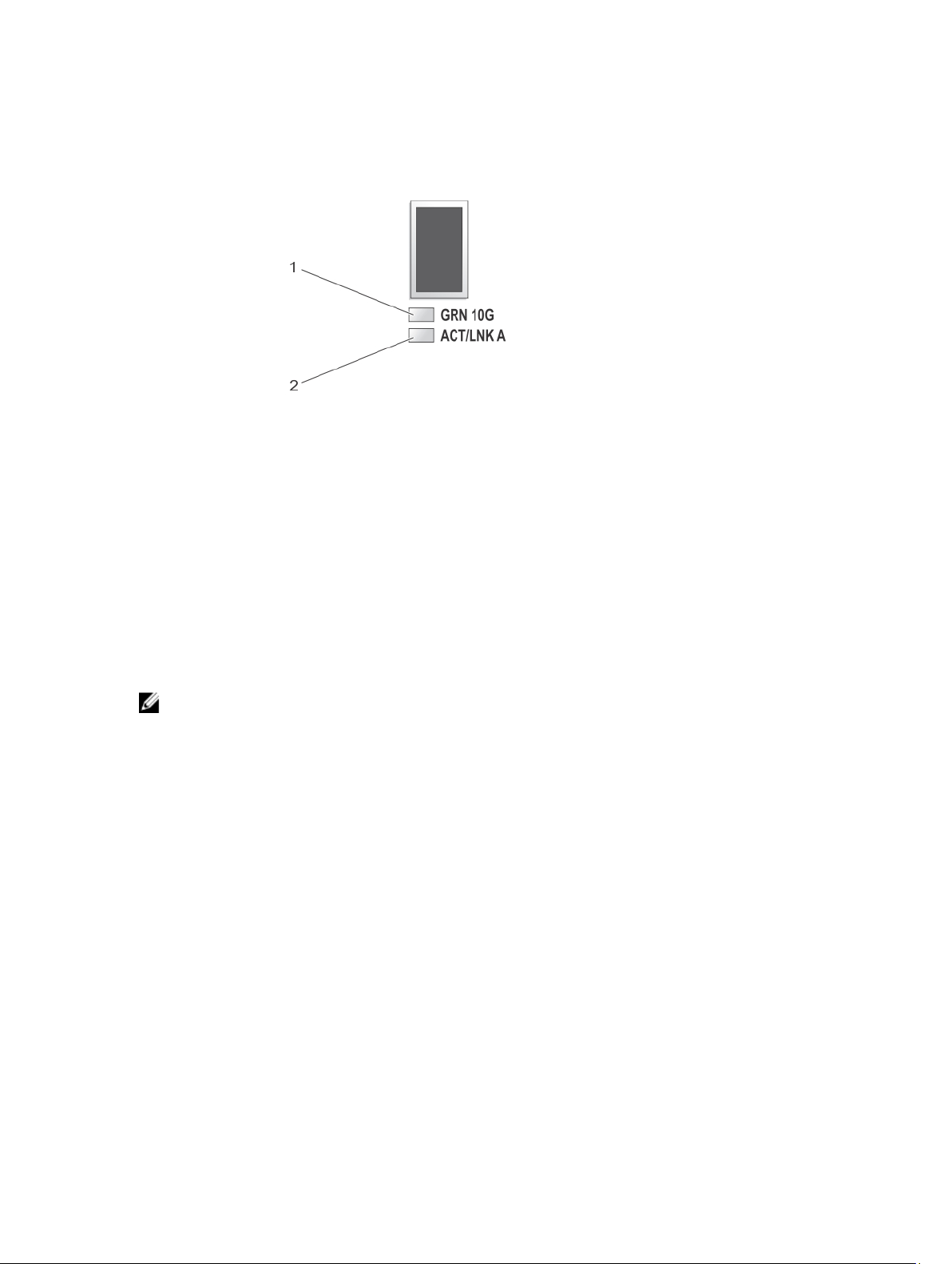
SFP+ Indicators
Figure 5. SFP+ Indicators
1. link indicator
2. activity indicator
Indicator Description
Link and activity indicators are off The SFP+ module is not connected to the network.
Link indicator is green The SFP+ module is connected to a valid network.
Activity indicator is blinking green Network data is being sent or received.
Fibre Channel LED Indicators
NOTE: This fibre channel LED indicator codes are specific only to the Dell Compellent FS8600 NAS Solution.
9
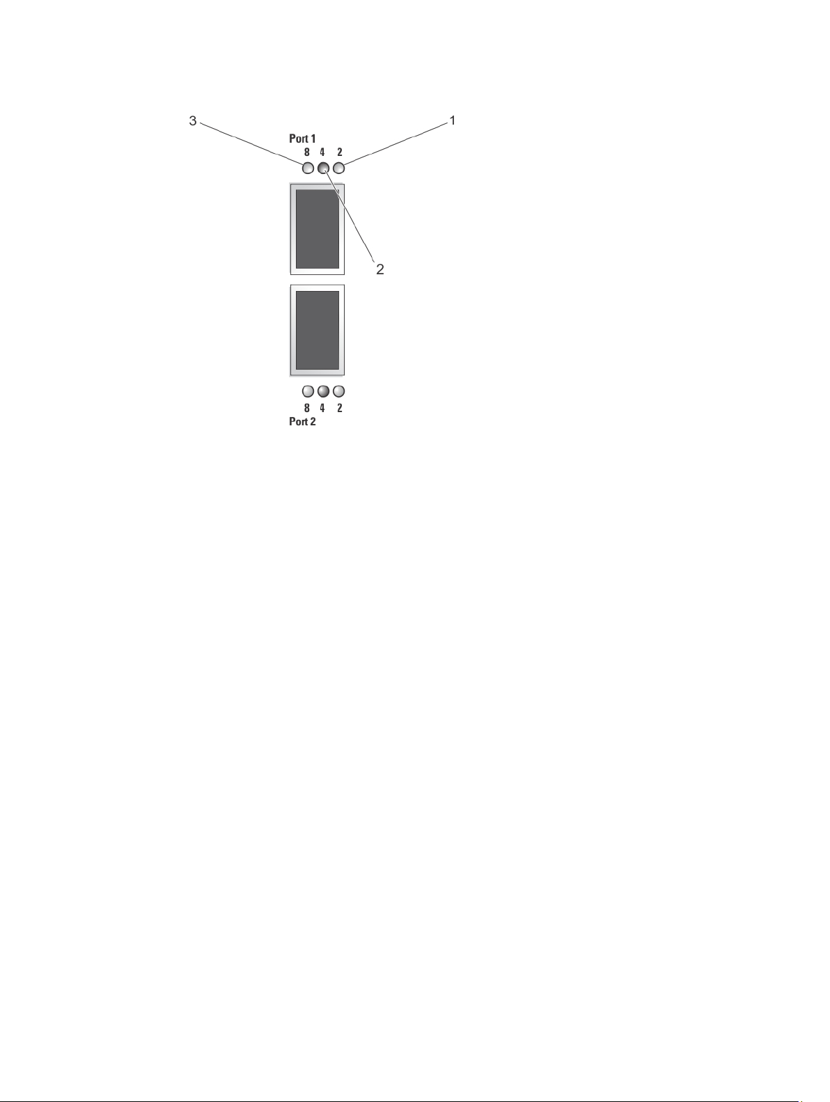
Figure 6. fibre Channel Indicators
1. Amber LED (2 Gbps)
2. Green LED (4 Gbps)
3. Yellow LED (8 Gbps)
Indicator Description
All LEDs off Indicates that there is no power connected to the host bus adapter.
All LEDs on Indicates that the power is connected to the host bus adapter and that the
firmware is not initialized.
All LEDs flashing Indicates that the power is connected to the host bus adapter and that the
firmware is initialized.
Yellow, Green, and Amber LEDs
Indicates a firmware error.
flashing alternately
Amber LED on Indicates that the host bus adapter is online with a 2 Gbps link.
Amber LED flashing Indicates I/O activity on a 2 Gbps link.
Green LED on Indicates that the host bus adapter is online with a 4 Gbps link.
Green LED flashing Indicates I/O activity on a 4 Gbps link.
Yellow LED on Indicates that the host bus adapter is online with an 8 Gbps link.
Yellow LED flashing Indicates I/O activity on an 8 Gbps link.
10
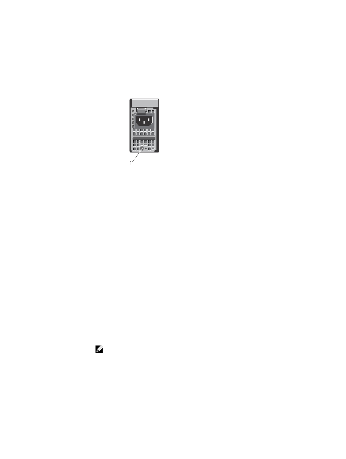
Power Indicator Codes
Power Supply Unit LED Indicator Codes
Each AC power supply has an LED that serves as an indicator to show whether power is present or whether a power
fault has occurred.
Figure 7. AC Power Supply Status Indicator
1. AC power supply status indicator
Power Indicator Pattern Condition
Off Power is not connected.
Green Indicates that a valid power source is connected to the power supply and that the power
supply is operational.
Flashing amber Indicates a problem with the power supply.
Power-Button LED Indicator Codes
The controller has a power-button LED on the back of the chassis. The power-button LED serves as an indicator to show
if power is present, if a power fault has occurred, or if the controller is running on backup power supply.
Indicator Description
Off Indicates that the controller is in power off mode.
Solid amber Indicates that the controller is powered on and about to enter system power-on self test (POST).
If the controller is not responding, it indicates that the controller may have a hardware failure
that is not allowing the controller to get to BIOS POST.
Slow blink amber Indicates that the controller is currently in BIOS POST or option ROM load stage.
NOTE: The LED flashes once every two seconds.
If the controller is not responding, it may indicate that a failure has occurred in POST or option
ROM load phase.
Slow blink green Indicates that the controller is attempting to start the operating system.
11
Indicator Description
NOTE: The LED flashes once every two seconds.
If the controller is not responding, it may indicate that the operating system did not load correctly.
Solid green Indicates that the controller is clustered and fully functional.
Fast blink green Indicates that the controller is in standby state and waiting to be clustered.
NOTE: The LED flashes five times every second.
Fast blink amber Indicates that the controller is currently in battery mode.
NOTE: The LED flashes five times every second.
NOTE: The controller may run in battery mode for up to 20 to 30 mins with a new battery.
Blink alternating
amber/green
Indicates that there is a hardware mismatch or the expected hardware configuration does not
match the actual hardware configuration. For example, an eight-core processor is expected, but
only a four-core processor is detected on the system.
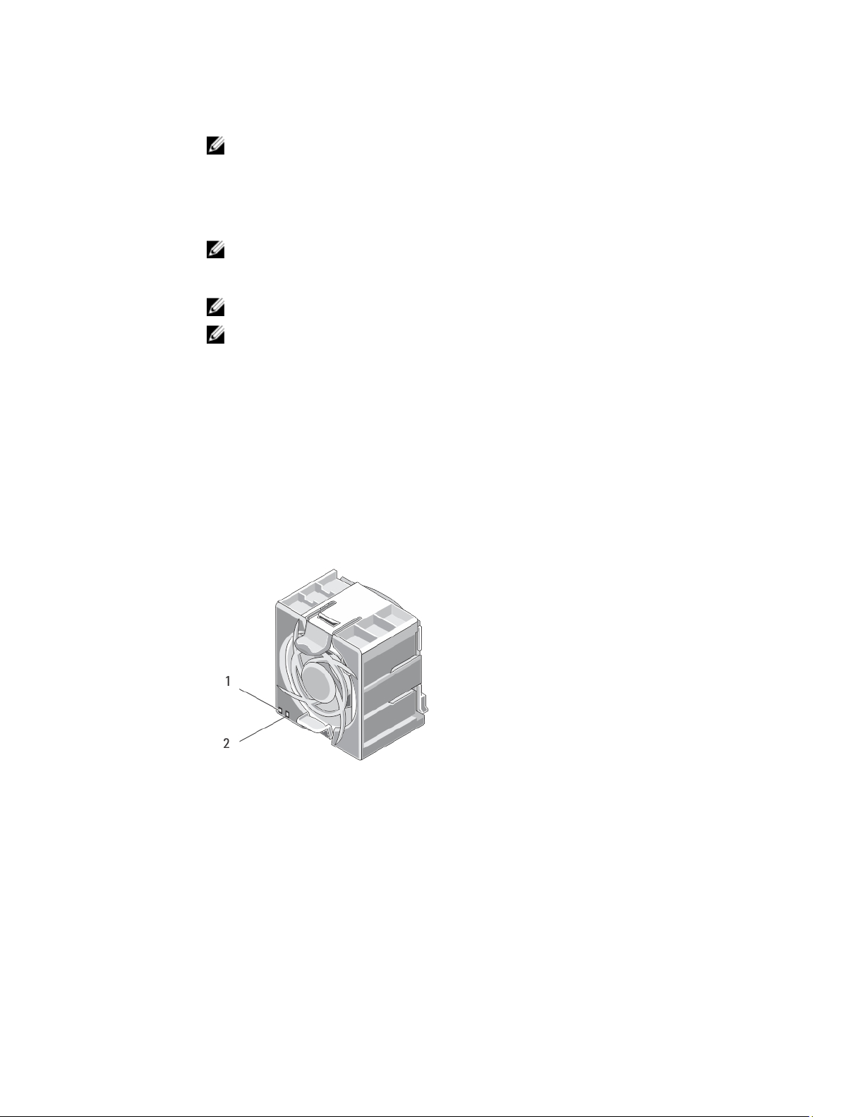
Cooling Fan LED Indicator Codes
Each cooling fan has two LEDs:
• Power LED
• Status LED
Figure 8. Cooling Fan Indicators
1. power LED
2. status LED
12
Power LED Indicator Codes
Indicator Description
Off Indicates that no power is available to the fan.
Solid green Indicates that the power is on.
Status LED Indicator Codes
Indicator Description
Off Indicates normal operating state.
Blinking amber Indicates system fault or error condition.
Cache Activity LED Indicator Codes
The cache activity LED lights when the storage controller contains cache and when the cache is being transferred from
the memory to the hard drive.
Indicator Indicator Codes
Off Indicates that there is no write data in the cache. It is safe to remove the controller when the cache
activity LED is off.
Solid green Indicates that it is safe to remove the controller without loss of cached data. It is safe to remove one
controller but not both the controllers.
Flashes amber Indicates that cache is being transferred from the memory to the hard drive (moving from mirroring
mode to journaling mode).
CAUTION: Removing the controller from the NAS appliance when the cache LED indicator is
flashing amber causes loss of data.
Other Information You May Need
WARNING: See the safety and regulatory information that shipped with your system. Warranty information may be
included within this document or as a separate document.
• The
Getting Started Guide
• The rack documentation included with your rack solution describes how to install your system into a rack, if
required.
• The
Administrator's Guide
manager.
• The
Deployment Guide
appliance.
• The
System Placemat
• Any media that ships with your system that provides documentation and tools for configuring and managing your
system, including those pertaining to the operating system, system management software, system updates, and
system components that you purchased with your system.
provides an overview of setting up your system and technical specifications.
provides an overview of the tasks that must be completed to configure the NAS
provides information on hardware deployment and the initial deployment of the NAS
provides information on how to rack your system.
13

• For the full name of an abbreviation or acronym used in this document, see the Glossary at support.dell.com/
manuals.
NOTE: Always check for updates on support.dell.com/manuals and read the updates first because they often
supersede information in other documents.
14
Installing System Components
Recommended Tools
You may need the following items to perform the procedures in this section:
• Key to the system keylock
• #2 Phillips screwdriver
• T8 and T15 Torx screwdrivers
• Wrist grounding strap connected to ground
Front Bezel
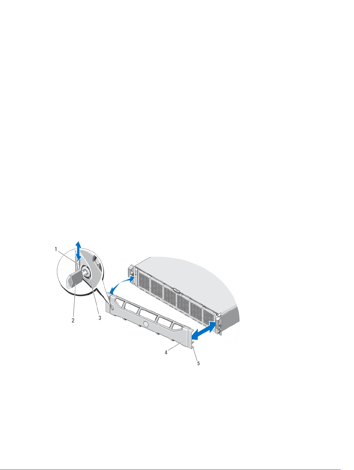
Installing The Front Bezel
1. Hook the right end of the bezel onto the chassis.
2. Fit the free end of the bezel onto the chassis.
3. Secure the bezel with the keylock.
2
Figure 9. Removing and Installing the Front Bezel
1. release latch
2. key
3. keylock
15
 Loading...