

Page 1
Setting Up Your PowerVault Network Attached Storage Solution
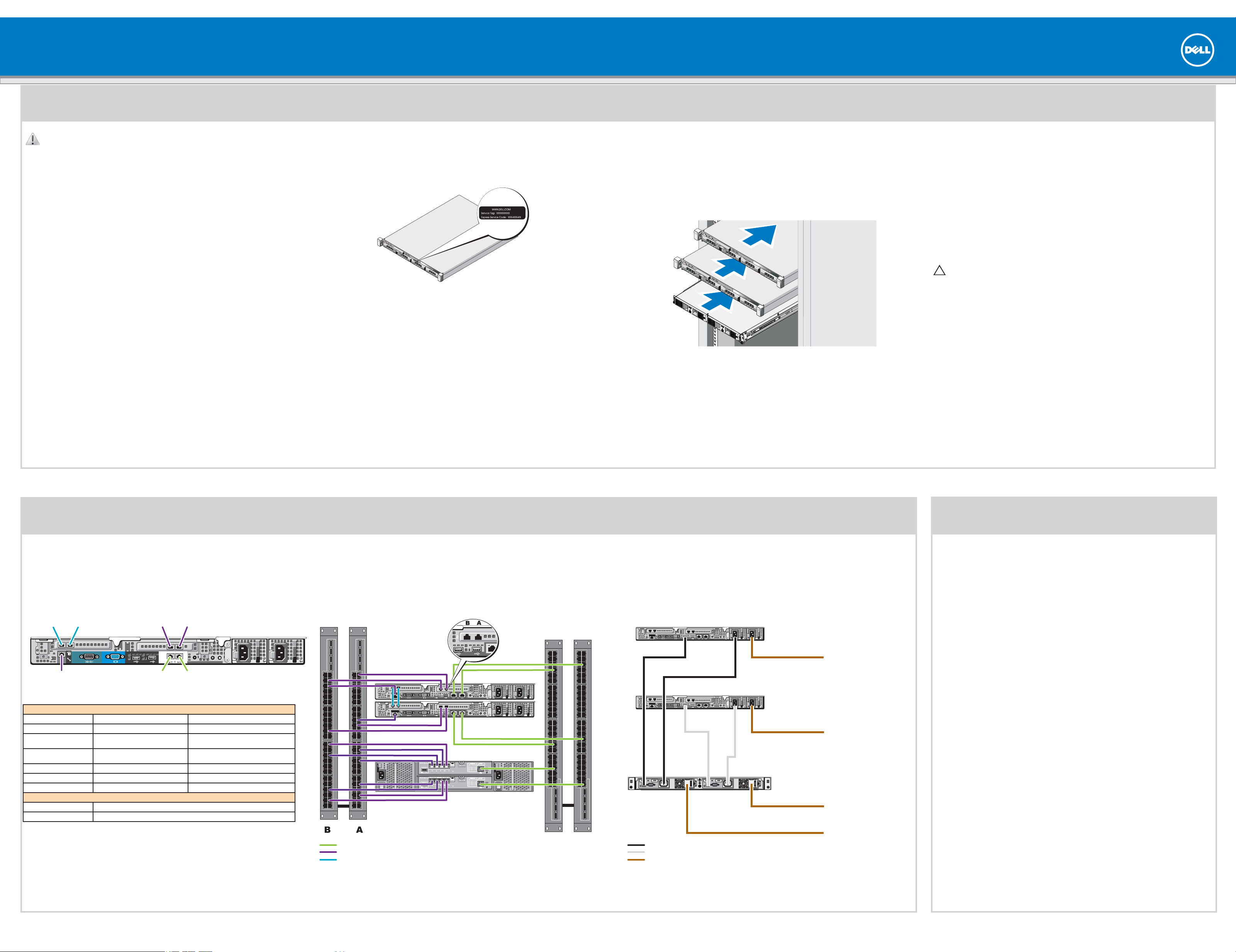
1 | Racking Your Solution
WARNING: Before you set up and operate your Dell PowerVault system, review
the safety instructions that shipped with your system.
Read the Dell Software License Agreement
Before using your system, please read the Dell Software License Agreement that •
came with the system.
If you do not accept the terms of the agreement, please call the customer •
assistance telephone number. For customers in the United States,
call 800-WWW-DELL (800-999-3355). For customers outside the United States,
visit support.dell.com and select your country or region from the top of the page.
Verifying Package Contents
Verify that all components listed on your packing slip are available. Save all
documentation and accessories.
Locating Your System Service Tag
Your system is identified by a unique Express Service Code and Service Tag number. •
The Express Service Code and Service Tag are found on the front of the system by
pulling out the information tag.
This information is used by Dell to route support calls to the appropriate personnel.•
Installing the Solution in a Rack
The solution requires a properly grounded electrical outlet, a compatible rack, •
and a rack installation kit.
For information about installing the rails for the PowerVault NX3500 system, •
see the
For information about installing rails for the backup power supply, •
see the
Rack Installation Instructions
that shipped with your rail kit.
Dell PowerVault NX3500 Getting Started Guide.
Installation Guidelines
The PowerVault NX3500 hardware configuration consists of two PowerVault •
NX3500 controller units and one backup power supply (BPS) unit. The BPS
is required even if you have an uninterruptible power supply system in your
environment. Install the three hardware components adjacent to one another in
the same rack.
Depending on your configuration, use 18 or 22 Category 5E or Category 6 Ethernet •
cables with RJ45 connectors. Connect 14 cables to the PowerVault NX3500
controllers and four or eight cables to the MD storage array.
It is recommended that you use a minimum of four network switches as shown in •
step 2.
Connecting the Battery in the Backup Power Supply
CAUTION: Always verify the voltage rating of the backup power supply.
Connecting a 230 VAC into a 120 V back up power supply damages the backup
power supply.
Remove the power module front cover.1.
Remove the battery from the power module.2.
Rotate the battery 180 degrees.3.
Reinstall the battery in the power module.4.
Repeat step 2 to step 4 of this procedure for the second battery.5.
Attach the power module front cover.6.
2 | Cabling Your Solution
Planning
Proper planning is essential to successfully deploy the PowerVault NX3500 solution. This placemat contains one scenario using two redundant iSCSI switches. If your SAN is configured in a different configuration, see the
It is recommended that you complete the IP chart in step 4 prior to deploying the solution. The IP chart is also available in the
Cabling Worksheet
Peer
connection
0
Internal connection
to SAN switch
PowerVault NX3500 Controller 0 Controller 1
Client connection 1 To client switch To client switch
Client connection 2 To client switch To client switch
Peer connection 0 Back to back (peer connection 0 to peer
Peer connection 1 Back to back (peer connection 1 to peer
SAN connection A To SAN switch (A) To SAN switch (B)
SAN connection B To SAN switch (B) To SAN switch (A)
Internal connection To SAN switch (B) To SAN switch (A)
PowerVault MD Storage Array Connection
Port 0 To SAN switch (A)
Port 1 To SAN switch (B)
Peer
connection
1
connection
connection
connection 0)
connection 1)
SAN
B
Client
1
SAN
connection
A
Client
connection
2
Back to back (peer connection 0 to peer con-
Back to back (peer connection 1 to peer con-
nection 0)
nection 1)
Network Cabling
SAN switches
Administrator’s Guide
PowerVault NX3500 contoller 0
PowerVault NX3500 contoller 1
PowerVault MD storage array
. It is also recommended that you set your switch MTU size to 9000 or greater and enable Spanning Tree Portfast and flow control.
Power Cabling
Client switches
USB
PowerVault NX3500 controller 0
Power
PowerVault NX3500 controller 1
USB
Administrator’s Guide
Power
Backup power supply
for additional cabling options.
To power source 1
To power source 2
To power source 1
3 | Turning On Your Solution
Verify that your network environment and modular disk storage arrays are turned on.
Turn on the components in the following order:
Dell backup power supply1.
Dell PowerVault NX3500 controllers2.
Client connections
Internal network and SAN connections
Peer connections
To power source 2
PowerVault NX3500 controller 0
PowerVault NX3500 controller 1
To the grid
Page 2
Setting Up Your PowerVault Network Attached Storage Solution
4 | Preparing Your Environment for the PowerVault NX3500 Solution
(continued)
IP Chart
The IP chart helps you plan your confi guration. Recording the IP addresses of your solution in a single location enables you to confi gure your setup faster and more effi ciently.
NAS Appliance Setup Worksheet
PowerVault NAS Confi guration
Utility Confi guration
Info Requested Value IP Function IPs Allocated Sample IPs Physical
Storage Array Identifi cation Subnet 1 - Primary Network
MD Discovery IP
MTU NAS Management VIP
NX3500 Controller Discovery Controller 0 IP
Controller 0 MAC Address Controller 1 P
Controller 1 MAC Address Subnet Mask
NAS Appliance Identifi cation
NAS Cluster Name Subnet 2 - Internal/Private Network Group 1
NAS Controller 0 IQN Internal IP a2
NAS Controller 1 IQN Internal IP a3
Use the IQNs recorded from the PowerVault
NAS Confi guration Utility to complete your
mappings confi guration on the MD3x00i
backend storage
. . .
PowerVault NAS Confi guration
Utility Results
Client Access VIP
Gateway
Internal IP a0
Internal IP a1
Subnet Mask
NAS Cluster IP Allocation
. . .
. . .
. . .
. . .
. . .
. . .
. . .
. . .
. . .
. . .
. . .
10.10.1.100 Client
10.10.1.200 Client
10.10.1.201 Client
10.10.1.202 Client
255.255.255.0 Client
10.10.1.1 Client
172.168.1.1 Internal/Peer
172.168.1.2 Internal/Peer
172.168.1.3 Internal/Peer
172.168.1.4 Internal/Peer
255.255.255.0 Internal/Peer
Connections
Environment Setup Checklist NAS Cluster IP Allocation
Management Station
Verify IPv6 enabled•
Install PowerVault NAS Confi guration Utility•
Switch Topology
Determine desired switch topology from one
of the following confi gurations:
All-in-one•
All-in-one high availability•
Optimal•
Optimal high availability•
NAS Appliance Setup Worksheet - continued
IP Function IPs Allocated Sample IPs Physical
Subnet 3 - Internal/Private Network Group 2
Internal IP b0
Internal IP b1
Internal IP b2
Internal IP b3
Subnet Mask
Subnet 4 - SAN Network Group 1
SANa IP 0
SANa IP 1
Subnet Mask
Subnet 5 - SAN Network Group 2
SANb IP 0
SANb IP 1
Subnet Mask
. . .
. . .
. . .
. . .
. . .
. . .
. . .
. . .
. . .
. . .
. . .
172.168.2.1 Internal/Peer
172.168.2.2 Internal/Peer
172.168.2.3 Internal/Peer
172.168.2.4 Internal/Peer
255.255.255.0 Internal/Peer
192.168.10.20 SAN (to
192.168.10.21 SAN (to
255.255.255.0
192.168.11.20 SAN (to
192.168.11.21 SAN (to
255.255.255.0
Connections
Switch A)
switch A)
switch B)
switch B)
PowerVault MD Confi guration
IP Function IPs Allocated Sample IPs Physical
Controller 0 Port 0 IP
Controller 0 Port 1 IP
Controller 0 Port 2 IP
Controller 0 Port 3 IP
Controller 1 Port 0 IP
Controller 1 Port 1 IP
Controller 1 Port 2 IP
Controller 1 Port 3 IP
. . .
. . .
. . .
. . .
. . .
. . .
. . .
. . .
192.168.10.100 SAN (to
192.168.11.100 SAN (to
192.168.12.100
192.168.13.100
192.168.10.101 SAN (to
192.168.11.101 SAN (to
192.168.12.101
192.168.13.101
Connections
switch A)
switch B)
switch A)
switch B)
Terms Used In the IP Chart
Controller—A server appliance installed with the Dell scalable fi le system software. An
essential component of a PowerVault NAS clustered solution.
Internal IP—IP address used for internal operations between the NAS controllers and the
storage subsystem.
SAN network/iSCSI network—The network that carries the block level (iSCSI) traffi c and
to which the storage subsystem is connected. It is recommended that this network be
separated from the client network.
NAS cluster name—The name that is used to identify the PowerVault NX3500
solution.
NAS management VIP—IP addresses that the management stations use to access the
PowerVault NX3500 controllers.
Client access VIP—IP address that clients use to access CIFS shares and NFS exports
hosted by a PowerVault NAS solution. The PowerVault NAS solution supports multiple
client access VIPs.
MD discovery IP—The MD discovery IP is an MD storage array (iSCSI) IP address from
either the SAN A or SAN B network.
Preparing the Management Station
Connect the management station to the client switch.•
Verify that IPv6 is enabled.•
Verify that Java (JRE) is installed on the management station.•
Install the • PowerVault Confi guration Utility software.
Download SSH client for CLI access.•
Preparing the Modular Disk Storage Arrays
Create a disk group for each virtual disk.1.
Create a virtual disk in each disk group. Virtual disks must be created and assigned 2.
to the host group in pairs. A minimum of 2 virtual disks is required and a maximum
of sixteen is supported. Each pair of virtual disks must be of the same size. For more
information, see the
Create a host group. For example, name host group 3.
Map the virtual disks to the host group.4.
NOTE: Additional confi guration is required after completing the steps in the
PowerVault Confi guration Utility. For more information, see step 5.
Administrator’s Guide
.
PV-NX3500
.
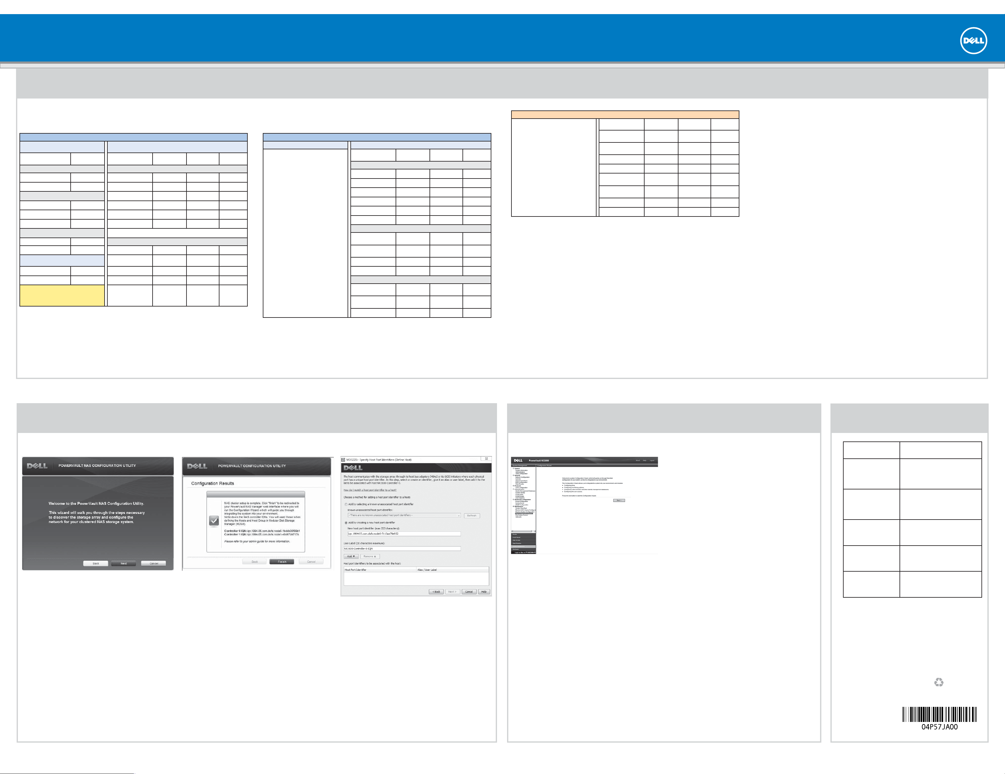
5 | Confi guration Utility and Modular Disk Storage Manager Client
Launching the Confi guration Wizard
From the management station, launch the PowerVault
Confi guration Utility and follow the instructions on the
screen.
The PowerVault Confi guration Utility guides you through
the network confi guration and enables you to set up and
access the PowerVault NX3500 controllers on the
management station.
Completing Your Setup
Copy the IQN numbers from the 1. Confi gurations
Results screen without closing the screen.
Launch the 2. Modular Disk Storage Manager Client and
click the Mappings tab.
In the 3. Mappings screen, right-click the host group
and select Defi ne→ Host. Enter a host name and click
Next.
For example,
PV-NX3500-Controller-0
4. On the second screen, type the IQN for the controller
and provide a user label. The user label must not be
the same as the host name. It is recommended that
you use the host name appended with -IQN.
For example,
PV-NX3500-Controller-0-IQN
Repeat step 3 and step 4 for controller 1.5.
Close the 6. Modular Disk Storage Manager Client.
In the 7. Confi guration Results screen, click Finish.
6 | System Confi guration 7 | Documentation
The PowerVault NX3500 web interface provides
information about the controller and guides you
through the steps necessary to confi gure the network
for your clustered NAS solution. The web interface
automatically launches after you complete the
PowerVault Confi guration Wizard.
NOTE: If your web browser does not display the
PowerVault NX3500 web interface, check the security
settings of the web browser, accept the security
certifi cate, and ensure that JavaScript is enabled.
To access the PowerVault NX3500 web interface at a
later time, type the following URL in your web browser
https://<NAS Management VIP>.
Default User Name and Password
The default user name for the solution is admin
The default password for the solution is Stor@ge!
To complete the system confi guration, complete the
following steps in the PowerVault NX3500 web interface:
Configuring DNS •
Configuring time •
Configuring e-mail •
Configuring SNMP•
Setting up file system•
Changing the administrator password•
Configuring system identity•
Configuring identity management•
Configuring cross protocol •
Creating NAS volumes•
Creating CIFS shares•
Creating NFS exports•
Title
Getting Started Guide
Hardware Owner’s Manual
Rack Installation Instructions
Administrator’s Guide
Online Help
Information in this publication is subject to change without notice.
© 2011 Dell Inc. All rights reserved.
Reproduction of these materials in any manner whatsoever without the written
permission of Dell Inc. is strictly prohibited.
Dell™, the DELL
Other trademarks and trade names may be used in this publication to refer to either
the entities claiming the marks and names or their products. Dell Inc. disclaims any
proprietary interest in trademarks and trade names other than its own.
logo, and PowerVault™ are trademarks of Dell Inc.
Description
The Getting Started Guide provides an
overview of system features, setting up your
solution, and technical specifi cations.
This document is shipped with your system
and is also available at support.dell.com/
manuals.
The Hardware Owner’s Manual provides
information about solution features and
describes how to troubleshoot the system
and install or replace system components.
This document is available at support.dell.
com/manuals.
The rack documentation included with your
rack solution describes how to install your
system into a rack. This document is shipped
with your rack solution and is also available
at support.dell.com/manuals.
The Administrator’s Guide provides
information about confi guring, managing,
and troubleshooting the software and the
solution. This document is available at
support.dell.com/manuals.
The Online Help provides information about
confi guring and managing the software.
The online help is integrated with the system
and can be accessed from the PowerVault
NX3500 web interface.
Printed in the U.S.A.
2011 - 08
 Loading...