

Page 1

Dell PowerVault NX3500
Systems
Getting Started With
Your System
Mise en route
Introdução ao uso do seu sistema
Introducción al sistema
Page 2

Page 3

Dell PowerVault NX3500
Systems
Getting Started With
Your System
Regulatory Model: E07S Series,
DELL500WLV, and DELL500WHV
Page 4
Notes, Cautions, Warnings, and Danger
NOTE:
A NOTE indicates important information that helps you make better use of
your computer.
CAUTION:
instructions are not followed.
WARNING:
personal
DANGER:
avoided, will result in death or serious injury.
A CAUTION indicates potential damage to hardware or loss of data if
A WARNING indicates a potential for property damage,
injury, or death.
A DANGER indicates an imminently hazardous situation which, if not
____________________
Information in this publication is subject to change without notice.
© 2011 Dell Inc.; Eaton Corporation. All rights reserved.
Reproduction of these materials in any manner whatsoever without the written permission of Dell Inc.
and Eaton Corporation is strictly forbidden.
Trademarks used in this text: Dell™, the DELL logo, and PowerVault™ are trademarks of Dell Inc.
®
Intel
and Xeon® are registered trademarks of Intel Corporation in the U.S. and other countries.
Other trademarks and trade names may be used in this publication to refer to either the entities claiming
the marks and names or their products. Dell Inc. disclaims any proprietary interest in trademarks and
trade names other than its own.
Regulatory Model: E07S Series, DELL500WLV, and DELL500WHV
January 2011 P/N PXV2H Rev. A00
Page 5
Installation and Configuration
DANGER:
hazardous situation which, if not avoided, will result in death or serious injury:
The backup power supply contains LETHAL VOLTAGES. All repairs and service
should be performed by AUTHORIZED SERVICE PERSONNEL ONLY. There are
NO
WARNING:
instructions that came with the system.
Unpacking the Solution
Unpack the solution and identify each item.
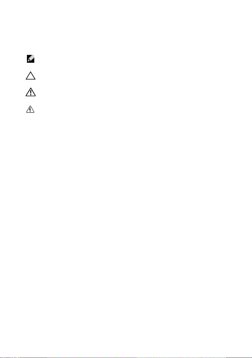
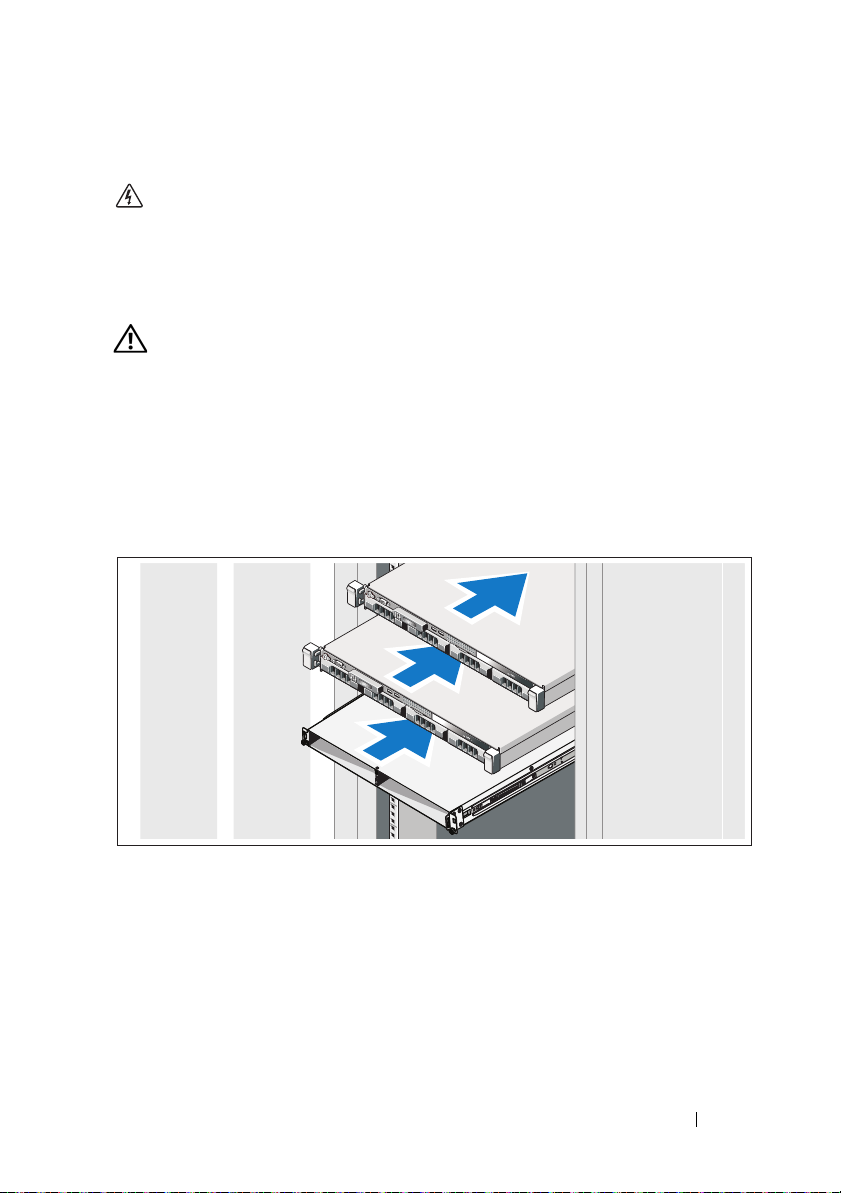
Installing the Rails, the System, and the Backup Power Supply in a Rack
Observe the following instruction to help prevent an imminently
USER SERVICEABLE PARTS inside the backup power supply.
Before performing the following procedure, review the safety
Assemble the rails and install the system and backup power supply (BPS) in the
rack. Follow the safety instructions and the rack installation instructions
provided with the solution.
Getting Started With Your System
3
Page 6
Connecting the Battery in the BPS Power Module
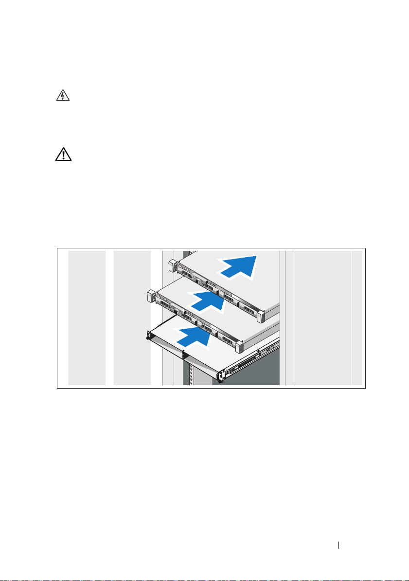
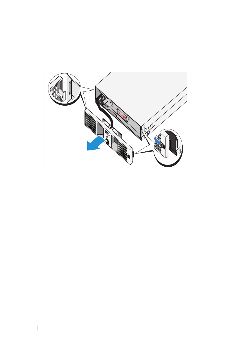
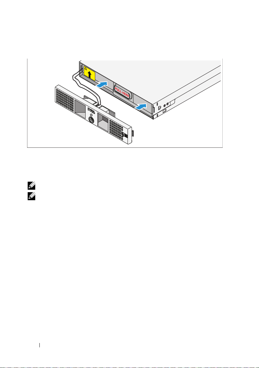
Removing the Power Module Front Cover
On the right side of the front cover, slide the latch to the left to retract the latch
hook. This hook secures the front cover to the right side of the chassis. Pull the
right side of the front cover from the chassis. Slide the front cover to the right to
disengage the hook. This hook secures the front cover to the left side of the chassis.
4
Getting Started With Your System
Page 7
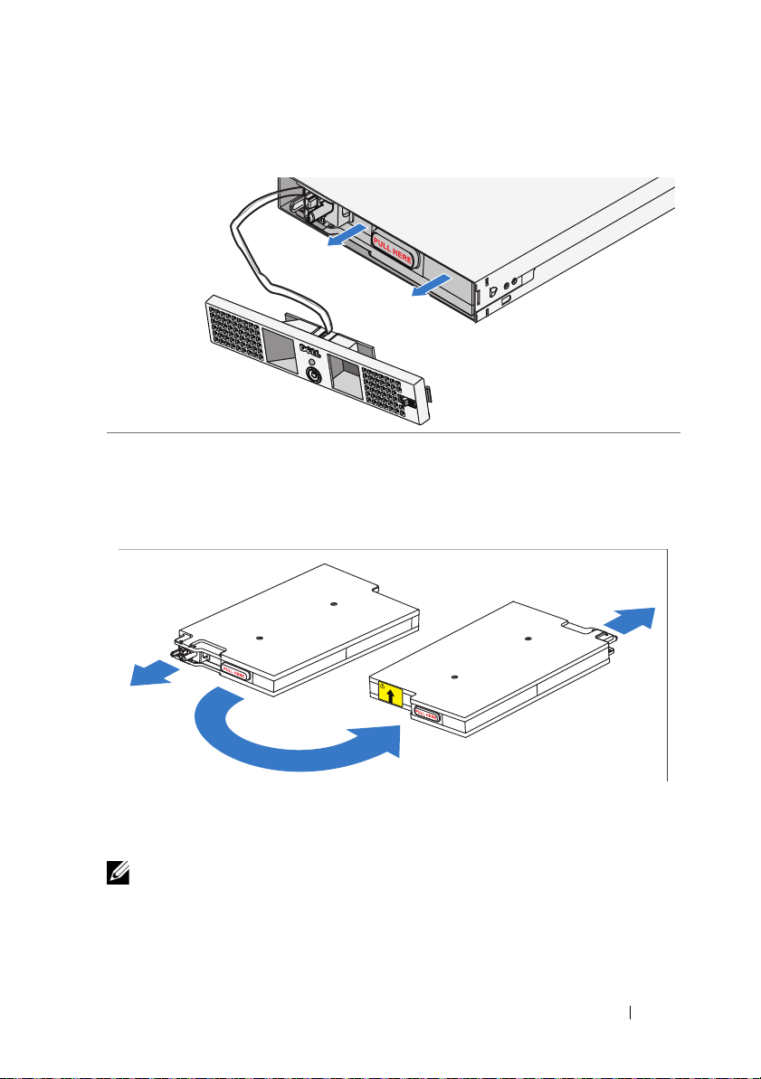
Removing the Battery
Pull the battery out of the power module.
Rotating the Battery
Rotate the battery 180° so the blind mate connector faces toward the back of
the power module chassis.
NOTE:
Ensure that the arrow on the yellow label is pointing up.
Getting Started With Your System
5
Page 8
Reinserting the Battery
Align the battery with the power module and reinsert the battery. Ensure that
the battery is fully seated in the power module. If the battery is not fully
inserted into the power module, the battery front cover will not close properly.
NOTE:
Always connect the battery pack before connecting the power cable.
NOTE:
You will not observe the blind mate connectors as they plug into the
receptacle in the back of the power module, but a small amount of arcing may
occur when connecting the battery pack. This is normal and does not damage the
unit or present any safety concern.
6
Getting Started With Your System
Page 9
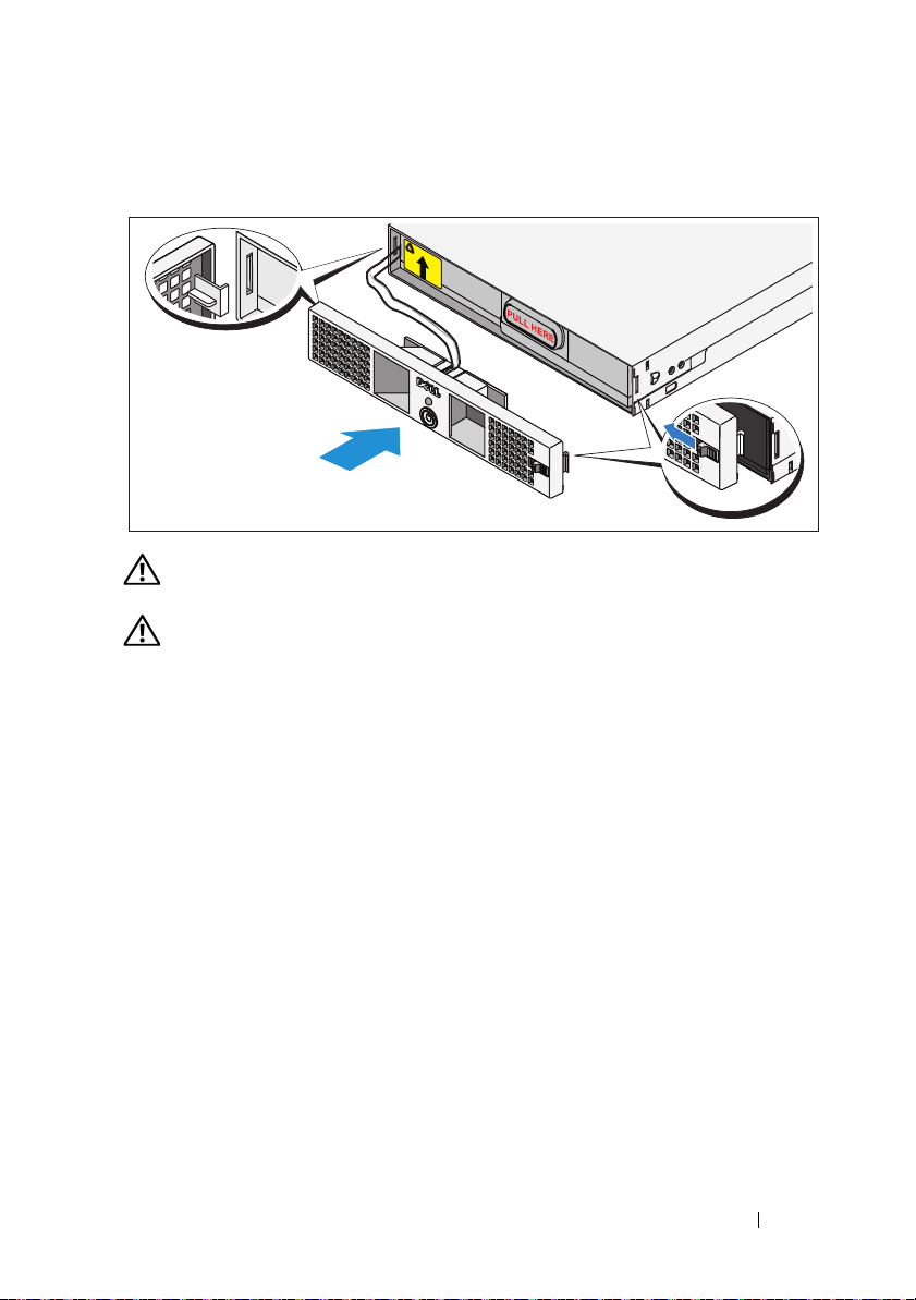
Securing the Power Module Front Cover
WARNING:
battery pack is inserted and connected.
WARNING:
module. For safety, do not allow the power module front cover to come in contact
with the battery pack.
For safety, always attach the power module front cover as soon as the
Align the front cover carefully before securing it to the power
On the left side of the first front cover, insert the hook into the open slot on the
left side of the chassis. On the right side of the front cover, slide the latch to the
left to retract the latch hook. Push the right side of the front cover forward to
the chassis. Release the latch to set the hook into the open slot on the right side
of the chassis.
Getting Started With Your System
7
Page 10
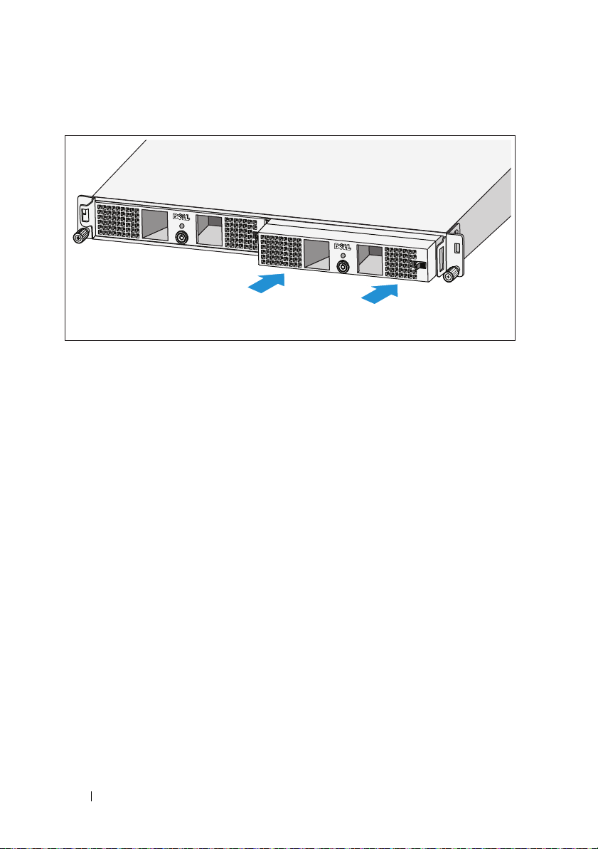
Inserting the Power Modules
Insert the power modules into the chassis module bay with the back panels
toward the back of the chassis.
8
Getting Started With Your System
Page 11
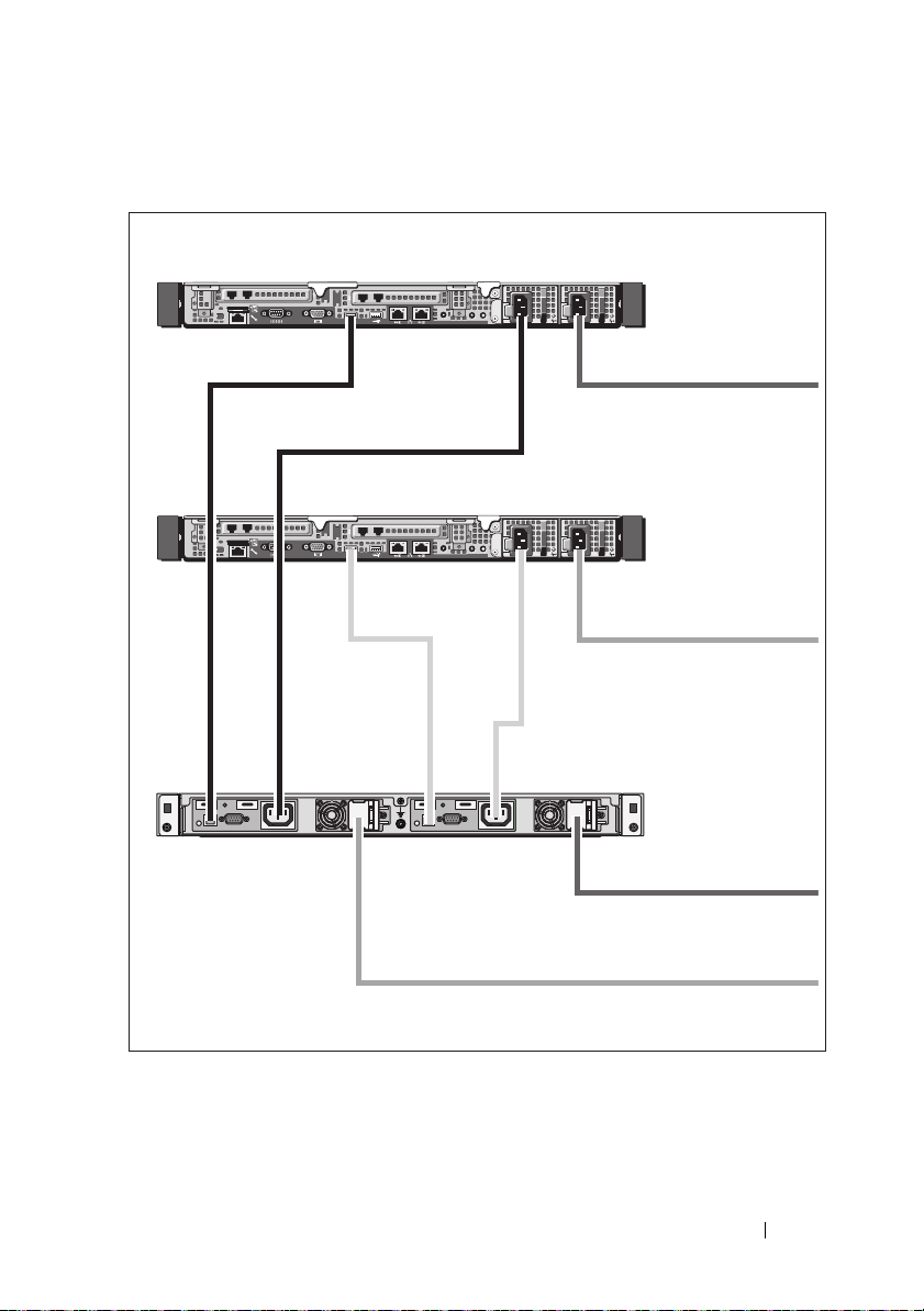
Cabling the Solution
PowerVault NX3500 system
PowerVault NX3500 system
Backup power supply
To power source 1
To power source 2
To power source 1
To power source 2
Cable the solution as shown in the illustration.
Getting Started With Your System
9
Page 12
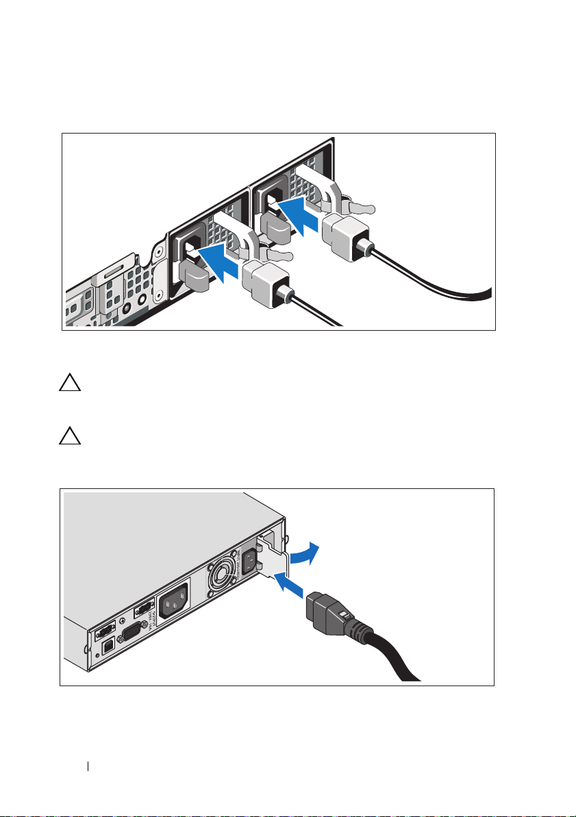
Connecting the Power Cable(s)
Connect the system’s power cable(s) to the system.
CAUTION:
C-13 output receptacles. Only use a power cord rated for the input power source
rating labeled next to the input connector on the power module back panel.
CAUTION:
Vac into a 120 V BPS will damage the BPS.
Both the 120 V (LV) and the 230 V (HV) power modules provide IEC 320
You must always verify the voltage rating of the BPS. Connecting a 230
Open the spring-loaded interlock cover for the input connector and connect the
power cable to the BPS.
10
Getting Started With Your System
Page 13
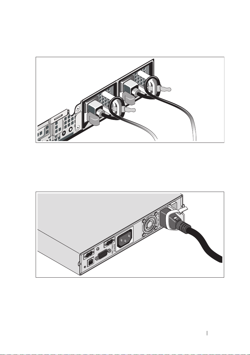
Securing the Power Cable(s)
Bend the system power cable(s) into a loop as shown in the illustration and
secure the cables to the brackets using the provided strap. Plug the other end of
one power cable to a grounded electrical outlet and the other cable to the BPS.
For more information, see "Cabling the Solution" on page 9.
Secure the power cable connected to the BPS as shown in the illustration.
Getting Started With Your System
11
Page 14
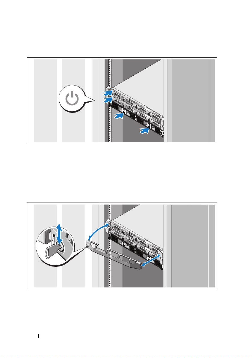
Turning On the Solution
Turn on the components in the following order:
1
The BPS
2
The PowerVault NX3500 systems
Installing the Optional Bezel
Install the bezel for the system (optional).
12
Getting Started With Your System
Page 15
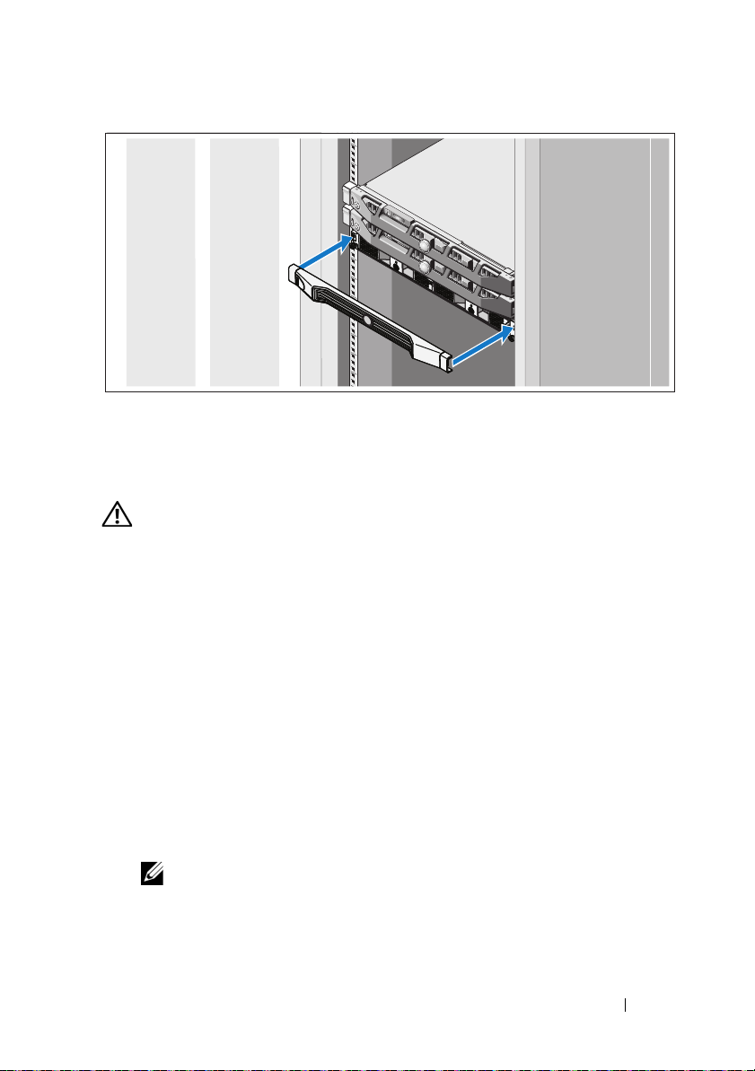
Install the bezel for the BPS (optional).
Other Information You May Need
WARNING:
system. Warranty information may be included within this document or
your
a separate document.
as
• The rack documentation included with your rack solution describes how to
install your system into a rack.
• The cable management arm instructions included with your rack solution
describes how to install the cable management arm into a rack.
• The
features and describes how to troubleshoot the system and install or
replace system components. This document is available online at
support.dell.com/manuals
• Any media that ships with your system that provides documentation and
tools for configuring and managing your
pertaining to the operating system, system management software, system
updates, and system components that you purchased with your system.
See the safety and regulatory information that shipped with
Hardware Owner’s Manual
provides information about system
.
system, including those
NOTE:
Always check for updates on support.dell.com/manuals and read the
updates first because they often supersede information in other documents.
Getting Started With Your System
13
Page 16
Obtaining Technical Assistance
If you do not understand a procedure in this guide or if the system does not
perform as expected, see your
comprehensive hardware training and certification. See
more information. This service may not be offered in all locations.
Hardware Owner’s Manual
. Dell offers
dell.com/training
for
NOM Information (Mexico Only)
The following information is provided on the device described in this document
in compliance with the requirements of the official Mexican standards (NOM):
Importer:
Model Number Supply Voltage Frequency Current Consumption
E07S 100–240 V CA 50/60 Hz 5.2–2.6 A
DELL500WLV 100–140 V CA 50/60 Hz 15 A
DELL500WHV 200–250 V CA 50/60 Hz 10 A
Technical Specifications
PowerVault NX3500 System Specifications
Processor
Processor type Intel Xeon processor 3400 series
Expansion Bus
Bus type PCI Express Generation 2
Expansion slots One x16 half-length slot
One x8 half-length slot
NOTE:
Both the slots support x8 routing.
14
Getting Started With Your System
Page 17

Memory
Architecture 1333-MHz registered parity and non registered
DDR-III memory modules
Memory module sockets Six 240-pin
Memory module capacities 2 GB
Maximum RAM 12 GB
Drives
Hard drives Two 3.5" hot-swappable SATA drives
Optical drive One internal slimline SATA DVD-ROM
NOTE:
DVD devices are data only.
Connectors
Back
NIC
Serial
USB
Video
Front
Video
USB
Internal
USB
Two RJ-45 (for integrated 1-GB NICs)
9-pin, DTE, 16550-compatible
Two 4-pin, USB 2.0-compliant
15-pin VGA
15-pin VGA
Two 4-pin, USB 2.0-compliant
Two 4-pin, USB 2.0-compliant
Video
Video type Matrox G200, integrated in BMC
Video memory 8 MB graphics memory
Getting Started With Your System
15
Page 18

Power
AC power supply (per power supply)
Wa t ta g e
Vo lt ag e
Heat dissipation
Maximum inrush current
Batteries
System battery
Physical
Height 4.29 cm (1.69 in)
Width 43.4 cm (17.09 in)
Depth 61.26 cm (24.12 in)
Weight (maximum configuration) 15 kg (33.02 lbs)
Weight (empty configuration) 5.96 kg (13.12 lbs)
Environmental
NOTE:
For additional information about environmental measurements for specific
system configurations, see dell.com/environmental_datasheets.
Te mp e ra t u re
Operating
Storage
400 W
100–240 VAC, 50/60 Hz
1666 BTU/hr maximum
Under typical line conditions and over the entire
system ambient operating range, the inrush
current may reach 25 A per power supply for
ms or less.
10
CR 2032 3.0-V lithium coin cell
10 °C to 35 °C (50 °F to 95 °F) with a maximum
temperature gradation of 10 °C per hour
NOTE:
For altitudes above 2950 feet, the maximum
operating temperature is derated 1 ºF/550 ft.
–40 °C to 65 °C (–40 °F to 149 °F) with
a
maximum temperature gradation of
°C per hour
20
16
Getting Started With Your System
Page 19

Environmental (continued)
Relative humidity
Operating
Storage
Maximum vibration
Operating
Storage
Maximum shock
Operating
Storage
Altitude
Operating
Storage
Airborne Contaminant Level
Class
8% to 85% (noncondensing) with a maximum
humidity gradation of 10% per hour
5% to 95% (noncondensing)
0.25 G at 3–200 Hz for 15 min
0.5 G at 3–200 Hz for 15 min
One shock pulse in the positive z axis (one pulse
on each side of the system) of 31 G for 2.6 ms
in
the operational orientation
Six consecutively executed shock pulses in
the
positive and negative x, y, and z axes
pulse on each side of the system) of 71 G
(one
for up to 2
–16 to 3048 m (–50 to 10,000 ft)
NOTE:
operating temperature is derated 1ºF/550 ft.
–16 to 10,600 m (–50 to 35,000 ft)
G1 as defined by ISA-S71.04-1985
ms
For altitudes above 2950 feet, the maximum
Backup Power Supply Specifications
BPS Model List
120 V Model Dell BPS 500 W (LV)
230 V Model Dell BPS 500 W (HV)
Getting Started With Your System
17
Page 20

Physical (120 V and 230 V Models)
Dimensions (Width x Height x
Depth)
Rack Unit Size 1 U
Weight 30.0 kg (66.1 lb)
Electrical Input
Nominal Voltage
120 V Model
230 V Model
Nominal Voltage Range
120 V Model
230 V Model
Nominal Frequency
120 V and 230 V Models
Efficiency (Normal Mode)
120 V and 230 V Models
Noise Filtering
120 V and 230 V Models
Connections
120 V and 230 V Models
434 mm x 42 mm x 723 mm (1.4 in x 0.1 in x
in)
2.4
NOTE:
Bezel depth 33 mm (0.1 in) not included.
120 V
230 V
90–140 V
180–264 V
50/60 Hz auto-sensing, ±3 Hz
> 96%
Full-time EMI/RFI filtering
IEC 320-C14, 15 A for UL/CSA, otherwise 10 A
Electrical Output
Power Levels (Rated at Nominal Inputs)
120 V and 230 V Models
Regulation (Normal mode)
120 V Model
230 V Model
18
Getting Started With Your System
500 W
88–140 V
176–264 V
Page 21

Electrical Output (continued)
Regulation (Battery Mode), Nominal Voltage ±5%
120 V Model
230 V Model
Voltage Waveform
120 V and 230 V Models
Output Receptacles
120 V and 230 V Models
Environmental and Safety
Operating Temperature
120 V and 230 V Models
Transit/Storage Temperature
120 V and 230 V Models
Relative Humidity
120 V and 230 V Models
Operating Altitude
120 V and 230 V Models
Audible Noise
120 V and 230 V Models
Surge Suppression
120 V and 230 V Models
Safety Conformance
120 V Model
230 V Model
100–140 V
200–250 V
Sine wave
IEC 320-C13, 15 A for UL/CSA, otherwise 10 A
0 °C to 40 °C (32 °F to 104 °F)
Transit: -15 °C to 60 °C (5 °F to 140 °F)
Storage: -15 °C to 45 °C (5 °F to 113 °F)
0–95% noncondensing
Up to 3,048 m (0–10,000 ft) above sea level
Less than 50 dBA typical
ANSI/IEEE C62.41; 1991 Category B3
UL 1778 4th Edition; CSA C22.2, No. 107.3
UL 1778 4th Edition; CSA C22.2, No. 107.3;
IEC/EN 62040-1-1; IEC/EN 60950-1
Getting Started With Your System
19
Page 22

Environmental and Safety (continued)
Safety Markings
120 V Model
230 V Model
EMC (Class B)
120 V Model
230 V Model
Battery (120 V and 230 V Models)
Configuration 500 W: (4) 6 V, 9.0 Ah internal batteries
Battery Type 9.0 Ah
Vo lt ag e 500 W: 24 Vdc internal
Fus es BPS: (2) 40 A fuses
Ty p e Sealed, maintenance-free, valve-regulated,
Charging Approximately 8 hours to 90% from a discharge of
Monitoring Advanced monitoring for earlier failure detection
UL, cUL, NOM, BSMI
GS, CE, GOST, NRCS, TISI, KC, CQC, BSMI,
UL, cUL, KVALITET, KONCAR, OTAN,
UKSERT, Uzbekistan GOST
FCC Part 15, CNS13438, KN22: 2005, VCCI
FCC Part 15, CNS13438, AS/NZS 62040.2,
KN22: 2005, GB7260.2, EN62040-2,
CISPR 22: 2006
lead-acid
50% rated load (usable capacity at nominal line
and no supplementary power supply load)
and warning
20
Getting Started With Your System
Page 23

Systèmes Dell PowerVault
NX3500
Mise en route
Modèle réglementaire : séries E07S,
DELL500WLV et DELL500WHV
Page 24
Remarques, précautions, avertissements et
danger
REMARQUE :
vous aider à mieux utiliser votre ordinateur.
PRÉCAUTION :
matériel ou de perte de données en cas de non-respect des instructions données.
AVERTISSEMENT :
du matériel, de blessure corporelle ou de mort.
DANGER :
pas évité, résultera en une grave blessure ou la mort.
une REMARQUE indique des informations importantes qui peuvent
une PRÉCAUTION vous avertit d'un risque d'endommagement du
un AVERTISSEMENT indique un risque d'endommagement
une indication de DANGER indique un risque imminent qui, s'il n'est
____________________
Les informations que contient cette publication sont sujettes à modification sans préavis.
© 2011 Dell Inc. ; Eaton Corporation. Tous droits réservés.
La reproduction de ce document, de quelque manière que ce soit, sans l'autorisation écrite de Dell Inc.
est strictement interdite.
Marques utilisées dans ce document : Dell™, le logo DELL et PowerVault™ sont des marques de
Inc., Intel® et Xeon® sont des marques déposées d'Intel Corporation aux États-Unis et dans
Dell
d'autres pays.
D'autres marques et noms commerciaux peuvent être utilisés dans ce document pour faire référence
aux entités se réclamant de ces marques et de ces noms ou à leurs produits. Dell Inc. rejette tout intérêt
propriétaire dans les marques et les noms commerciaux autres que les siens.
Modèle réglementaire : séries E07S, DELL500WLV et DELL500WHV
Janvier 2011 N/P PXV2H Rév. A00
Page 25
Installation et configuration
DANGER :
dangereuse qui, si elle n'est pas évitée, entraînera des blessures graves ou la mort :
le bloc d'alimentation de secours contient des TENSIONS LÉTALES. Seuls sont
habilités à le réparer et à le maintenir les MEMBRES DU PERSONNEL AGRÉÉS.
Le bloc d'alimentation de secours ne contient AUCUNE PIÈCE RÉPARABLE PAR
L'UTILISATEUR.
AVERTISSEMENT :
consignes de sécurité fournies avec le système.
Déballage de la solution
Déballez la solution et identifiez chaque élément.
Installation des rails, du système et du bloc d'alimentation de secours dans un rack
respectez les consignes suivantes afin d'éviter toute situation
avant d'exécuter la procédure ci-dessous, consultez les
Assemblez les rails et installez le système et le bloc d'alimentation de secours
(BPS) dans le rack. Respectez les consignes de sécurité et suivez les instructions
d'installation dans le rack fournies avec la solution.
Guide de mise en route
23
Page 26

Connexion de la batterie au module d'alimentation BPS
Retrait du cache avant du module d'alimentation
Sur le côté droit du cache avant, faites glisser le loquet vers la gauche afin d'en tirer
le crochet. Ce crochet fixe le cache avant au côté droit du châssis. Tirez le côté
droit du cache avant à l'écart du châssis. Faites glisser le cache avant vers la droite
afin de dégager le crochet. Ce crochet fixe le cache avant au côté gauche du châssis.
24
Guide de mise en route
Page 27

Retrait de la pile
Retirez la pile du module d'alimentation.
Rotation de la batterie
Faites pivoter la batterie de 180° afin que le connecteur permettant un
branchement en aveugle soit tourné vers l'arrière du châssis du module
d'alimentation.
REMARQUE :
assurez-vous que la flèche sur l'étiquette jaune pointe vers le haut.
Guide de mise en route
25
Page 28

Réinsertion de la batterie
Alignez la batterie avec le module d'alimentation et réinsérez-la. Assurez-vous
qu’elle est bien installée dans le module d'alimentation. Si elle n'est pas
complètement insérée, son cache avant ne se fermera pas correctement.
REMARQUE :
d'alimentation.
connectez toujours le bloc batterie avant de connecter le câble
REMARQUE :
visibles car ils se branchent dans le réceptacle à l'arrière du module d'alimentation,
mais vous pourrez observer une légère formation d'arc lors de la connexion du bloc
batterie. Ceci est normal et n'endommage en rien l'unité. Il n'y a aucune raison de
s'inquiéter.
26
Guide de mise en route
les connecteurs permettant un branchement en aveugle ne seront pas
Page 29

Fixation du cache avant du module d'alimentation
AVERTISSEMENT :
module d'alimentation dès que le bloc batterie est inséré et connecté.
AVERTISSEMENT :
module d'alimentation. Pour des raisons de sécurité, ne laissez pas le cache avant
du module d'alimentation entrer en contact avec le bloc batterie.
pour des raisons de sécurité, attachez le cache avant du
alignez soigneusement le cache avant avant de le fixer au
Sur le côté gauche du premier cache avant, insérez le crochet dans le logement
ouvert sur le côté gauche du châssis. Sur le côté droit du cache avant, faites
glisser le loquet vers la gauche afin d'en tirer le crochet. Poussez le côté droit du
cache avant vers l'avant du châssis. Dégagez le loquet pour placer le crochet
dans le logement ouvert sur le côté droit du châssis.
Guide de mise en route
27
Page 30

Insertion des modules d'alimentation
Insérez les modules d'alimentation dans la baie du module de châssis, les
panneaux arrière étant tournés vers l'arrière du châssis.
28
Guide de mise en route
Page 31

Câblage de la solution
Système PowerVault NX3500
Système PowerVault NX3500
Bloc d'alimentation de
secours
À la source d'alimentation 1
À la source d'alimentation 2
À la source d'alimentation 1
À la source d'alimentation 2
Câblez la solution de la façon illustrée.
Guide de mise en route
29
Page 32

Branchement du ou des câbles d'alimentation
Branchez le ou les câbles d'alimentation sur le système.
PRÉCAUTION :
réceptacles de sortie C-13 IEC 320. Utilisez uniquement un cordon d'alimentation de
valeur nominale appropriée pour la source d'alimentation d'entrée proche du
connecteur d'entrée situé sur le panneau arrière du module d'alimentation.
l
les modules d'alimentation 120 V (LV) et 230 V (HV) fournissent des
PRÉCAUTION :
VCA 230 dans un BPS 120 V endommagera le BPS.
il faut toujours vérifier la tension nominale du BPS. Connecter un
Ouvrez le cache de verrouillage à ressort du connecteur d'entrée et connectez le
câble d'alimentation au BPS.
30
Guide de mise en route
Page 33

Fixation du ou des câbles d'alimentation
Faites une boucle avec chaque câble (voir l'illustration), puis fixez les câbles à
l'aide de l'armature prévue à cet effet. Branchez l'autre extrémité d'un câble
d'alimentation à une prise électrique mise à la masse et l'autre câble au BPS.
Pour plus d'informations, voir « Câblage de la solution » à la page 29.
Sécurisez le câble d'alimentation connecté au BPS de la façon illustrée.
Guide de mise en route
31
Page 34

Activation de la solution
Mettez les composants sous tension dans l'ordre suivant :
1
Le BPS
2
Les systèmes PowerVault NX3500
Installation du cadre en option
Installez le cadre du système (optionnel).
32
Guide de mise en route
Page 35

Installez le cadre du BPS (optionnel).
Autres informations utiles
AVERTISSEMENT :
réglementations qui accompagnent votre système. Les informations sur la garantie
se trouvent dans ce document ou dans un document distinct.
• La documentation fournie avec le rack indique comment installer le
système dans un rack.
• Les instructions concernant le bras de gestion des câbles incluses à la
solution de rack décrivent l'installation du bras de gestion des câbles
dans un rack.
•Le Manuel du propriétaire du matériel, qui présente les fonctionnalités
du système, contient des informations de dépannage ainsi que des
instructions d'installation ou de remplacement des composants du
système. Il est disponible en ligne sur support.dell.com/manuals.
• Tous les supports fournis avec le système contenant de la documentation
et des outils permettant de configurer et de gérer le système, y compris les
supports du système d'exploitation, du logiciel de gestion du système, des
mises à jour système et des composants système que vous avez achetés
avec le système.
reportez-vous aux informations sur la sécurité et les
REMARQUE :
support.dell.com/manuals et lisez-les informations de mise à jour en premier,
car elles remplacent souvent les informations que contiennent les autres
documents.
vérifiez toujours si des mises à jour sont disponibles sur le site
Guide de mise en route
33
Page 36

Assistance technique
Si vous ne comprenez pas une procédure décrite dans ce guide ou si le système
ne fonctionne pas comme prévu, voir le
Manuel du propriétaire du matériel
.
Dell offre une formation complète avec certification sur le matériel. Consultez
dell.com/training
pour de plus amples informations. Ce service n'est disponible
que dans certains pays.
Informations NOM (Mexique uniquement)
Les informations suivantes, concernant l'appareil décrit dans ce document,
sont fournies conformément aux exigences de la Norme Officielle Mexicaine
(NOM) :
Importateur :
Numéro de modèle Tension
d'alimentation
E07S 100 à 240 V CA 50/60 Hz 5,2–2,6 A
DELL500WLV 100–140 V CA 50/60 Hz 15 A
DELL500WHV 200–250 V CA 50/60 Hz 10 A
Fréquence Consommation de
:
courant
Caractéristiques techniques
Caractéristiques du système PowerVault NX3500
Processeur
Type de processeur Processeur Intel Xeon Série 3400
Bus d'extension
Type de bus PCI Express 2ème génération
Logements d'extension Un logement x16 mi-longueur
Un logement x8 mi-longueur
34
REMARQUE :
charge le routage
Guide de mise en route
les deux logements prennent en
x8.
Page 37

Mémoire
Architecture Barrettes de mémoire DDR-III à registres et avec
parité et sans registres, cadencées à 1333
Connecteurs de barrettes de
mémoire
Capacité des barrettes de mémoire 2 Go
RAM maximale 12 Go
Lecteurs
Disques durs Deux lecteurs SATA de 3,5 pouces remplaçables
Lecteur optique Un lecteur DVD-ROM SATA slimline
Connecteurs
Arrière
Carte réseau
Série
USB
Vidéo
Avant
Vidéo
USB
Interne
USB
Six de 240 broches
à chaud
REMARQUE :
uniquement pour l'enregistrement de données.
Deux connecteurs RJ-45
(pour cartes réseau intégrées de 1 Go)
Un connecteur DTE à 9 broches,
compatible
Deux connecteurs à 4 broches,
compatibles USB 2.0
Un connecteur VGA à 15 broches
Un connecteur VGA à 15 broches
Deux connecteurs à 4 broches, compatibles
2.0
USB
Deux connecteurs à 4 broches, compatibles
2.0
USB
les périphériques DVD sont prévus
16550
MHz
Vidéo
Type de vidéo Matrox G200, intégré au contrôleur BMC
Mémoire vidéo Mémoire graphique de 8 Mo
Guide de mise en route
35
Page 38

Alimentation
Alimentation secteur (par bloc d'alimentation)
Puissance
Te ns i on
Dissipation thermique
Appel de courant maximal
Piles
Pile du système
Caractéristiques physiques
Hauteur 4,29 cm (1,69 pouce)
Largeur 43,4 cm (17,09 pouces)
Profondeur 61,26 cm (24,12 pouces)
Poids (configuration maximale) 15 kg (33,02 livres)
Poids (configuration à vide) 5,96 kg (13,12 livres)
Environnement
REMARQUE :
configurations spécifiques, rendez-vous sur dell.com/environment_datasheets.
Te mp é ra t u re
En fonctionnement
Entreposage
pour en savoir plus sur les mesures d'exploitation liées à différentes
400 W
100 - 240 VCA, 50/60 Hz
1666 BTU/h maximum
Dans des conditions de lignes typiques et dans
toute la gamme ambiante de fonctionnement
du système, le courant d'appel peut atteindre
A par bloc d'alimentation pendant une durée
25
maximale de 10
Pile bouton au lithium CR 2032 (3 V)
De 10 à 35 °C (de 50 à 95 °F) avec un gradient
thermique maximal de 10
REMARQUE :
950 pieds, la température maximale de
2
fonctionnement est réduite de 1
pieds.
550
De -40 à 65 °C (de -40 à 149 °F) avec un
gradient thermique maximal de 20
ms.
°C par heure
Pour les altitudes supérieures à
°F tous les
°C par heure
36
Guide de mise en route
Page 39

Environnement (suite)
Humidité relative
En fonctionnement
Entreposage
Tolérance maximale aux vibrations
En fonctionnement
Entreposage
Choc maximal
En fonctionnement
Entreposage
Altitude
En fonctionnement
Entreposage
Contaminants en suspension dans l'air
Classe
De 8 à 85 % (sans condensation) avec une
gradation d'humidité maximale de 10
heure.
De 5 à 95 % (sans condensation)
0,25 G avec un balayage de 3 à 200 Hz pendant
minutes
15
0,5 G avec un balayage de 3 à 200 Hz pendant
15
minutes
Une impulsion de choc de 31 G de chaque côté
du système, pendant 2,6
(système installé dans la position de
fonctionnement)
Six chocs consécutifs de 71 G pendant un
maximum de 2
x, y et z (une impulsion de chaque côté du
axes
système)
De -16 à 3 048 m (de -50 à 10 000 pieds)
REMARQUE :
900
mètres (2 950 pieds), la température maximale
de fonctionnement est réduite de 0,55
tous les 168
De -16 à 10 600 m (-50 à 35 000 pieds)
G1 selon la norme ISA-S71.04-1985
ms en positif et négatif sur les
Pour les altitudes supérieures à
mètres (550 pieds).
ms sur l'axe z positif
% par
°C (1 °F)
Caractéristiques du bloc d'alimentation de secours
Liste des modèles de BPS
Modèle 120 V Dell BPS 500 W (LV)
Modèle 230 V Dell BPS 500 W (HV)
Guide de mise en route
37
Page 40

Caractéristiques physiques (Modèles 120 V et 230 V)
Dimensions (Largeur x Hauteur x
Profondeur)
Taille de l'unité de rack 1 U
Poids 30,0 kg (66,1 livres)
Consommation d'énergie
Tension nominale
Modèle 120 V
Modèle 230 V
Plage de tensions nominales
Modèle 120 V
Modèle 230 V
Fréquence nominale
Modèles 120 V et 230 V
Efficacité (Mode normal)
Modèles 120 V et 230 V
Filtrage du bruit
Modèles 120 V et 230 V
Connexions
Modèles 120 V et 230 V IEC 320-C14, 15 A pour UL/CSA, autrement 10 A
434 mm x 42 mm x 723 mm (1,4 po x 0,1 po x
po)
2,4
REMARQUE :
non comprise.
120 V
230 V
90–140 V
180–264 V
détection automatique 50/60 Hz, ±3 Hz
> 96%
Filtrage EMI/RFI de façon continue
profondeur du cadre 33 mm (0,1 po)
Sortie électrique
Niveaux de puissance (Entrées nominales)
Modèles 120 V et 230 V
Régulation (Mode normal)
Modèle 120 V
Modèle 230 V
38
Guide de mise en route
500 W
88–140 V
176–264 V
Page 41

Sortie électrique (suite)
Régulation (Mode Batterie), Tension nominale ±5%
Modèle 120 V
Modèle 230 V
Forme d'onde de tension
Modèles 120 V et 230 V
Réceptacles de sortie
Modèles 120 V et 230 V IEC 320-C14, 15 A pour UL/CSA, autrement 10 A
Environnement et sécurité
Température de fonctionnement
Modèles 120 V et 230 V
Température de
transport/entreposage
Modèles 120 V et 230 V
Humidité relative
Modèles 120 V et 230 V
Altitude de fonctionnement
Modèles 120 V et 230 V
Bruit audible
Modèles 120 V et 230 V
Élimination des surtensions
Modèles 120 V et 230 V
100–140 V
200–250 V
Onde sinusoïdale
de 0 °C à 40 °C (de 32 °F à 104 °F)
Transport : -15 °C to 60 °C (5 °F to 140 °F)
Transport : -15 °C to 45 °C (5 °F to 113 °F)
0–95% sans condensation
Jusqu'à 3 048 m (0–10 000 pieds) au-dessus du
niveau de la mer
Typiquement moins de 50 dBA
ANSI/IEEE C62.41 ; 1991 Catégorie B3
Guide de mise en route
39
Page 42

Environnement et sécurité (suite)
Respect de la sécurité
Modèle 120 V
Modèle 230 V
Marquage de sécurité
Modèle 120 V
Modèle 230 V
EMC (Classe B)
Modèle 120 V
Modèle 230 V
Batterie (Modèles 120 V et 230 V)
Configuration 500 W: (4) 6 V, batteries internes 9,0 Ah
Type de batterie 9,0 Ah
Te ns i on 500 W : 24 Vcc interne
Fus ibl es BPS : (2) fusibles 40 A
Ty p e Scellé, sans entretien, régulé par valve,
Charge en cours Approximativement 8 heures jusqu'à 90% à partir
Surveillance Surveillance avancée pour détection d'échec et
UL 1778 4e édition ; CSA C22.2, No. 3
UL 1778 4e édition ; CSA C22.2, No. 107.3 ;
IEC/EN 62040-1-1 ; IEC/EN 60950-1
UL, cUL, NOM, BSMI
GS, CE, GOST, NRCS, TISI, KC, CQC, BSMI,
UL, cUL, KVALITET, KONCAR, OTAN,
UKSERT, Uzbekistan GOST
FCC Alinéa 15, CNS13438, KN22: 2005, VCCI
FCC Alinéa 15, CNS13438, AS/NZS 62040.2,
KN22: 2005, GB7260.2, EN62040-2,
CISPR 22: 2006
au plomb
d'un déchargement de charge nominale de 50%
(capacité utilisable à ligne nominale et aucune
charge de bloc batterie supplémentaire)
avertissement accélérés
40
Guide de mise en route
Page 43

Sistemas
Dell PowerVault NX3500
Introdução ao uso do
seu sistema
Modelo normativo: série E07S,
DELL500WLV e DELL500WHV
Page 44

Notas, Avisos, Advertências e Perigo
NOTA:
uma NOTA fornece informações importantes para ajudar você a aproveitar
melhor os recursos do seu computador.
AVISO:
se as instruções não forem seguidas.
ADVERTÊNCIA:
risco de lesões corporais ou mesmo de risco de vida.
PERIGO:
evitada, resultará em morte ou em ferimentos graves.
um AVISO indica um potencial de danos ao hardware ou a perda de dados
uma ADVERTÊNCIA indica um potencial de danos à propriedade,
um PERIGO indica uma situação eminentemente perigosa que, se não for
____________________
As informações contidas nesta publicação estão sujeitas a alterações sem aviso prévio.
© 2011 Dell Inc.; Eaton Corporation. Todos os direitos reservados.
Qualquer forma de reprodução deste material sem a permissão por escrito da Dell Inc. é expressamente
proibida.
Marcas comerciais usadas neste texto: Dell™, o logotipo DELL e PowerVault™ são marcas comerciais
da Dell Inc., Intel
outros países.
Outras marcas e nomes comerciais podem ser usados nesta publicação como referência às entidades
que reivindicam essas marcas e nomes ou a seus produtos. A Dell Inc. renuncia ao direito de qualquer
participação em nomes e marcas comerciais que não sejam de sua propriedade.
Modelo normativo: série E07S, DELL500WLV e DELL500WHV
Janeiro de 2011 N/P PXV2H Rev. A00
®
e Xeon® são marcas registradas da Intel Corporation nos Estados Unidos e em
Page 45

Instalação e configuração
PERIGO:
iminentemente perigosa que, se não for evitada, resultará em morte ou em
ferimentos graves. A fonte de alimentação de reserva contém TENSÕES LETAIS.
Todos os serviços e reparos devem ser feitos APENAS POR PESSOAL
AUTORIZADO. NÃO HÁ PEÇAS QUE PODEM SER REPARADAS PELO USUÁRIO na
fonte de alimentação de reserva
ADVERTÊNCIA:
segurança fornecidas com o sistema.
Desembalar a solução
Desembale a solução e identifique cada item.
Instalar os trilhos, o sistema e a fonte de alimentação de reserva no rack
Observe a seguinte instrução para ajudar a prevenir uma situação
Antes de executar o procedimento abaixo, siga as instruções de
Monte os trilhos e instale o sistema e a fonte de alimentação de reserva no rack.
Siga as instruções de segurança e de instalação em rack fornecidas com a
solução.
Introdução ao Uso do Sistema
43
Page 46

Conectar a bateria no módulo de alimentação da fonte de reserva
Remover a tampa frontal do módulo de alimentação
No lado direito da tampa frontal, deslize a trava para a esquerda para retrair o
gancho. Este gancho prende a tampa frontal no lado direito do chassi. Puxe o lado
direito da tampa frontal do chassi. Deslize a tampa frontal para a direita para soltar
o gancho. Este gancho prende a porta frontal no lado esquerdo do chassi.
44
Introdução do Uso do Sistema
Page 47

Remover a bateria
Puxe a bateria para fora do módulo de alimentação.
Girar a bateria
Gire a bateria em 180° de modo que o conector “blind mate” fique voltado para
a parte traseira do chassi do módulo de alimentação.
NOTA:
Verifique se a seta na etiqueta amarela está apontando para cima.
Introdução ao Uso do Sistema
45
Page 48

Recolocar a bateria
Alinhe a bateria com o módulo de alimentação e reinsira a bateria. Verifique se a
bateria está totalmente encaixada no módulo de alimentação. Se a bateria não
estiver totalmente encaixada no módulo, a tampa frontal da bateria não fechará
da forma como deve.
NOTA:
Sempre conecte a bateria antes de conectar o cabo de alimentação.
NOTA:
Você não vê os conectores “blind mate” quando eles são plugados no
receptáculo na parte traseira do módulo de alimentação, mas uma pequena
quantidade de faiscamento pode ocorrer quando a bateria é conectada. Isto é
normal e não danificará a unidade nem causará nenhum problema de segurança.
46
Introdução do Uso do Sistema
Page 49

Prender a tampa frontal do módulo de alimentação
ADVERTÊNCIA:
módulo de alimentação assim que você inserir e conectar a bateria.
ADVERTÊNCIA:
módulo de alimentação. Por questão de segurança, não deixe que a porta frontal
do módulo de alimentação encoste na bateria.
Por questão de segurança, recoloque sempre a porta frontal do
Alinhe a porta frontal cuidadosamente antes de prendê-la ao
Do lado esquerdo da primeira tampa frontal, insira o gancho na abertura
localizada no lado esquerdo do chassi. No lado direito da tampa frontal, deslize a
trava para a esquerda para retrair o gancho. Empurre o lado direito da tampa
frontal em direção ao chassi. Solte a trava para encaixar o gancho na abertura
localizada no lado direito do chassi.
Introdução ao Uso do Sistema
47
Page 50

Inserir os módulos de alimentação
Insira os módulos de alimentação no compartimento de módulos do chassi com
os painéis traseiros voltados para a parte traseira do chassi.
48
Introdução do Uso do Sistema
Page 51

Fazer o cabeamento da solução
Sistema PowerVault NX3500
Sistema PowerVault NX3500
Fonte de alimentação
de reserva
Para a fonte de alimentação 2
Para a fonte de alimentação 1
Para a fonte de alimentação 2
Para a fonte de alimentação 1
Faça o cabeamento da solução conforme mostra a ilustração.
Introdução ao Uso do Sistema
49
Page 52

Conectar o(s) cabo(s) de alimentação
Conecte o(s) cabos de alimentação ao sistema.
AVISO:
receptáculos de saída IEC 320 C-13. Use apenas cabos de alimentação adequados
para a tensão e corrente nominais da fonte de alimentação, cujos valores são
indicados no painel traseiro do módulo de alimentação.
AVISO:
alimentação de reserva. A conexão de uma fonte de alimentação de reserva de
230 VCA a uma de 120 V danificará a fonte de alimentação de reserva.
Os módulos de alimentação de 120 V (BT) e o de 230 V (AT) fornecem
Você precisa sempre verificar o valor nominal de tensão da fonte de
Abra a porta de intertravamento com mola do conector de entrada e conecte o
cabo de alimentação à fonte de reserva.
50
Introdução do Uso do Sistema
Page 53

Prender o(s) cabo(s) de alimentação
Dobre o(s) cabo(s) de alimentação do sistema conforme mostra a ilustração e
prenda-os ao suporte com a tira fornecida. Plugue a outra extremidade de um
cabo de alimentação a uma tomada elétrica aterrada e o outro cabo à fonte de
alimentação de reserva. Para obter mais informações, consulte “Fazer o
cabeamento da solução” na página 49.
Prenda o cabo de alimentação conectado à fonte de alimentação de reserva
conforme mostra a ilustração.
Introdução ao Uso do Sistema
51
Page 54

Ligar a solução
Ligue os componentes na seguinte ordem:
1
A fonte de alimentação de reserva
2
Os sistemas PowerVault NX3500
Instalar o bezel opcional
Instale o bezel do sistema (opcional).
52
Introdução do Uso do Sistema
Page 55

Instale o bezel da fonte de alimentação de reserva (opcional).
Outras informações úteis
ADVERTÊNCIA:
fornecidas com o
neste documento ou podem ser fornecidas como um
• A documentação fornecida com o rack explica como instalar o seu sistema
em um rack.
• As instruções sobre o braço de gerenciamento de cabos fornecidas com a
sua solução de rack descrevem a forma de instalar o braço no rack.
•O
manual do proprietário de hardware
recursos do sistema e descreve como solucionar problemas do sistema e
instalar ou trocar componentes. Este documento está disponível on-line
em
support.dell.com/manuals
• Qualquer mídia fornecida com o sistema que apresente documentação e
ferramentas para a configuração e o gerenciamento do
as relacionadas ao sistema operacional, software de gerenciamento de
sistema, atualizações do sistema e componentes do sistema adquiridos
com o sistema.
NOTA:
o site support.dell.com/manuals (em inglês) e leia primeiro as atualizações,
pois elas muitas vezes substituem informações contidas em outros
documentos.
Consulte as informações de normalização e segurança
sistema. As informações de garantia podem estar incluídas
documento separado.
fornece informações sobre os
.
sistema, incluindo
Verifique sempre se há atualizações disponíveis. Para fazê-lo, vá para
Introdução ao Uso do Sistema
53
Page 56

Obter assistência técnica
Se você não entender algum procedimento descrito neste guia ou se o sistema
não apresentar o desempenho esperado, consulte o
hardware
obter mais informações, consulte
oferecido em todos os locais.
. A Dell oferece treinamento e certificação abrangentes de hardware. Para
dell.com/training
manual do proprietário de
. Esse serviço pode não ser
Informações das Normas Oficiais Mexicanas (NOM)
- apenas para o México
As informações referentes ao dispositivo descrito neste documento e mostradas
a seguir são fornecidas em conformidade com os requisitos das Normas Oficiais
Mexicanas (NOM):
Importador:
Número do modelo: Tensão de alimentação: Freqüência Consumo atual:
E07S 100 a 240 VCA 50/60 Hz 5,2 a 2,6 A
DELL500WLV 100 a 140 VCA 50/60 Hz 15 A
DELL500WHV 200 a 250 VCA 50/60 Hz 10 A
Especificações técnicas
Especificações do sistema PowerVault NX3500
Processador
Tipo de processador Intel Xeon série 3400
Barramento de expansão
Tipo de barramento PCI Express de segunda geração
Slots de expansão um slot x16 de meia altura
um slot x8 de meia altura
NOTA:
Ambos os slots suportam roteamento x8.
54
Introdução do Uso do Sistema
Page 57

Memória
Arquitetura módulos de memória DDR-III não registrados e
de paridade registrada de 1333 MHz
Soquetes de módulos de memória seis de 240 pinos
Capacidades dos módulos de
memória
Máximo de RAM 12 GB
Unidades
Discos rígidos dois discos SATA de 3,5" com troca a quente
Unidade ótica
Conectores
Traseiros
Placa de rede
Serial
USB
Vídeo
Frontais
Vídeo
USB
Internos
USB
2 GB
(hot-swappable)
uma unidade de DVD-ROM SATA slimline interna
NOTA:
Os dispositivos de DVD são apenas para
dados.
dois conectores RJ-45
(para placas de rede integradas de 1 GB)
DTE de 9 pinos, compatível com 16550
dois conectores de 4 pinos, compatíveis com USB 2.0
VGA de 15 pinos
VGA de 15 pinos
dois conectores de 4 pinos, compatíveis com USB 2.0
dois conectores de 4 pinos, compatíveis com USB 2.0
Vídeo
Tipo de vídeo Matrox G200, integrado no BMC
Memória de vídeo memória gráfica de 8 MB
Introdução ao Uso do Sistema
55
Page 58

Alimentação
Fonte de alimentação CA (por fonte de alimentação)
Potênc ia
Te ns ã o
Dissipação de calor
Pico de corrente inicial máximo
Baterias
Bateria do sistema
Características físicas
Altura 4,29 cm
Largura 43,4 cm
Profundidade 61,26 cm
Peso (configuração máxima) 15 kg
Peso (configuração vazia) 5,96 kg
400 W
100 a 240 VAC, 50/60 Hz
1666 BTU/h (máxima)
Sob condições de linha típicas e dentro da faixa
de temperatura ambiente de funcionamento do
sistema, a corrente de entrada poderá atingir
25 A por fonte de alimentação por 10 ms ou
menos.
bateria de célula tipo moeda de lítio CR 2032 de
3,0 V
Requisitos ambientais
NOTA:
Para obter informações adicionais sobre os valores ambientais para
configurações específicas do sistema, consulte dell.com/environmental_datasheets.
Te mp e ra t u ra
De operação
De armazenamento
56
Introdução do Uso do Sistema
10°C a 35°C com variação máxima de 10°C por
hora
NOTA:
Para altitudes acima de 900 metros, a
temperatura máxima de operação diminui à razão
de 1° C / 300 m.
-40° C a 65° C com variação máxima de 20°C
por
hora
Page 59

Requisitos ambientais (continuação)
Umidade relativa
De operação
De armazenamento
Vibração máxima
De operação
De armazenamento
Choque máximo
De operação
De armazenamento
Altitude
De operação
8% a 85% (sem condensação) com variação
máxima de 10% por hora
5% a 95% (sem condensação)
0,25 g em 3 a 200 Hz por 15 minutos
0,5 g em 3 a 200 Hz por 15 minutos
um pulso de choque no eixo z positivo (um
pulso de cada lado do sistema) de 31 g por
2,6 ms na orientação operacional
seis pulsos de choque aplicados
consecutivamente nos eixos x, y e z
negativos (um
de 71 g por até 2 ms
-16 m a 3.048 m
NOTA:
temperatura máxima de operação diminui à razão
de 1°C / 300 metros
De armazenamento
Nível de poluentes transportados pelo ar
Classe
-16 m a 10.600 m
G1 conforme definido pela norma
ISA-S71.04-1985
positivos e
pulso de cada lado do sistema)
Para altitudes acima de 900 metros, a
Especificações da fonte de alimentação de reserva
Lista de modelos de fonte de alimentação de reserva
Modelo de 120 V Dell BPS 500 W (BT)
Modelo de 230 V Dell BPS 500 W (AT)
Introdução ao Uso do Sistema
57
Page 60

Características físicas (modelos de 120 V e 230 V)
Dimensões (largura x altura x
profundidade)
Tamanho da unidade de rack 1 U
Peso 30,0 kg
Entrada elétrica
Tensão nominal
Modelo de 120 V
Modelo de 230 V
Faixa de tensão nominal
Modelo de 120 V
Modelo de 230 V
Frequência nominal
Modelos de 120 V e 230 V
Eficiência (modo normal)
Modelos de 120 V e 230 V
Filtragem de ruído
Modelos de 120 V e 230 V
Conexões
Modelos de 120 V e 230 V
434 mm x 42 mm x 723 mm
NOTA:
Bezel com profundidade de 33 mm - não
incluído.
120 V
230 V
90 a 140 V
180 a 264 V
50/60 Hz ±3 Hz, com detecção automática
> 96%
Filtragem EMI/RFI em tempo integral
IEC 320-C14: 15 A para UL/CSA e 10 A para as
demais
Saída elétrica
Níveis de potência (sob valores nominais de entrada)
Modelos de 120 V e 230 V
Regulação (modo normal)
Modelo de 120 V
Modelo de 230 V
58
Introdução do Uso do Sistema
500 W
88 a 140 V
176 a 264 V
Page 61

Saída elétrica (continuação)
Regulação (modo de bateria), tensão nominal de ±5%
Modelo de 120 V
Modelo de 230 V
Forma de onda da tensão
Modelos de 120 V e 230 V
Receptáculos de saída
Modelos de 120 V e 230 V
Requisitos ambientais e de segurança
Temperatura de operação
Modelos de 120 V e 230 V
Temperatura de transporte /
armazenamento
Modelos de 120 V e 230 V
Umidade relativa
Modelos de 120 V e 230 V
Altitude de operação
Modelos de 120 V e 230 V
Ruído sonoro
Modelos de 120 V e 230 V
Supressão de surtos
Modelos de 120 V e 230 V
Conformidade de segurança
Modelo de 120 V
Modelo de 230 V
100 a 140 V
200 a 250 V
onda senoidal
IEC 320-C13: 15 A para UL/CSA e 10 A para os
demais
0°C a 40°C
de transporte: -15°C a 60°C
de armazenamento: -15°C a 45°C
0 a 95% sem condensação
até 3.048 m acima do nível do mar
menos de 50 dBA (típico)
ANSI/IEEE C62.41; 1991, Categoria B3
UL 1778 (4ª edição); CSA C22.2, Nº 107,3
UL 1778 (4ª edição); CSA C22.2, No.107.3;
IEC/EN 62040-1-1; IEC/EN 60950-1
Introdução ao Uso do Sistema
59
Page 62

Requisitos ambientais e de segurança (continuação)
Marcas de segurança
Modelo de 120 V
Modelo de 230 V
EMC (Classe B)
Modelo de 120 V
Modelo de 230 V
Bateria (Modelos de 120 V e 230 V)
Configuração 500 W: 4 baterias internas de 6 V e 9,0 Ah
Tipo de bateria 9,0 Ah
Te ns ã o 500 W: bateria interna de 24 VCC
Fusíveis fonte de reserva: 2 de 40 A
Tipo selada, livre de manutenção, regulada por válvula,
Carga aproximadamente 8 horas para chegar a 90% da
Monitoramento monitoramento avançado para detecção precoce
UL, cUL, NOM, BSMI
GS, CE, GOST, NRCS, TISI, KC, CQC, BSMI,
UL, cUL, KVALITET, KONCAR, OTAN,
UKSERT, Uzbekistan GOST
Parte 15 das normas da FCC, CNS13438, KN22:
2005, VCCI
Parte 15 das normas da FCC, CNS13438,
AS/NZS 62040.2, KN22: 2005, GB7260.2,
EN62040-2, CISPR 22: 2006
chumbo-ácida
carga, a partir de uma condição de descarga de
50% (capacidade utilizável na linha nominal e
sem carga suplementar à fonte de alimentação)
de falhas e emissão de avisos
60
Introdução do Uso do Sistema
Page 63

Sistemas
Dell PowerVault NX3500
Introducción al sistema
Modelo reglamentario: Serie E07S,
DELL500WLV y DELL500WHV
Page 64

Notas, Precauciones, Avisos y Peligros
NOTA:
una NOTA proporciona información importante que le ayudará a utilizar
mejor el equipo.
PRECAUCIÓN:
hardware o la pérdida de datos si no se siguen las instrucciones.
AVISO:
materiales, lesiones
PELIGRO:
de no evitarse, resultará en lesiones serias o incluso la muerte.
un mensaje de PRECAUCIÓN indica la posibilidad de daños en el
un mensaje de AVISO indica la posibilidad de que se produzcan daños
personales e incluso la muerte.
un mensaje de PELIGRO indica una situación de peligro inminente que,
____________________
La información contenida en esta publicación podrá modificarse sin previo aviso.
© 2011 Dell Inc.; Eaton Corporation. Todos los derechos reservados.
Queda estrictamente prohibida la reproducción de estos materiales en cualquier forma sin la
autorización por escrito de Dell Inc. y Eaton Corporation.
Marcas comerciales utilizadas en este texto: Dell™, el logotipo de DELL y PowerVault™ son marcas
comerciales de Dell Inc. Intel
los Estados Unidos y en otros países.
Otras marcas y otros nombres comerciales pueden utilizarse en esta publicación para hacer referencia
a las entidades que los poseen o a sus productos. Dell Inc. renuncia a cualquier interés sobre la
propiedad de marcas y nombres comerciales que no sean los suyos.
Modelo reglamentario: Serie E07S, DELL500WLV y DELL500WHV
Enero de 2011 N/P PXV2H Rev. A00
®
y Xeon® son marcas comerciales registradas de Intel Corporation en
Page 65

Instalación y configuración
PELIGRO:
a prevenir una situación de peligro inminente que, de no evitarse, podría causar
heridas graves e incluso la muerte: el suministro de energía de repuesto contiene
VOLTAJES LETALES. Todas las reparaciones y servicios deberán realizarse POR
PERSONAL DE SERVICIO AUTORIZADO. Dentro del suministro de energía de
repuesto NO HAY COMPONENTES QUE REQUIERAN MANTENIMIENTO POR PARTE
DEL USUARIO.
AVISO:
seguridad incluidas con el sistema.
Desembalaje de la Solución
Desembale la solución e identifique cada componente.
Instalación de los rieles, el sistema y el suministro de energía de repuesto en un bastidor
cumpla con los requisitos de las siguientes instrucciones para ayudar
antes de realizar el procedimiento siguiente, revise las instrucciones de
Monte los rieles e instale el sistema y el suministro de energía de repuesto (BPS,
por sus siglas en inglés) en el estante. Siga las instrucciones de seguridad y de
instalación del estante proporcionadas con la solución.
Introducción al sistema
63
Page 66

Conexión de la batería en el Módulo de alimentación BPS
Extracción de la cubierta anterior del Módulo de alimentación
En el lateral derecho de la cubierta anterior, deslice el seguro hacia la izquierda para
desengancharlo. El gancho del seguro fija la cubierta anterior al lateral derecho del
chasis. Tire del lateral derecho de la cubierta anterior para extraerla del chasis.
Deslice la cubierta anterior hacia la derecha para desengancharla. El gancho del
seguro fija la cubierta anterior al lateral izquierdo del chasis.
64
Introducción al sistema
Page 67

Extracción de la batería
Tire de la batería para sacarla del módulo de alimentación.
Rotación de la batería
Gire la batería 180° para que el conector pareja ciego se encuentre de cara a la
parte posterior del chasis del módulo de alimentación.
NOTA:
asegúrese de que la flecha de la etiqueta amarilla indique hacia arriba.
Introducción al sistema
65
Page 68

Reintroducción de la batería
Alinee la batería con el módulo de alimentación y vuelva a introducir la batería.
Asegúrese de que la batería esté completamente acoplada al módulo de
alimentación. Si la batería no está completamente introducida en el módulo de
alimentación, la cubierta anterior de la misma no se podrá cerrar correctamente.
NOTA:
conecte siempre el paquete de batería antes de conectar el cable de
alimentación.
NOTA:
no podrá ver como los conectores de acoplamiento ciego se conectan en el
compartimento situado en la parte posterior del módulo de alimentación, pero se
producirá un pequeño arco al conectar el paquete de batería. Es algo normal y no
daña la unidad o presenta ningún problema de seguridad.
66
Introducción al sistema
Page 69

Fijación de la cubierta frontal del Módulo de alimentación
AVISO:
módulo de alimentación tan pronto se introduzca y conecte el paquete de batería.
AVISO:
alimentación. Por motivos de seguridad, no deje que la cubierta anterior del
módulo de alimentación entre en contacto con el paquete de batería.
por motivos de seguridad, coloque siempre la cubierta anterior del
alinee la cubierta anterior cuidadosamente antes de fijarla al módulo de
En el lateral izquierdo de la primera cubierta anterior, introduzca el gancho en la
ranura del lateral izquierdo del chasis. En el lateral derecho de la cubierta
frontal, deslice el seguro hacia la izquierda para desengancharlo. Empuje el
lateral derecho de la cubierta anterior hacia delante en dirección al chasis.
Suelte el seguro para fijar el gancho en la ranura situada en el lateral derecho del
chasis.
Introducción al sistema
67
Page 70

Introducción de los módulos de alimentación
Introduzca los módulos de alimentación en el compartimento para módulos del
chasis con los paneles posteriores hacia la parte posterior del chasis.
68
Introducción al sistema
Page 71

Cableado de la solución
Sistema PowerVault NX3500
Sistema PowerVault NX3500
Fuente de
alimentación
eléctrica de respaldo
A fuente de
alimentación eléctrica 1
A fuente de
alimentación eléctrica 2
A fuente de
alimentación eléctrica 1
A fuente de
alimentación eléctrica 2
Distribuya los cables de la solución según aparece indicado en la ilustración.
Introducción al sistema
69
Page 72

Conexión de los cables de alimentación
Conecte los cables de alimentación al sistema.
PRECAUCIÓN:
(HV) proporcionan compartimentos de salida IEC 320 C-13. Utilice solamente un
cable de alimentación específico a lo indicado en la etiqueta sobre
especificación de fuentes de alimentación de entrada que se encuentra junto al
conector de entrada en el panel posterior del módulo de alimentación.
PRECAUCIÓN:
conexión de 230 Vac en un BPS de 120 V dañaría el BPS.
tanto el módulo de alimentación de 120 V (LV) como el de 230 V
siempre debe comprobar la especificación de voltaje del BPS. La
70
Introducción al sistema
Page 73

Abra la cubierta de interbloqueo accionada por resorte del conector de entrada y
conecte el cable de alimentación al BPS.
Fijación de los cables de alimentación
Doble los cables de alimentación del sistema en forma de bucle, como se
muestra en la ilustración, y fíjelos a los soportes con la correa proporcionada.
Conecte el otro extremo de un cable de alimentación a una toma de corriente
con conexión a tierra y el otro cable al BPS. Para obtener más información, ver
“Cableado de la solución” en la página 69.
Fije el cable de alimentación conectado al BPS según se indica en la ilustración.
Introducción al sistema
71
Page 74

Encendido de la solución
Encienda los componentes en el orden siguiente:
1
El BPS
2
Los sistemas PowerVault NX3500
Instalación del bisel opcional
Instale el bisel para el sistema (opcional).
72
Introducción al sistema
Page 75

Instale el bisel para el BPS (opcional).
Otra información útil
AVISO:
el
documento
• En la documentación del bastidor incluida con la solución de bastidor se
describe cómo instalar el sistema en un bastidor.
• Las instrucciones para el brazo administrador de cables incluidas que se
incluyen con la solución para instalación en bastidor describe cómo
instalar el brazo administrador de cables en un bastidor.
• En el
acerca de las funciones del sistema y se describe cómo solucionar
problemas del sistema e instalar o sustituir componentes. Este documento
está disponible en línea en
• En los soportes suministrados con el sistema se incluyen documentación y
herramientas para configurar y administrar el sistema, incluidas las del
sistema operativo, el software de administración del sistema, las
actualizaciones del sistema y los componentes del sistema que haya
adquirido con el sistema.
consulte la información sobre normativas y seguridad suministrada con
sistema. La información sobre la garantía puede estar incluida en este
o en un documento aparte.
Manual del propietario de hardware
support.dell.com/manuals
NOTA:
compruebe si hay actualizaciones en support.dell.com/manuals y, si
las hay, léalas antes de proceder a la instalación, puesto que a menudo
sustituyen la información contenida en otros documentos.
, se proporciona información
.
Introducción al sistema
73
Page 76

Obtención de asistencia técnica
Si no comprende alguno de los procedimientos que se describen en esta guía o si
el sistema no funciona del modo esperado, consulte el
hardware
hardware. Para obtener más información, consulte
que este servicio no se ofrezca en todas las regiones.
. Dell cuenta con una amplia oferta de formación y certificación sobre el
Manual del propietario de
dell.com/training
. Es posible
Información de la NOM (sólo para México)
La información que se proporciona a continuación aparece en el dispositivo que
se describe en este documento, en cumplimiento con los requisitos de la Norma
Oficial Mexicana (NOM):
Importador:
Número de modelo Voltaje del suministro Frecuencia Consumo eléctrico
E07S 100-240 V CA 50/60 Hz 5,2-2,6 A
DELL500WLV 100–140 V CA 50/60 Hz 15 A
DELL500WHV 200–250 V CA 50/60 Hz 10 A
Especificaciones técnicas
Especificaciones del sistema PowerVault NX3500
Procesador
Tipo de procesador Procesador Intel Xeon serie 3400
Bus de expansión
Tipo de bus PCI Express de segunda generación
Ranuras de expansión Una ranura x16 de media longitud
Una ranura x8 de media longitud
NOTA:
ambas ranuras admiten el cableado x8.
74
Introducción al sistema
Page 77

Memoria
Arquitectura Módulos de memoria DDR-III de paridad
registrada y no registrada a 1
Zócalos de módulo de memoria Seis de 240 patas
Capacidad del módulo de memoria 2 GB
RAM máxima 12 GB
Unidades
Unidades de disco duro Dos unidades SATA de intercambio directo de
3,5 pulgadas
Unidad óptica Una unidad de DVD-ROM SATA slimline
interna
NOTA:
los dispositivos de DVD son sólo de datos.
Conectores
Parte posterior
NIC
Serie
USB
Vídeo
Parte anterior
Vídeo
USB
Internos
USB
Dos RJ-45 (para NIC de 1 GB integradas)
9 patas, DTE, compatible con el estándar 16550
Dos de 4 patas compatibles con USB 2.0
VGA de 15 patas
VGA de 15 patas
Dos de 4 patas compatibles con USB 2.0
Dos de 4 patas compatibles con USB 2.0
333 MHz
Vídeo
Tipo de vídeo Matrox G200, integrado en la BMC
Memoria de vídeo Memoria gráfica de 8 MB
Introducción al sistema
75
Page 78

Alimentación
Suministro de energía de CA (por cada suministro de energía)
Potenc ia
Vo lt aj e
Disipación de calor
Corriente de conexión máxima
Baterías
Batería del sistema
Características físicas
Altura 4,29 cm (1,69 pulg.)
Ancho 43,4 cm (17,09 pulg.)
Largo 61,26 cm (24,12 pulg.)
Peso (configuración máxima) 15 kg (33,02 lbs)
Peso (vacío) 5,96 kg (13,12 lbs)
Especificaciones ambientales
NOTA:
para obtener información adicional sobre medidas ambientales relativas a
configuraciones del sistema específicas, vaya a dell.com/environmental_datasheets.
Te mp e ra t u ra
En funcionamiento
Almacenamiento
400 W
100–240 V CA, 50/60 Hz
1666 BTU/hr máxima
En condiciones normales de línea y en todo el
rango operativo del sistema, la corriente de la
conexión puede alcanzar 25
suministro de energía durante 10
Batería de tipo botón de litio CR2032 de 3,0 V
De 10 °C a 35 °C (de 50 °F a 95 °F) con una
gradación de temperatura máxima de 10
hora
por
NOTA:
para altitudes superiores a 900 metros
(2950 pies), la temperatura
funcionamiento se reduce 1 °C cada 300 m
(1 ºF/550 pies).
De -40 °C a 65 °C (de -40 °F a 149 °F) con una
gradación de temperatura
hora.
por
A por cada
ms o menos.
°C
máxima de
máxima de 20 °C
76
Introducción al sistema
Page 79

Especificaciones ambientales (continuación)
Humedad relativa
En funcionamiento
En almacenamiento
Vibración máxima
En funcionamiento
En almacenamiento
Impacto máximo
En funcionamiento
En almacenamiento
Altitud
En funcionamiento
Del 8% al 85% (sin condensación) con una
gradación de humedad máxima del 10% por
hora
Del 5% al 95% (sin condensación)
De 0,25 G a 3-200 Hz durante 15 minutos
De 0,5 G G a 3-200 Hz durante 15 minutos
Un choque en el sentido positivo del eje z
(un choque en cada lado del sistema) de
31 G durante 2,6 ms en la orientación de
funcionamiento
Seis choques ejecutados consecutivamente en
los ejes x, y y z positivo y negativo (un choque en
cada lado del sistema) de 71
máximo de 2
De –16 m a 3.048 m (de –50 pies a 10.000 pies)
NOTA:
temperatura máxima de funcionamiento se
reduce 1
En almacenamiento
Nivel de contaminación atmosférica
Clase
De –16 m a 10.600 m (de –50 a 35.000 pies)
G1, según lo definido por ISA-S71.04-1985
G durante un
ms
para altitudes superiores a 900 m, la
°C cada 300 m (1 °F/550 pies).
Especificaciones del suministro de energía de repuesto
Lista de modelos de BPS
Modelo de 120 V BPS 500 W (LV) de Dell
Modelo de 230 V BPS 500 W (HV) de Dell
Introducción al sistema
77
Page 80

Especificaciones físicas (Modelos de 120 V y 230 V)
Dimensiones (Anchura x Altura x
Longitud)
Tamaño de la unidad de estante 1 U
Peso 30,0 kg (66,1 libras)
Entrada de corriente eléctrica
Voltaje nominal
Modelo de 120 V
Modelo de 230 V
Rango de voltaje nominal
Modelo de 120 V
Modelo de 230 V
Frecuencia nominal
Modelos de 120 V y 230 V Método de sensor automático de 50/60 Hz, ±3 Hz
Eficiencia (Modo normal)
Modelos de 120 V y 230 V
Filtrado de ruidos
Modelos de 120 V y 230 V
Conexiones
Modelos de 120 V y 230 V
434 mm x 42 mm x 723 mm (1,4 x 0,1 x 2,4 pulgadas)
NOTA:
longitud del bisel de 33 mm (0,1 pulgadas) no
incluida.
120 V
230 V
90–140 V
180–264 V
> 96%
Filtrado EMI/RFI a tiempo completo
IEC 320-C14, 15 A para la normartiva UL/CSA,
de lo contrario 10 A
Salida de corriente eléctrica
Niveles de alimentación eléctrica (especificado a entradas nominales)
Modelos de 120 V y 230 V
Regulación (Modo normal)
Modelo de 120 V
Modelo de 230 V
78
Introducción al sistema
500 W
88–140 V
176–264 V
Page 81

Salida de corriente eléctrica (continuación)
Regulación (Modo batería), Voltaje nominal ±5%
Modelo de 120 V
Modelo de 230 V
Forma de onda del voltaje
Modelos de 120 V y 230 V
Compartimentos de salida
Modelos de 120 V y 230 V
Entorno y seguridad
Temperatura de funcionamiento
Modelos de 120 V y 230 V
Temperatura de
almacenamiento/transporte
Modelos de 120 V y 230 V
Humedad relativa
Modelos de 120 V y 230 V
Altitud de funcionamiento
Modelos de 120 V y 230 V
Ruido audible
Modelos de 120 V y 230 V
Supresión de sobrevoltajes
Modelos de 120 V y 230 V
Conformidad con las normas de
seguridad
Modelo de 120 V
Modelo de 230 V
100–140 V
200–250 V
Onda sinusoidal
IEC 320-C13, 15 A para la normativa UL/CSA,
de lo contrario 10 A
De 0 °C a 40 °C (de 32 °F a 104 °F)
Transporte: de -15 °C a 60 °C (de 5 °F a 140 °F)
Almacenamiento: de -15 °C a 45 °C (de 5 °F a 113 °F)
0–95% sin condensación
Hasta 3.048 m (0–10.000 pies) por encima del
nivel del mar
Menos de 50 dBA típico
ANSI/IEEE C62.41; 1991 Categoría B3
UL 1778 cuarta edición; CSA C22.2, Núm. 107.3
UL 1778 cuarta edición; CSA C22.2, Núm. 107.3;
IEC/EN 62040-1-1; IEC/EN 60950-1
Introducción al sistema
79
Page 82

Entorno y seguridad (continuación)
Marcado de las normas de
seguridad
Modelo de 120 V
Modelo de 230 V
EMC (Clase B)
Modelo de 120 V
Modelo de 230 V
Batería (Modelos de 120 V y 230 V)
Configuración Baterías internas de 500 W: (4) 6 V, 9,0 Ah
Tipo de batería 9,0 Ah
Vo lt aj e 500 W: 24 Vdc internol
Fus ibl es BPS: (2) fusibles de 40 A
Tipo Sellada, exenta de mantenimiento, regulada por
Carga Aproximadamente 8 horas al 90% de una descarga
Supervisión Supervisión avanzada para detección temprana de
UL, cUL, NOM, BSMI
GS, CE, GOST, NRCS, TISI, KC, CQC, BSMI,
UL, cUL, KVALITET, KONCAR, OTAN,
UKSERT, Uzbekistan GOST
FCC Parte 15, CNS13438, KN22: 2005, VCCI
FCC Parte 15, CNS13438, AS/NZS 62040.2,
KN22: 2005, GB7260.2, EN62040-2,
CISPR 22: 2006
válvula, plomo-ácido
de carga nominal del 50% (capacidad de uso en
línea nomial y sin carga de suministro de energía
suplementario)
fallos y envío de avisos
80
Introducción al sistema
Page 83

Page 84

www.dell.com | support.dell.com
Printed in the U.S.A.
Imprimé aux U.S.A.
Impresso nos EUA.
Impreso en los EE.UU.
Page 85

Page 86

www.dell.com | support.dell.com
Printed in Brazil.
Imprimé au Brésil.
Impresso no Brasil.
Impreso en Brasil.
 Loading...