

Page 1
Dell PowerVault NX3500
Systems
Getting Started With
Your System
Začínáme se systémem
Mise en route
Handbuch zum Einstieg
Τα πρώτα βήματα με το σύστημά σας
Rozpoczęcie pracy z systemem
Начало работы с системой
Introducción al sistema
Sisteminizi Kullanmaya Başlarken
Page 2

Page 3

Dell PowerVault NX3500
Systems
Getting Started With
Your System
Regulatory Model: E07S Series,
DELL500WLV, and DELL500WHV
Page 4
Notes, Cautions, Warnings, and Danger
NOTE:
A NOTE indicates important information that helps you make better use of
your computer.
CAUTION:
instructions are not followed.
WARNING:
personal injury, or death.
DANGER:
avoided, will result in death or serious injury.
A CAUTION indicates potential damage to hardware or loss of data if
A WARNING indicates a potential for property damage,
A DANGER indicates an imminently hazardous situation which, if not
____________________
Information in this publication is subject to change without notice.
© 2011 Dell Inc.; Eaton Corporation. All rights reserved.
Reproduction of these materials in any manner whatsoever without the written permission of Dell Inc.
and Eaton Corporation is strictly forbidden.
Trademarks used in this text: Dell™, the DELL logo, and PowerVault™ are trademarks of Dell Inc.
®
and Xeon® are registered trademarks of Intel Corporation in the U.S. and other countries.
Intel
Other trademarks and trade names may be used in this publication to refer to either the entities claiming
the marks and names or their products. Dell Inc. disclaims any proprietary interest in trademarks and
trade names other than its own.
Regulatory Model: E07S Series, DELL500WLV, and DELL500WHV
January 2011 P/N 9GJH6 Rev. A00
Page 5
Installation and Configuration
DANGER:
hazardous situation which, if not avoided, will result in death or serious injury:
The backup power supply contains LETHAL VOLTAGES. All repairs and service
should be performed by AUTHORIZED SERVICE PERSONNEL ONLY. There are
NO USER SERVICEABLE PARTS inside the backup power supply.
Observe the following instruction to help prevent an imminently
WARNING:
instructions that came with the system.
Before performing the following procedure, review the safety
Unpacking the Solution
Unpack the solution and identify each item.
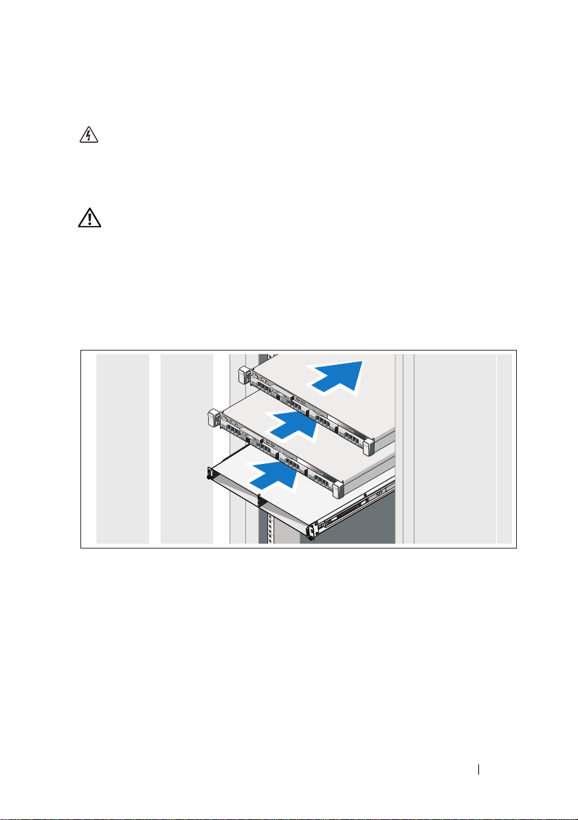
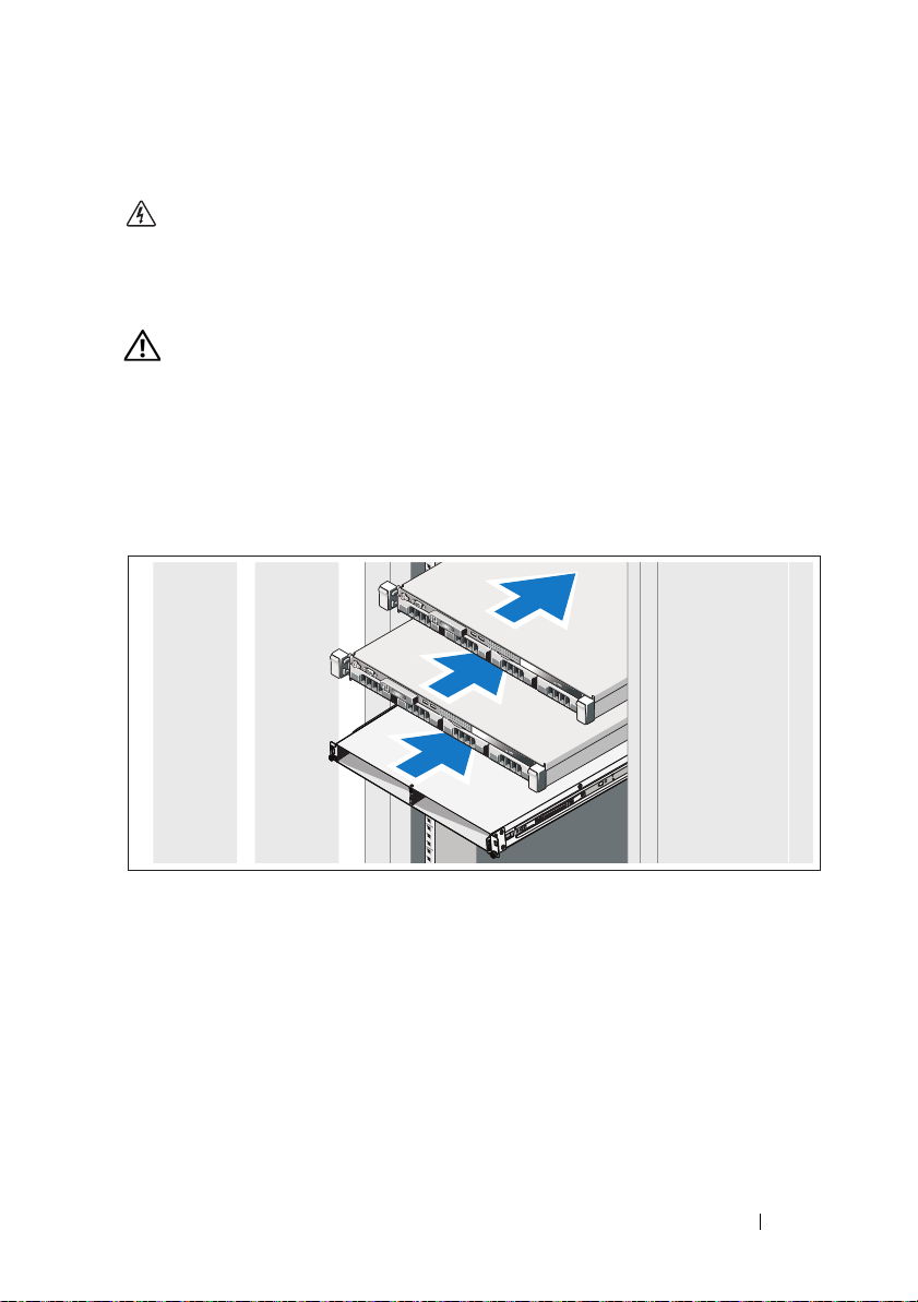
Installing the Rails, the System, and the Backup Power Supply in a Rack
Assemble the rails and install the system and backup power supply (BPS) in the
rack. Follow the safety instructions and the rack installation instructions
provided with the solution.
Getting Started With Your System
3
Page 6
Connecting the Battery in the BPS Power Module
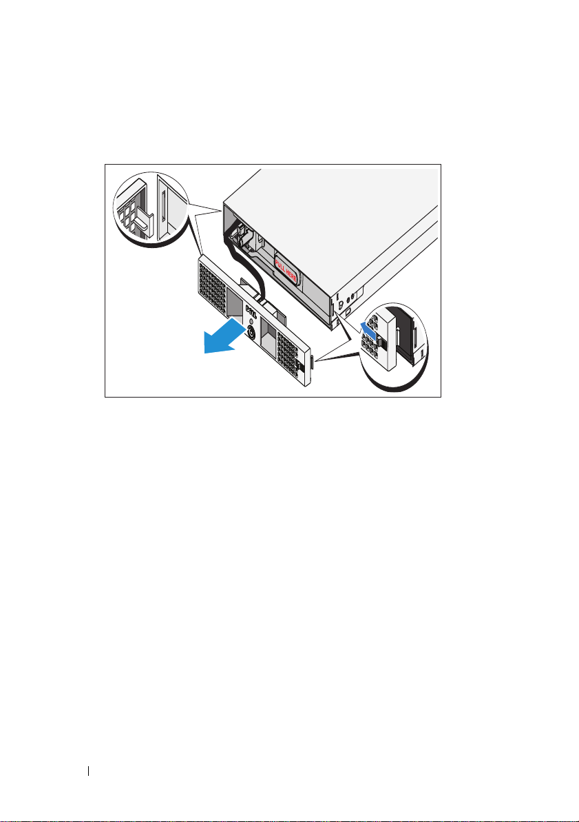
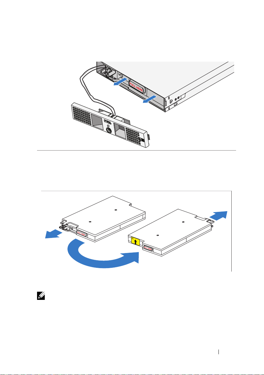
Removing the Power Module Front Cover
On the right side of the front cover, slide the latch to the left to retract the latch
hook. This hook secures the front cover to the right side of the chassis. Pull the
right side of the front cover from the chassis. Slide the front cover to the right to
disengage the hook. This hook secures the front cover to the left side of the chassis.
4
Getting Started With Your System
Page 7
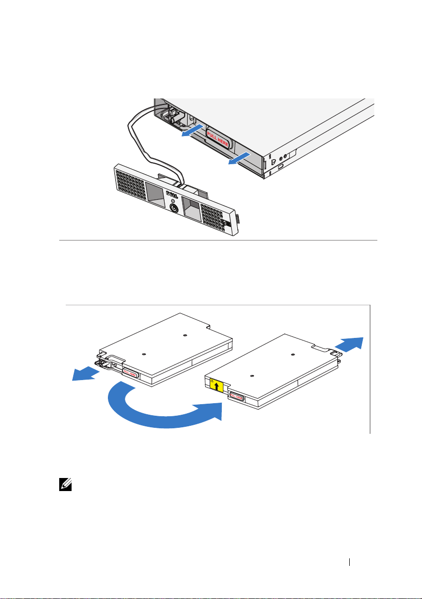
Removing the Battery
Pull the battery out of the power module.
Rotating the Battery
Rotate the battery 180° so the blind mate connector faces toward the back of
the power module chassis.
NOTE:
Ensure that the arrow on the yellow label is pointing up.
Getting Started With Your System
5
Page 8

Reinserting the Battery
Align the battery with the power module and reinsert the battery. Ensure that
the battery is fully seated in the power module. If the battery is not fully
inserted into the power module, the battery front cover will not close properly.
NOTE:
Always connect the battery pack before connecting the power cable.
NOTE:
You will not observe the blind mate connectors as they plug into the
receptacle in the back of the power module, but a small amount of arcing may
occur when connecting the battery pack. This is normal and does not damage the
unit or present any safety concern.
6
Getting Started With Your System
Page 9
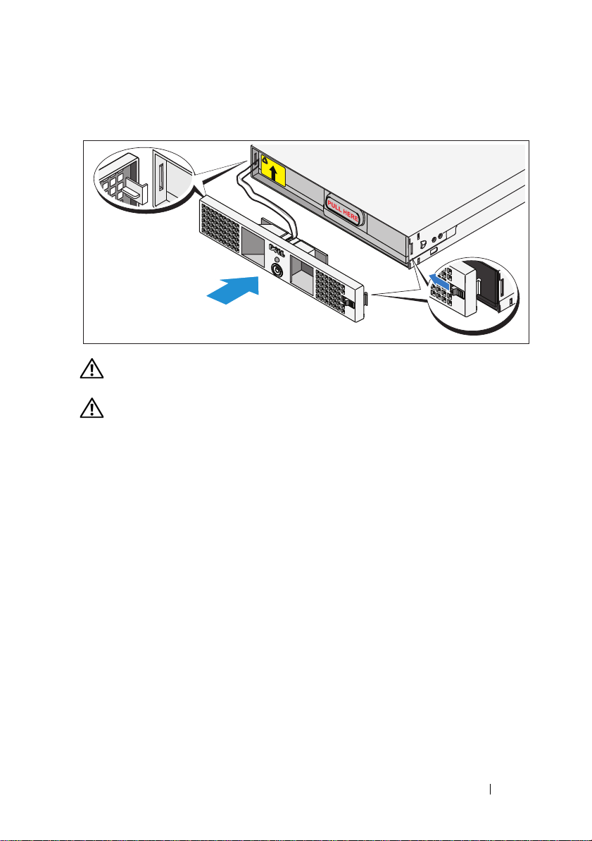
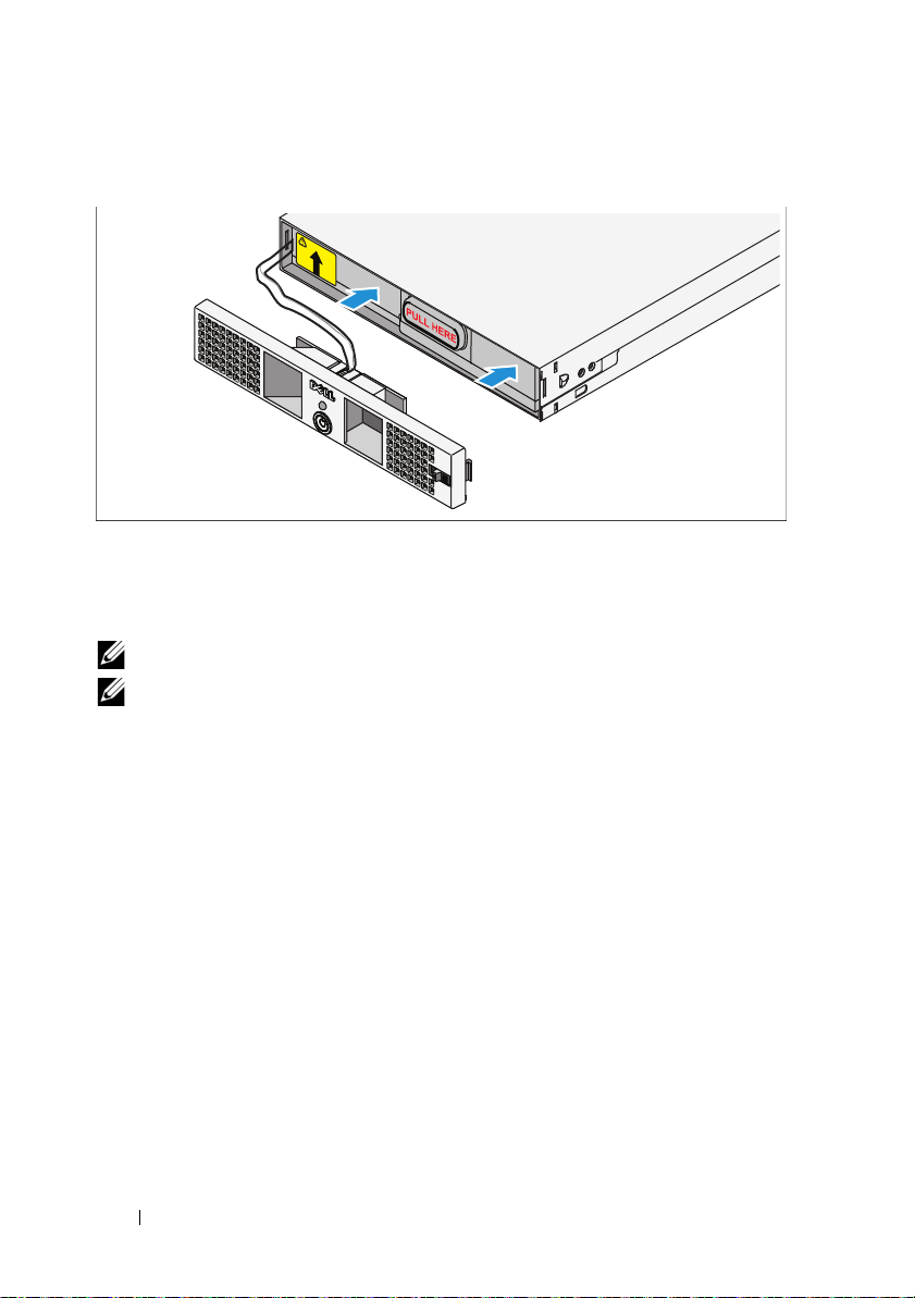
Securing the Power Module Front Cover
WARNING:
battery pack is inserted and connected.
WARNING:
module. For safety, do not allow the power module front cover to come in contact
with the battery pack.
For safety, always attach the power module front cover as soon as the
Align the front cover carefully before securing it to the power
On the left side of the first front cover, insert the hook into the open slot on the
left side of the chassis. On the right side of the front cover, slide the latch to the
left to retract the latch hook. Push the right side of the front cover forward to
the chassis. Release the latch to set the hook into the open slot on the right side
of the chassis.
Getting Started With Your System
7
Page 10

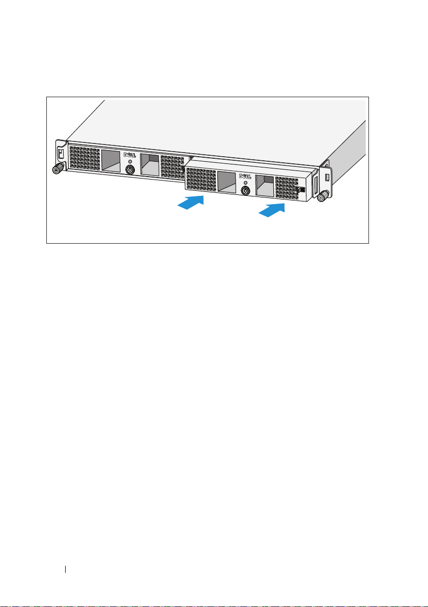
Inserting the Power Modules
Insert the power modules into the chassis module bay with the back panels
toward the back of the chassis.
8
Getting Started With Your System
Page 11
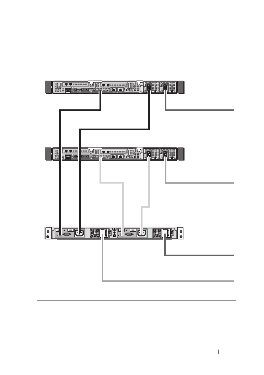
Cabling the Solution
PowerVault NX3500 system
PowerVault NX3500 system
Backup power supply
To power source 1
To power source 2
To power source 1
To power source 2
Cable the solution as shown in the illustration.
Getting Started With Your System
9
Page 12
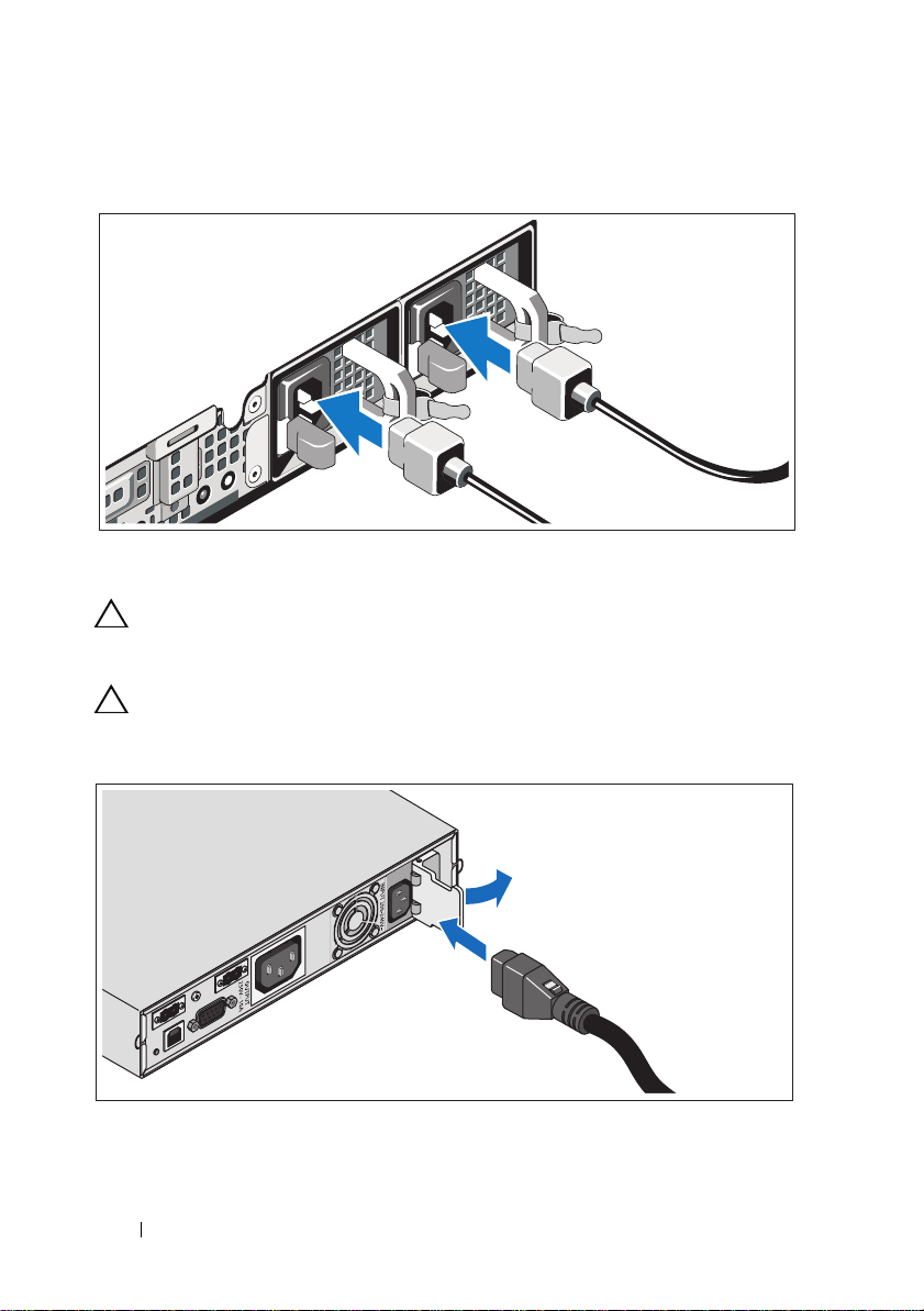
Connecting the Power Cable(s)
Connect the system’s power cable(s) to the system.
CAUTION:
C-13 output receptacles. Only use a power cord rated for the input power source
rating labeled next to the input connector on the power module back panel.
CAUTION:
Vac into a 120 V BPS will damage the BPS.
Both the 120 V (LV) and the 230 V (HV) power modules provide IEC 320
You must always verify the voltage rating of the BPS. Connecting a 230
Open the spring-loaded interlock cover for the input connector and connect the
power cable to the BPS.
10
Getting Started With Your System
Page 13
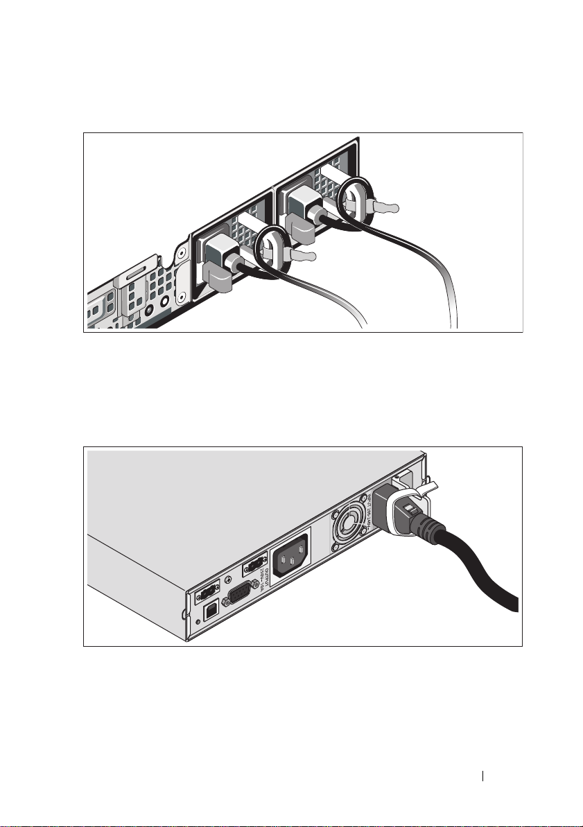
Securing the Power Cable(s)
Bend the system power cable(s) into a loop as shown in the illustration and
secure the cables to the brackets using the provided strap. Plug the other end of
one power cable to a grounded electrical outlet and the other cable to the BPS.
For more information, see "Cabling the Solution" on page 9.
Secure the power cable connected to the BPS as shown in the illustration.
Getting Started With Your System
11
Page 14
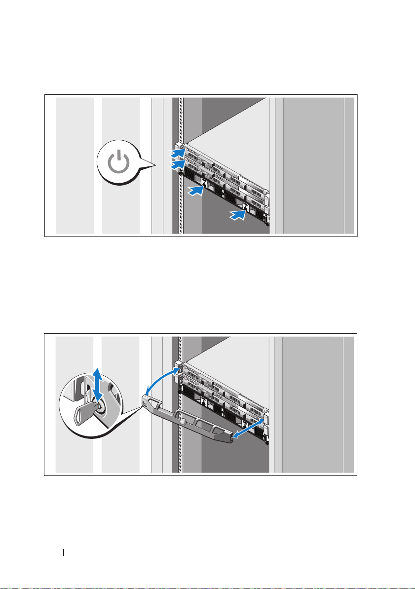
Turning On the Solution
Turn on the components in the following order:
1
The BPS
2
The PowerVault NX3500 systems
Installing the Optional Bezel
Install the bezel for the system (optional).
12
Getting Started With Your System
Page 15
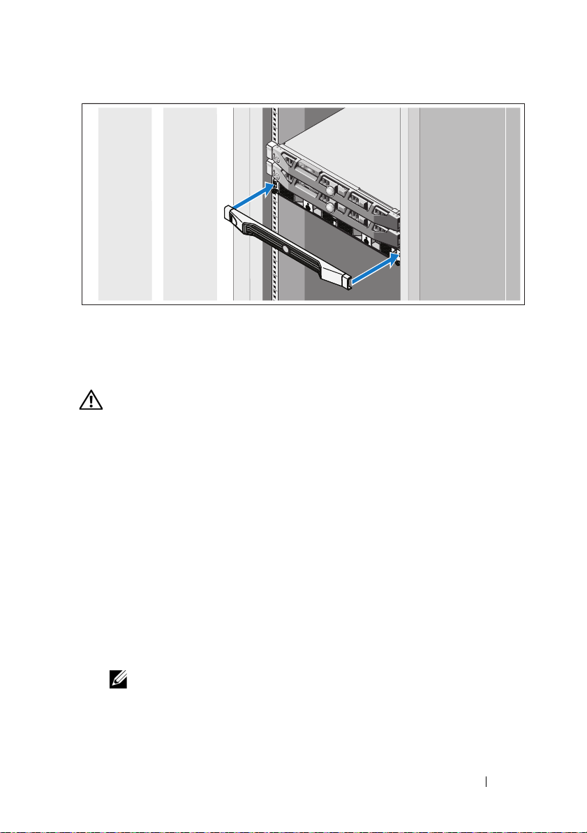
Install the bezel for the BPS (optional).
Other Information You May Need
WARNING:
your system. Warranty information may be included within this document or
as a separate document.
• The rack documentation included with your rack solution describes how to
install your system into a rack.
• The cable management arm instructions included with your rack solution
describes how to install the cable management arm into a rack.
• The
features and describes how to troubleshoot the system and install or
replace system components. This document is available online at
support.dell.com/manuals
• Any media that ships with your system that provides documentation and
tools for configuring and managing your system, including those
pertaining to the operating system, system management software, system
updates, and system components that you purchased with your system.
See the safety and regulatory information that shipped with
Hardware Owner’s Manual
provides information about system
.
NOTE:
Always check for updates on support.dell.com/manuals and read the
updates first because they often supersede information in other documents.
Getting Started With Your System
13
Page 16
Obtaining Technical Assistance
If you do not understand a procedure in this guide or if the system does not
perform as expected, see your
comprehensive hardware training and certification. See
more information. This service may not be offered in all locations.
Hardware Owner’s Manual
. Dell offers
dell.com/training
for
NOM Information (Mexico Only)
The following information is provided on the device described in this document
in compliance with the requirements of the official Mexican standards (NOM):
Importer:
Model Number Supply Voltage Frequency Current Consumption
E07S 100–240 V CA 50/60 Hz 5.2–2.6 A
DELL500WLV 100–140 V CA 50/60 Hz 15 A
DELL500WHV 200–250 V CA 50/60 Hz 10 A
Technical Specifications
PowerVault NX3500 System Specifications
Processor
Processor type Intel Xeon processor 3400 series
Expansion Bus
Bus type PCI Express Generation 2
Expansion slots One x16 half-length slot
One x8 half-length slot
NOTE:
Both the slots support x8 routing.
14
Getting Started With Your System
Page 17

Memory
Architecture 1333-MHz registered parity and non registered
DDR-III memory modules
Memory module sockets Six 240-pin
Memory module capacities 2 GB
Maximum RAM 12 GB
Drives
Hard drives Two 3.5" hot-swappable SATA drives
Optical drive One internal slimline SATA DVD-ROM
NOTE:
DVD devices are data only.
Connectors
Back
NIC
Serial
USB
Video
Front
Video
USB
Internal
USB
Two RJ-45 (for integrated 1-GB NICs)
9-pin, DTE, 16550-compatible
Two 4-pin, USB 2.0-compliant
15-pin VGA
15-pin VGA
Two 4-pin, USB 2.0-compliant
Two 4-pin, USB 2.0-compliant
Video
Video type Matrox G200, integrated in BMC
Video memory 8 MB graphics memory
Getting Started With Your System
15
Page 18

Power
AC power supply (per power supply)
Wa t ta g e
Vo lt ag e
Heat dissipation
Maximum inrush current
Batteries
System battery
Physical
Height 4.29 cm (1.69 in)
Width 43.4 cm (17.09 in)
Depth 61.26 cm (24.12 in)
Weight (maximum configuration) 15 kg (33.02 lbs)
Weight (empty configuration) 5.96 kg (13.12 lbs)
Environmental
NOTE:
For additional information about environmental measurements for specific
system configurations, see dell.com/environmental_datasheets.
Te mp e ra t u re
Operating
Storage
400 W
100–240 VAC, 50/60 Hz
1666 BTU/hr maximum
Under typical line conditions and over the entire
system ambient operating range, the inrush
current may reach 25 A per power supply for
10 ms or less.
CR 2032 3.0-V lithium coin cell
10 °C to 35 °C (50 °F to 95 °F) with a maximum
temperature gradation of 10 °C per hour
NOTE:
For altitudes above 2950 feet, the maximum
operating temperature is derated 1 ºF/550 ft.
–40 °C to 65 °C (–40 °F to 149 °F) with
a maximum temperature gradation of
20 °C per hour
16
Getting Started With Your System
Page 19

Environmental (continued)
Relative humidity
Operating
Storage
Maximum vibration
Operating
Storage
Maximum shock
Operating
Storage
Altitude
Operating
Storage
Airborne Contaminant Level
Class
8% to 85% (noncondensing) with a maximum
humidity gradation of 10% per hour
5% to 95% (noncondensing)
0.25 G at 3–200 Hz for 15 min
0.5 G at 3–200 Hz for 15 min
One shock pulse in the positive z axis (one pulse
on each side of the system) of 31 G for 2.6 ms
in the operational orientation
Six consecutively executed shock pulses in
the positive and negative x, y, and z axes
(one pulse on each side of the system) of 71 G
for up to 2 ms
–16 to 3048 m (–50 to 10,000 ft)
NOTE:
For altitudes above 2950 feet, the maximum
operating temperature is derated 1ºF/550 ft.
–16 to 10,600 m (–50 to 35,000 ft)
G1 as defined by ISA-S71.04-1985
Backup Power Supply Specifications
BPS Model List
120 V Model Dell BPS 500 W (LV)
230 V Model Dell BPS 500 W (HV)
Getting Started With Your System
17
Page 20

Physical (120 V and 230 V Models)
Dimensions (Width x Height x
Depth)
Rack Unit Size 1 U
Weight 30.0 kg (66.1 lb)
Electrical Input
Nominal Voltage
120 V Model
230 V Model
Nominal Voltage Range
120 V Model
230 V Model
Nominal Frequency
120 V and 230 V Models
Efficiency (Normal Mode)
120 V and 230 V Models
Noise Filtering
120 V and 230 V Models
Connections
120 V and 230 V Models
434 mm x 42 mm x 723 mm (1.4 in x 0.1 in x
2.4 in)
NOTE:
Bezel depth 33 mm (0.1 in) not included.
120 V
230 V
90–140 V
180–264 V
50/60 Hz auto-sensing, ±3 Hz
> 96%
Full-time EMI/RFI filtering
IEC 320-C14, 15 A for UL/CSA, otherwise 10 A
Electrical Output
Power Levels (Rated at Nominal Inputs)
120 V and 230 V Models
Regulation (Normal mode)
120 V Model
230 V Model
18
Getting Started With Your System
500 W
88–140 V
176–264 V
Page 21

Electrical Output (continued)
Regulation (Battery Mode), Nominal Voltage ±5%
120 V Model
230 V Model
Voltage Waveform
120 V and 230 V Models
Output Receptacles
120 V and 230 V Models
Environmental and Safety
Operating Temperature
120 V and 230 V Models
Transit/Storage Temperature
120 V and 230 V Models
Relative Humidity
120 V and 230 V Models
Operating Altitude
120 V and 230 V Models
Audible Noise
120 V and 230 V Models
Surge Suppression
120 V and 230 V Models
Safety Conformance
120 V Model
230 V Model
100–140 V
200–250 V
Sine wave
IEC 320-C13, 15 A for UL/CSA, otherwise 10 A
0 °C to 40 °C (32 °F to 104 °F)
Transit: -15 °C to 60 °C (5 °F to 140 °F)
Storage: -15 °C to 45 °C (5 °F to 113 °F)
0–95% noncondensing
Up to 3,048 m (0–10,000 ft) above sea level
Less than 50 dBA typical
ANSI/IEEE C62.41; 1991 Category B3
UL 1778 4th Edition; CSA C22.2, No. 107.3
UL 1778 4th Edition; CSA C22.2, No. 107.3;
IEC/EN 62040-1-1; IEC/EN 60950-1
Getting Started With Your System
19
Page 22

Environmental and Safety (continued)
Safety Markings
120 V Model
230 V Model
EMC (Class B)
120 V Model
230 V Model
Battery (120 V and 230 V Models)
Configuration 500 W: (4) 6 V, 9.0 Ah internal batteries
Battery Type 9.0 Ah
Voltage 500 W: 24 Vdc internal
Fuses BPS: (2) 40 A fuses
Type Sealed, maintenance-free, valve-regulated,
Charging Approximately 8 hours to 90% from a discharge of
Monitoring Advanced monitoring for earlier failure detection
UL, cUL, NOM, BSMI
GS, CE, GOST, NRCS, TISI, KC, CQC, BSMI,
UL, cUL, KVALITET, KONCAR, OTAN,
UKSERT, Uzbekistan GOST
FCC Part 15, CNS13438, KN22: 2005, VCCI
FCC Part 15, CNS13438, AS/NZS 62040.2,
KN22: 2005, GB7260.2, EN62040-2,
CISPR 22: 2006
lead-acid
50% rated load (usable capacity at nominal line
and no supplementary power supply load)
and warning
20
Getting Started With Your System
Page 23

Systémy
Dell PowerVault
NX3500
Začínáme se systémem
Regulační model: série E07S,
DELL500WLV a DELL500WHV
Page 24

Poznámky, upozornění a nebezpečí
POZNÁMKA:
počítače.
UPOZORNĚNÍ:
ztráty dat v případě nedodržení pokynů.
VAROVÁNÍ:
úrazu nebo smrti.
NEBEZPEČÍ:
nepředejdete, může vyústit ve vážné zranění nebo smrt.
POZNÁMKA označuje důležité informace, které pomáhají lepšímu využití
UPOZORNĚNÍ poukazuje na možnost poškození hardwaru nebo
VAROVÁNÍ upozorňuje na potenciální nebezpečí poškození majetku,
NEBEZPEČÍ označuje hrozící riziko. Pokud tomuto riziku
____________________
Informace v této publikaci se mohou bez předchozího upozornění změnit.
© 2011 Dell Inc.; Eaton Corporation. Všechna práva vyhrazena.
Jakákoliv reprodukce těchto materiálů bez písemného svolení společností Dell Inc. a Eaton
Corporation je přísně zakázána.
Ochranné známky použité v tomto textu: Dell™, logo DELL a PowerVault™ jsou ochranné známky
společnosti Dell Inc. Intel
v USA a dalších zemích.
V této publikaci mohou být použity další ochranné známky a obchodní názvy s odkazem na společnosti
vlastnící tyto známky a názvy nebo na jejich produkty. Společnost Dell Inc. nemá vlastnické zájmy
vůči ochranným známkám a obchodním názvům jiným než svým vlastním.
Regulační model: série E07S, DELL500WLV a DELL500WHV
Leden 2011 Č. dílu 9GJH6 Rev. A00
®
a Xeon® jsou registrované ochranné známky společnosti Intel Corporation
Page 25
Instalace a konfigurace
NEBEZPEČÍ:
vážné zranění nebo smrt, řid’te se následujícími pokyny. Záložní zdroj je pod
ŽIVOTU NEBEZPEČNÝM NAPĚTÍM. Veškeré opravy a servis by měli provádět
AUTORIZOVANÍ ZAMĚSTNANCI. Uvnitř záložního zdroje se NENACHÁZÍ ŽÁDNÉ
UŽIVATELEM OPRAVITELNÉ KOMPONENTY.
Chcete-li předejít nebezpečné situaci, která by mohla vyústit ve
VAROVÁNÍ:
pokyny dodané se systémem.
Před provedením následujícího postupu si prostudujte bezpečnostní
Rozbalení systému
Rozbalte systém a zkontrolujte jednotlivé komponenty.
Do stojanu namontujte kolejnice a systémový a záložní zdroj
Smontujte kolejnice a namontujte systémový a záložní zdroj (BPS) do stojanu.
Řid’te se bezpečnostními pokyny a pokyny pro montáž do stojanu, které byly
dodány společně se systémem.
Začínáme se systémem
23
Page 26

Jak do záložního zdroje zapojit baterii
Jak odstranit přední panel zdroje
Na pravé straně předního krytu zasuňte západku směrem vlevo. Tato západka
zajišt’uje přední kryt k pravé straně šasi. Vyjměte z šasi pravou stranu předního
krytu. Vysunutím předního krytu směrem doprava se západka uvolní. Tato západka
zajišt’uje přední kryt k levé straně šasi.
24
Začínáme se systémem
Page 27
Jak vyjmout baterii
Vyjměte baterii z modulu zdroje.
Jak otočit baterii
Otočte baterii o 180 °, aby byl konektor otočen směrem k zadní části šasi zdroje.
POZNÁMKA:
Ujistěte se, že šipka na žluté nálepce směřuje vzhůru.
Začínáme se systémem
25
Page 28
Jak zasadit baterii
Zarovnejte baterii do modulu zdroje a vložte ji dovnitř. Ujistěte se, že je baterie
plně zasazená v modulu zdroje. Pokud baterie není do modulu plně zasazena,
nebude možné zavřít přední kryt.
POZNÁMKA:
POZNÁMKA:
může ale dojít k mírnému zajiskření. Není to neobvyklé a neznačí to poškození jednotky
ani jiné nebezpečí.
Vždy nejdříve připojte baterii a teprve poté napájecí kabel.
Konektory baterie nebudou při připojování do zadní části šasi viditelné,
26
Začínáme se systémem
Page 29

Jak namontovat přední panel zdroje
VAROVÁNÍ:
vložení a zapojení baterie.
VAROVÁNÍ:
bezpečnostních důvodů nikdy nedovolte, aby přední panel modulu zdroje přišel do
kontaktu s baterií.
Z bezpečnostních důvodů vždy montujte přední kryt zdroje hned po
Před samotnou montáží přední kryt pečlivě zasad’te. Z
Na levé straně předního krytu vložte západku do otvoru na levé straně šasi. Na
pravé straně předního krytu zasuňte západku směrem vlevo. Zatlačte pravou
stranu předního krytu vpřed do šasi. Uvolněte západku, čímž dojde k jejímu
zasazení do otvoru na pravé straně šasi.
Začínáme se systémem
27
Page 30
Jak vložit modul zdroje
Modul zdroje vložte na příslušnou pozici. Zadní panely musí směřovat do zadní
části šasi.
28
Začínáme se systémem
Page 31

Kabeláž
Systém PowerVault NX3500
Systém PowerVault NX3500
Záložní zdroj
Ke zdroji 1
Ke zdroji 2
Ke zdroji 1
Ke zdroji 2
Kabely ved’te dle obrázku.
Začínáme se systémem
29
Page 32

Připojení napájecích kabelů
Připojte napájecí kabel(y) k systému.
UPOZORNĚNÍ:
Používejte pouze kabely vhodné pro vstupní napájení vyznačené vedle vstupního
konektoru na zadním panelu modulu.
UPOZORNĚNÍ:
zapojení 230 V stř. do 120 V dojde k poškození záložního zdroje.
Zdroje na 120 V (LV) i 230 V (HV) obsahují zásuvky IEC 320 C-13.
Vždy je nutno zkontrolovat jmenovité napětí záložního zdroje. Při
Otevřete kryt konektoru a připojte napájecí kabel k záložnímu zdroji.
30
Začínáme se systémem
Page 33

Zajištění napájecích kabelů
Ohněte napájecí kabely systému do smyčky, jak je znázorněno na obrázku, a
připevněte je dodanou páskou k držákům. Opačný konec napájecího kabelu
zapojte do uzemněné elektrické zásuvky a druhý kabel k záložnímu zdroji. Další
informace najdete v části „Kabeláž“ na straně 29.
Zajistěte napájecí kabel připojený k záložnímu zdroji, jak je vidět na obrázku.
Začínáme se systémem
31
Page 34

Jak zapnout systém
Zapněte komponenty v následujícím pořadí:
1
Záložní zdroj
2
Systémy PowerVault NX3500
Montáž volitelného rámu
Namontujte rám systému (volitelné).
32
Začínáme se systémem
Page 35

Namontujte rám záložního zdroje (volitelné).
Další užitečné informace
VAROVÁNÍ:
dodány se systémem. Informace o záruce jsou součástí tohoto dokumentu nebo
jsou přiloženy samostatně.
• Pokyny k instalaci do stojanu dodané se stojanovým řešením popisují
instalaci systému do stojanu.
• V dokumentaci týkající se správy kabelů, která byla dodána společně se
systémem, naleznete pokyny k montáži ramene pro správu kabelů.
•
Příručka majitele hardwaru
popisuje řešení problémů se systémem a instalaci nebo výměnu
komponent. Tento dokument je k dispozici online na adrese
support.dell.com/manuals
• Média dodaná se systémem obsahují dokumentaci a nástroje pro
konfiguraci a správu systému. Mohou být dodána například média týkající
se operačního systému, softwaru pro správu systému, aktualizací systému a
komponent zakoupených se systémem.
Prostudujte si informace o bezpečnosti a předpisech, které byly
obsahuje informace o funkcích systému a
.
POZNÁMKA:
uvedené na adrese
informace často nahrazují informace v ostatních dokumentech.
Vždy nejprve zkontrolujte a pročtěte aktualizované informace
support.dell.com/manuals
, protože tyto aktualizované
Začínáme se systémem
33
Page 36

Odborná pomoc
Nerozumíte-li některému z postupů popsaných v této příručce nebo nepracuje-li
systém podle očekávání, nahlédněte do
Dell nabízí v souvislosti s hardwarem kompletní školení a certifikaci. Další
informace naleznete na webových stránkách
nemusí být nabízena ve všech regionech.
Příručky majitele hardwaru
dell.com/training
. Společnost
. Tato služba
Informace NOM (jen pro Mexiko)
K zařízení popsanému v tomto dokumentu se vztahují v souladu s požadavky
oficiálních mexických norem NOM následující informace:
Dovozce:
Číslo modelu Napájecí napětí Frekvence Spotřeba proudu
E07S 100 – 240 V stř. 50/60 Hz 5,2 – 2,6 A
DELL500WLV 100 – 140 V stř. 50/60 Hz 15 A
DELL500WHV 200 – 250 V stř. 50/60 Hz 10 A
Technické údaje
Technické údaje systému PowerVault NX3500
Procesor
Typ procesoru Procesor řady Intel Xeon 3400
Rozšiřovací sběrnice
Typ sběrnice PCI Express 2. generace
Rozšiřovací sloty Jeden slot x16 poloviční délky
Jeden slot x8 poloviční délky
34
POZNÁMKA:
Začínáme se systémem
Oba sloty podporují směrování x8.
Page 37

Pamět’
Architektura 1333 MHz s registrovanou paritou a
neregistrované pamět’ové moduly DDR-III
Sloty pro pamět’ové moduly Šest 240 kolíkových
Kapacity pamět’ových modulů 2 GB
Maximum paměti RAM 12 GB
Jednotky
Pevné disky Dva 3,5 palcové pevné disky SATA vyměnitelné
za chodu
Optická jednotka Jeden interní disk SATA DVD-ROM (tenké
provedení)
Konektory
Vzadu
Sít’ové
Sériový
USB
Video
Vpředu
Video
USB
Interní
USB
POZNÁMKA:
pro data.
Dva konektory RJ-45 (pro integrované sít’ové
karty 1 Gb/s)
9 kolíkový, DTE, kompatibilní s normou 16550
Dva 4 kolíkové, USB 2.0
15 kolíkový VGA
15 kolíkový VGA
Dva 4 kolíkové, USB 2.0
Dva 4 kolíkové, USB 2.0
Zařízení DVD jsou určena pouze
Video
Typ grafiky Karta Matrox G200, integrovaná v řadiči BMC
Grafická pamět’ 8 MB grafické paměti
Začínáme se systémem
35
Page 38

Napájení
Střídavý proud (na jeden napájecí zdroj)
Výkon
Napětí
Odvod tepla
Maximální nárazový proud
Baterie
Systémová baterie
Rozměry
Výška 4,29 cm
Šířka 43,4 cm
Hloubka 61,26 cm
Hmotnost (maximální konfigurace) 15 kg
Hmotnost (prázdná konfigurace) 5,96 kg
Prostředí
POZNÁMKA:
systémové konfigurace na adrese
Te pl o ta
Provozní
Další informace o měřených údajích prostředí najdete pro jednotlivé
400 W
100 – 240 V (stř.), 50/60 Hz
Max. 1666 BTU/hod
V typických podmínkách napájení a v celém
provozním rozsahu systému může nárazový
proud dosáhnout 25 A na jeden napájecí zdroj
po dobu 10 ms nebo méně.
Lithium-iontová knoflíková baterie CR 2032
3,0 V
dell.com/environmental_datasheets
10 až 35 °C s maximálním nárůstem teploty o
10 °C za hodinu
POZNÁMKA:
900 metrů je maximální provozní teplota snížena o
1 °C na každých 168 metrů.
Skladovací
–40 až 65 °C s maximálním nárůstem teploty o
20 °C za hodinu
.
V nadmořských výškách nad
36
Začínáme se systémem
Page 39

Prostředí (pokračování)
Relativní vlhkost
Provozní
Skladovací
Maximální vibrace
Provozní
Skladovací
Maximální ráz
Provozní
Skladovací
Nadmořská výška
Provozní
Skladovací
Úroveň znečištění vzduchu
Třída
8 až 85 % (bez kondenzace) s maximálním
nárůstem vlhkosti o 10 % za hodinu
5 až 95 % (bez kondenzace)
0,25 G při 3–200 Hz po dobu 15 minut
0,5 G při 3–200 Hz po dobu 15 minut
Jeden rázový impuls v kladné ose z (jeden
impuls na každé straně systému) o síle 31 G
v délce do 2,6 ms v provozní orientaci
Šest po sobě jdoucích rázových impulsů v kladné
i záporné ose x, y a z (jeden impuls na každé
straně systému) o síle 71 G v délce do 2 ms
–16 až 3 048 m
POZNÁMKA:
900 metrů je maximální provozní teplota snížena o
1 °C na každých 167 metrů.
–16 až 10 600 m
G1 dle normy ISA-S71.04-1985
V nadmořských výškách nad
Technické údaje záložního zdroje
Seznam modelů záložního zdroje
Model 120 V Dell BPS 500 W (LV)
Model 230 V Dell BPS 500 W (HV)
Začínáme se systémem
37
Page 40

Fyzické (modely 120 V a 230 V)
Rozměry (Šířka x Výška x
Hloubka)
Velikost jednotky stojanu 1 U
Hmotnost 30,0 kg
Elektrický vstup
Jmenovité napětí
Model 120 V
Model 230 V
Rozsah jmenovitého napětí
Model 120 V
Model 230 V
Jmenovitá frekvence
Modely 120 V a 230 V
Výkon (Normální režim)
Modely 120 V a 230 V
Filtrování šumu
Modely 120 V a 230 V
Připojení
Modely 120 V a 230 V
434 mm x 42 mm x 723 mm
POZNÁMKA:
120 V
230 V
90 – 140 V
180 – 264 V
50/60 Hz automatické rozpoznání, ±3 Hz
> 96%
Neustálé filtrování EMI/RFI
IEC 320-C14, 15 A pro UL/CSA, jinak 10 A
Rám o hloubce 33 mm není započítán.
Elektrický výstup
Úrovně výkonu (při jmenovitých vstupech)
Modely 120 V a 230 V
Regulace (normální režim)
Model 120 V
Model 230 V
38
Začínáme se systémem
500 W
88 – 140 V
176 – 264 V
Page 41

Elektrický výstup (pokračování)
Regulace (Režim s baterií), jmenovité napětí ±5 %
Model 120 V
Model 230 V
Napět’ová křivka
Modely 120 V a 230 V
Zásuvky
Modely 120 V a 230 V
Životní prostředí a bezpečnost
Provozní teplota
Modely 120 V a 230 V
Přepravní/Skladovací teplota
Modely 120 V a 230 V
Relativní vlhkost
Modely 120 V a 230 V
Provozní nadmořská výška
Modely 120 V a 230 V
Slyšitelný hluk
Modely 120 V a 230 V
Ochrana proti přepětí
Modely 120 V a 230 V
Shoda s bezpečnostními předpisy
Model 120 V
Model 230 V
100 – 140 V
200 – 250 V
Sinusoida
IEC 320-C13, 15 A pro UL/CSA, jinak 10 A
0 až 40 °C
Přepravní: –15 °C až 60 °C
Skladovací: –15 °C až 45 °C
0 – 95% bez kondenzace
Až 3 048 m nad mořem
Obvykle méně než 50 dBA
ANSI/IEEE C62.41; 1991 Kategorie B3
UL 1778 4. edice; CSA C22.2, č. 107.3
UL 1778 4. edice; CSA C22.2, č. 107.3;
IEC/EN 62040-1-1; IEC/EN 60950-1
Začínáme se systémem
39
Page 42

Životní prostředí a bezpečnost (pokračování)
Bezpečnostní označení
Model 120 V
Model 230 V
EMC (třída B)
Model 120 V
Model 230 V
Baterie (modely 120 V a 230 V)
Konfigurace 500 W: vnitřní baterie (4) 6 V, 9,0 Ah
Typ baterie 9,0 Ah
Napětí 500 W: vnitřní 24 V stejn
Pojistky BPS: (2) 40 A pojistky
Typ Uzavřené, bezúdržbové VRLA
Nabíjení Přibližně na 90 % za 8 hodin ze stavu vybití pod
Monitoring Pokročilý monitoring pro včasnou detekci selhání
UL, cUL, NOM, BSMI
GS, CE, GOST, NRCS, TISI, KC, CQC, BSMI,
UL, cUL, KVALITET, KONCAR, OTAN,
UKSERT, GOST v Uzbekistánu
FCC část 15, CNS13438, KN22: 2005, VCCI
FCC část 15, CNS13438, AS/NZS 62040.2,
KN22: 2005, GB7260.2, EN62040-2,
CISPR 22: 2006
baterie (baterie řízené ventilem)
50 % jmenovitého zatížení (použitelná kapacita
při nominálním napětí a bez doplňkového zdroje)
a varování
40
Začínáme se systémem
Page 43

Systèmes Dell PowerVault
NX3500
Mise en route
Modèle réglementaire : séries E07S,
DELL500WLV et DELL500WHV
Page 44

Remarques, précautions, avertissements et
danger
REMARQUE :
vous aider à mieux utiliser votre ordinateur.
PRÉCAUTION :
matériel ou de perte de données en cas de non-respect des instructions données.
AVERTISSEMENT:
du matériel, de blessure corporelle ou de mort.
DANGER :
pas évité, résultera en une grave blessure ou la mort.
une REMARQUE indique des informations importantes qui peuvent
une PRÉCAUTION vous avertit d'un risque d'endommagement du
un AVERTISSEMENT indique un risque d'endommagement
une indication de DANGER indique un risque imminent qui, s'il n'est
____________________
Les informations que contient cette publication sont sujettes à modification sans préavis.
© 2011 Dell Inc. ; Eaton Corporation. Tous droits réservés.
La reproduction de ce document, de quelque manière que ce soit, sans l'autorisation écrite de Dell Inc.
est strictement interdite.
Marques utilisées dans ce document : Dell™, le logo DELL et PowerVault™ sont des marques de
Dell Inc., Intel
d'autres pays.
D'autres marques et noms commerciaux peuvent être utilisés dans ce document pour faire référence
aux entités se réclamant de ces marques et de ces noms ou à leurs produits. Dell Inc. rejette tout intérêt
propriétaire dans les marques et les noms commerciaux autres que les siens.
Modèle réglementaire : séries E07S, DELL500WLV et DELL500WHV
Janvier 2011 N/P 9GJH6 Rév. A00
®
et Xeon® sont des marques déposées d'Intel Corporation aux États-Unis et dans
Page 45

Installation et configuration
DANGER :
dangereuse qui, si elle n'est pas évitée, entraînera des blessures graves ou la mort :
le bloc d'alimentation de secours contient des TENSIONS LÉTALES. Seuls sont
habilités à le réparer et à le maintenir les MEMBRES DU PERSONNEL AGRÉÉS.
Le bloc d'alimentation de secours ne contient AUCUNE PIÈCE RÉPARABLE PAR
L'UTILISATEUR.
AVERTISSEMENT :
consignes de sécurité fournies avec le système.
Déballage de la solution
Déballez la solution et identifiez chaque élément.
Installation des rails, du système et du bloc d'alimentation de secours dans un rack
respectez les consignes suivantes afin d'éviter toute situation
avant d'exécuter la procédure ci-dessous, consultez les
Assemblez les rails et installez le système et le bloc d'alimentation de secours
(BPS) dans le rack. Respectez les consignes de sécurité et suivez les instructions
d'installation dans le rack fournies avec la solution.
Guide de mise en route
43
Page 46

Connexion de la batterie au module d'alimentation BPS
Retrait du cache avant du module d'alimentation
Sur le côté droit du cache avant, faites glisser le loquet vers la gauche afin d'en tirer
le crochet. Ce crochet fixe le cache avant au côté droit du châssis. Tirez le côté
droit du cache avant à l'écart du châssis. Faites glisser le cache avant vers la droite
afin de dégager le crochet. Ce crochet fixe le cache avant au côté gauche du châssis.
44
Guide de mise en route
Page 47

Retrait de la pile
Retirez la pile du module d'alimentation.
Rotation de la batterie
Faites pivoter la batterie de 180° afin que le connecteur permettant un
branchement en aveugle soit tourné vers l'arrière du châssis du module
d'alimentation.
REMARQUE :
assurez-vous que la flèche sur l'étiquette jaune pointe vers le haut.
Guide de mise en route
45
Page 48

Réinsertion de la batterie
Alignez la batterie avec le module d'alimentation et réinsérez-la. Assurez-vous
qu’elle est bien installée dans le module d'alimentation. Si elle n'est pas
complètement insérée, son cache avant ne se fermera pas correctement.
REMARQUE :
d'alimentation.
connectez toujours le bloc batterie avant de connecter le câble
REMARQUE :
visibles car ils se branchent dans le réceptacle à l'arrière du module d'alimentation,
mais vous pourrez observer une légère formation d'arc lors de la connexion du bloc
batterie. Ceci est normal et n'endommage en rien l'unité. Il n'y a aucune raison de
s'inquiéter.
46
Guide de mise en route
les connecteurs permettant un branchement en aveugle ne seront pas
Page 49

Fixation du cache avant du module d'alimentation
AVERTISSEMENT :
module d'alimentation dès que le bloc batterie est inséré et connecté.
pour des raisons de sécurité, attachez le cache avant du
AVERTISSEMENT :
module d'alimentation. Pour des raisons de sécurité, ne laissez pas le cache avant
du module d'alimentation entrer en contact avec le bloc batterie.
alignez soigneusement le cache avant avant de le fixer au
Sur le côté gauche du premier cache avant, insérez le crochet dans le logement
ouvert sur le côté gauche du châssis. Sur le côté droit du cache avant, faites
glisser le loquet vers la gauche afin d'en tirer le crochet. Poussez le côté droit du
cache avant vers l'avant du châssis. Dégagez le loquet pour placer le crochet
dans le logement ouvert sur le côté droit du châssis.
Guide de mise en route
47
Page 50

Insertion des modules d'alimentation
Insérez les modules d'alimentation dans la baie du module de châssis, les
panneaux arrière étant tournés vers l'arrière du châssis.
48
Guide de mise en route
Page 51

Câblage de la solution
Système PowerVault NX3500
Système PowerVault NX3500
Bloc d'alimentation de
secours
À la source d'alimentation 1
À la source d'alimentation 2
À la source d'alimentation 1
À la source d'alimentation 2
Câblez la solution de la façon illustrée.
Guide de mise en route
49
Page 52

Branchement du ou des câbles d'alimentation
Branchez le ou les câbles d'alimentation sur le système.
PRÉCAUTION :
réceptacles de sortie C-13 IEC 320. Utilisez uniquement un cordon
d'alimentation de valeur nominale appropriée pour la source d'alimentation d'entrée
proche du connecteur d'entrée situé sur le panneau arrière du module
d'alimentation.
PRÉCAUTION :
VCA 230 dans un BPS 120 V endommagera le BPS.
l
les modules d'alimentation 120 V (LV) et 230 V (HV) fournissent des
il faut toujours vérifier la tension nominale du BPS. Connecter un
Ouvrez le cache de verrouillage à ressort du connecteur d'entrée et connectez le
câble d'alimentation au BPS.
50
Guide de mise en route
Page 53

Fixation du ou des câbles d'alimentation
Faites une boucle avec chaque câble (voir l'illustration), puis fixez les câbles à
l'aide de l'armature prévue à cet effet. Branchez l'autre extrémité d'un câble
d'alimentation à une prise électrique mise à la masse et l'autre câble au BPS.
Pour plus d'informations, voir « Câblage de la solution » à la page 49.
Sécurisez le câble d'alimentation connecté au BPS de la façon illustrée.
Guide de mise en route
51
Page 54

Activation de la solution
Mettez les composants sous tension dans l'ordre suivant :
1
Le BPS
2
Les systèmes PowerVault NX3500
Installation du cadre en option
Installez le cadre du système (optionnel).
52
Guide de mise en route
Page 55

Installez le cadre du BPS (optionnel).
Autres informations utiles
AVERTISSEMENT :
réglementations qui accompagnent votre système. Les informations sur la garantie
se trouvent dans ce document ou dans un document distinct.
• La documentation fournie avec le rack indique comment installer le
système dans un rack.
• Les instructions concernant le bras de gestion des câbles incluses à la
solution de rack décrivent l'installation du bras de gestion des câbles
dans un rack.
•Le Manuel du propriétaire du matériel, qui présente les fonctionnalités
du système, contient des informations de dépannage ainsi que des
instructions d'installation ou de remplacement des composants du
système. Il est disponible en ligne sur support.dell.com/manuals.
• Tous les supports fournis avec le système contenant de la documentation
et des outils permettant de configurer et de gérer le système, y compris les
supports du système d'exploitation, du logiciel de gestion du système, des
mises à jour système et des composants système que vous avez achetés
avec le système.
REMARQUE :
support.dell.com/manuals et lisez-les informations de mise à jour en premier,
car elles remplacent souvent les informations que contiennent les autres
documents.
reportez-vous aux informations sur la sécurité et les
vérifiez toujours si des mises à jour sont disponibles sur le site
Guide de mise en route
53
Page 56

Assistance technique
Si vous ne comprenez pas une procédure décrite dans ce guide ou si le système
ne fonctionne pas comme prévu, voir le
Dell offre une formation complète avec certification sur le matériel. Consultez
dell.com/training
que dans certains pays.
pour de plus amples informations. Ce service n'est disponible
Manuel du propriétaire du matériel
.
Informations NOM (Mexique uniquement)
Les informations suivantes, concernant l'appareil décrit dans ce document,
sont fournies conformément aux exigences de la Norme Officielle Mexicaine
(NOM) :
Importateur :
Numéro de modèle Tension
d'alimentation :
E07S 100 à 240 V CA 50/60 Hz 5,2–2,6 A
DELL500WLV 100–140 V CA 50/60 Hz 15 A
DELL500WHV 200–250 V CA 50/60 Hz 10 A
Fréquence Consommation de
courant
Caractéristiques techniques
Caractéristiques du système PowerVault NX3500
Processeur
Type de processeur Processeur Intel Xeon Série 3400
Bus d'extension
Type de bus PCI Express 2ème génération
Logements d'extension Un logement x16 mi-longueur
Un logement x8 mi-longueur
54
REMARQUE :
charge le routage x8.
Guide de mise en route
les deux logements prennent en
Page 57

Mémoire
Architecture Barrettes de mémoire DDR-III à registres et avec
parité et sans registres, cadencées à 1333 MHz
Connecteurs de barrettes de
mémoire
Capacité des barrettes de mémoire 2 Go
RAM maximale 12 Go
Lecteurs
Disques durs Deux lecteurs SATA de 3,5 pouces remplaçables
Lecteur optique Un lecteur DVD-ROM SATA slimline
Connecteurs
Arrière
Carte réseau
Série
USB
Vidéo
Avant
Vidéo
USB
Interne
USB
Six de 240 broches
à chaud
REMARQUE :
uniquement pour l'enregistrement de données.
Deux connecteurs RJ-45
(pour cartes réseau intégrées de 1 Go)
Un connecteur DTE à 9 broches,
compatible 16550
Deux connecteurs à 4 broches,
compatibles USB 2.0
Un connecteur VGA à 15 broches
Un connecteur VGA à 15 broches
Deux connecteurs à 4 broches, compatibles
USB 2.0
Deux connecteurs à 4 broches, compatibles
USB 2.0
les périphériques DVD sont prévus
Vidéo
Type de vidéo Matrox G200, intégré au contrôleur BMC
Mémoire vidéo Mémoire graphique de 8 Mo
Guide de mise en route
55
Page 58

Alimentation
Alimentation secteur (par bloc d'alimentation)
Puissance
Te ns i on
Dissipation thermique
Appel de courant maximal
Piles
Pile du système
Caractéristiques physiques
Hauteur 4,29 cm (1,69 pouce)
Largeur 43,4 cm (17,09 pouces)
Profondeur 61,26 cm (24,12 pouces)
Poids (configuration maximale) 15 kg (33,02 livres)
Poids (configuration à vide) 5,96 kg (13,12 livres)
Environnement
REMARQUE :
configurations spécifiques, rendez-vous sur dell.com/environment_datasheets.
Te mp é ra t u re
En fonctionnement
Entreposage
pour en savoir plus sur les mesures d'exploitation liées à différentes
400 W
100- 240VCA, 50/60Hz
1666 BTU/h maximum
Dans des conditions de lignes typiques et dans
toute la gamme ambiante de fonctionnement
du système, le courant d'appel peut atteindre
25 A par bloc d'alimentation pendant une durée
maximale de 10 ms.
Pile bouton au lithium CR 2032 (3 V)
De 10 à 35 °C (de 50 à 95 °F) avec un gradient
thermique maximal de 10 °C par heure
REMARQUE :
2 950 pieds, la température maximale de
fonctionnement est réduite de 1 °F tous les
550 pieds.
De -40 à 65 °C (de -40 à 149 °F) avec un
gradient thermique maximal de 20 °C par heure
Pour les altitudes supérieures à
56
Guide de mise en route
Page 59

Environnement (suite)
Humidité relative
En fonctionnement
Entreposage
Tolérance maximale aux vibrations
En fonctionnement
Entreposage
Choc maximal
En fonctionnement
Entreposage
Altitude
En fonctionnement
Entreposage
Contaminants en suspension dans l'air
Classe
De 8 à 85 % (sans condensation) avec une
gradation d'humidité maximale de 10 % par
heure.
De 5 à 95 % (sans condensation)
0,25 G avec un balayage de 3 à 200 Hz pendant
15 minutes
0,5 G avec un balayage de 3 à 200 Hz pendant
15 minutes
Une impulsion de choc de 31 G de chaque côté
du système, pendant 2,6 ms sur l'axe z positif
(système installé dans la position de
fonctionnement)
Six chocs consécutifs de 71 G pendant un
maximum de 2 ms en positif et négatif sur les
axes x, y et z (une impulsion de chaque côté du
système)
De -16 à 3 048 m (de -50 à 10 000 pieds)
REMARQUE :
900 mètres (2 950 pieds), la température maximale
de fonctionnement est réduite de 0,55 °C (1 °F)
tous les 168 mètres (550 pieds).
De -16à 10600m (-50à 35000pieds)
G1 selon la norme ISA-S71.04-1985
Pour les altitudes supérieures à
Caractéristiques du bloc d'alimentation de secours
Liste des modèles de BPS
Modèle 120 V Dell BPS 500 W (LV)
Modèle 230 V Dell BPS 500 W (HV)
Guide de mise en route
57
Page 60

Caractéristiques physiques (Modèles 120 V et 230 V)
Dimensions (Largeur x Hauteur x
Profondeur)
Taille de l'unité de rack 1 U
Poids 30,0 kg (66,1 livres)
Consommation d'énergie
Tension nominale
Modèle 120 V
Modèle 230 V
Plage de tensions nominales
Modèle 120 V
Modèle 230 V
Fréquence nominale
Modèles 120 V et 230 V
Efficacité (Mode normal)
Modèles 120 V et 230 V
Filtrage du bruit
Modèles 120 V et 230 V
Connexions
Modèles 120 V et 230 V IEC 320-C14, 15 A pour UL/CSA, autrement 10 A
434 mm x 42 mm x 723 mm (1,4 po x 0,1 po x
2,4 po)
REMARQUE :
non comprise.
120 V
230 V
90–140 V
180–264 V
détection automatique 50/60 Hz, ±3 Hz
> 96%
Filtrage EMI/RFI de façon continue
profondeur du cadre 33 mm (0,1 po)
Sortie électrique
Niveaux de puissance (Entrées nominales)
Modèles 120 V et 230 V
Régulation (Mode normal)
Modèle 120 V
Modèle 230 V
58
Guide de mise en route
500 W
88–140 V
176–264 V
Page 61

Sortie électrique (suite)
Régulation (Mode Batterie), Tension nominale ±5%
Modèle 120 V
Modèle 230 V
Forme d'onde de tension
Modèles 120 V et 230 V
Réceptacles de sortie
Modèles 120 V et 230 V IEC 320-C14, 15 A pour UL/CSA, autrement 10 A
Environnement et sécurité
Température de fonctionnement
Modèles 120 V et 230 V
Température de
transport/entreposage
Modèles 120 V et 230 V
Humidité relative
Modèles 120 V et 230 V
Altitude de fonctionnement
Modèles 120 V et 230 V
Bruit audible
Modèles 120 V et 230 V
Élimination des surtensions
Modèles 120 V et 230 V
100–140 V
200–250 V
Onde sinusoïdale
de 0 °C à 40 °C (de 32 °F à 104 °F)
Transport : -15 °C to 60 °C (5 °F to 140 °F)
Transport : -15 °C to 45 °C (5 °F to 113 °F)
0–95% sans condensation
Jusqu'à 3 048 m (0–10 000 pieds) au-dessus du
niveau de la mer
Typiquement moins de 50 dBA
ANSI/IEEE C62.41 ; 1991 Catégorie B3
Guide de mise en route
59
Page 62

Environnement et sécurité (suite)
Respect de la sécurité
Modèle 120 V
Modèle 230 V
Marquage de sécurité
Modèle 120 V
Modèle 230 V
EMC (Classe B)
Modèle 120 V
Modèle 230 V
Batterie (Modèles 120 V et 230 V)
Configuration 500 W: (4) 6 V, batteries internes 9,0 Ah
Type de batterie 9,0 Ah
Tension 500 W : 24 Vcc interne
Fusibles BPS : (2) fusibles 40 A
Type Scellé, sans entretien, régulé par valve,
Charge en cours Approximativement 8 heures jusqu'à 90% à partir
Surveillance Surveillance avancée pour détection d'échec et
UL 1778 4e édition ; CSA C22.2, No. 3
UL 1778 4e édition ; CSA C22.2, No. 107.3 ;
IEC/EN 62040-1-1 ; IEC/EN 60950-1
UL, cUL, NOM, BSMI
GS, CE, GOST, NRCS, TISI, KC, CQC, BSMI,
UL, cUL, KVALITET, KONCAR, OTAN,
UKSERT, Uzbekistan GOST
FCC Alinéa 15, CNS13438, KN22: 2005, VCCI
FCC Alinéa 15, CNS13438, AS/NZS 62040.2,
KN22: 2005, GB7260.2, EN62040-2,
CISPR 22: 2006
au plomb
d'un déchargement de charge nominale de 50%
(capacité utilisable à ligne nominale et aucune
charge de bloc batterie supplémentaire)
avertissement accélérés
60
Guide de mise en route
Page 63

Dell PowerVault
NX3500-Systeme
Handbuch zum Einstieg
Vorschriftenmodell: E07S-Serie,
DELL500WLV und DELL500WHV
Page 64

Anmerkungen, Vorsichtshinweise, Warnungen
und Gefahr
ANMERKUNG:
sam, mit denen Sie den Computer besser einsetzen können.
VORSICHTSHINWEIS:
wiesen, die Hardwareschäden oder Datenverlust zur Folge haben können, wenn
die Anweisungen nicht befolgt werden.
WARNUNG:
sen, die materielle Schäden, Verletzungen oder sogar den Tod von Personen zur
Folge haben können.
GEFAHR:
hingewiesen, die, wenn sie nicht vermieden wird, den Tod oder schwerwiegende
Verletzungen zur Folge hat.
Eine ANMERKUNG macht auf wichtige Informationen aufmerk-
Hiermit werden Sie auf mögliche Gefahrenquellen hinge-
Durch eine WARNUNG werden Sie auf Gefahrenquellen hingewie-
Durch eine GEFAHR wird auf eine bevorstehende Gefahrensituation
____________________
Änderungen der Informationen in dieser Publikation sind vorbehalten.
© 2011 Dell Inc.; Eaton Corporation. Alle Rechte vorbehalten.
Die Vervielfältigung dieser Materialien in jeglicher Weise ohne vorherige schriftliche Genehmigung
von Dell Inc. und Eaton Corporation ist strengstens untersagt.
In diesem Text verwendete Marken: Dell™, das DELL Logo und PowerVault™ sind Marken von
Dell Inc. Intel
Ländern.
Andere in diesem Dokument möglicherweise verwendete Marken und Handelsbezeichnungen
beziehen sich auf die entsprechenden Eigentümer oder deren Produkte. Dell Inc. erhebt keinen
Anspruch auf Markenzeichen und Handelsbezeichnungen mit Ausnahme der eigenen.
Vorschriftenmodell: E07S-Serie, DELL500WLV und DELL500WHV
Januar 2011 Teilenr. 9GJH6 Rev. A00
®
und Xeon® sind eingetragene Marken der Intel Corporation in den USA und anderen
Page 65

Installation und Konfiguration
GEFAHR:
bevorstehenden Gefahrensituation helfen, die, wenn sie nicht vermieden wird,
den Tod oder eine schwere Verletzung zur Folge hat: Die Backup-Stromversorgung
enthält LEBENSGEFÄHRLICHE SPANNUNGEN. Alle Reparaturarbeiten und Service
dürfen NUR VON QUALIFIZIERTEN SERVICETECHNIKERN durchgeführt werden. Es
gibt KEINE DURCH DEN BENUTZER ZU WARTENDEN KOMPONENTEN innerhalb
der Backup-Stromversorgung.
Beachten Sie folgende Hinweise, die Ihnen bei der Vorbeugung einer
WARNUNG:
hinweise für das System.
Lesen Sie vor dem Ausführen der folgenden Schritte die Sicherheits-
Auspacken der Lösung
Entnehmen Sie die Lösung der Verpackung und identifizieren Sie die einzelnen
Komponenten.
Installation der Schienen, des Systems und der BackupStromversorgung in einem Rack
Montieren Sie die Schienen und installieren Sie das System und die BackupStromversorgung (BPS) im Rack. Befolgen Sie die Sicherheitshinweise und die
mit der Rack-Lösung gelieferten Rack-Installationsanleitung.
Handbuch zum Einstieg mit dem System
63
Page 66

Verbinden des Akkus im BPS-Stromversorgungsmodul
Entfernen der vorderen Stromversorgungsmodul-Abdeckung
Schieben Sie die Verriegelung auf der rechten Seite der vorderen Abdeckung nach
links, um den Verriegelungshaken zurückzuschieben. Der Haken befestigt die
Frontverkleidung an der rechten Seite des Gehäuses. Schieben Sie die rechte Seite
der vorderen Abdeckung vom Gehäuse weg. Schieben Sie die vordere Abdeckung
nach rechts, um den Haken zu lösen. Der Haken befestigt die Frontverkleidung an
der linken Seite des Gehäuses.
64
Handbuch zum Einstieg mit dem System
Page 67

Entfernen des Akkus
Ziehen Sie den Akku aus dem Stromversorgungsmodul heraus.
Umdrehen des Akkus
Drehen Sie den Akku um 180 Grad, sodass der Blind-Mate-Anschluss zur Rückseite des Stromversorgungsmodul-Gehäuses weist.
ANMERKUNG:
weist.
Stellen Sie sicher, dass der Pfeil auf dem Aufkleber nach oben
Handbuch zum Einstieg mit dem System
65
Page 68

Erneutes Einsetzen des Akkus
Richten Sie den Akku am Stromversorgungsmodul aus und setzen Sie den Akku
wieder ein. Stellen Sie sicher, dass der Akku fest im Stromversorgungsmodul
sitzt. Falls der Akku nicht vollständig im Stromversorgungsmodul sitzt, kann die
vordere Akku-Abdeckung nicht ordnungsgemäß geschlossen werden.
ANMERKUNG:
Stromkabel anschließen.
ANMERKUNG:
der Buchse auf der Rückseite des Stromversorgungsmoduls angeschlossen werden, es kann aber zu einem Elektrodenüberschlag beim Verbinden des Akkupacks
kommen. Das ist normal und beschädigt nicht die Einheit und stellt kein Sicherheitsrisiko dar.
Schließen Sie immer zuerst den Akkupack an, bevor Sie das
Sie erkennen die Blind-Mate-Anschlüsse nicht, während sie an
66
Handbuch zum Einstieg mit dem System
Page 69

Anbringen der vorderen Stromversorgungsmodul-Abdeckung
WARNUNG:
gungsmodul-Abdeckung an, sobald der Akkupack eingesetzt und verbunden ist.
WARNUNG:
Stromversorgungsmodul befestigen. Achten Sie aus Sicherheitsgründen darauf,
dass die vordere Stromversorgungsmodul-Abdeckung nicht in Berührung mit dem
Akkupack kommt.
Sicherheitshalber bringen Sie immer die vordere Stromversor-
Richten Sie vorsichtig die Frontverkleidung aus, bevor Sie sie am
Setzen Sie den Haken auf der linken Seite der ersten Frontverkleidung in den
geöffneten Steckplatz auf der linken Seite des Gehäuses ein. Schieben Sie die
Verriegelung auf der rechten Seite der vorderen Abdeckung nach links, um den
Verriegelungshaken zurückzuschieben. Schieben Sie die rechte Seite der vorderen Abdeckung zum Gehäuse nach vorne. Entriegeln Sie die Verriegelungstaste, um den Haken in den geöffneten Steckplatz auf der rechten Seite des
Gehäuses einzustellen.
Handbuch zum Einstieg mit dem System
67
Page 70

Einsetzen der Stromversorgungsmodule
Setzen Sie die Stromversorgungsmodule in den Gehäusemodulschacht so ein,
dass die Rückseite der Module zur Gehäuserückseite weist.
68
Handbuch zum Einstieg mit dem System
Page 71

Verkabelung der Lösung
PowerVault NX3500-System
PowerVault NX3500-System
BackupStromversorgung
Zu Stromquelle 1
Zu Stromquelle 2
Zu Stromquelle 1
Zu Stromquelle 2
Verkabeln Sie die Lösung wie in der Abbildung dargestellt.
Handbuch zum Einstieg mit dem System
69
Page 72

Anschließen des/der Netzstromkabel(s)
Verbinden Sie das bzw. die Stromversorgungskabel mit dem System.
VORSICHTSHINWEIS:
(Hochspannung)-Stromversorgungsmodule stellen IEC 320 C-13-Ausgangsbuchsen
bereit. Verwenden Sie ausschließlich ein Netzkabel, das für die Betriebsspannung ausgelegt ist, die den Spezifikationen auf dem Aufkleber neben dem Eingangsanschluss auf der Rückseite des Stromversorgungsmoduls entspricht.
VORSICHTSHINWEIS:
Durch das Anschließen einer 230 V Wechselspannung an die 120 V BPS wird BPS
beschädigt.
Sowohl die 120 V (Niederspannung)- als auch die 230 V
Überprüfen Sie immer die Betriebsspannung der BPS.
70
Handbuch zum Einstieg mit dem System
Page 73

Öffnen Sie den federbelasteten Verriegelungsdeckel für den Eingangsanschluss
und schließen sie das Netzkabel an die BPS an.
Befestigen des/der Netzstromkabel(s)
Bilden Sie mit dem(n) System-Netzkabel(n) wie abgebildet eine Schlaufe, und
sichern Sie die Kabel mit dem beigefügten Riemen an den Klammern. Stecken
Sie das andere Ende des Netzkabels in eine geerdete Steckdose und das andere
Kabel in die BPS ein. Weitere Informationen finden Sie unter „Verkabelung der
Lösung“ auf Seite 69.
Handbuch zum Einstieg mit dem System
71
Page 74

Befestigen Sie das mit der BPS verbundene Netzkabel wie abgebildet.
Einschalten der Lösung
Schalten Sie die Komponenten in der folgenden Reihenfolge ein:
1
Die BPS
2
Die PowerVault NX3500-Systeme
72
Handbuch zum Einstieg mit dem System
Page 75

Anbringen der optionalen Frontblende
Installieren Sie die Verkleidung für das System (optional).
Installieren Sie die Verkleidung für die BPS (optional).
Handbuch zum Einstieg mit dem System
73
Page 76

Weitere nützliche Informationen
WARNUNG:
dem Computer geliefert wurden. Garantiebestimmungen können möglicherweise
als separates Dokument beigelegt sein.
• In der zusammen mit der Rack-Lösung gelieferten Rack-Dokumentation
ist beschrieben, wie das System in einem Rack installiert wird.
• In der zusammen mit der Rack-Lösung gelieferten Hinweisen zum Kabelführungsarm ist beschrieben, wie der Kabelführungsarm in einem Rack
installiert wird.
•Im
• Alle im Lieferumfang Ihres Systems enthaltenen Medien mit Dokumen-
Hardware-Benutzerhandbuch
funktionen, Fehlerbehebung im System und zum Installieren oder Austauschen von Systemkomponenten. Sie finden dieses Dokument online
unter
tationen und Hilfsmitteln zur Konfiguration und Verwaltung Ihres Systems, insbesondere in Bezug auf Betriebssystem, Systemverwaltungssoftware, System-Updates und mit dem System erworbene Komponenten.
ANMERKUNG:
aktualisierte Dokumente vorliegen, lesen Sie diese immer zuerst, denn frühere
Informationen werden damit gegebenenfalls ungültig.
Beachten Sie die Sicherheits- und Betriebsbestimmungen, die mit
finden Sie Informationen über System-
support.dell.com/manuals
Wenn auf der Website support.dell.com/manuals
.
Anfordern von technischer Unterstützung
Falls Sie einen Vorgang in diesem Handbuch nicht nachvollziehen können oder
das System sich nicht wie erwartet verhält, nehmen Sie das
handbuch
zierungen an. Nähere Informationen erhalten Sie unter
Dienstleistungen stehen unter Umständen nicht an allen Standorten zur Verfügung.
74
zur Hand. Dell bietet umfangreiche Hardware-Schulungen und Zertifi-
Handbuch zum Einstieg mit dem System
Hardware-Benutzer-
dell.com/training.
Diese
Page 77

NOM-Informationen (nur Mexiko)
Die folgenden Informationen beziehen sich auf das in diesem Dokument
beschriebene Gerät und entsprechen den mexikanischen Normen (NOM):
Importeur:
Modellnummer Netzspannung Frequenz Stromverbrauch
E07S 100-240 V Wechselspannung 50/60 Hz 5,2-2,6 A
DELL500WLV 100–140 V Wechselspannung 50/60 Hz 15 A
DELL500WHV 200–250 V Wechselspannung 50/60 Hz 10 A
Technische Daten
Technische Daten des PowerVault NX3500-Systems
Prozessor
Prozessortyp Reihe Intel Xeon-Prozessor 3400
Erweiterungsbus
Bustyp PCI-Express (2. Generation)
Erweiterungssteckplätze Ein x16-Steckplatz, halbe Baulänge
Ein x8-Steckplatz, halbe Baulänge
ANMERKUNG:
x8-Routing.
Beide Steckplätze unterstützen
Speicher
Architektur 1333-MHz registrierte Parität und nicht-
registrierte DDR-III-Speichermodule
Speichermodulsockel 6 x 240-polig
Kapazität der Speichermodule 2 GB
RAM (höchstens) 12 GB
Handbuch zum Einstieg mit dem System
75
Page 78

Laufwerke
Festplattenlaufwerke Zwei 3,5-Zoll hot-swap-fähige SATA-Laufwerke
Optisches Laufwerk Ein internes SATA-DVD-ROM (Slimline)
ANMERKUNG:
DVD-Geräte sind reine Daten-
laufwerke.
Anschlüsse
Rückseite
NIC
Seriell
USB
Grafikkarte
Zwei RJ-45 (für integrierte 1-GB-NICs)
9-polig, DTE, 16550-kompatibel
Zwei 4-polige Anschlüsse, USB-2.0-konform
VGA, 15-polig
Vorderseite
Grafikkarte
USB
VGA, 15-polig
Zwei 4-polige Anschlüsse, USB-2.0-konform
Intern
USB
Zwei 4-polige Anschlüsse, USB-2.0-konform
Grafikkarte
Grafikkartentyp Matrox G200, integriert im BMC
Grafikspeicher 8 MB Grafikspeicher
76
Handbuch zum Einstieg mit dem System
Page 79

Leistung
Netzstromversorgung (je Netzteil)
Leistung
Spannung
Wärmeabgabe
Maximaler Einschaltstrom
Batterien
Systembatterie
Abmessungen
Höhe 4,29 cm
Breite 43,4 cm
Tiefe 61,26 cm
Gewicht (maximale Konfiguration) 15 kg
Gewicht (leere Konfiguration) 5,96 kg
Umgebungsbedingungen
ANMERKUNG:
Systemkonfigurationen finden Sie unter dell.com/environmental_datasheets.
Temperatur
Betrieb
Lagerung
Weitere Informationen zu Umgebungsbedingungen bei verschiedenen
400 W
100-240 VAC, 50/60 Hz
Maximal 1666 BTU/h
Unter typischen Leitungsbedingungen und über
den gesamten Umgebungsbetriebsbereich des
Systems kann der Einschaltstrom pro Netzteil
(über einen Zeitraum von 10 ms oder weniger)
25 A erreichen.
Lithium-Knopfzelle CR 2032 (3,0 V)
10 °C bis 35 °C mit einem maximalen
Temperaturanstieg von 10 °C pro Stunde
ANMERKUNG:
verringert sich die maximale Betriebstemperatur
um 1 ºC/300 m.
-40 °C bis 65 °C bei einem maximalen
Temperaturverlauf von 20 °C pro Stunde
Bei Höhen über 900 Meter
Handbuch zum Einstieg mit dem System
77
Page 80

Umgebungsbedingungen (fortgesetzt)
Relative Luftfeuchtigkeit
Betrieb
Lagerung
Zulässige Erschütterung
Betrieb
Lagerung
Zulässige Stoßeinwirkung
Betrieb
Lagerung
Höhe über NN
Betrieb
Lagerung
Luftverschmutzungsklasse
Klasse
8% bis 85% (nicht-kondensierend) mit einem
Luftfeuchtigkeitsgradienten von 10 % pro
Stunde
5 bis 95% (nicht kondensierend)
0,25 G bei 3-200 Hz, 15 Min. lang
0,5 G bei 3-200 Hz, 15 Min. lang
Ein Stoß von 31 G in der positiven z-Achse (ein
Stoß auf jeder Seite des Systems) über einen
Zeitraum von 2,6 ms in der Betriebsrichtung
Sechs nacheinander ausgeführte Stöße mit 71 G
von bis zu 2 ms Dauer in positiver und negativer
X-, Y- und Z-Richtung (ein Stoß auf jeder Seite
des Systems)
-16 bis 3.048 m
ANMERKUNG:
verringert sich die maximale Betriebstemperatur
um 1 ºC/300 m.
-16 bis 10.600 m
G1 gemäß ISA-S71.04-1985
Bei Höhen über 900 Meter
78
Handbuch zum Einstieg mit dem System
Page 81

Technische Daten der Backup-Stromversorgung
BPS-Modellliste
120 V-Modell Dell BPS 500 W (Niederspannung)
230 V-Modell Dell BPS 500 W (Hochspannung)
Physikalisch (120 V- und 230 V-Modelle)
Dimensionen (Breite x Höhe x
Tiefe)
Rack-Einheitsgröße 1 U
Gewicht 30,0 kg
Elektrischer Eingang
Nennspannung
120 V-Modell
230 V-Modell
Nennspannungsbereich
120 V-Modell
230 V-Modell
Nennfrequenz
120 V- und 230 V-Modelle
Effizienz (Normalbetrieb)
120 V- und 230 V-Modelle
Geräuschfilterung
120 V- und 230 V-Modelle
Verbindungen
120 V- und 230 V-Modelle
434 mm x 42 mm x 723 mm
ANMERKUNG:
nicht im Lieferumfang enthalten.
120 V
230 V
90–140 V
180–264 V
50/60 Hz Autosensing, ±3 Hz
> 96 %
Permanente EMI/RFI-Filterung
IEC 320-C14, 15 A für UL/CSA, ansonsten 10 A
Tiefe der Frontverkleidung 33 mm
Elektrischer Ausgang
Stromstufen (Nenn-Eingangswerte)
120 V- und 230 V-Modelle
500 W
Handbuch zum Einstieg mit dem System
79
Page 82

Elektrischer Ausgang (fortgesetzt)
Regelung (Normalbetrieb)
120 V-Modell
230 V-Modell
Regelung (Akkumodus), Nennspannung ±5 %
120 V-Modell
230 V-Modell
Voltage-Waveform
120 V- und 230 V-Modelle
Ausgangsbuchsen
120 V- und 230 V-Modelle
Umweltschutz und Sicherheit
Betriebstemperatur
120 V- und 230 V-Modelle
Transit-/Lagerungstemperatur
120 V- und 230 V-Modelle
Relative Luftfeuchtigkeit
120 V- und 230 V-Modelle
Betriebshöhe
120 V- und 230 V-Modelle
Hörbares Geräusch
120 V- und 230 V-Modelle
Überspannungsschutz
120 V- und 230 V-Modelle
Sicherheitskonformität
120 V-Modell
230 V-Modell
88–140 V
176–264 V
100–140 V
200–250 V
Sinuswelle
IEC 320-C13, 15 A für UL/CSA, ansonsten 10 A
0° C bis 40 °C
Transit: -15 °C bis 60 °C
Lagerung: -15 °C bis 45 °C
0–95 % nicht kondensierend
Bis zu 3.048 m über dem Meeresspiegel
Weniger als 50 dBA typisch
ANSI/IEEE C62.41; 1991 Kategorie B3
UL 1778 4. Edition; CSA C22.2, Nr. 107.3
UL 1778 4. Edition; CSA C22.2, Nr. 107.3;
IEC/EN 62040-1-1; IEC/EN 60950-1
80
Handbuch zum Einstieg mit dem System
Page 83

Umweltschutz und Sicherheit (fortgesetzt)
Sicherheitsmarkierungen
120 V-Modell
230 V-Modell
EMC (Klasse B)
120 V-Modell
230 V-Modell
Akku (120 V- und 230 V-Modelle)
Konfiguration 500 W: (4) 6 V, 9,0 Ah interne Akkus
Akku-/Batterietyp: 9,0 Ah
Spannung 500 W: 24 V Gleichstrom intern
Sicherungen BPS: (2) 40 A Sicherungen
Typ Versiegelt, instandhaltungsfrei, ventilgeregelt,
Wird geladen Ungefähr 8 Stunden bei 90 % von einer
Überwachung Erweiterte Überwachung für Früherkennung von
UL, cUL, NOM, BSMI
GS, CE, GOST, NRCS, TISI, KC, CQC, BSMI,
UL, cUL, KVALITET, KONCAR, OTAN,
UKSERT, Uzbekistan GOST
FCC Part 15, CNS13438, KN22: 2005, VCCI
FCC Part 15, CNS13438, AS/NZS 62040.2,
KN22: 2005, GB7260.2, EN62040-2,
CISPR 22: 2006
Bleisäure
Entladung von 50 % Nennlast (nutzbare
Kapazität bei Nennspannung und keine
zusätzliche Stromversorgungslast)
Fehlern und Warnungen
Handbuch zum Einstieg mit dem System
81
Page 84

82
Handbuch zum Einstieg mit dem System
Page 85

Συστήματα
Dell PowerVault NX3500
Τα πρώτα βήματα με
το σύστημά σας
Μοντέλο κατά τους κανονισμούς: Σειρές E07S,
DELL500WLV και DELL500WHV
Page 86

Σημειώσεις, Προσοχή, Προειδοποιήσεις και
Κίνδυνοι
ΣΗΜΕΙΩΣΗ:
βοηθούν να χρησιμοποιείτε καλύτερα τον υπολογιστή σας.
ΠΡΟΣΟΧΗ:
δεδομένων, αν δεν ακολουθούνται οι οδηγίες.
ΠΡΟΕΙ∆ΟΠΟΙΗΣΗ:
ζημιά, σωματική βλάβη ή θάνατο.
ΚΙΝ∆ΥΝΟΣ:
οποία, εάν δεν αποφευχθεί, θα οδηγήσει σε θάνατο ή σοβαρή σωματική
βλάβη.
Η ΣΗΜΕΙΩΣΗ υποδεικνύει σημαντικές πληροφορίες που σας
Η ΠΡΟΣΟΧΗ υποδηλώνει δυνητική υλική ζημιά ή απώλεια
Η ΠΡΟΕΙ∆ΟΠΟΙΗΣΗ υποδηλώνει δυνητική υλική
Ο ΚΙΝ∆ΥΝΟΣ υποδηλώνει επικείμενη επικίνδυνη κατάσταση η
____________________
Οι πληροφορίες αυτής της δημοσίευσης υπόκεινται σε αλλαγές χωρίς ειδοποίηση.
© 2011 Dell Inc., Eaton Corporation. Με την επιφύλαξη παντός δικαιώματος.
Απαγορεύεται αυστηρά η αναπαραγωγή του υλικού με οποιονδήποτε τρόπο, αν δεν υπάρχει σχετική
γραπτή άδεια της Dell Inc. και της Eaton Corporation.
Εμπορικά σήματα που χρησιμοποιούνται στο παρόν κείμενο: η ονομασία Dell™, το λογότυπο DELL
και η ονομασία PowerVault™ είναι εμπορικά σήματα
είναι σήματα κατατεθέντα της Intel Corporation στις Η.Π.Α. και σε άλλες χώρες.
Άλλα εμπορικά σήματα και εμπορικές ονομασίες μπορεί να χρησιμοποιούνται στην παρούσα έκδοση
αναφερόμενα είτε στους κατόχους των σημάτων και των ονομάτων είτε στα προϊόντα τους. Η
Dell Inc. παραιτείται από κάθε δικαίωμα σε εμπορικά σήματα και εμπορικές ονομασίες τρίτων.
Μοντέλο κατά τους κανονισμούς: Σειρές E07S, DELL500WLV και DELL500WHV
Ιανουάριος 2011 P/N 9GJH6 Αναθ. A00
της Dell Inc. Οι ονομασίες Intel®και Xeon®
Page 87

Εγκατάσταση και ρύθμιση
ΚΙΝ∆ΥΝΟΣ:
επικείμενη επικίνδυνη κατάσταση η οποία, εάν δεν αποφευχθεί, θα οδηγήσει
σε θάνατο ή σοβαρή σωματική βλάβη: Η εφεδρική παροχή τροφοδοσίας
περιέχει ΘΑΝΑΤΗΦΟΡΕΣ ΤΑΣΕΙΣ. Όλες οι εργασίες επισκευής και
συντήρησης θα πρέπει να εκτελούνται από ΕΞΟΥΣΙΟ∆ΟΤΗΜΕΝΟ
ΠΡΟΣΩΠΙΚΟ ΣΕΡΒΙΣ ΜΟΝΟ. ∆εν υπάρχουν ΜΕΡΗ ΠΟΥ ΜΠΟΡΟΥΝ ΝΑ
ΕΠΙΣΚΕΥΑΣΤΟΥΝ ΑΠΟ ΤΟΝ ΧΡΗΣΤΗ στο εσωτερικό της εφεδρικής παροχής
τροφοδοσίας.
ΠΡΟΕΙ∆ΟΠΟΙΗΣΗ:
συμβουλευθείτε τις οδηγίες ασφάλειας που συνοδεύουν το σύστημά σας.
Άνοιγμα της συσκευασίας της μονάδας
Ανοίξτε τη συσκευασία της μονάδας σας και αναγνωρίστε κάθε αντικείμενο.
Τοποθέ τ ησ η των ραγών, του συστήματος και της εφεδρικής παροχής τροφοδοσίας σε ένα rack
Τηρήστε τις ακόλουθες οδηγίες για να αποτρέψετε μια
Προτού εκτελέσετε την παρακάτω διαδικασία,
Συναρμολογήστε τις ράγες και τοποθετήστε το σύστημα και την εφεδρική παροχή
τροφοδοσίας (BPS) στο rack. Ακολουθήστε τις οδηγίες ασφαλείας και τις οδηγίες
εγκατάστασης του rack που στάλθηκαν μαζί με τη μονάδα σας.
Τα πρώτα βήματα με το σύστημά σας
85
Page 88

Σύνδεση της μπαταρίας τροφοδοτικού BPS
Αφαίρεση του εμπρός καλύμματος του τροφοδοτικού
Στη δεξιά πλευρά του εμπρός καλύμματος, σύρετε την ασφάλεια προς τα αριστερά για να
υποχωρήσει το άγκιστρο της ασφάλειας. Το άγκιστρο αυτό ασφαλίζει το εμπρός
κάλυμμα στη δεξιά πλευρά του πλαισίου. Τραβήξτε τη δεξιά πλευρά του εμπρός
καλύμματος από το πλαίσιο. Σύρετε το εμπρός κάλυμμα προς τα δεξιά για να
απελευθερώσετε το
αριστερή πλευρά του πλαισίου.
άγκιστρο. Το άγκιστρο αυτό ασφαλίζει το εμπρός κάλυμμα στην
86
Τα πρώτα βήματα με το σύστημά σας
Page 89

Αφαίρεση της μπαταρίας
Τραβήξτε την μπαταρία έξω από το τροφοδοτικό.
Περιστροφή της μπαταρίας
Περιστρέψτε την μπαταρία κατά 180° έτσι ώστε η τυφλή θύρα σύνδεσης να κοιτάει προς
το πίσω μέρος του πλαισίου του τροφοδοτικού.
Σημείωση:
επάνω.
Βεβαιωθείτε ότι το βέλος στην κίτρινη ετικέτα δείχνει προς τα
Τα πρώτα βήματα με το σύστημά σας
87
Page 90

Επανατοποθέτηση της μπαταρίας
Ευθυγραμμίστε την μπαταρία με το τροφοδοτικό και επανατοποθετήστε την.
Βεβαιωθείτε ότι η μπαταρία έχει εφαρμόσει καλά στο τροφοδοτικό. Σε περίπτωση που η
μπαταρία δεν έχει εισαχθεί πλήρως στο τροφοδοτικό, το εμπρός κάλυμμα της μπαταρίας
δεν θα κλείνει σωστά.
Σημείωση:
τροφοδοσίας.
Σημείωση:
σύνδεσης καθώς αυτές εφαρμόζουν στο πίσω μέρος του τροφοδοτικού,
ωστόσο ενδέχεται να δημιουργηθεί ένα μικρό ηλεκτρικό τόξο κατά τη
σύνδεση της μπαταρίας. Αυτό είναι φυσιολογικό και δεν προκαλεί βλάβη
στη μονάδα ή εγείρει θέμα ασφαλείας.
Συνδέετε πάντα την μπαταρία προτού συνδέσετε το καλώδιο
∆εν θα είστε σε θέση να παρατηρήσετε τις τυφλές θύρες
88
Τα πρώτα βήματα με το σύστημά σας
Page 91

Ασφάλιση του εμπρός καλύμματος του τροφοδοτικού
ΠΡΟΕΙ∆ΟΠΟΙΗΣΗ:
κάλυμμα του τροφοδοτικού μόλις εισάγετε και συνδέσετε την μπαταρία.
ΠΡΟΕΙ∆ΟΠΟΙΗΣΗ:
προτού το ασφαλίσετε στο τροφοδοτικό. Για λόγους ασφαλείας, μην
επιτρέψετε στο εμπρός κάλυμμα του τροφοδοτικού να έρθει σε επαφή με την
μπαταρία.
Για λόγους ασφαλείας, συνδέετε πάντα το εμπρός
Ευθυγραμμίστε το εμπρός κάλυμμα προσεκτικά
Στην αριστερή πλευρά του πρώτου εμπρός καλύμματος, εισαγάγετε το άγκιστρο στην
ανοιχτή υποδοχή στην αριστερή πλευρά του πλαισίου. Στη δεξιά πλευρά του εμπρός
καλύμματος, σύρετε την ασφάλεια προς τα αριστερά για να υποχωρήσει το άγκιστρο της
ασφάλειας. Πιέστε τη δεξιά πλευρά του εμπρός καλύμματος προς το πλαίσιο.
Απελευθερώστε την ασφάλεια ώστε
το άγκιστρο να εισέλθει στην ανοιχτή υποδοχή στη
δεξιά πλευρά του πλαισίου.
Τα πρώτα βήματα με το σύστημά σας
89
Page 92

Εισαγωγή των τροφοδοτικών
Εισαγάγετε τα τροφοδοτικά στη μονάδα υποδοχής του πλαισίου με τις πίσω πλευρές να
κοιτούν προς το πίσω μέρος του πλαισίου.
90
Τα πρώτα βήματα με το σύστημά σας
Page 93

Καλωδίωση της μονάδας
Σύστημα PowerVault NX3500
Σύστημα PowerV ault NX3500
Εφεδρική παροχή
τροφοδοσίας
Προς πηγή τροφοδοσίας 1
Προς πηγή τροφοδοσίας 2
Προς πηγή τροφοδοσίας 1
Προς πηγή τροφοδοσίας 2
Συνδέστε τα καλώδια της μονάδας όπως φαίνεται στην εικόνα.
Τα πρώτα βήματα με το σύστημά σας
91
Page 94

Σύνδεση των καλωδίων τροφοδοσίας
Συνδέστε τα καλώδια τροφοδοσίας στο σύστημα.
ΠΡΟΣΟΧΗ:
παρέχουν πρίζες εξόδου IEC 320 C-13. Χρησιμοποιείτε μόνο καλώδιο
τροφοδοσίας κατάλληλο για την τιμή της πηγής τροφοδοσίας εισόδου, όπως
αυτή αναγράφεται δίπλα στη θύρα εισόδου, στην πίσω πλευρά του
τροφοδοτικού.
ΠΡΟΣΟΧΗ:
230 Vac σε ένα 120 V BPS θα προκαλέσει ζημιά στο BPS.
Τα τροφοδοτικά, τόσο για 120 V (LV) όσο και για 230 V (HV),
Επιβεβαιώνετε πάντα την τιμή της τάσης του BPS. Η σύνδεση
Ανοίξτε το προστατευτικό κάλυμμα με ελατήριο της θύρας εισόδου και συνδέστε το
καλώδιο τροφοδοσίας στο BPS.
92
Τα πρώτα βήματα με το σύστημά σας
Page 95

Ασφάλιση των καλωδίων τροφοδοσίας
Τυλίξτε τα καλώδια τροφοδοσίας του συστήματος όπως φαίνεται στην εικόνα και
στερεώστε τα στα στηρίγματα χρησιμοποιώντας την παρεχόμενη ταινία. Συνδέστε την
άλλη άκρη ενός καλωδίου τροφοδοσίας σε μια γειωμένη ηλεκτρική πρίζα και το άλλο
καλώδιο στο BPS. Για περισσότερες πληροφορίες, ανατρέξτε στην ενότητα «Καλωδίωση
της μονάδας» στη σελίδα 91.
Ασφαλίστε το καλώδιο τροφοδοσίας
στην εικόνα.
Τα πρώτα βήματα με το σύστημά σας
που είναι συνδεδεμένο στο BPS όπως φαίνεται
93
Page 96

Ενεργοποίηση της μονάδας
Ενεργοποιήστε τα εξαρτήματα με την εξής σειρά:
1
Το BPS
2
Τα συστήματα PowerVault NX3500
Τοποθέ τησ η της προαιρετικής βάσης συγκράτησης
Τοποθετήστε τη βάση συγκράτησης του συστήματος (προαιρετικό).
94
Τα πρώτα βήματα με το σύστημά σας
Page 97

Τοποθετήστε τη βάση συγκράτησης του BPS (προαιρετικό).
Άλλες πληροφορίες που ενδέχεται να χρειαστείτε
ΠΡΟΕΙ∆ΟΠΟΙΗΣΗ:
και τους κανονισμούς που έχουν αποσταλεί με το σύστημά σας. Οι
πληροφορίες για την εγγύηση ενδέχεται να συμπεριλαμβάνονται σε αυτό το
έγγραφο ή να αποτελούν ξεχωριστό έγγραφο.
• Η αντίστοιχη τεκμηρίωση που συνοδεύει τη δική σας λύση για τοποθέτηση σε rack
περιγράφει τον τρόπο τοποθέτησης του συστήματός σας σε rack.
• Οι οδηγίες του βραχίονα διαχείρισης καλωδίωσης που περιλαμβάνονται στο rack
περιγράφουν την εγκατάσταση του βραχίονα διαχείρισης της καλωδίωσης στο rack.
• Το
Εγχειρίδιο κατόχου υλικού
του συστήματος και περιγράφει την αντιμετώπιση προβλημάτων του συστήματός
σας και την εγκατάσταση ή την αντικατάσταση συστατικών στοιχείων του
συστήματος. Το παρόν έγγραφο είναι διαθέσιμο ηλεκτρονικά στην τοποθεσία
support.dell.com/manuals.
• Τυχόν δίσκοι CD/DVD που συνοδεύουν το σύστημά σας και παρέχουν
τεκμηρίωση και εργαλεία για τη διαμόρφωση και τη διαχείριση του συστήματός
σας, όπου συμπεριλαμβάνονται η τεκμηρίωση και τα εργαλεία για το λειτουργικό
σύστημα, το λογισμικό διαχείρισης συστήματος, οι ενημερώσεις συστήματος και
τα εξαρτήματα συστήματος που αγοράσατε μαζί με το σύστημά σας.
ΣΗΜΕΙΩΣΗ:
support.dell.com/manuals
εκδόσεις επειδή πολύ συχνά αντικαθιστούν τις πληροφορίες άλλων εγγράφων.
Ανατρέξτε στις πληροφορίες σχετικά με την ασφάλεια
παρέχει πληροφορίες σχετικά με τα χαρακτηριστικά
Ελέγχετε πάντοτε για ενημερωμένες εκδόσεις στην τοποθεσία
και να διαβάζετε πρώτα τις ενημερωμένες
Τα πρώτα βήματα με το σύστημά σας
95
Page 98

Λήψη τεχνικής βοήθειας
Εάν δεν κατανοείτε μια διαδικασία αυτού του οδηγού ή αν το σύστημα δεν λειτουργεί με
τον αναμενόμενο τρόπο, ανατρέξτε στο
ολοκληρωμένη εκπαίδευση και πιστοποίηση υλικού. Για περισσότερες πληροφορίες,
ανατρέξτε στη διεύθυνση
προσφέρεται σε όλες τις τοποθεσίες.
dell.com/training
Εγχειρίδιο κατόχου υλικού
. Η υπηρεσία αυτή ενδέχεται να μην
. Η Dell παρέχει
Πληροφορίες NOM (Μόνο για το Μεξικό)
Οι παρακάτω πληροφορίες παρέχονται για τη συσκευή που περιγράφονται στο παρόν
έγγραφο σύμφωνα με τις προδιαγραφές των επίσημων προτύπων του Μεξικού (NOM):
Εισαγωγέας:
Αριθμός μοντέλου Τάση παροχής Συχνότητα Κατανάλωση ρεύματος
E07S 100–240 V CA 50/60 Hz 5,2–2,6 A
DELL500WLV 100–140 V CA 50/60 Hz 15 A
DELL500WHV 200–250 V CA 50/60 Hz 10 A
Τεχνικές προδιαγραφές
Προδιαγραφές συστήματος PowerVault NX3500
Επεξεργαστής
Τύπος επεξεργαστή Επεξεργαστής Intel Xeon σειρά 3400
∆ίαυλος επέκτασης
Τύπος διαύλου PCI Express Generation 2
Υποδοχές επέκτασης Μια υποδοχή x16, μισού μήκους
Μια υποδοχή x8, μισού μήκους
96
ΣΗΜΕΙΩΣΗ:
υποστηρίζουν δρομολόγηση x8.
Τα πρώτα βήματα με το σύστημά σας
Και οι δύο υποδοχές
Page 99

Μνήμη
Αρχιτεκτονική μονάδες μνήμης DDR-III 1333-MHz registered και non
registered
Υποδοχές λειτουργικών μονάδων
μνήμης
Χωρητικότητες μονάδων μνήμης 2 GB
Μέγιστη μνήμη RAM 12 GB
Μονάδες δίσκων
Μονάδες σκληρού δίσκου Δύο μονάδες δίσκων 3,5" άμεσης σύνδεσης, SATA
Μονάδα οπτικών δίσκων Μία εσωτερική μονάδα slimline SATA DVD-ROM
Θύρες
Πίσω
Κάρτα δικτύου Δύο RJ-45 (για ενσωματωμένες κάρτες διασύνδεσης
Σειριακές 9 ακίδων, DTE, συμβατές με 16550
USB Δύο των 4 ακίδων, συμβατές με USB 2.0
Κάρτα γραφικών VGA 15 ακίδων
Μπροστά
Κάρτα γραφικών VGA 15 ακίδων
USB Δύο των 4 ακίδων, συμβατές με USB 2.0
Εσωτερικά
USB Δύο των 4 ακίδων, συμβατές με USB 2.0
Έξι των 240 ακίδων
ΣΗΜΕΙΩΣΗ:
για δεδομένα.
δικτύου 1-GB)
Οι συσκευές DVD είναι μόνο
Κάρτα γραφικών
Τύπος κάρτας γραφικών Matrox G200, ενσωματωμένη στο BMC
Μνήμη κάρτας γραφικών μνήμη γραφικών 8 MB
Τα πρώτα βήματα με το σύστημά σας
97
Page 100

Τροφοδοσία
Τροφοδοσία AC (ανά παροχή τροφοδοσίας)
Ισχύς σε watt 400 W
Τάσ η 100–240 VAC, 50/60 Hz
Έκλυση θερμότητας 1666 BTU/ώρα το μέγιστο
Μέγιστο ρεύμα εισροής Κάτω από τυπικές συνθήκες γραμμής και πάνω από την
περιοχή λειτουργίας περιβάλλοντος ολόκληρου του
συστήματος, το ρεύμα εισροής μπορεί να αγγίξει τα
25 A ανά παροχή τροφοδοσίας για 10 ms ή λιγότερο.
Μπαταρίες
Μπαταρία συστήματος CR 2032 3,0 V ιόντων λιθίου σε σχήμα νομίσματος
Φυσικά χαρακτηριστικά
Ύψος 4,29 cm
Πλάτος 43,4 cm
Βάθος 61,26 cm
Βάρος (μέγιστη διαμόρφωση) 15 kg
Βάρος (κενή διαμόρφωση) 5,96 kg
Χαρακτηριστικά περιβάλλοντος
ΣΗΜΕΙΩΣΗ:
μετρήσεις για συγκεκριμένες διαμορφώσεις συστήματος, επισκεφτείτε τη
διεύθυνση dell.com/environmental_datasheets.
Θερμοκρασία
Κατά τη λειτουργία 10 °C έως 35 °C, με μέγιστο ρυθμό μεταβολής της
Κατά την αποθήκευση –40 °C έως 65 °C, με μέγιστο ρυθμό μεταβολής της
Για επιπλέον πληροφορίες σχετικά με τις περιβαλλοντικές
θερμοκρασίας τους 10 °C ανά ώρα
ΣΗΜΕΙΩΣΗ:
900 μέτρων, η μέγιστη θερμοκρασία
λειτουργίας ελαττώνεται ονομαστικά κατά 7°C
ανά 168 μέτρα.
θερμοκρασίας τους 20 °C ανά ώρα
Για υψόμετρο άνω των
98
Τα πρώτα βήματα με το σύστημά σας
 Loading...