

Dell PowerVault ML6010, PowerVault ML6000 Troubleshooting Manual

Dell PowerVault ML6000 Tape Library User's Guide
Dell™ PowerVault™ ML6000 Tape Library User's Guide
Introduction
Setting Up the PowerVault ML6000 Library
Description
Understanding the User Interface
Configuring Your Library
Advanced Reporting
Capacity on Demand
Encryption Key Management
Running Your Library
Getting Information
Updating Library and Tape Drive Firmware
Installing, Removing, and Replacing
Troubleshooting
Working With Cartridges and Barcodes
Library Specifications
TapeAlert Flag Descriptions
Contacting Dell
Information in this document is subject to change without notice.
© 2005-2010 Dell Inc. All rights reserved.
Trademarks used in this text: Dell, the DELL logo, and PowerVault are trademarks of Dell Inc. Microsoft is a registered
trademark of Microsoft Corporation.
Other trademarks and trade names may be used in this document to refer to either the entities claiming the marks and
names or their products. Dell Inc. disclaims any proprietary interest in trademarks and trade names other than its own.
Initial release: December 2005
Last revised: May 2010
file:///T|/htdocs/stor-sys/ML6000/en/html/index.htm[9/17/2012 1:49:01 PM]
Introduction
Back to Contents Page
Introduction: Dell™ PowerVault™ ML6000 Tape Library
User's Guide
Product Safety Statements
Mercury Statement
Explanation of Symbols and Notes
Supported Configurations
This guide contains information and instructions necessary for the normal operation and management of the PowerVault
ML6000 library. This guide is intended for anyone interested in learning about or anyone that needs to know how to install,
configure, and operate the PowerVault ML6000 library. Be aware that administrator level privileges are required to configure
many of the features described in this guide.
Product Safety Statements
This product is designed for data storage and retrieval using magnetic tapes. Any other application is not considered the
intended use. Dell will not be held liable for damage arising from unauthorized use of the product. The user assumes all risk in
this aspect.
This unit is engineered and manufactured to meet all safety and regulatory requirements. Be aware that improper use may
result in bodily injury, damage to the equipment, or interference with other equipment.
Mercury Statement
Projectors, LCD displays, and some multifunction printers may use lamp(s) that contain a small amount of mercury
for energy-efficient lighting purposes. Mercury lamps in these products are labeled accordingly. Please manage the lamp
according to local, state, or federal laws. For more information, contact the Electronic Industries Alliance at
lamp-specific disposal information check
www.lamprecycle.org.
www.eiae.org. For
Explanation of Symbols and Notes
The following symbols appear throughout this document to highlight important information:
NOTE: A NOTE indicates important information that helps you make better use of your system.
CAUTION: A CAUTION indicates potential damage to hardware or loss of data if instructions are not followed.
WARNING: A WARNING indicates a potential for property damage, personal injury, or death.
This manual uses the following:
• Right side — Refers to the right side as you face the component being described.
• Left side — Refers to the left side as you face the component being described.
Other Documents You Might Need
The following documents are also available for this product. These documents can be found on the product documentation CD
or on the Dell Support Web site. For the Dell Support Web site address, see
Dell PowerVault ML6000 Getting Started Guide
•
file:///T|/htdocs/stor-sys/ML6000/en/html/ch00.htm[9/17/2012 1:49:07 PM]
Contacting Dell.

Introduction
• Dell PowerVault ML6000 SMI-S Reference Guide
• Dell PowerVault ML6000 Basic SNMP Reference Guide
• Dell PowerVault ML6000 SCSI Reference Guide
• Dell LTO Media Handbook, Version 2.0
• Servers and Storage Systems Safety, Environmental, and Regulatory information
• Servers and Storage Systems Warranty and Support Information
• Dell Software License Agreement
NOTE:
firmware since the last release, provide compatibility information, and discuss any known issues and workarounds.
Release Notes are included in the firmware downloads from the Dell Support Web site. See
Support Web site address.
Release Notes are also available for this product. The Release Notes describe changes to your system or
Contacting Dell for the Dell
Supported Configurations
CAUTION: ML6030 (and higher) CM and Expansion Modules require professional installation. Professional installation
may have been included with your purchase. Please call 1 800 945 3355 to schedule professional installation of your
PowerVault library.
The available PowerVault ML6000 library configurations are as follows:
• The ML6010 CM is a 5U Library Control Module
• The ML6020 CM consists of one (1) ML6010 CM 5U Library Control Module and one (1) PowerVault ML6000 EM 9U
Expansion Module (14U total)
• The ML6030 CM consists of one (1) ML6010 CM 5U Library Control Module and two (2) PowerVault ML6000 EM 9U
Expansion Modules (23U total)
In addition, the ML6030 CM configuration can be expanded as follows:
• The ML6030 CM plus one (1) PowerVault ML6000 EM 9U Expansion Module (32U total)
• The ML6030 CM plus two (2) PowerVault ML6000 EM 9U Expansion Modules (41U total)
Back to Contents Page
file:///T|/htdocs/stor-sys/ML6000/en/html/ch00.htm[9/17/2012 1:49:07 PM]
Setting Up the PowerVault ML6000 Library
Back to Contents Page
Setting Up the PowerVault ML6000 Library: Dell™
PowerVault™ ML6000 Tape Library User's Guide
Finding a Location
Read this Section Before Unpacking and Installing the PowerVault ML6000
Unpacking your Library
Installing and Rack-Mounting
Before Running and Configuring the Library
Initial Administrative Login ID and Password Information
Setup Wizard
Configuration Details
This chapter provides an overview of the steps required to unpack, set up, and install the PowerVault ML6000 library.
For basic library setup instructions, see the Dell PowerVault ML6000 Getting Started Guide on the Dell PowerVault ML6000
Documentation CD. A copy of the Dell PowerVault ML6000 Getting Started Guide is also included in the product box with your
library.
For complete installation instructions, see
In addition, read the documents listed in Other Documents You Might Need. The information in these documents guides you
through setting up, using, and maintaining your library.
Installing, Removing, and Replacing.
Finding a Location
To avoid damage, the library must be positioned in a stable location. Refer to the Servers and Storage Systems Safety,
Environmental, and Regulatory information document listed in
finding an optimal location for your library.
WARNING: The power outlet must be available near the library and must be easily accessible.
Details on positioning the library include:
• Make sure a power source (only of the type marked on the product label) is available. See
power requirements.
• Route any cables to avoid walking on them or pinching them with items placed on or against them. Pay particular
attention to the cord at the wall receptacle and the point where the cord exits from the library.
• Make sure that objects will not fall and liquids will not spill into the library's chassis through openings.
Other Documents You Might Need for more information on
Library Specifications for
Read this Section Before Unpacking and Installing the
PowerVault ML6000
This section includes important information you need to know before unpacking, installing, and powering up your PowerVault
ML6000 library.
WARNING: Without tape drives, tape cartridges, or power supplies, a 5U Library Control Module weighs
approximately 60 lbs (27.2 kg). A 9U Expansion Module, without tape drives, tape cartridges, or power
supplies, exceeds 65 lbs (29.5 kg). To avoid serious injury, two people are required to safely lift the
modules.
WARNING: All libraries must be installed in a rack having a main protective earthing (grounding)
terminal, and power must be supplied via an industrial plug and socket-outlet and/or an appliance coupler
file:///T|/htdocs/stor-sys/ML6000/en/html/ch01.htm[9/17/2012 1:49:11 PM]
Setting Up the PowerVault ML6000 Library
complying with IEC 60309 (or an equivalent national standard) and having a protective earth (ground)
conductor with a cross sectional area of at least 1.5 mm2 (14 AWG).
To ensure proper airflow and access space, Allow 60 cm (24 inches) in the front and back of the library.
CAUTION: ML6030 (and higher) CM and Expansion Modules require professional installation. Professional installation
may have been included with your purchase. Please call 1 800 945 3355 to schedule professional installation of your
PowerVault library.
Before installing the library:
• Remove any power supplies. The library can have a maximum of ten power supplies. Rack-mount the library before
re-installing the power supplies. For complete rack-mounting instructions, see
• Remove any tape drives. The library can have a maximum of 18 drives. Rack-mount the library before re-installing the
tape drives.
• Prior to loading media into the PowerVault ML6000, be sure that all tape cartridges have barcode labels.
• Prior to powering on your library, see the information on module terminator and cable installation in the Dell
PowerVault ML6000 Getting Started Guide or in
Installing, Removing, and Replacing.
Installing, Removing, and Replacing.
NOTE: For the latest product updates, refer to http://support.dell.com.
Unpacking your Library
CAUTION: Remove all interior packaging material from the library before powering the library on or installing the
library in a rack.
NOTE: Save all packaging material in case you need to move or ship the library in the future.
• Open the I/E station door and remove the yellow strip in the I/E station.
• Remove the orange robot restraint assembly securing the robot to the floor of the library. You can access the restraint
assembly either through the library's access door or through the top of the library if you remove library's the top
cover.
Installing and Rack-Mounting
CAUTION: ML6030 (and higher) CM and Expansion Modules require professional installation. Professional installation
may have been included with your purchase. Please call 1 800 945 3355 to schedule professional installation of your
PowerVault library.
To properly and safely rack-mount the PowerVault ML6000, see the rack-mount instructions in Installing, Removing, and
Replacing.
Follow the detailed preparation and installation instructions for your library configuration.
If your
library
configuration
is: Then see these installation instructions:
ML6010 CM
— A standalone
5ULibrary
Control Module
ML6020 CM
— One
5U Library
Control Module
file:///T|/htdocs/stor-sys/ML6000/en/html/ch01.htm[9/17/2012 1:49:11 PM]
Installing a Stand-Alone 5U Library Control Module
•
•
Installing the Library in a Rack
Installing a New Multi-Module Library Configuration
•
•
Installing the Library in a Rack
Setting Up the PowerVault ML6000 Library
and one
9U Library
Expansion
Module
ML6030 CM
— One
5U Library
Control Module
and two
9U Library
Expansion
Modules
ML6030 CM
+ 1 ML6000
EM — One
5U Library
Control Module
and three
9U Library
Expansion
Modules
ML6030 CM
+ 2 ML6000
EMs — One
5U Library
Control Module
and four
9U Library
Expansion
Modules
Installing a New Multi-Module Library Configuration
•
•
Installing the Library in a Rack
Installing a New Multi-Module Library Configuration
•
•
Installing the Library in a Rack
Installing a New Multi-Module Library Configuration
•
•
Installing the Library in a Rack
Before Running and Configuring the Library
NOTE: The PowerVault ML6000 can take up to 30 minutes to perform the initial boot. It is not safe to power cycle the
library until the Setup Wizard appears in the operator panel.
NOTE: Initial power-on and initialization should occur prior to loading media. Excessive initialization time can occur
with media loaded
Initial Administrative Login ID and Password Information
• Login ID: admin
• Password: password
Setup Wizard
If you time out of the Setup Wizard or do not complete all the Setup Wizard screens, the library will apply the default
configuration settings as well as any modifications you made. See
Default Configuration Settings for more information.
Configuration Details
NOTE: You must use the Web client to manually create partitions. At the initial power-on, partitions can only be
created automatically via the operator panel user interface.
• If your PowerVault ML6000 will be configured with zero I/E station slots, be sure to complete bulk loading of tape
cartridges before configuring partitions. You may also bulk load tape cartridges while the system is powered down. For
file:///T|/htdocs/stor-sys/ML6000/en/html/ch01.htm[9/17/2012 1:49:11 PM]

Setting Up the PowerVault ML6000 Library
more information on bulk loading, see Running Your Library For more details regarding configuring I/E station slots,
see Configuring Your Library.
• When configuring network settings for the Default Gateway, you must enter a valid IP address. The library will not
accept a blank value or 0.0.0.0.
• Before updating library firmware, be sure to save the library configuration. For instructions, see
Saving and Restoring
the Library Configuration.
• When drive topology changes are made, the library state may need updating before the partition can be used. To
update the library state, perform one of the following actions:
• Change the partition state to offline and change the state back to online.
• Open the library door and close the door 10 seconds later.
• Remove the drive from the rear of the library and insert the drive 1 minute later.
• Reboot the library.
CAUTION: Please check your host backup software documentation for driver requirements. If Windows drivers are
required, either the Windows default driver may be used (recommended), or the PowerVault ML6000 device-specific
device driver can be found at
environment, please consult Microsoft Knowledge Base article 842411 when using device-specific drivers.
Back to Contents Page
http://support.dell.com. To avoid a possible performance reduction in a SAN
file:///T|/htdocs/stor-sys/ML6000/en/html/ch01.htm[9/17/2012 1:49:11 PM]
Description
Back to Contents Page
Description: Dell™ PowerVault™ ML6000 Tape Library
User's Guide
Library Configuration
Modules
Front Panel Components
Back Panel Components
Robotic System and Barcode Scanner
Tape Drive Support
Library Features
Licensable Features
The PowerVault ML6000 tape library automates the retrieval, storage, and management of tape cartridges. Tape cartridges
are stored in the library and mounted and dismounted from tape drives using firmware running on the library or software
running on the host systems.
The PowerVault ML6000 tape library offers advanced management features and reliability as well as scalable performance and
storage capacity. As your storage capacity and tape drive requirements change, 9U Library Expansion Modules can be added
to the library, allowing a configuration of up to a full 41 rack units (41U, where 1U = 1.75").
Library Configuration
The PowerVault ML6000 library is designed for ease of installation, configuration, and field upgrades. The PowerVault ML6000
library is built upon two basic building blocks: the 5U Library Control Module and 9U Library Expansion Module.
These building blocks form the basis of the following library configurations:
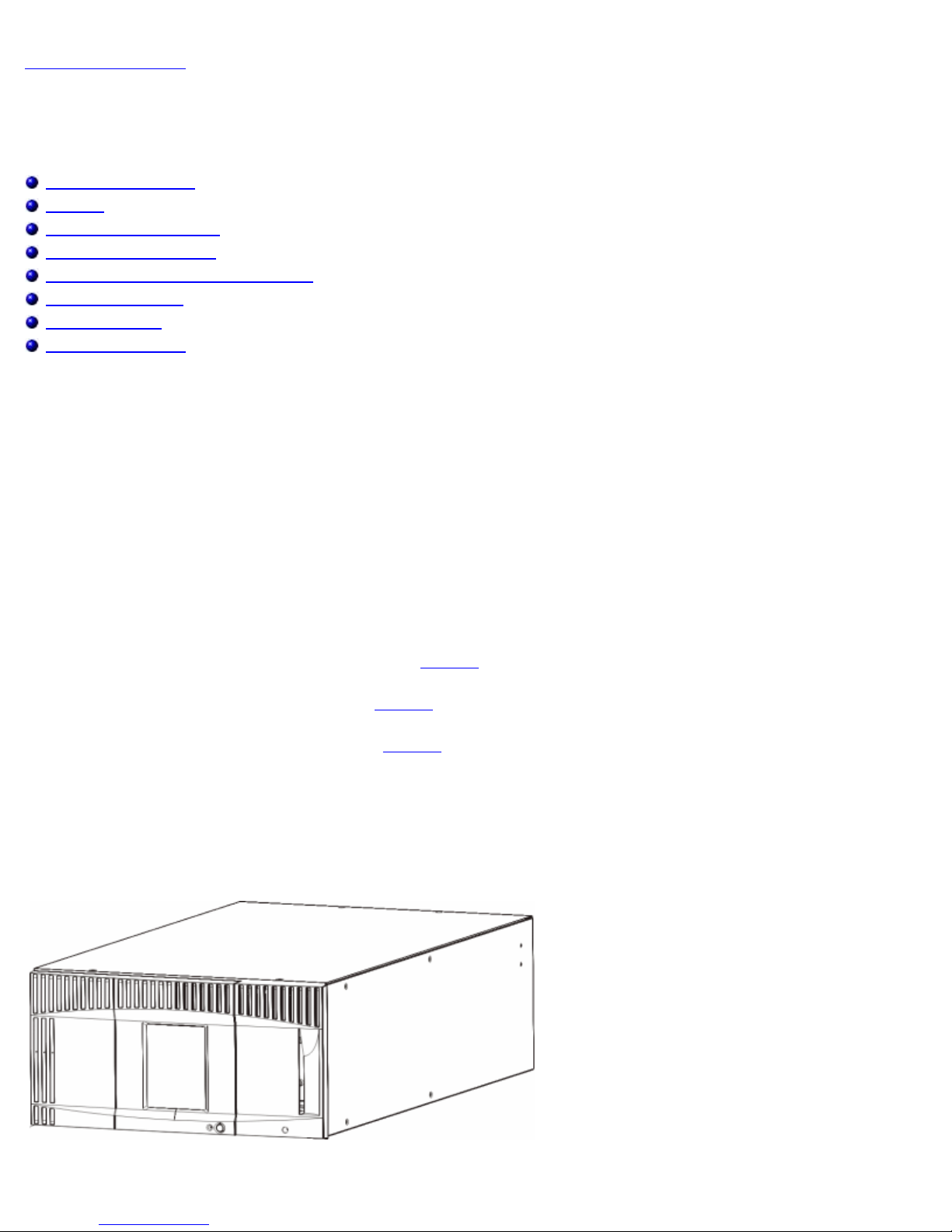
• The ML6010 CM is a 5U Library Control Module.
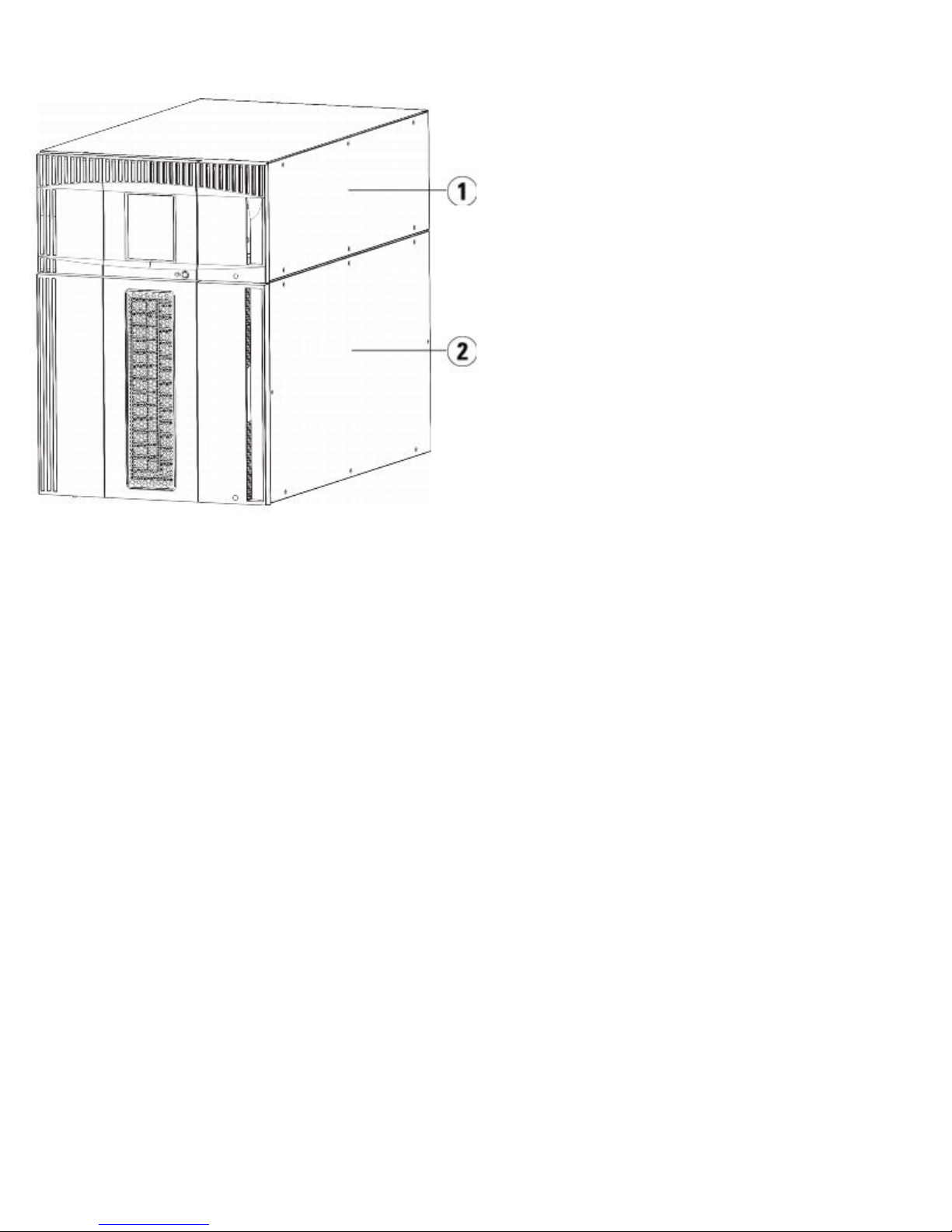
• The ML6020 CM consists of one (1) ML6010 CM 5U Library Control Module and one (1) PowerVault ML6000 EM
9U Library Expansion Module (14U total). Figure 2 shows the front view of the ML6020 CM.
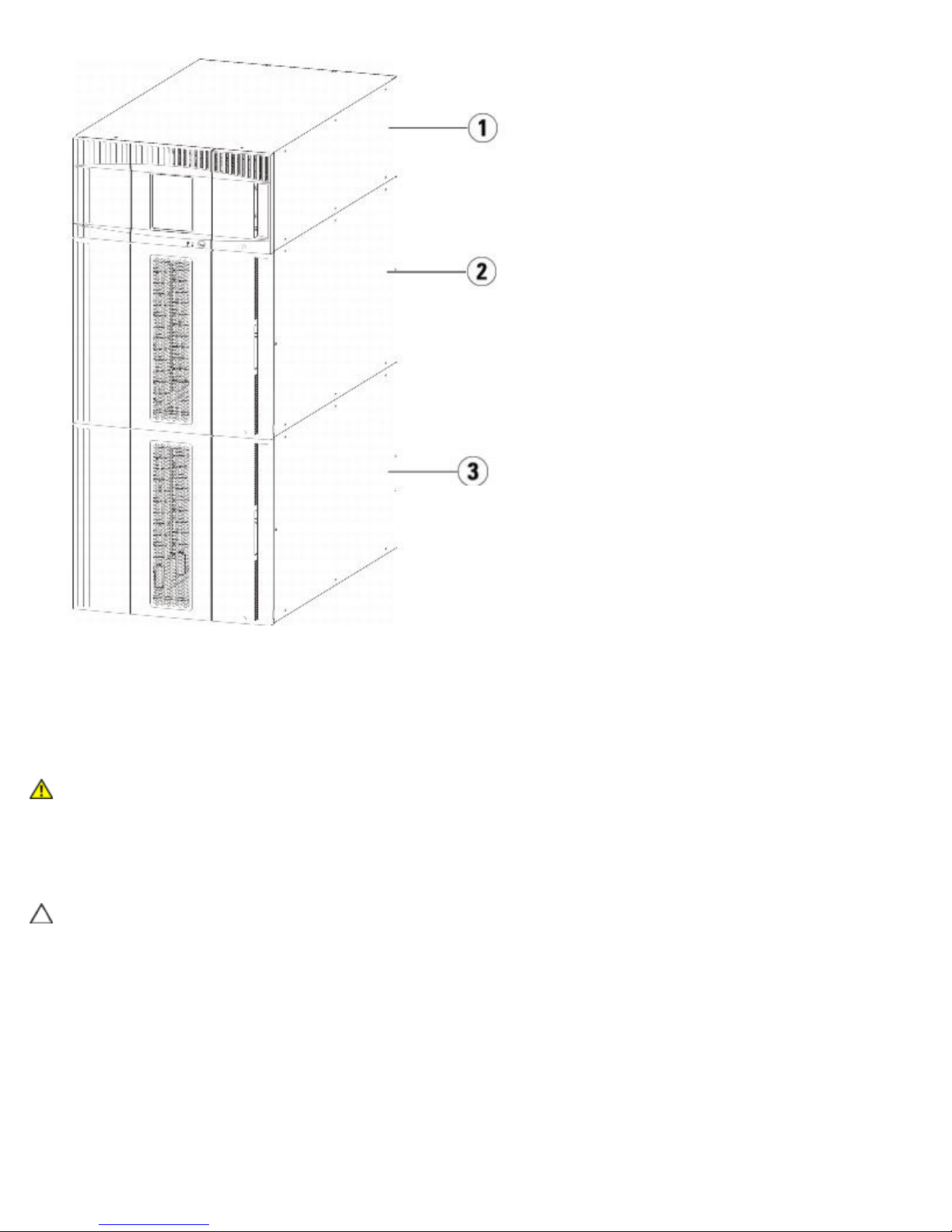
• The ML6030 CM consists of one (1) ML6010 CM 5U Library Control Module and two (2) PowerVault ML6000 EM
9U Library Expansion Modules (23U total). Figure 3 shows the front view of the ML6030 CM.
In addition, the ML6030 CM configuration can be expanded as follows:
• The ML6030 CM plus one (1) PowerVault ML6000 EM 9U Library Expansion Module (32U total)
• The ML6030 CM plus two (2) PowerVault ML6000 EM Library 9U Expansion Modules (41U total)
Figure 1 ML6010 CM Library Configuration (Standalone 5U Library Control Module)
Figure 1 shows the front view of the ML6010 CM.
file:///T|/htdocs/stor-sys/ML6000/en/html/ch02.htm[9/17/2012 1:49:17 PM]
Description
Figure 2 ML6020 CM Library Configuration (5U Library Control Module Plus One 9U Library Expansion
Module)
1 5U Library Control Module
2 9U Library Expansion Module
Figure 3 ML6030 CM Library Configuration (5U Library Control Module Plus Two 9U Library Expansion
Modules)
file:///T|/htdocs/stor-sys/ML6000/en/html/ch02.htm[9/17/2012 1:49:17 PM]
Description
1 5U Library Control Module
2 9U Library Expansion Module
3 9U Library Expansion Module
Warning: All libraries taller than 14U must be installed in a rack having a main protective earthing
(grounding) terminal, and power must be supplied via an industrial plug and socket-outlet and/or an
appliance coupler complying with IEC 60309 (or an equivalent national standard) and having a protective
earth (ground) conductor with a cross- sectional area of at least 1.5 mm2 (14 AWG).
To ensure proper airflow and access space, allow 60 cm (24 inches) in the front and back of the library.
Caution: ML6030 (and higher) CM and Expansion Modules require professional installation. Professional installation
may have been included with your purchase. Please call 1 800 945 3355 to schedule professional installation of your
PowerVault library.
Modules
PowerVault ML6000 libraries are modular, and you can increase the size at any time. The three base systems for the
PowerVault ML6000 library are as follows:
• ML6010 CM (5U rack height)
• ML6020 CM (14U rack height)
• ML6030 CM (23U rack height)
These configurations can be scaled up by adding PowerVault ML6000 EM 9U Library Expansion Modules to a maximum rack
file:///T|/htdocs/stor-sys/ML6000/en/html/ch02.htm[9/17/2012 1:49:17 PM]

Description
height of 41U. 9U Library Expansion Modules provide additional capacity as your storage and tape drive requirements change.
See Figure 4 for an illustration of library scalability. For information on installing, removing, and replacing modules, see
Installing, Removing, and Replacing.
Each module has a specific number of fixed storage slots, I/E station slots, and tape drive slots available. See Library capacity
is as follows. for the number of slots available for each library configurations.
Note: Slot counts in this document do not include five inaccessible slots in the bottom row of any library configuration.
For more information about these slots, see Unused Slots.
Caution: ML6030 (and higher) CM and Expansion Modules require professional installation. Professional installation
may have been included with your purchase. Please call 1 800 945 3355 to schedule professional installation of your
PowerVault library.
5U Library Control Module
The 5U Library Control Module is required in any PowerVault ML6000 library configuration. The 5U Library Control Module
contains the robotic controls, library control blade (LCB), and touch screen display. The 5U Library Control Module also
contains an import/export (I/E) station, fixed storage slots, tape drives, and at least one power supply.
9U Library Expansion Modules
9U Library Expansion Modules are supplementary modules that can be stacked above or below the 5U Library Control Module.
Each 9U Library Expansion Module contains fixed storage slots, tape drive slots, and power supply slots. The I/E stations on
9U Library Expansion Modules are included and may be configured as storage. 9U Library Expansion Modules also contain
bays for optional Fibre Channel (FC) Input/Output (I/O) blades.
If a 9U Library Expansion Module is used only for storage and does not contain tape drives or FC I/O blades, it does not need
a separate power supply. All power is derived from the 5U Library Control Module.
Stackability
The maximum rack height of the library is 41U, which consists of a 5U Library Control Module and four 9U Library Expansion
Modules.
Figure 4 Base Systems Plus 9U Library Expansion Modules
ML6010
slots)
Figure 4 illustrates the stackability of the library.
ML6030 CM + 1 9U Library
(41
ML6020
(133 slots)
ML6030
(225 slots)
Expansion Module
(317 slots)
5U Library
Control Module
ML6030 CM + 2 9U Library
Expansion Modules
(409 slots)
9U Library Expansion Module
5U Library
Control Module
5U Library
Control Module
5U Library
Control Module
5U Library
Control
Module
file:///T|/htdocs/stor-sys/ML6000/en/html/ch02.htm[9/17/2012 1:49:17 PM]
9U Library
Expansion Module
9U Library
Expansion Module
9U Library
Expansion Module
9U Library Expansion Module 9U Library Expansion Module
9U Library Expansion Module 9U Library Expansion Module
9U Library Expansion Module 9U Library Expansion Module
Description
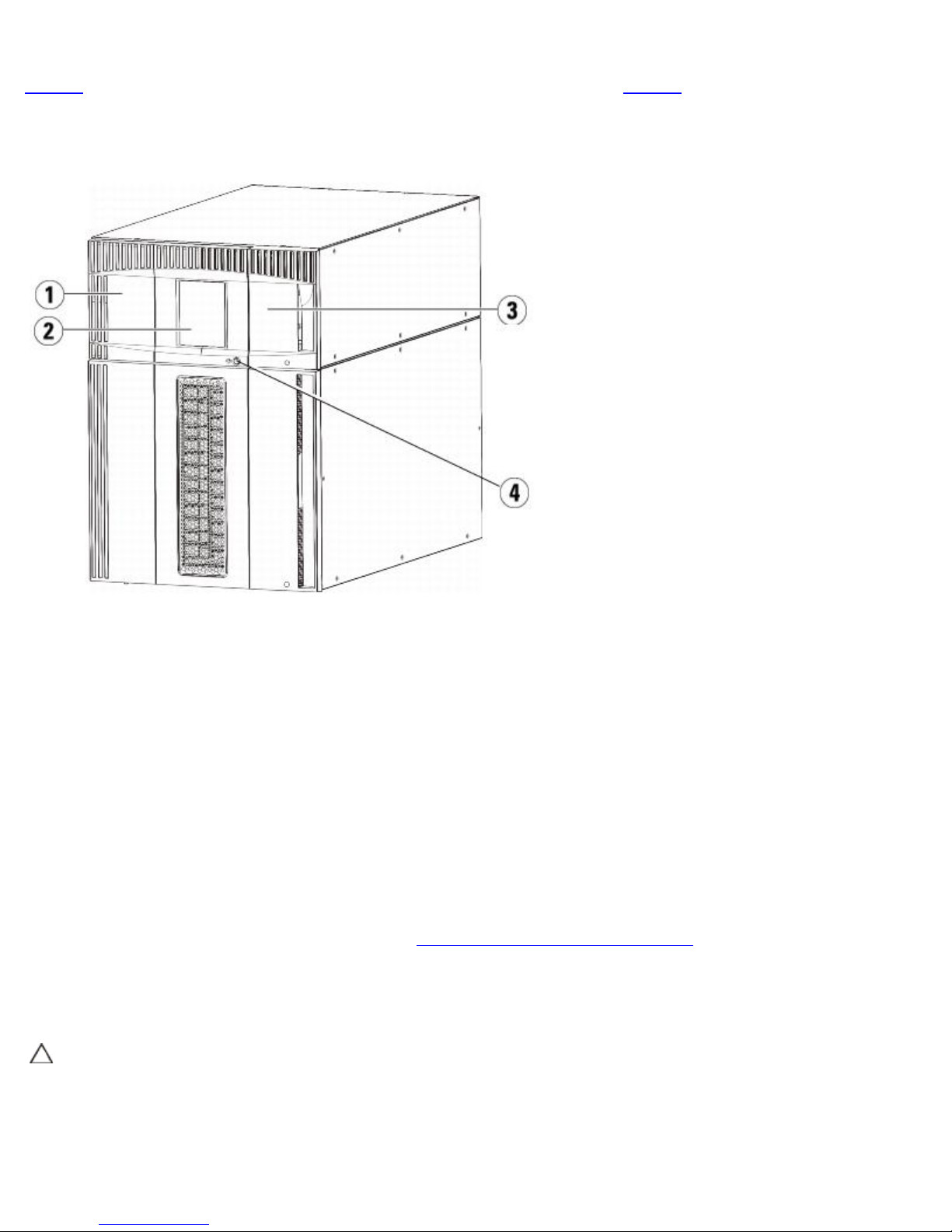
Front Panel Components
Figure 5 shows the front panel components of the library. The paragraphs following Figure 5 describe the components in
detail.
Figure 5 Front Panel Components
1 Access door
2 Operator panel
3 I/E station
4 Front power button
Access Door
The access door allows access to the internal components of the library. Each 5U Library Control Module and 9U Library
Expansion Module has an access door. In most cases, you will not need to access the library through this door except when
you want to bulk load or unload cartridges from the library.
The access door is locked by the I/E station door. To open the access door, you must first open the I/E station door. If you
want to prohibit access to the library, which is recommended for security reasons, lock the I/E station door. This keeps
unauthorized users from accessing tape cartridges.
You can lock and unlock the I/E station door using commands on the Operations menu. If necessary, you can also manually
unlock the I/E station door. For more information, see
If the access door is opened, the library is not available for use. When an access door (on any module) is opened, all inprogress motion commands are stopped, and the picker slowly lowers to the bottom of the library. When the access door is
closed, the library returns any media in the picker to its original slot and also performs a library inventory.
Caution: Care should be taken to avoid opening the access door during robotic operations since the robot will stop
immediately and will fail to complete the current operation.
Locking and Unlocking the I/E Stations.
I/E Station
I/E stations enable importing and exporting cartridges with minimal interruption of normal library operations. I/E stations are
file:///T|/htdocs/stor-sys/ML6000/en/html/ch02.htm[9/17/2012 1:49:17 PM]
Description
located on the front of the 5U Library Control Module and on the front of 9U Library Expansion Modules. A 5U I/E station has a
capacity of six cartridges. A 9U I/E station has a capacity of 12 cartridges.
The I/E stations can also be configured as storage as well as become part of a logical division of library resources known as a
partition. The I/E station is shared among all partitions, but the I/E station slots are owned by one partition at a time. When
an I/E station slot is assigned to a partition, only the assigned partition can access that slot.
Operator Panel
The operator panel is the touch screen display device upon which the graphical user interface (GUI) appears. The operator
panel is located on the access door of the 5U Library Control Module. The library operations and service functions are
performed from this screen. The GUI is also accessible through a remote Web client. For more information on the library user
interfaces, see
Understanding the User Interface.
Front Power Button
Turning off the front power button turns off the robot and operator panel, but power still runs to the power supplies. Use the
front power button to manually shut down the library. See
shut down or restart the library safely.
Shutting Down or Restarting the Library for instructions on how to
Back Panel Components
Figure 6 shows the back panel components of the library. The paragraphs following Figure 6 describe the components in
detail.
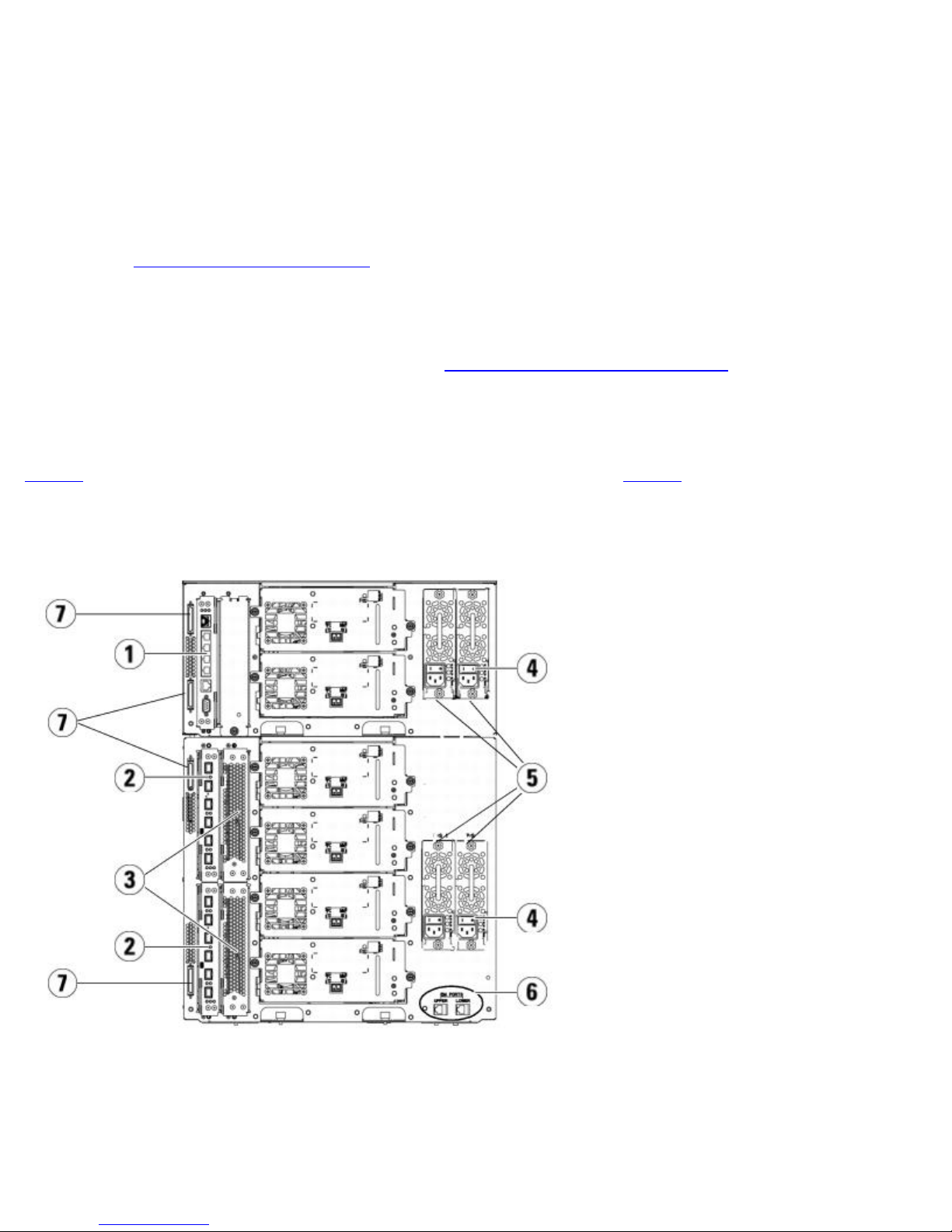
Figure 6 Back Panel Components
1 Library control blade (LCB)
2 FC I/O blade (optional)
3 FC I/O fan blades (required with FC I/O blades)
4 Rear power switch
5 Power supplies
file:///T|/htdocs/stor-sys/ML6000/en/html/ch02.htm[9/17/2012 1:49:17 PM]
Description
6 Upper and lower Ethernet ports on 9U Library Expansion Module
7 Module terminator connectors (CAN bus connectors)
Rear Power Switches
Rear power switches are located on each power supply. Turning off the rear power switch on a power supply removes all
power from the library. The rear power switches should be used in all emergency and service situations.
Warning: Turn off the rear power switch whenever you are servicing the library. In the event of danger to
personnel or property, immediately turn off the rear power switch and remove all power cords.
Caution: Except in emergencies, use the shutdown procedure before switching off the rear power switch. See
Shutting Down or Restarting the Library for instructions on how to shut down the library.
Power System
The library supports single and redundant power configurations. The single power configuration has a single AC line input and
single DC power supply. The redundant configuration has dual AC line input and dual DC power supplies.
If you have redundant power supplies, you can "hot swap" a power supply (power to the library remains on while you
exchange the hardware), and you can "hot add" power supplies to other modules (power to the library remains on while you
are adding the hardware).
Caution: At least one power supply must be plugged in at all times.
Warning: The power outlet must be available near the library and must be easily accessible.
Caution: The 9U Library Control Module and each 9U Library Expansion Module that contains drives must have at
least one power supply for every four drives. You can add a redundant power supply to each module. Installing one
power supply in one module and another power supply in another module does not provide redundant power; the two
power supplies must reside in the same module.
The power system consists of the following components:
• Power supply
• AC power cord
The power supply has three light-emitting diodes (LEDs) that provide status information. These LED status indicators are
green and blue in color.
• Green represents AC OK or DC OK.
• Blue represents swap-mode power status.
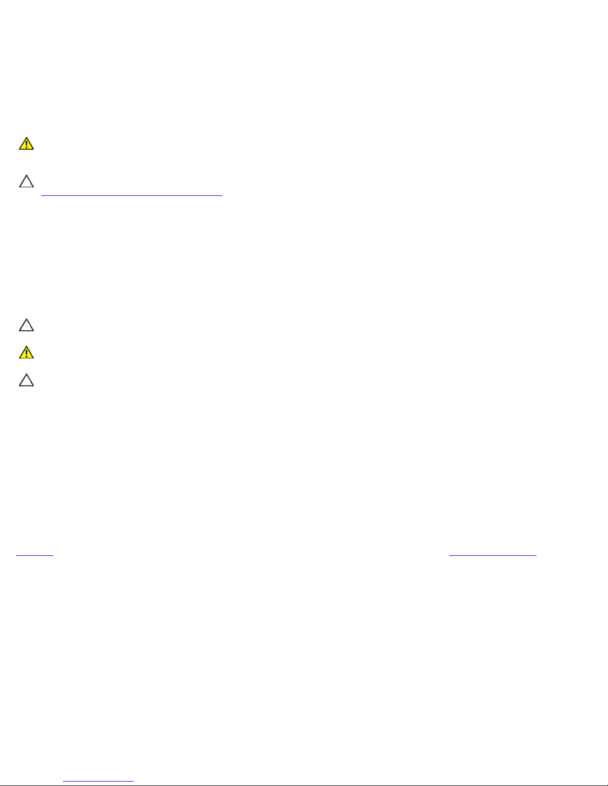
Figure 7 shows the power supply LEDs. For more information on the behavior of the LEDs, see Power Supply LEDs.
Figure 7 Power Supply LEDs
file:///T|/htdocs/stor-sys/ML6000/en/html/ch02.htm[9/17/2012 1:49:17 PM]
Description
1 LEDs
Library Control Blade
The library control blade (LCB) manages the entire library, including the operator panel and picker assembly, and is
responsible for running system tests to ensure that the library is functioning properly. The LCB also provides internal
communication to Fibre Channel (FC) I/O blade slots. The LCB has four Ethernet ports, supporting a total of four FC I/O
blades in the library.
The LCB indicates its status with three LED Reliability, Availability, and Serviceability (RAS) status indicators. These indicators
are green, amber, and blue in color.
• Green represents processor status.
• Amber represents health status.
• Blue represents power-control status.
Figure 8 shows the location of the LCB components, including LEDs. For more information on the behavior of the LCB LEDs,
LCB and FC I/O Blade LEDs.
see
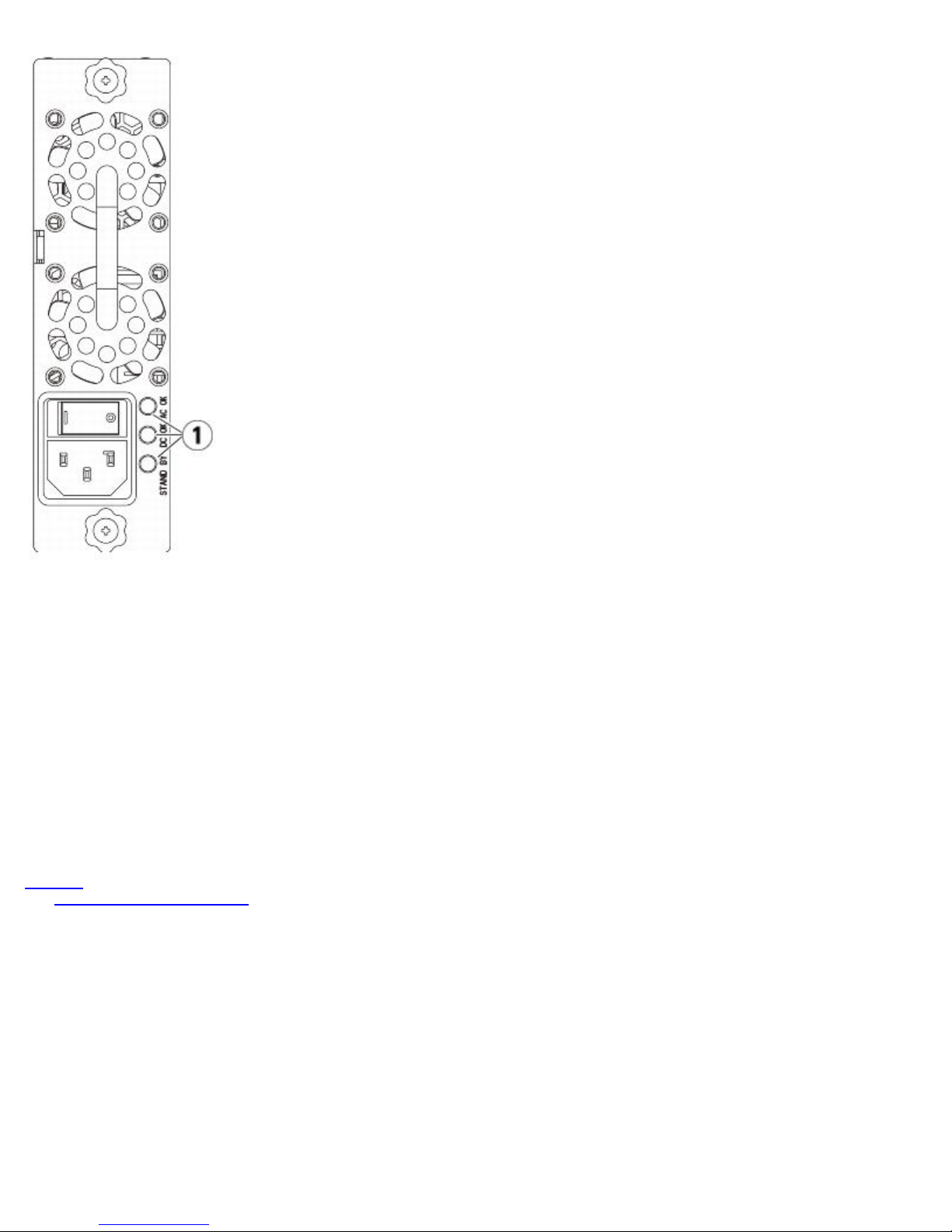
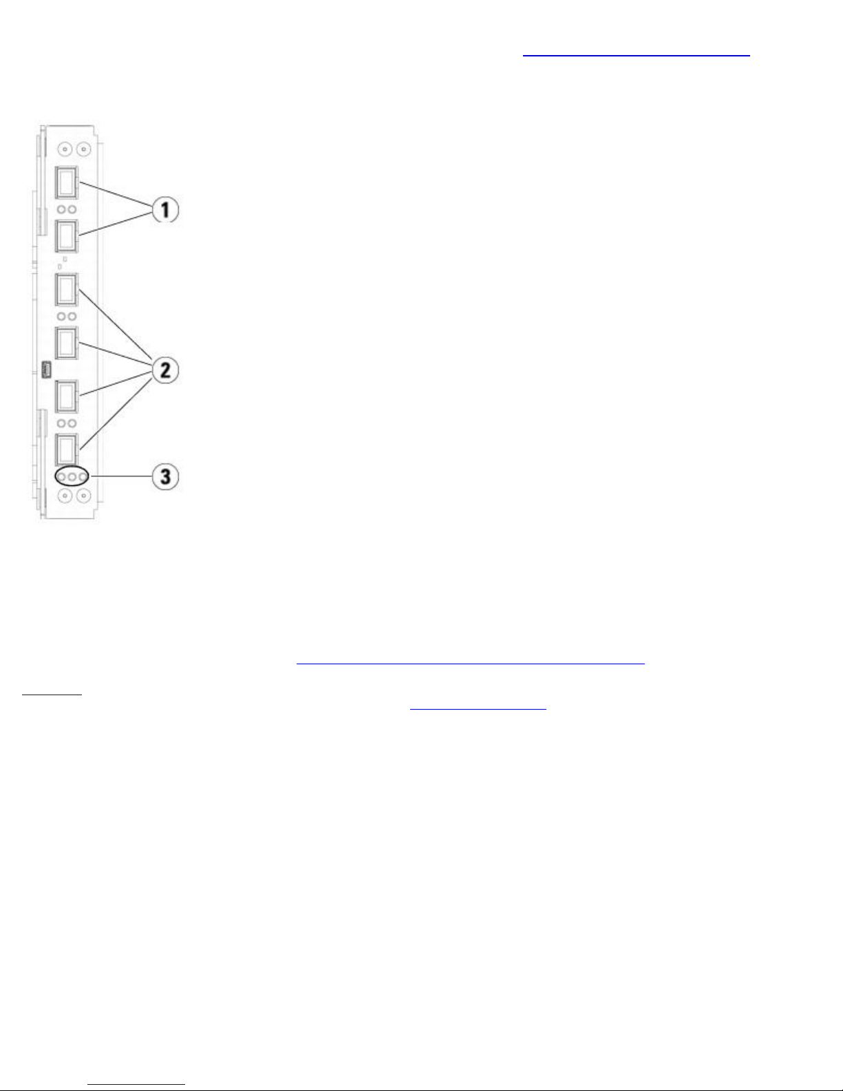
Figure 8 Library Control Blade
file:///T|/htdocs/stor-sys/ML6000/en/html/ch02.htm[9/17/2012 1:49:17 PM]
Description
1 LEDs (blue, amber, green)
2 Gigabit Ethernet (external network) port
3 Ethernet I/O blade control ports (inactive if FC I/O blades are not installed)
4 Service Ethernet port
5 Service serial port
Fibre-Channel input/Output Blades
9U Library Expansion Modules support optional Fibre Channel (FC) input/Output (I/O) blades that provide connections for FC
tape drives in the library. Each FC I/O blade has an embedded controller that provides connectivity and features that enhance
the performance and reliability of tape drive operations. I/O blades also aggregate FC tape drive connections, reducing switch
port and cabling requirements.
Each FC I/O blade has six auto-negotiating, 4 Gb/s FC ports and backplane connections. The FC I/O blade provides two host
communication ports and four connection ports to FC drives. Each FC I/O blade is cooled by a fan blade that is installed next
to the FC I/O blade in the 9U Library Expansion Module. FC I/O blades and fan blades are hot-swappable.
FC I/O blades cannot be installed in the 5U Library Control Module, so your library configuration must include at least one
9U Library Expansion Module to include FC I/O blades. Each 9U Library Expansion Module can house up to two FC I/O blades.
Depending on the number of installed 9U Library Expansion Modules, the library can support from one to four FC I/O blades.
No library configuration can contain more than four FC I/O blades. Any FC drive in the library, including drives in the
5U Library Control Module, can be connected to an FC I/O blade in a 9U Library Expansion Module.
Note: FC I/O menu commands are available for use only when FC I/O blades are installed in the library.
The FC I/O blade indicates its status with three LED status indicators. These indicators are green, amber, and blue in color.
• Green represents processor status.
• Amber represents health status.
• Blue represents power-control status.
Figure 9 shows the FC I/O Blade, including LEDs. For more information on the behavior of the FC I/O Blade LEDs, see LCB
and FC I/O Blade LEDs.
For information on configuring I/O blades, see Working With FC I/O Blades.
file:///T|/htdocs/stor-sys/ML6000/en/html/ch02.htm[9/17/2012 1:49:17 PM]
Description
For information on installing and cabling FC I/O blades and FC tape drives, see Installing, Removing, and Replacing.
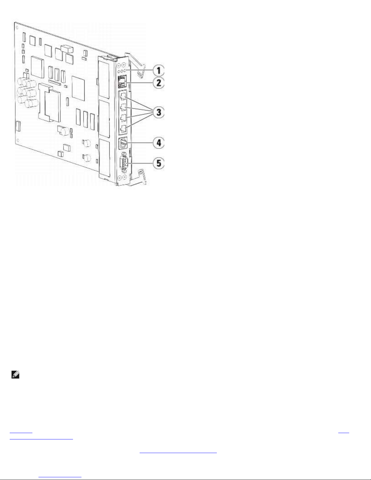
Figure 9 FC I/O Blade
1 FC ports to host(s)
2 FC ports to drive(s)
3 LEDs (blue, amber, green)
Each FC I/O blade is cooled by a fan blade that is installed next to the FC I/O blade in the 9U Library Expansion Module. For
information on installing the fan blade, see Adding, Removing, and Replacing the FC I/O Fan Blade.
Figure 10 shows the FC I/O fan blade, including the LED. The single amber LED represents health status. For more
information on the behavior of the FC I/O fan blade LED, see
FC I/O Fan Blade LED.
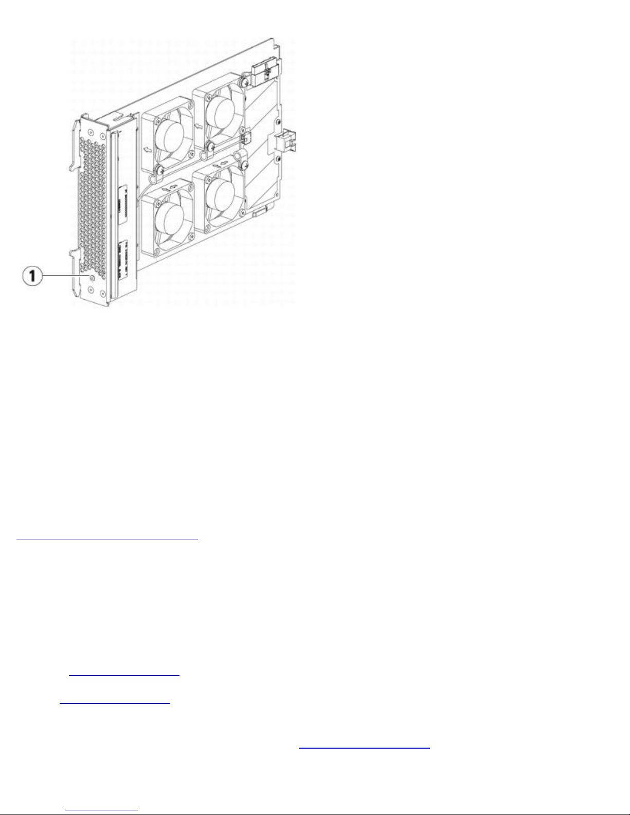
Figure 10 FC I/O Fan Blade
file:///T|/htdocs/stor-sys/ML6000/en/html/ch02.htm[9/17/2012 1:49:17 PM]
Description
1 LED (amber)
Robotic System and Barcode Scanner
The robotic system identifies and moves the cartridges between the storage slots, tape drives, and the I/E station. The
robotic arm (picker) has picker fingers that enable it to grab tape cartridges and move them into positions along X, Y, and Z
motion coordinates. The robotic system and the barcode scanner work together to identify the locations of resources within
the library.
Each tape cartridge must contain a barcode that the barcode scanner reads during the inventory process. During the inventory
process, the barcode scanner reads the fiducial labels to identify the types of magazines and tape drives that are installed in
the library.
Every tape cartridge must have a unique machine-readable barcode attached to it. Tape cartridges cannot have duplicate
barcode labels. This barcode identifies the cartridge. The library stores the physical location of the tape cartridge in an
inventory database. All library or host requests typically reference the location of the tape cartridges based on this barcode
number. Barcode labels are mandatory and must adhere to specific standards. For more information on barcodes, see
Working With Cartridges and Barcodes.
Tape Drive Support
Details about tape drive support include:
• Every library configuration must contain at least one tape drive.
• 5U Library Control Modules can hold a maximum of two tape drives.
• 9U Library Expansion Modules can hold a maximum of four tape drives.
Please see
The library supports mixing different tape drive types within the library and within partitions. For information on how to do
this, see Working With Partitions.
Supported Components for a list of tape drives and media supported by the PowerVault ML6000 library.
SCSI and SAS tape drives are attached directly to the host. FC tape drives can be directly attached to hosts or to the Storage
Area Network (SAN). FC tape drives can also be attached to FC I/O blades, which manage communication between the hosts
and the drives. For more information on FC I/O blades, see
Tape drives are installed into tape drive slots in the rear of the library. If a tape drive slot is empty, a filler plate covers the
file:///T|/htdocs/stor-sys/ML6000/en/html/ch02.htm[9/17/2012 1:49:17 PM]
Working With FC I/O Blades.

Description
empty tape drive slots to prevent debris from entering the library. Tape drives are shipped filling the tape drive slots from the
bottom to the top of the library, but the tape drives can be reinstalled in any available tape drive slot.
Note: Tape drive filler plates must be in place for the library to operate at normal speed.
For information on adding tape drives, see
Adding a Tape Drive.
Library Features
This section describes several features of PowerVault ML6000 libraries.
User Interface
The operator panel is located on the front door of the 5U Library Control Module and allows you to work locally on the library
via the user interface. The Web client allows you to view and perform library functions from remote sites and is accessible
through a browser. The operator panel and Web client contain a similar user interface and functionality.
Understanding the User Interface for more information about the operator panel and the Web client.
See
Partitions
Partitions are virtual sections within a library that present the appearance of multiple, separate libraries for purposes of file
management, access by multiple users, or dedication to one or more host applications.
Organizing the library into partitions divides the resources into virtual sections. Partitions can be used to control access to
portions of the library by granting permissions to user accounts to access certain partitions.
For more information on partitions, see
Working With Partitions.
Control Path Modification
The control path tape drive is used to connect a partition to a host application. Only one tape drive can be selected as the
control path at one time. For more information, see
Working With Control Paths.
Support for WORM
PowerVault ML6000 tape libraries support WORM (write once, read many) technology in LTO-3, LTO-4, and LTO-5 tape drives.
WORM allows non-rewriteable and non-erasable data to be written and provides extra data security by prohibiting accidental
data erasure. The WORM feature is supported whenever you use WORM cartridges.
Licensable Features
In addition to the standard features, the following additional, licensable features are available for the PowerVault ML6000:
• Advanced Reporting, described in
• Capacity on Demand, described in
• Encryption Key Management, described in
If you purchase these features with your library, the license will be installed when you receive the library. If you upgrade or
add new features after the initial purchase, you will need to obtain and install a license key. For information on how to obtain
and install a license key, see
Obtaining and Installing a License Key.
Advanced Reporting
Capacity on Demand
Encryption Key Management
Back to Contents Page
file:///T|/htdocs/stor-sys/ML6000/en/html/ch02.htm[9/17/2012 1:49:17 PM]

Understanding the User Interface
Back to Contents Page
Understanding the User Interface: Dell™ PowerVault™
ML6000 Tape Library User's Guide
Common User Interface Elements
Operator Panel
Web Client
Menu Trees
User Privileges
User Access
The user interface of PowerVault ML6000 libraries is available in two formats: the operator panel and the Web client.
Operations on the library can be performed locally on the 5U Library Control Module using the operator panel or remotely on
your computer using the Web client. Similar functionality with common elements is used for both formats.
Both the Web client and operator panel user interfaces are required to operate the library. Some functionality is only available
through the Web client, and some functionality is only available through the operator panel. However, using the Web client
rather than the operator panel to perform library operations (when possible) is recommended.
Caution: Do not perform inventory operations (for example, working with RAS tickets, creating/modifying/deleting
partitions) while the library is performing an inventory. Doing so may result in inventory discrepancies, such as missing
tape cartridges.
Common User Interface Elements
The user interface consists of the following areas:
• Header — appears on every screen and contains the company logo, product name, and the three main navigation
buttons. The main navigation buttons are:
• Home — Home page.
• Help — Context-sensitive Help for the active screen.
• Logout — Ability to log out.
•
Title Bar/Menu Tabs (operator panel)
the library/partition name and access to the menu tabs on the main screen. On all other screens, this area
is a single bar and provides the screen name.
• Menu Bar (Web client)— Lists the menu choices.
• Main — Main content area of the screen.
• Health/Navigation — provides information about the "health" of the library by means of three subsystem status
buttons: Library, Drives, and Media. See
subsystem buttons.
— This area appears below the header. On the home page, it provides
System Summary and Subsystem Status for more information on the
Note: A message in the header alerts you when the robot is not ready to perform library functions. See
Troubleshooting "Library Not Ready" Messages for more information on "Library Not Ready" messages displayed in the
header.
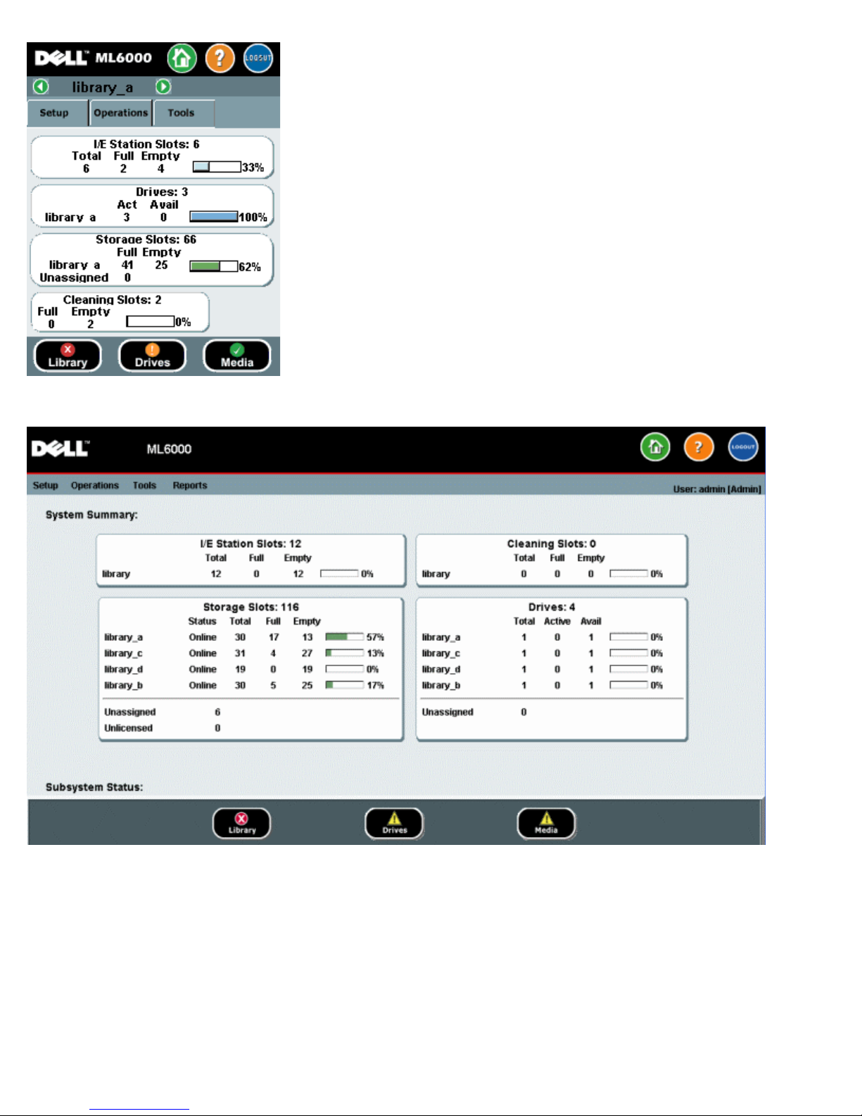
Figure 1 and Figure 2 show the operator panel and the Web client interfaces.
Figure 1 Operator Panel User interface
file:///T|/htdocs/stor-sys/ML6000/en/html/ch03.htm[9/17/2012 1:49:22 PM]
Understanding the User Interface
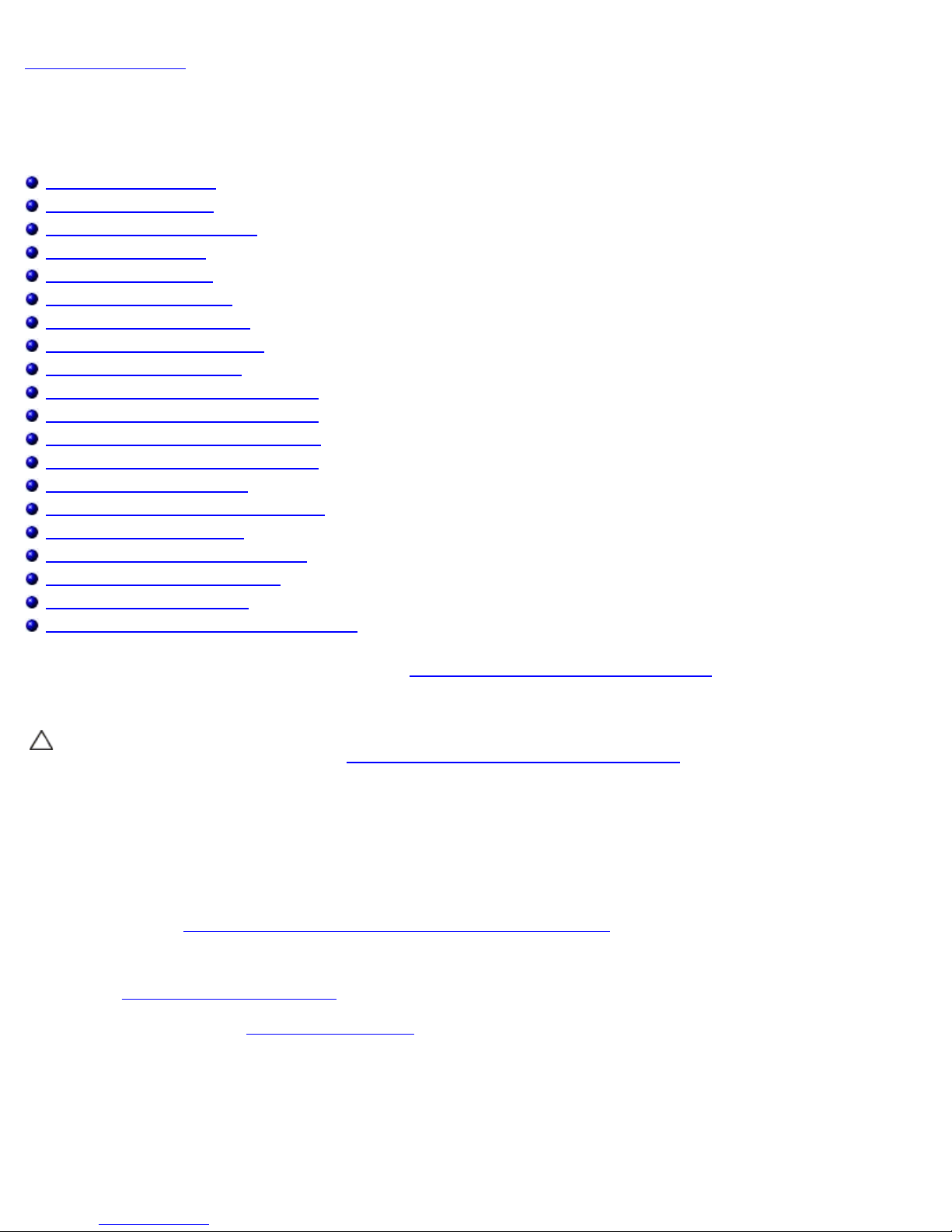
Figure 2 Web Client User interface
System Summary and Subsystem Status
You can quickly gauge the health of the library by observing the color of the three subsystem status buttons located at the
bottom of the home page. These buttons provide quick access to information about the "health" of the library for faster
recovery if problems occur. You can select the buttons to view Reliability, Availability, and Serviceability (RAS) tickets that
report problems in the subsystems.
The three subsystems are:
• Library — This subsystem represents connectivity, control, cooling, power, and robotics.
• Drives — This subsystem represents tape drive components, such as tape drives, tape drive firmware, and tape drive
sleds.
file:///T|/htdocs/stor-sys/ML6000/en/html/ch03.htm[9/17/2012 1:49:22 PM]

Understanding the User Interface
• Media — This subsystem represents media components, such as cartridges and barcode labels.
Each subsystem button will be in one of three states indicated by color. The three states are:
• Green — No RAS tickets exist for this subsystem, or, if any tickets do exist, they have all been closed.
• Yellow — The library contains open or unopened, low-severity (Severity 3) or high-severity (Severity 2) RAS tickets
for this subsystem.
• Red — The library contains open or unopened urgent (Severity 1) RAS tickets for this subsystem.
If the color of a subsystem button is red or yellow, you can click the button to display the corresponding RAS Tickets screen.
This screen lists library, drives, or media RAS tickets, depending on which button was selected. RAS tickets display in order of
last occurrence of each event, starting with the most recent.
Note: Last Occurrence indicates the last time a ticket event occurred. This information updates any time the event
recurs. Last Occurrence does NOT update if you open, close, or resolve the RAS Ticket.
You can change the order in which the RAS tickets are displayed by clicking any header item (for example, Severity, Last
Occurrence, or Name).
On the Web client, you can view closed tickets by selecting the Include Closed Tickets checkbox.
You can also open the All RAS Tickets screen by selecting Tools > All RAS Tickets. See
information about RAS tickets.
About RAS Tickets for more
Home Page
The home page is common to both the operator panel and the Web client. The home page displays the library Capacity
View.
Capacity View
The Capacity View provides tabular data on the capacity of the library's partitions, slots, and drives. You can use the Capacity
View to see a quick summary of the capacity of the library. You can also see which partitions are online (in the Storage Slots
section). The current user's login privileges determine the information that is displayed in the Capacity View.
Details about Capacity View include:
• On the Web client, users see the partitions (in alphabetical order) to which they have access.
• On the operator panel, if users have access to more than one partition, they can navigate to other partitions using the
arrows next to the partition name in the title bar at the top of the screen.
For more information about user privileges, see User Privileges and Working With User Accounts.
Operator Panel
The operator panel is physically attached to the front door of the 5U Library Control Module. The user interface appears on the
touch-screen LCD display of the operator panel for executing basic library management functions. Audible feedback, or "key
click" sounds, are generated when a user presses a button on the operator panel. Users can choose to disable the audible
feedback. See
Configuring System Settings.
Operator Panel Keypads
When a user touches a text box requiring data entry, a keypad screen appears. The alpha, numeric, or month keypad
appears, depending on the type of input field touched. All alphabetic character entries are lower case. The text box appears at
the top of screen, and the numbers/characters appear as they are entered. Pressing 123 opens the numeric keypad.
Operator Panel Indicates Intervention Required
The operator panel lights up (screen saver turns off) if intervention is required. For example, the operator panel lights up
following an import of tapes into the I/E station so that the operator sees the prompt to assign tapes to a partition.
file:///T|/htdocs/stor-sys/ML6000/en/html/ch03.htm[9/17/2012 1:49:22 PM]

Understanding the User Interface
• Receiver Addresses
Web Client
The Web client user interface is similar to the operator panel user interface. The Web client interface is accessible from
supported Web browsers. See
To manage the library from a remote location, you must set up the library's initial network configuration from the operator
panel touch screen. See Configuring Library Security Settings for information on setting the network configuration settings for
remote use.
You must disable Web browser popup blockers to use the Web client interface and the library's online Help. Add the
PowerVault ML6000's Internet Protocol (IP) address to the list of trusted/allowed sites on your PowerVault ML6000-supported
browser, so the Web client pages will automatically refresh.
System Requirements for information about supported browsers.
Note: Do not use your internet browser Back button to navigate the Web client pages. Instead, use the buttons
provided within the Web client.
Note: Log out of the library before closing the internet browser window when you are using the Web client. If you do
not log out, the session will remain open.
Menu Trees
The following menus organize operations and commands into logical groupings:
• The Setup menu consists of commands that administrators can use to set up and configure various aspects of the
library, including partitions, I/E station slots, cleaning slots, control paths, network settings, drive settings, users,
notifications, date and time, licenses, FC I/O blades, and e-mail.
• The Operations menu consists of commands that enable users to change the library's mode of operations, import and
export cartridges, load and unload tape drives, move media, perform diagnostics, and log off. Administrators can also
access commands to lock or unlock the I/E station and to shut the library down.
• The Tools menu consists of commands that you can use to maintain your library, such as viewing RAS Tickets,
generating diagnostic logs, identifying drives, configuring the internal network, saving and restoring the library
configuration, setting system and security settings, and updating firmware.
• The Reports menu (Web client only) consists of summaries of library information.
The menus vary somewhat between the Web client and operator panel user interfaces. Administrators have access to all
menu commands; users with user privileges have more limited access.
Table 1 lists the Web client menus. Some menu commands are available only to administrators.
I/O blade menu items are available for libraries that contain I/O blades.
Table 1 Web Client Menus
Setup Menu* Operations Menu Tools Menu* Reports Menu
• Setup Wizard
• Partitions
• Cleaning Slots
• I/E Station Slots
• Drive Settings
• Control Path
• License
• Notifications
• E-mail Configuration
• Advanced Reporting (if
licensed)
• Media
• Move
• Import
• Export
• Cleaning Media
• Import
• Export
• Partitions
• Change Mode
• Drive
• Load
• All RAS Tickets
• Capture Snapshot
• Save/Restore
Configuration
• E-mail Configuration
Record
• Save Configuration
Record
• Identify Drives
• Drive Operations
• Download SNMP MIB
• IO Blade Info**
• System Information
• Library Configuration
• Network Settings
• Logged in Users*
• All Slots
• Log Viewer*
• Advanced Reporting*
• Drive Resource Utilization
• Media Integrity Analysis
• About
file:///T|/htdocs/stor-sys/ML6000/en/html/ch03.htm[9/17/2012 1:49:22 PM]

Understanding the User Interface
• IO Blade Port Info**
• Media Security
• RAS
• Receiver Addresses
• Contact Information
• Network Management
• Network
• SNMP
• SNMP Trap Registrations
• Unload
• Change Mode
• I/E Station
Lock/Unlock*
• System Shutdown*
• Logout
• Update Library
Firmware
• Reset Factory Defaults
• Diagnostics
• User Management
• User Accounts
• Remote Authentication
• IO Blades**
• Port Configuration
• Channel Zoning
• Host Mapping
• Host Management
• Host Port Failover
• Data Path Conditioning
• I/O Blade Control
• Encryption (if licensed)
• System Configuration
• Partition Configuration
• System Settings
• Date & Time
*Administrators only. **Available only when the library contains I/O blades.
Table 2 lists the operator panel menus. Some menu commands are available only to administrators. I/O blade menu items
are available for libraries that contain I/O blades.
Table 2 Operator Panel Menus
Setup Menu
• Partition Mgmt
• Create Partition
• Delete Partition
• Configure I/E Station Slots
• Configure Cleaning Slots
• User Mgmt
• Create User
• Modify User
• Drive Settings
a
Operations Menu Tools Menu
• Move Media
• Import Media
• Export Media
• Import Cleaning Media
• Export Cleaning Media
• Change Partition Mode
• Load Drive
• Unload Drive
• Change Drive Mode
•
All RAS Tickets
•
Capture Snapshot
•
Drive Mgmt
• Create a firmware tape
• Update drive firmware from tape
• Erase a firmware tape
• Clean drive
• Reset drives
a
a
a
• Drive Info
file:///T|/htdocs/stor-sys/ML6000/en/html/ch03.htm[9/17/2012 1:49:22 PM]

Understanding the User Interface
• Fibre
•
a
• SCSI
• SAS
• Notification
• E-mail Alerts
• E-mail Account
• Customer Contact
• Licenses
• Date & Time
• Network Mgmt
• IP version 4
• IP version 6 (if enabled)
• Port Settings
• Control Path
Lock/Unlock I/E Station
•
Shutdown
a
• About Library
• Network Info
• View Drive Info
• Partition Info
•
Internal Network
a
• System Settings
• User Session Timeout (minutes)
a
• Touch Screen Audio
• Unload Assist
• Logical SN Addressing
• Manual Cartridge Assignment
• Disable Remote Service User
a
a
a
a
• Enable SSL
• Enable SNMP V1/V2
• Enable IPv6
• Enable SMI-S
• Unlabeled Media Detection
•
IO Blades
b
• Port Configuration
• Channel Zoning
• Host Mapping
c
• Host Management
• Host Port Failover
• Data Path Conditioning
• Blade Control
Security
a
• Network Interface
• SSH Services
• ICMP
c
• Remote UI
• SNMP
• SMI-S
Display Settings
• Brightness
• Contrast
• Defaults
•
Library Tests
a
• Installation & Verification Tests
• Library Demo
• View Last Summary Log
• View Last Detailed Log
• E-mail Last Detailed Log
•
Blade Info
b
• Port Info
•
Command History Log
•
Factory Defaults
ab
a
a
Administrators only.
file:///T|/htdocs/stor-sys/ML6000/en/html/ch03.htm[9/17/2012 1:49:22 PM]
b
Available only when the library contains I/O blades. cVisible only when host mapping has been

Understanding the User Interface
enabled.
User Privileges
User privilege levels are manually assigned to user accounts created within the library. Controlling access to screens and
operations within the library preserves the integrity of the library and the data that is stored in it. See
Accounts for more information on setting user privilege levels.
Two types of users are defined in PowerVault ML6000 libraries:
• Administrators have access to the entire physical library and all of its partitions, and can configure the library and
set up user and administrator accounts. The library ships with a default administrator account. The user name for the
default administrator account is admin and the password is password. You cannot modify or delete the user name for
the default administrator account, but you can modify the password. If you misplace the password for the default
administrator account, contact Dell Technical Support (see
• Users have access to one or more assigned partitions, as well as portions of the Operations and Reports menus.
Users cannot access the Setup and Tools menus. Users can perform functions within a partition (such as performing
cartridge and tape drive operations), but cannot set up or configure the library (for example, creating or deleting
partitions).
Details on user privileges include:
• The library can contain eighteen user accounts (user or administrator or both), including the default administrator
account.
• Eighteen user (user or administrator or both) sessions can be active at one time.
• The same user can be logged in to a library from multiple remote locations.
• Clicking the close button (X) in the upper-right corner of the Web client closes the browser window but does not log
the user or administrator out.
• All users are logged out automatically after a configurable period of inactivity. The default user session timeout period
is 30 minutes, but administrators can change the user session timeout to a value from 15 minutes to 480 minutes
(eight hours). See
• A screen saver is invoked after 10 minutes of inactivity on the operator panel. After an hour of inactivity, the screen
will appear black. If the user has not been logged out for inactivity, touching the operator panel will reactivate it,
returning the user to the screen last in use. (The Web client does not use a screen saver.)
• An administrator can disable any access to the library from the Web client. For more information, see Configuring
System Settings.
Configuring System Settings.
Contacting Dell).
Working With User
User Access
Administrators have access to the entire library. Users with user privileges can only access some of the menus. See Table 1
for the Web client menu tree and privilege level information. See
information.
Back to Contents Page
file:///T|/htdocs/stor-sys/ML6000/en/html/ch03.htm[9/17/2012 1:49:22 PM]
Table 2 for the operator panel menu tree and privilege level
Configuring Your Library
Back to Contents Page
Configuring Your Library: Dell™ PowerVault™ ML6000
Tape Library User's Guide
About the Setup Wizard
Using the Setup Wizard
Logging On to the Web Client
Managing the Network
Working With Partitions
Configuring Cleaning Slots
Configuring I/E Station Slots
Setting Tape Drive Parameters
Working With Control Paths
Obtaining and Installing a License Key
Setting Customer Contact Information
Configuring the Library E-mail Account
Working With RAS E-mail Notifications
Working With User Accounts
Setting the Date, Time, and Time Zone
Working With FC I/O Blades
Configuring Library Security Settings
Configuring the Internal Network
Configuring System Settings
Configuring Operator Panel Display Settings
Once you have installed the hardware as described in
your library's settings. A Setup Wizard helps you get started configuring your library, and menu commands on both the
operator panel and the Web client allow you to reconfigure your library at any time.
Setting Up the PowerVault ML6000 Library, you are ready to configure
Caution: Always save the library configuration after modifying configurable items. This will allow you to restore the
most current settings if necessary. See Saving and Restoring the Library Configuration.
About the Setup Wizard
When you first power on the library, the operator panel displays the Setup Wizard, which walks you through the initial
configuration of the library's basic operational settings.
The Setup Wizard on the operator panel only runs once, at initial startup. After that, administrators access the Setup Wizard
any time via the Web client or use commands on the Setup and Operations menus to modify all library settings, including
network settings. See
While completing the Setup Wizard at initial startup is recommended, you may need to begin using the library locally
immediately. In this case, you can cancel out of the Setup Wizard and allow the library to run on the default configuration
settings. See
For additional information, see Using the Setup Wizard.
Default Configuration Settings.
Using the Default Administrator Account
When you power on the library for the first time, you do not need to log in to use the operator panel. You can start using the
Setup Wizard immediately. After the initial setup session on the operator panel, however, you will need to log in to the
operator panel as well as the Web client.
Completing the Library Configuration With Menu Commands.
file:///T|/htdocs/stor-sys/ML6000/en/html/ch04.htm[9/17/2012 1:49:29 PM]

Configuring Your Library
The library ships with a default administrator account. The user name on the account is admin and the password is
password. When you see the Login screen on the operator panel or Web client, type admin in the User Name text box and
password in the Password text box. As soon as the initial setup is complete, you should change the password on the default
administrator account. For information on changing passwords, see
Modifying Local User Accounts.
Note: You cannot delete the default administrator account or modify the user name. You can, however, change the
password.
Note: If you misplace the password for the default administrator account, contact Dell Technical Support (see
Contacting Dell).
Completing the Library Configuration With Menu Commands
The Setup Wizard is an aid to assist you with the initial configuration of the library. The Setup Wizard, however, contains only
a subset of configuration tasks. The operator panel tabs and Web client menus provide access to all configuration options that
are included in the Setup Wizard and many that are not. Once the initial Setup Wizard session is complete, administrators can
choose whichever method is most convenient or necessary for modifying library settings.
The following topics cover using the Setup Wizard as well as Setup and Operations commands to configure the library. Paths
to open the appropriate screens on both the operator panel and the Web client are given for each task. For the operator
panel, the paths refer to the navigation tabs at the top of the home page. For the Web client, the paths refer to the menus.
For the menu trees on both the operator panel and Web client, see
Menu Trees.
Note: Power cycling (powering the library on and off) is not necessary to configure the library.
Using the Setup Wizard
The Setup Wizard simplifies the process of configuring the library. When you first power on the library, the operator panel
displays the Setup Wizard. After that, you can no longer access the Setup Wizard from the operator panel. You can always
access the Setup Wizard from the Setup menu on the Web client.
The recommended procedure for using the Setup Wizard for the initial configuration is as follows:
1 Turn on the library and begin using the Setup Wizard on the operator panel.
2 Work through all of the screens as prompted (see Setup Wizard Tasks).
3 When you get to the network configuration screens, configure the network settings as follows:
Note: You cannot log into the Web client until you have configured the network settings.
• If you are using IPv4: On the Setup Wizard: Enable IPv6 screen, do NOT select the Enable IPv6 checkbox.
Click Next. Configure the network settings.
• If you are using IPv6: On the Setup Wizard: Enable IPv6 screen, select the Enable IPv6 checkbox and click
Next. You have enabled IPv6 but you will not be prompted to configure IPv6 settings here. Continue with the
Setup Wizard screens. Then, when you are finished using the Setup Wizard, configure the IPv6 network settings
by going to Setup > Network Mgmt on the operator panel.
4 Log out of the operator panel.
5 Using the default administrator account, log in to the Web client. Type admin in the User Name text box and
password in the Password text box.
6 Complete the Setup Wizard screens on the Web client interface. The final Setup Wizard screen will prompt you to
apply your settings.
When you have completed the Setup Wizard, the Library Configuration report appears on the Web client. The Library
Configuration report provides information on the library's tape drives, partitions, I/E stations, storage slots, cleaning
slots, and loaded media. See
report.
Viewing the Library Configuration for more information on the Library Configuration
Note: Depending on the size of the library, there may be a slight delay after you apply the settings in the Setup
Wizard while the Library Configuration report page loads.
file:///T|/htdocs/stor-sys/ML6000/en/html/ch04.htm[9/17/2012 1:49:29 PM]

Configuring Your Library
Details on using the Setup Wizard include:
• The only time that you do not need to log in to the library is when the Setup Wizard appears on the operator panel the
first time the library is powered on.
• After a timeout period of one hour, the Setup Wizard will close, and you will be logged out of the library. Use the
default administrator account to log in to the operator panel.
• If you time out of the Setup Wizard or do not complete all the Setup Wizard screens, the library will apply the default
configuration settings plus whatever modifications you made (see
• You cannot log in to the library from the Web client until you have configured network settings on the operator panel.
To change IPv4 settings and configure IPv6 settings, go to Setup > Network Mgmt.
• You can return to the Setup Wizard from the Web client.
• Any administrators you create will also be able to use the Setup Wizard from the Web client as well as Setup and
Operations menu commands to reconfigure the library.
• If necessary, you can cancel out of the Setup Wizard on the operator panel and begin using the library locally with
the default settings in place. If you accept the default network configuration settings, you will not be able to access the
library remotely from the Web client. You can, however, use Setup > Network Mgmt on the operator panel at any
time to modify network settings. See
Default Configuration Settings for more information.
Default Configuration Settings).
Default Configuration Settings
The default configuration settings are as follows:
• License keys: COD, 41 slots minimum. The total number depends on number of pre-activated slots purchased.
• Network settings: DHCP enabled, IPv6 disabled
• Import/export (I/E) station slots: 6
• Cleaning cartridge slots: 0
• Partitions: By default, the library creates partitions and assigns available library resources proportionately among
the partitions, grouping tape drives according to distinct combinations of tape drive interface type (SCSI, FC, or
SAS) and tape drive media type. To mix tape drive types/media types within a partition, create partitions
See also
manually. See
About the Setup Wizard above.
Manually Creating Partitions.
Setup Wizard Tasks
As you work through the Setup Wizard screens, follow the on-screen instructions.
The Setup Wizard screens contains only a subset of all configuration options. The Setup
most configuration options, including those in the Setup Wizard. This section includes detailed descriptions of the
configuration tasks, including how and when to access them through the Setup and Operations menus.
• Welcome (operator panel) — Welcomes you to the Setup Wizard.
• Hardware Installation (operator panel) — Reminds you to install tape drives and the Ethernet cable.
•
Setting the Date, Time, and Time Zone (operator panel and Web client) — Allows you to set the date and time on your
library.
• Managing the Network (operator panel) — Allows you to configure your IPv4 network settings for remote access using
the Web client. Allows you to enable IPv6 so that you can configure IPv6 network settings later using Setup >
Network Mgmt.
Applying a License Key (operator panel and Web client) — Allows you to enter keys for licensed features. For more
•
information, see
•
Configuring Cleaning Slots (operator panel and Web client) — Allows you to configure dedicated cleaning slots.
Configuring at least one cleaning slot enables the AutoClean feature.
• Configuring I/E Station Slots (operator panel and Web client) — Allows you to configure import/export (I/E) station
slots.
• Working With Partitions (operator panel and Web client) — Allows you to set the number of library partitions.
• Confirm Settings (operator panel and Web client) — Allows you to confirm your library settings.
Obtaining and Installing a License Key.
and Operations menus contain
file:///T|/htdocs/stor-sys/ML6000/en/html/ch04.htm[9/17/2012 1:49:29 PM]
Configuring Your Library
Caution: Always take a library snapshot and save the library configuration after modifying configurable items. If
modifying items results in issues, the library snapshot will help technical support personnel to troubleshoot the
problem. Saving the library configuration will allow you to restore the most current settings if necessary. For more
information on taking a library snapshot and saving and restoring the library configuration, see
the Library Configuration.
Saving and Restoring
Note: Setup Wizard operations cannot be performed concurrently by multiple administrators logged in from different
locations. You can access the screens, but you cannot apply changes while another administrator is performing the
same operation.
The paths to open the appropriate screens are as follows:
• From the Web client, select Setup > Setup Wizard.
• From the operator panel, the Setup Wizard is available only upon first power-on of library.
Logging On to the Web Client
Once you have configured network settings on the operator panel, you can log on to the library's Web client.
The operator panel network configuration screen lists the IP address of the library. Use this IP address to access the Web
client using a Web browser. When typing the IP address into the Web browser, make sure to precede it with http://; for
example, http://123.123.123.123.
Managing the Network
Administrators can configure the following:
• Network settings that allow remote access to the library. For more information, see
• Secure Socket Layer (SSL) settings that increase data protection so that data from the library can be sent over the
internet securely. For more information, see Enabling SSL.
• Simple Network Management Protocol (SNMP) settings that allow you to use an external management application to
monitor the status of the library. For more information, see Configuring SNMP Settings on the Library.
Caution: Security settings must be enabled to allow SNMP, SMI-S, and IP address access to the library network.
These security settings are enabled by default. For more information, see Configuring Library Security Settings.
Modifying Network Settings
The operator panel Setup Wizard allows administrators to configure network settings that allow remote access to the library
from the Web client. You must initially configure network settings from the operator panel. After the initial configuration, you
can modify the network settings from either the operator panel or the Web client.
From the operator panel, you can modify the following network settings: library name, stateless configuration enable/disable
(IPv6 only), static IP configuration enable/disable (IPv6 only), DHCP enable/disable, IP address, subnet mask, network prefix,
and default gateway.
From the Web client, you can use the Setup - Network screen to modify the following network settings: library name;
Dynamic Host Configuration Protocol (DHCP) enable/disable; stateless autoconfiguration enable/disable (IPv6 only); static IP
enable/disable (IPv6 only), IP address; subnet mask (IPv4 only); net prefix (IPv6 only); and default gateway address.
Modifying Network Settings.
In addition, from the Web client, when DHCP is disabled, can configure the primary and secondary Domain Name System
(DNS) server addresses. DNS servers provide IP address resolution of fully qualified domain names. DNS settings are optional.
If you modify the IP address, you will need to type the new IP address in the Address field of your Web browser to access
the Web client.
Note: Make sure that the library is connected to the network before modifying network settings. If the Ethernet cable
is not installed properly, you cannot configure the network settings. Install one end of the Ethernet cable in the top
Ethernet port of the library control blade (LCB) just below the three LEDs. The LCB is located at the back of the
5U Library Control Module. Make sure the other end of the Ethernet cable is installed in the appropriate LAN port on
your LAN.
file:///T|/htdocs/stor-sys/ML6000/en/html/ch04.htm[9/17/2012 1:49:29 PM]
 Loading...