

Page 1

Introduction 2
Setting Up the PowerVault ML6000 Library 6
Description 14
Understanding the User Interface 42
Configuring Your Library 56
Advanced Reporting 132
Capacity on Demand 144
Library Managed Encryption 146
Running Your Library 161
Getting Information – Logs and Reports 188
Updating Library and Tape Drive Firmware 199
Installing, Removing, and Replacing 210
Troubleshooting 377
Working With Cartridges and Barcodes 414
Library Specifications 421
TapeAlert Flag Descriptions PO
Contacting Dell PY
Dell PowerVault ML6000 User’s Guide 1
Page 2

This guide contains information and instructions necessary for the
normal operation and management of the PowerVault ML6000 library.
This guide is intended for anyone interested in learning about or anyone
that needs to know how to install, configure, and operate the PowerVault
ML6000 library. Be aware that administrator level privileges are required
to configure many of the features described in this guide.
Product Safety Statements
Chapter 1
1Introduction
This product is designed for data storage and retrieval using magnetic
tapes. Any other application is not considered the intended use. Dell will
not be held liable for damage arising from unauthorized use of the
product. The user assumes all risk in this aspect.
This unit is engineered and manufactured to meet all safety and
regulatory requirements. Be aware that improper use may result in
bodily injury, damage to the equipment, or interference with other
equipment.
Dell PowerVault ML6000 User’s Guide 2
Page 3
Mercury Statement
Projectors, LCD displays, and some multifunction printers may
use lamp(s) that contain a small amount of mercury for energyefficient lighting purposes. Mercury lamps in these products
are labeled accordingly. Please manage the lamp according to
local, state, or federal laws. For more information, contact the Electronic
Industries Alliance at www.eiae.org. For lamp-specific disposal
information check www.lamprecycle.org.
Explanation of Symbols and Notes
The following symbols appear throughout this document to highlight
important information:
Chapter 1 Introduction
Mercury Statement
Note: A NOTE indicates important information that helps you make
better use of your system.
Caution: A CAUTION indicates potential damage to hardware or
loss of data if instructions are not followed.
Warning: A WARNING indicates a potential for property damage,
personal injury, or death.
This manual uses the following:
• Right side — Refers to the right side as you face the component being
described.
• Left side — Refers to the left side as you face the component being
described.
Dell PowerVault ML6000 User’s Guide 3
Page 4
Chapter 1 Introduction
Explanation of Symbols and Notes
Other Documents You Might Need
The following documents are also available for this product. These
documents can be found on the Dell Support Web site. For the Dell
Support Web site address, see Appendix C, Contacting Dell.
• Dell PowerVault ML6000 Getting Started Guide
• Dell PowerVault ML6000 SMI-S Reference Guide
• Dell PowerVault ML6000 Basic SNMP Reference Guide
• Dell PowerVault ML6000 SCSI Reference Guide
• Dell LTO Media Handbook, Version 2.0
• Servers and Storage Systems Safety, Environmental, and Regulatory
Information
• Servers and Storage Systems Warranty and Support Information
• Dell Software License Agreement
Note: Release Notes are also available for this product. The Release
Notes describe changes to your system or firmware since the
last release, provide compatibility information, and discuss
any known issues and workarounds. Release Notes are
included in the firmware downloads from the Dell Support
Web site. See
Appendix C, Contacting Dell for the Dell
Support Web site address.
Dell PowerVault ML6000 User’s Guide 4
Page 5

Supported Configurations
Caution: ML6030 (and higher) CM and Expansion Modules require
The available PowerVault ML6000 library configurations are as follows:
• The ML6010 CM is a 5U Library Control Module
• The ML6020 CM consists of one (1) ML6010 CM 5U Library Control
Module and one (1) PowerVault ML6000 EM 9U Expansion Module
(14U total)
• The ML6030 CM consists of one (1) ML6010 CM 5U Library Control
Module and two (2) PowerVault ML6000 EM 9U Expansion Modules
(23U total)
Chapter 1 Introduction
Supported Configurations
professional installation. Professional installation may
have been included with your purchase. Please call
1-800-945-3355 to schedule professional installation of
your PowerVault library.
In addition, the ML6030 CM configuration can be expanded as follows:
• The ML6030 CM plus one (1) PowerVault ML6000 EM 9U Expansion
Module (32U total)
• The ML6030 CM plus two (2) PowerVault ML6000 EM 9U Expansion
Modules (41U total)
Dell PowerVault ML6000 User’s Guide 5
Page 6

Chapter 2
2Setting Up the PowerVault
ML6000 Library
This chapter provides an overview of the steps required to unpack, set
up, and install the PowerVault ML6000 library.
For basic library setup instructions, see the Dell PowerVault ML6000
Getting Started Guide at http://support.dell.com. A copy of the Dell
PowerVault ML6000 Getting Started Guide is also included in the product
box with your library.
For complete installation instructions, see Installing, Removing, and
Replacing.
In addition, read the documents listed in Other Documents You Might
Need on page 4. The information in these documents guides you through
setting up, using, and maintaining your library.
Finding a Location
To avoid damage, the library must be positioned in a stable location.
Refer to the Servers and Storage Systems Safety, Environmental, and
Regulatory Information document listed in Other Documents You Might
Need on page 4 for more information on finding an optimal location for
your library.
Dell PowerVault ML6000 User’s Guide 6
Page 7

Chapter 2 Setting Up the PowerVault ML6000 Library
Read this Section Before Unpacking and Installing the PowerVault ML6000
Warning: The power outlet must be available near the library and
must be easily accessible.
Details on positioning the library include:
• Make sure a power source (only of the type marked on the product
label) is available. See
• Route any cables to avoid walking on them or pinching them with
items placed on or against them. Pay particular attention to the cord
at the wall receptacle and the point where the cord exits from the
library.
• Make sure that objects will not fall and liquids will not spill into the
library’s chassis through openings.
Library Specifications for power requirements.
Read this Section Before Unpacking and Installing the
PowerVault ML6000
This section includes important information you need to know before
unpacking, installing, and powering up your PowerVault ML6000
library.
Warning: Without tape drives, tape cartridges, or power supplies, a
5U Library Control Module weighs approximately 60 lbs
(27.2 kg). A 9U Expansion Module, without tape drives,
tape cartridges, or power supplies, exceeds 65 lbs (29.5 kg).
To avoid serious injury, two people are required to safely
lift the modules.
Dell PowerVault ML6000 User’s Guide 7
Page 8
Chapter 2 Setting Up the PowerVault ML6000 Library
Read this Section Before Unpacking and Installing the PowerVault ML6000
Warning: All libraries must be installed in a rack having a main
protective earthing (grounding) terminal, and power must
be supplied via an industrial plug and socket-outlet
and/or an appliance coupler complying with IEC 60309
(or an equivalent national standard) and having a
protective earth (ground) conductor with a cross sectional
area of at least 1.5 mm2 (14 AWG).
To ensure proper airflow and access space, Allow 60 cm
(24 inches) in the front and back of the library.
Caution: ML6030 (and higher) CM and Expansion Modules require
professional installation. Professional installation may
have been included with your purchase. Please call
1-800-945-3355 to schedule professional installation of
your PowerVault library.
Before installing the library:
• Remove any power supplies. The library can have a maximum of ten
power supplies. Rack-mount the library before re-installing the
power supplies. For complete rack-mounting instructions, see
Chapter 12, Installing, Removing, and Replacing.
• Remove any tape drives. The library can have a maximum of 18
drives. Rack-mount the library before re-installing the tape drives.
• Prior to loading media into the PowerVault ML6000, be sure that all
tape cartridges have barcode labels.
• Prior to powering on your library, see the information on module
terminator and cable installation in the Dell PowerVault ML6000
Getting Started Guide or in Chapter 12, Installing, Removing, and
Replacing.
Note: For the latest product updates, refer to http://support.dell.com.
Dell PowerVault ML6000 User’s Guide 8
Page 9
Unpacking your Library
Caution: Remove all interior packaging material from the library
Note: Save all packaging material in case you need to move or ship
• Open the I/E station door and remove the yellow strip in the I/E
station.
• Remove the orange robot restraint assembly securing the robot to the
floor of the library. You can access the restraint assembly either
through the library’s access door or through the top of the library if
you remove library’s the top cover.
Chapter 2 Setting Up the PowerVault ML6000 Library
Unpacking your Library
before powering the library on or installing the library in a
rack.
the library in the future.
Installing and Rack-Mounting
Caution: ML6030 (and higher) CM and Expansion Modules require
professional installation. Professional installation may
have been included with your purchase. Please call
1-800-945-3355 to schedule professional installation of
your PowerVault library.
To properly and safely rack-mount the PowerVault ML6000, see the rackmount instructions in Chapter 12, Installing, Removing, and Replacing.
Dell PowerVault ML6000 User’s Guide 9
Page 10
Chapter 2 Setting Up the PowerVault ML6000 Library
Installing and Rack-Mounting
Follow the detailed preparation and installation instructions for your
library configuration.
Then see these installation
If your library configuration is:
instructions:
ML6010 CM — A stand-alone
5ULibrary Control Module
ML6020 CM — One 5U Library
Control Module and one 9U
Library Expansion Module
ML6030 CM — One 5U Library
Control Module and two 9U
Library Expansion Modules
ML6030 CM + 1 ML6000 EM — One
5U Library Control Module and
three 9U Library Expansion
Modules
• Installing a Stand-Alone 5U
Library Control Module on
page 245
• Installing the Library in a Rack
on page 333
• Installing a Stand-Alone 5U
Library Control Module on
page 245
• Installing the Library in a Rack
on page 333
• Installing a Stand-Alone 5U
Library Control Module on
page 245
• Installing the Library in a Rack
on page 333
• Installing a Stand-Alone 5U
Library Control Module on
page 245
• Installing the Library in a Rack
on page 333
ML6030 CM + 2 ML6000 EMs —
One 5U Library Control Module
and four 9U Library Expansion
Modules
• Installing a Stand-Alone 5U
Library Control Module on
page 245
• Installing the Library in a Rack
on page 333
Dell PowerVault ML6000 User’s Guide 10
Page 11
Chapter 2 Setting Up the PowerVault ML6000 Library
Before Running and Configuring the Library
Before Running and Configuring the Library
Note: The PowerVault ML6000 can take up to 30 minutes to
perform the initial boot. It is not safe to power cycle the library
until the Setup Wizard appears in the operator panel.
Note: Initial power-on and initialization should occur prior to
loading media. Excessive initialization time can occur with
media loaded
Initial Administrative Login ID and Password Information
Setup Wizard
• Login ID: admin
• Password: password
If you time out of the Setup Wizard or do not complete all the Setup
Wizard screens, the library will apply the default configuration settings
as well as any modifications you made. See Default Configuration
Settings on page 60 for more information.
Dell PowerVault ML6000 User’s Guide 11
Page 12
Configuration Details
Note: You must use the Web client to manually create partitions. At
• If your PowerVault ML6000 will be configured with zero I/E station
• When configuring network settings for the Default Gateway, you
Chapter 2 Setting Up the PowerVault ML6000 Library
Configuration Details
the initial power-on, partitions can only be created
automatically via the operator panel user interface.
slots, be sure to complete bulk loading of tape cartridges before
configuring partitions. You may also bulk load tape cartridges while
the system is powered down. For more information on bulk loading,
see Chapter 9, Running Your Library For more details regarding
configuring I/E station slots, see Chapter 5, Configuring Your
Library.
must enter a valid IP address. The library will not accept a blank
value or 0.0.0.0.
• Before updating library firmware, be sure to save the library
configuration. For instructions, see Saving and Restoring the Library
Configuration on page 384.
• When drive topology changes are made, the library state may need
updating before the partition can be used. To update the library state,
perform one of the following actions:
• Change the partition state to offline and change the state back to
online.
• Open the library door and close the door 10 seconds later.
• Remove the drive from the rear of the library and insert the drive
1 minute later.
• Reboot the library.
Dell PowerVault ML6000 User’s Guide 12
Page 13

Chapter 2 Setting Up the PowerVault ML6000 Library
Configuration Details
Caution: Please check your host backup software documentation
for driver requirements. If Windows drivers are required,
either the Windows default driver may be used
(recommended), or the PowerVault ML6000 devicespecific device driver can be found at
http://support.dell.com. To avoid a possible performance
reduction in a SAN environment, please consult Microsoft
Knowledge Base article 842411 when using device-specific
drivers.
Dell PowerVault ML6000 User’s Guide 13
Page 14

Chapter 3
3Description
The PowerVault ML6000 tape library automates the retrieval, storage,
and management of tape cartridges. Tape cartridges are stored in the
library and mounted and dismounted from tape drives using firmware
running on the library or software running on the host systems.
The PowerVault ML6000 tape library offers advanced management
features and reliability as well as scalable performance and storage
capacity. As your storage capacity and tape drive requirements change,
9U Library Expansion Modules can be added to the library, allowing a
configuration of up to a full 41 rack units (41U, where 1U = 1.75”).
• Understanding the Location Coordinates
• Understanding Logical Element Addressing
Library Configuration
The PowerVault ML6000 library is designed for ease of installation,
configuration, and field upgrades. The PowerVault ML6000 library is
built upon two basic building blocks: the 5U Library Control Module and
9U Library Expansion Module.
Dell PowerVault ML6000 User’s Guide 14
Page 15
Chapter 3 Description
Library Configuration
These building blocks form the basis of the following library
configurations:
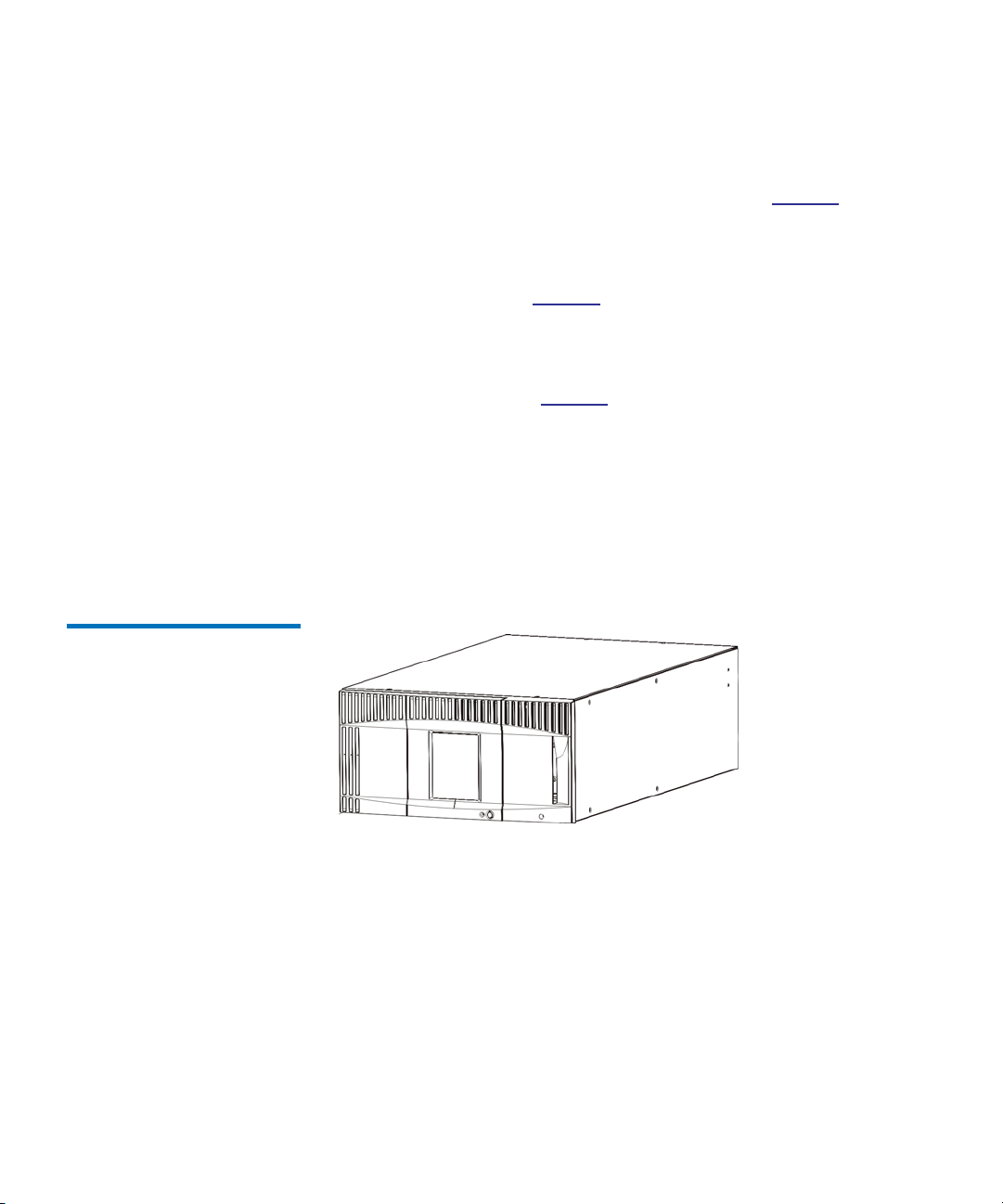
• The ML6010 CM is a 5U Library Control Module. Figure 1 on page 15
shows the front view of the ML6010 CM.
• The ML6020 CM consists of one (1) ML6010 CM 5U Library Control
Module and one (1) PowerVault ML6000 EM 9U Library Expansion
Module (14U total). Figure 2 on page 16 shows the front view of the
ML6020 CM.
• The ML6030 CM consists of one (1) ML6010 CM 5U Library Control
Module and two (2) PowerVault ML6000 EM 9U Library Expansion
Modules (23U total). Figure 3 on page 17 shows the front view of the
ML6030 CM.
In addition, the ML6030 CM configuration can be expanded as follows:
• The ML6030 CM plus one (1) PowerVault ML6000 EM 9U Library
Expansion Module (32U total)
• The ML6030 CM plus two (2) PowerVault ML6000 EM Library 9U
Expansion Modules (41U total)
Figure 1 ML6010 CM Library
Configuration (Standalone 5U
Library Control Module)
Dell PowerVault ML6000 User’s Guide 15
1
Page 16
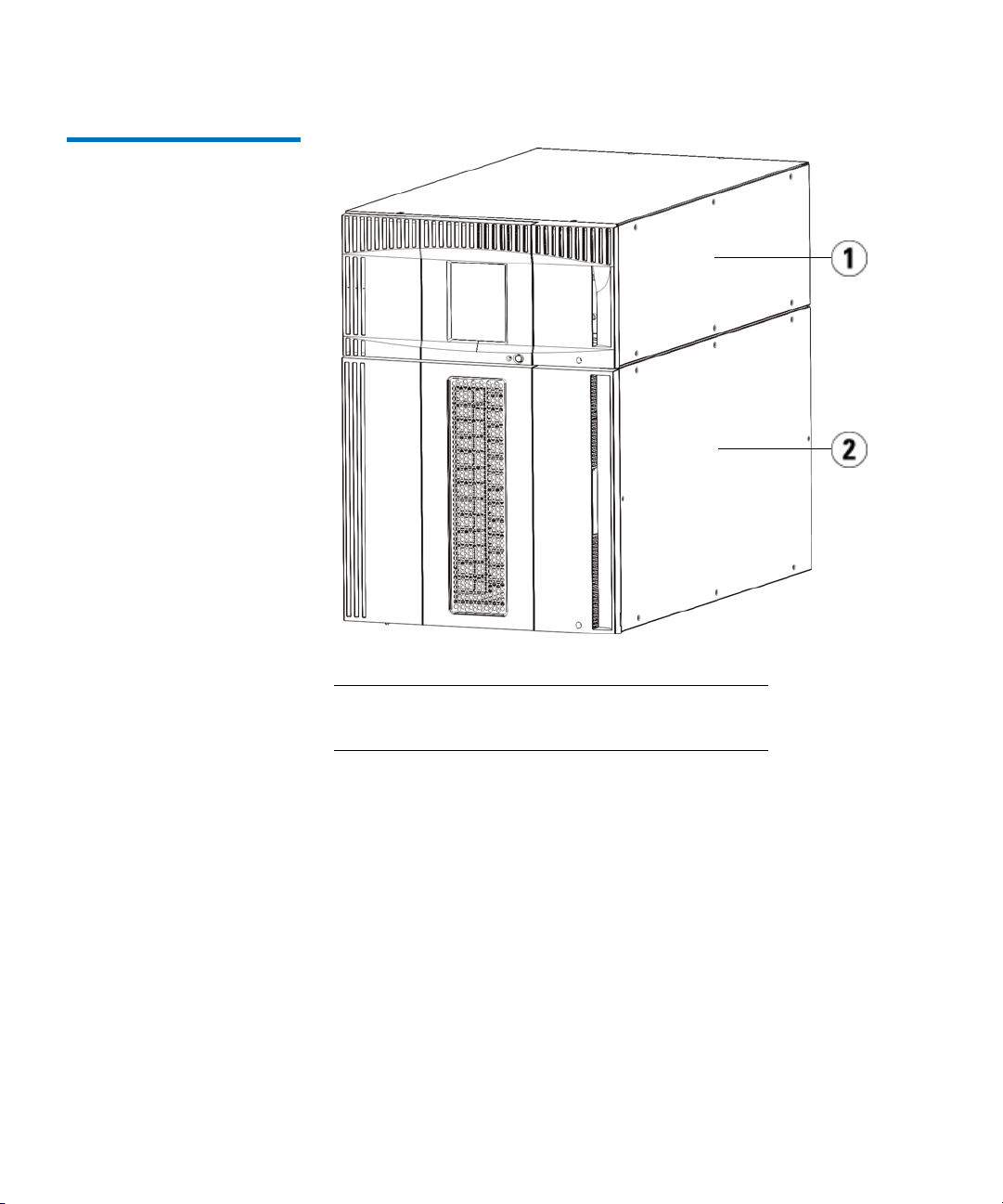
Figure 2 ML6020 CM Library
Configuration (5U Library
Control Module Plus One 9U
Library Expansion Module)
Chapter 3 Description
Library Configuration
1 5U Library Control Module
2 9U Library Expansion Module
Dell PowerVault ML6000 User’s Guide 16
Page 17
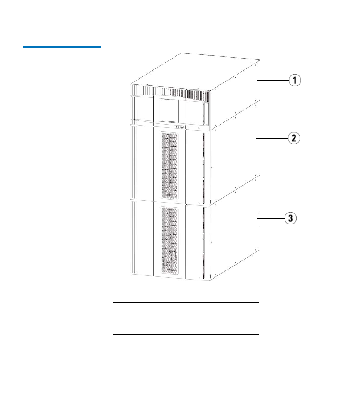
Figure 3 ML6030 CM Library
Configuration (5U
Control Module Plus Two 9U
Library Expansion Modules)
Library
Chapter 3 Description
Library Configuration
1 5U Library Control Module
2 9U Library Expansion Module
3 9U Library Expansion Module
Dell PowerVault ML6000 User’s Guide 17
Page 18

Chapter 3 Description
Modules
Warning: All libraries taller than 14U must be installed in a rack
having a main protective earthing (grounding) terminal,
and power must be supplied via an industrial plug and
socket-outlet and/or an appliance coupler complying with
IEC 60309 (or an equivalent national standard) and having
a protective earth (ground) conductor with a crosssectional area of at least 1.5 mm2 (14 AWG).
To ensure proper airflow and access space, allow 60 cm (24
inches) in the front and back of the library.
Caution: ML6030 (and higher) CM and Expansion Modules require
professional installation. Professional installation may
have been included with your purchase. Please call
1-800-945-3355 to schedule professional installation of
your PowerVault library.
Modules
PowerVault ML6000 libraries are modular, and you can increase the size
at any time. The three base systems for the PowerVault ML6000 library
are as follows:
• ML6010 CM (5U rack height)
• ML6020 CM (14U rack height)
• ML6030 CM (23U rack height)
These configurations can be scaled up by adding PowerVault ML6000
EM 9U Library Expansion Modules to a maximum rack height of 41U. 9U
Library Expansion Modules provide additional capacity as your storage
and tape drive requirements change. See Figure 4 on page 20 for an
illustration of library scalability. For information on installing, removing,
and replacing modules, see Installing, Removing, and Replacing on
page 210.
Dell PowerVault ML6000 User’s Guide 18
Page 19
Chapter 3 Description
Modules
Each module has a specific number of fixed storage slots, I/E station
slots, and tape drive slots available. See Library capacity is as follows. on
page 423 for the number of slots available for each library configurations.
Note: Slot counts in this document do not include five inaccessible
slots in the bottom row of any library configuration. For more
information about these slots, see Unused Slots on page 171.
Caution: ML6030 (and higher) CM and Expansion Modules require
professional installation. Professional installation may
have been included with your purchase. Please call
1-800-945-3355 to schedule professional installation of
your PowerVault library.
5U Library Control Module 3
9U Library Expansion Modules 3
Stackability 3
The 5U Library Control Module is required in any PowerVault ML6000
library configuration. The 5U Library Control Module contains the
robotic controls, library control blade (LCB), and touch screen display.
The 5U Library Control Module also contains an import/export (I/E)
station, fixed storage slots, tape drives, and at least one power supply.
9U Library Expansion Modules are supplementary modules that can be
stacked above or below the 5U Library Control Module. Each 9U Library
Expansion Module contains fixed storage slots, tape drive slots, and
power supply slots.The I/E stations on 9U Library Expansion Modules
are included and may be configured as storage. 9U Library Expansion
Modules also contain bays for optional Fibre Channel (FC) Input/Output
(I/O) blades.
If a 9U Library Expansion Module is used only for storage and does not
contain tape drives or FC I/O blades, it does not need a separate power
supply. All power is derived from the 5U Library Control Module.
The maximum rack height of the library is 41U, which consists of a 5U
Library Control Module and four 9U Library Expansion Modules.
Figure 4 illustrates the stackability of the library.
Dell PowerVault ML6000 User’s Guide 19
Page 20
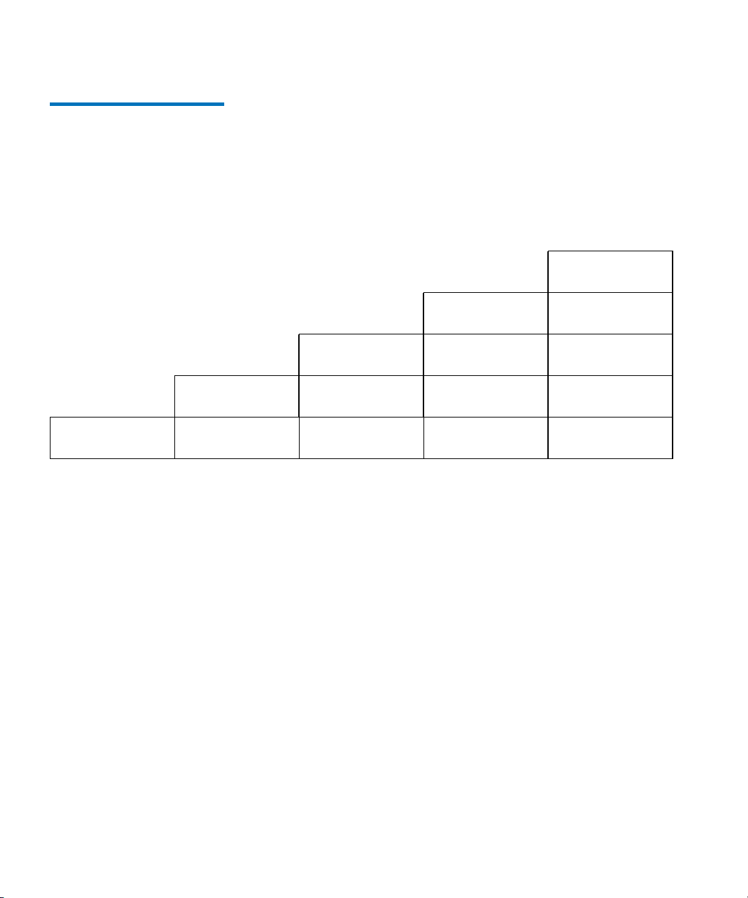
Figure 4 Base Systems Plus
9U Library Expansion Modules
ML6010
(41 slots)
(133 slots)
ML6020
ML6030
(225 slots)
ML6030 CM + 1
9U Library
Expansion
Module
(317 slots)
Chapter 3 Description
Modules
ML6030 CM + 2
9U Library
Expansion
Modules
(409 slots)
9U Library
Expansion Module
5U Library
Control Module
5U Library
Control Module
9U Library
Expansion Module
5U Library
Control Module
9U Library
Expansion Module
9U Library
Expansion Module
5U Library
Control Module
9U Library
Expansion Module
9U Library
Expansion Module
9U Library
Expansion Module
5U Library
Control Module
9U Library
Expansion Module
9U Library
Expansion Module
9U Library
Expansion Module
Dell PowerVault ML6000 User’s Guide 20
Page 21
Front Panel Components
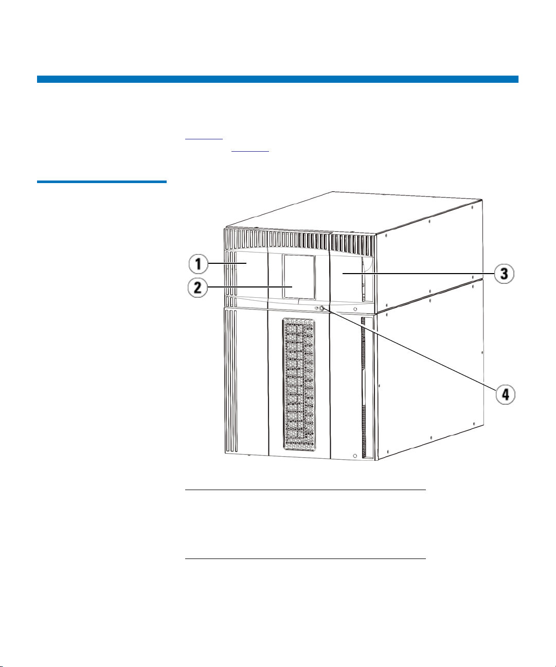
Figure 5 shows the front panel components of the library. The paragraphs
following Figure 5 describe the components in detail.
Figure 5 Front Panel
Components
Chapter 3 Description
Front Panel Components
1 Access door
2 Operator panel
3 I/E station
4 Front power button
Dell PowerVault ML6000 User’s Guide 21
Page 22

Chapter 3 Description
Front Panel Components
Access Door 3
The access door allows access to the internal components of the library.
Each 5U Library Control Module and 9U Library Expansion Module has
an access door. In most cases, you will not need to access the library
through this door except when you want to bulk load or unload
cartridges from the library.
The access door is locked by the I/E station door. To open the access
door, you must first open the I/E station door. If you want to prohibit
access to the library, which is recommended for security reasons, lock the
I/E station door. This keeps unauthorized users from accessing tape
cartridges.
You can lock and unlock the I/E station door using commands on the
Operations menu. If necessary, you can also manually unlock the I/E
station door. For more information, see Locking and Unlocking the I/E
Stations on page 185.
If the access door is opened, the library is not available for use. When an
access door (on any module) is opened, all in-progress motion commands
are stopped, and the picker slowly lowers to the bottom of the library.
When the access door is closed, the library returns any media in the
picker to its original slot and also performs a library inventory.
Caution: Care should be taken to avoid opening the access door
during robotic operations since the robot will stop
immediately and will fail to complete the current
operation.
I/E Station 3
I/E stations enable importing and exporting cartridges with minimal
interruption of normal library operations. I/E stations are located on the
front of the 5U Library Control Module and on the front of 9U Library
Expansion Modules. A 5U I/E station has a capacity of six cartridges. A
9U I/E station has a capacity of 12 cartridges.
The I/E stations can also be configured as storage as well as become part
of a logical division of library resources known as a partition. The I/E
station is shared among all partitions, but the I/E station slots are owned
by one partition at a time. When an I/E station slot is assigned to a
partition, only the assigned partition can access that slot.
Dell PowerVault ML6000 User’s Guide 22
Page 23

Chapter 3 Description
Back Panel Components
Operator Panel 3
Front Power Button 3
The operator panel is the touch screen display device upon which the
graphical user interface (GUI) appears. The operator panel is located on
the access door of the 5U Library Control Module. The library operations
and service functions are performed from this screen. The GUI is also
accessible through a remote Web client. For more information on the
library user interfaces, see
Turning off the front power button turns off the robot and operator panel,
but power still runs to the power supplies. Use the front power button to
manually shut down the library. See Shutting Down, Powering Off, and
Completely Removing Power on page 162 for instructions on how to shut
down or restart the library safely.
Back Panel Components
Figure 6 shows the back panel components of the library. The paragraphs
following Figure 6 describe the components in detail.
Chapter 4, Understanding the User Interface.
Dell PowerVault ML6000 User’s Guide 23
Page 24
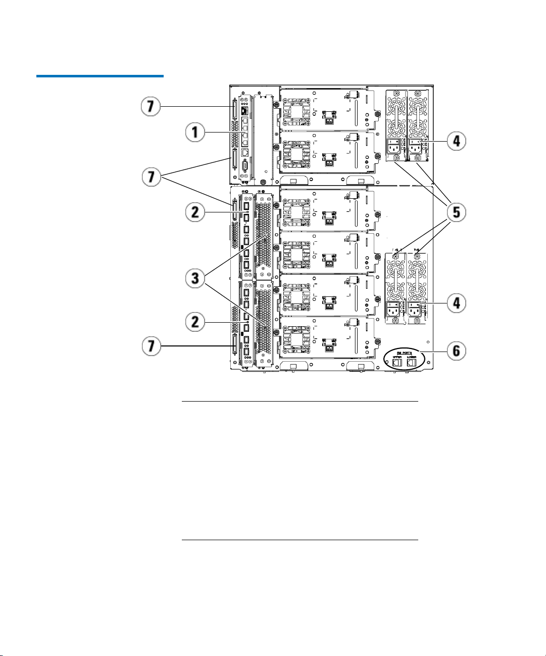
Figure 6 Back Panel
Components
Chapter 3 Description
Back Panel Components
1 Library control blade (LCB)
2 FC I/O blade (optional)
3 FC I/O fan blades (required with FC I/O blades)
4 Rear power switch
5 Power supplies
6 Upper and lower Ethernet ports on 9U Library
Expansion Module
7 Module terminator connectors (CAN bus
connectors)
Dell PowerVault ML6000 User’s Guide 24
Page 25
Chapter 3 Description
Back Panel Components
Rear Power Switches 3
Power System 3
Rear power switches are located on each power supply. Turning off the
rear power switch on a power supply removes all power from the library.
The rear power switches should be used in all emergency and service
situations.
Warning: Turn off the rear power switch whenever you are servicing
the library. In the event of danger to personnel or
property, immediately turn off the rear power switch and
remove all power cords.
Caution: Except in emergencies, use the shutdown procedure
before switching off the rear power switch. See Shutting
Down, Powering Off, and Completely Removing Power
on page 162 for instructions on how to shut down the
library.
The library supports single and redundant power configurations. The
single power configuration has a single AC line input and single DC
power supply. The redundant configuration has dual AC line input and
dual DC power supplies.
If you have redundant power supplies, you can “hot swap” a power
supply (power to the library remains on while you exchange the
hardware), and you can “hot add” power supplies to other modules
(power to the library remains on while you are adding the hardware).
Caution: At least one power supply must be plugged in at all times.
Warning: The power outlet must be available near the library and
must be easily accessible.
Caution: The 9U Library Control Module and each 9U Library
Expansion Module that contains drives must have at least
one power supply for every four drives. You can add a
redundant power supply to each module. Installing one
power supply in one module and another power supply in
another module does not provide redundant power; the
two power supplies must reside in the same module.
Dell PowerVault ML6000 User’s Guide 25
Page 26

Chapter 3 Description
Back Panel Components
The power system consists of the following components:
• Power supply
• AC power cord
The power supply has three light-emitting diodes (LEDs) that provide
status information. These LED status indicators are green and blue in
color.
• Green represents AC OK or DC OK.
• Blue represents swap-mode power status.
Figure 7 shows the power supply LEDs. For more information on the
behavior of the LEDs, see Power Supply LEDs on page 404.
Dell PowerVault ML6000 User’s Guide 26
Page 27
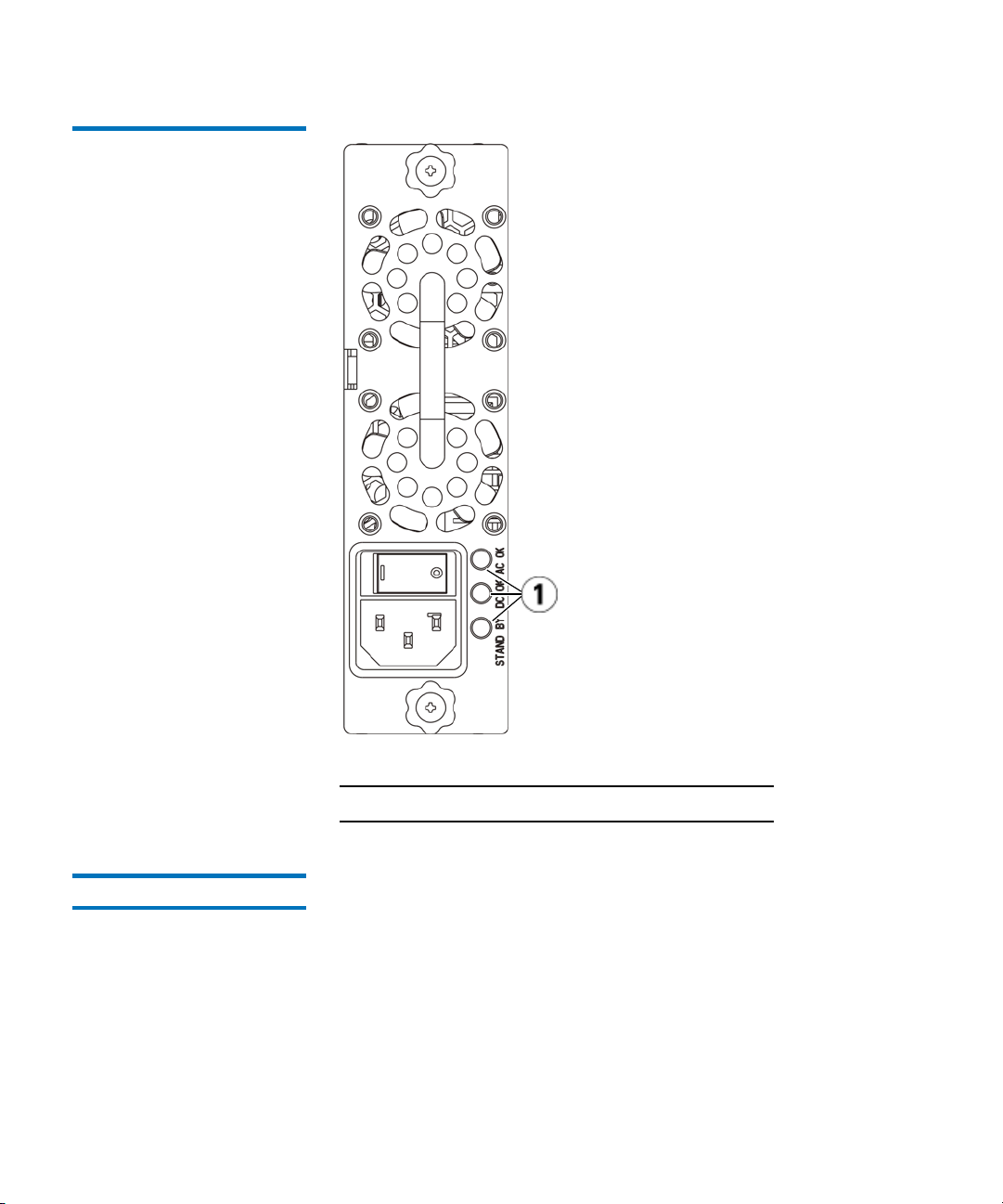
Figure 7 Power Supply LEDs
Chapter 3 Description
Back Panel Components
1 LEDs
Library Control Blade 3
The library control blade (LCB) manages the entire library, including the
operator panel and picker assembly, and is responsible for running
system tests to ensure that the library is functioning properly. The LCB
also provides internal communication to Fibre Channel (FC) I/O blade
slots. The LCB has four Ethernet ports, supporting a total of four FC I/O
blades in the library.
The LCB indicates its status with three LED Reliability, Availability, and
Serviceability (RAS) status indicators. These indicators are green, amber,
and blue in color.
Dell PowerVault ML6000 User’s Guide 27
Page 28

Chapter 3 Description
Back Panel Components
• Green represents processor status.
• Amber represents health status.
• Blue represents power-control status.
Figure 8 shows the location of the LCB components, including LEDs. For
more information on the behavior of the LCB LEDs, see Blade Status
LEDs on page 396.
Dell PowerVault ML6000 User’s Guide 28
Page 29
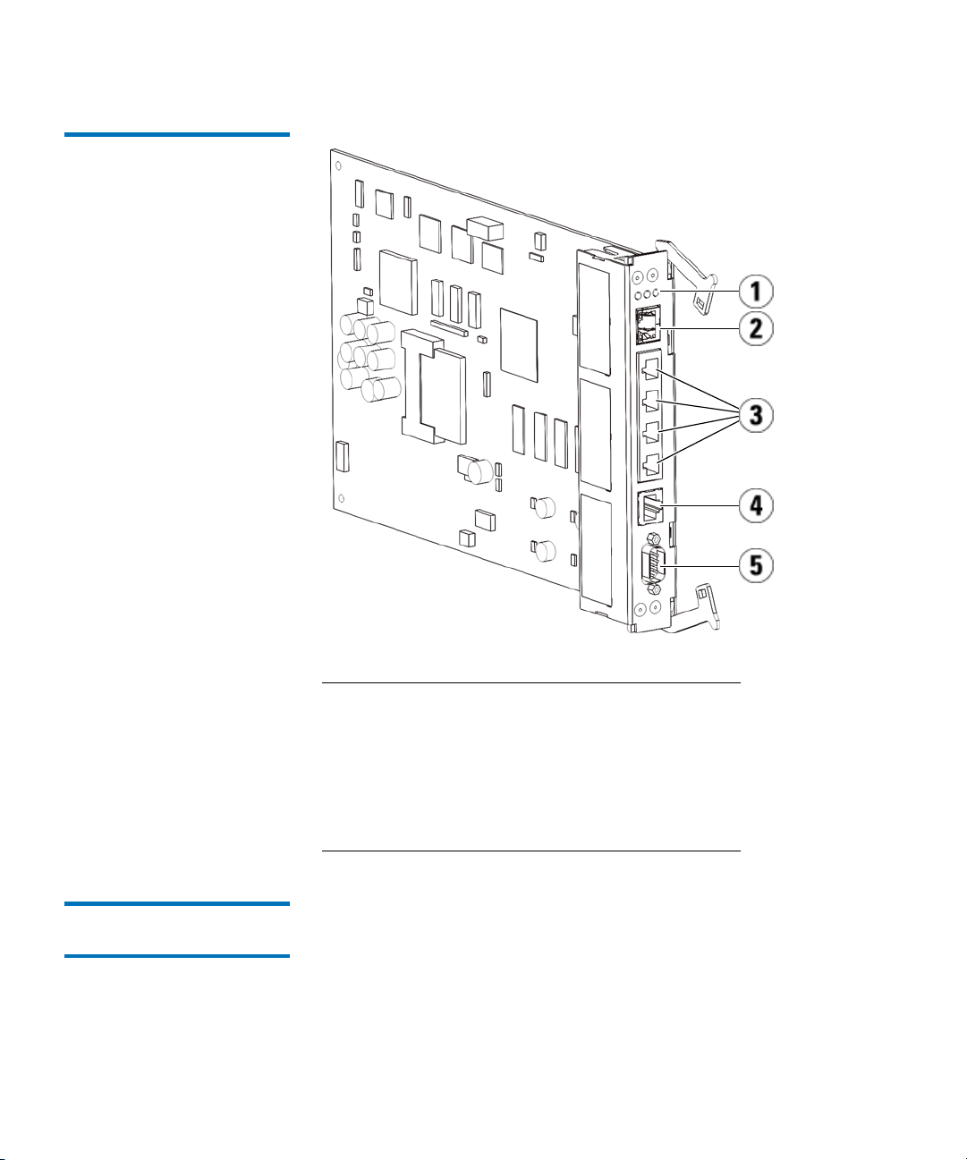
Figure 8 Library Control Blade
Chapter 3 Description
Back Panel Components
1 LEDs (blue, amber, green)
2 Gigabit Ethernet (external network) port
3 Ethernet I/O blade control ports (inactive if FC I/O
blades are not installed)
4 Service Ethernet port
5 Service serial port
Fibre-Channel Input/Output Blades 3
9U Library Expansion Modules support optional Fibre Channel (FC)
Input/Output (I/O) blades that provide connections for FC tape drives in
the library. Each FC I/O blade has an embedded controller that provides
connectivity and features that enhance the performance and reliability of
tape drive operations. I/O blades also aggregate FC tape drive
connections, reducing switch port and cabling requirements.
Dell PowerVault ML6000 User’s Guide 29
Page 30

Chapter 3 Description
Back Panel Components
Each FC I/O blade has six auto-negotiating, 4 Gb/s FC ports and
backplane connections. The FC I/O blade provides two host
communication ports and four connection ports to FC drives. Each FC
I/O blade is cooled by a fan blade that is installed next to the FC I/O
blade in the 9U Library Expansion Module. FC I/O blades and fan blades
are hot-swappable.
FC I/O blades cannot be installed in the 5U Library Control Module, so
your library configuration must include at least one 9U Library
Expansion Module to include FC I/O blades. Each 9U Library Expansion
Module can house up to two FC I/O blades. Depending on the number of
installed 9U Library Expansion Modules, the library can support from
one to four FC I/O blades. No library configuration can contain more
than four FC I/O blades. Any FC drive in the library, including drives in
the 5U Library Control Module, can be connected to an FC I/O blade in a
9U Library Expansion Module.
Note: FC I/O menu commands are available for use only when FC
I/O blades are installed in the library.
The FC I/O blade indicates its status with three LED status indicators.
These indicators are green, amber, and blue in color.
• Green represents processor status.
• Amber represents health status.
• Blue represents power-control status.
Figure 9 shows the FC I/O Blade, including LEDs. For more information
on the behavior of the FC I/O Blade LEDs, see Blade Status LEDs on
page 396.
For information on configuring I/O blades, see Working With FC I/O
Blades on page 109.
For information on installing and cabling FC I/O blades and FC tape
drives, see Chapter 12, Installing, Removing, and Replacing.
Dell PowerVault ML6000 User’s Guide 30
Page 31

Figure 9 FC I/O Blade
Chapter 3 Description
Back Panel Components
1 FC ports to host(s)
2 FC ports to drive(s)
3 LEDs (blue, amber, green)
Each FC I/O blade is cooled by a fan blade that is installed next to the FC
I/O blade in the 9U Library Expansion Module. For information on
installing the fan blade, see Adding, Removing, and Replacing the FC
I/O Fan Blade on page 370.
Figure 10 shows the FC I/O fan blade, including the LED. The single
amber LED represents health status. For more information on the
behavior of the FC I/O fan blade LED, see Tape Drive LEDs on page 400.
Dell PowerVault ML6000 User’s Guide 31
Page 32

Figure 10 FC I/O Fan Blade
Chapter 3 Description
Robotic System and Barcode Scanner
1 LED (amber)
Robotic System and Barcode Scanner
The robotic system identifies and moves the cartridges between the
storage slots, tape drives, and the I/E station. The robotic arm (picker)
has picker fingers that enable it to grab tape cartridges and move them
into positions along X, Y, and Z motion coordinates. The robotic system
and the barcode scanner work together to identify the locations of
resources within the library.
Dell PowerVault ML6000 User’s Guide 32
Page 33

Each tape cartridge must contain a barcode that the barcode scanner
reads during the inventory process. During the inventory process, the
barcode scanner reads the fiducial labels to identify the types of
magazines and tape drives that are installed in the library.
Every tape cartridge must have a unique machine-readable barcode
attached to it. Tape cartridges cannot have duplicate barcode labels. This
barcode identifies the cartridge. The library stores the physical location of
the tape cartridge in an inventory database. All library or host requests
typically reference the location of the tape cartridges based on this
barcode number. Barcode labels are mandatory and must adhere to
specific standards. For more information on barcodes, see Chapter 14,
Working With Cartridges and Barcodes.
Tape Drive Support
Details about tape drive support include:
Chapter 3 Description
Tape Drive Support
• Every library configuration must contain at least one tape drive.
• 5U Library Control Modules can hold a maximum of two tape drives.
• 9U Library Expansion Modules can hold a maximum of four tape
drives.
Please see Supported Components on page 421 for a list of tape drives
and media supported by the PowerVault ML6000 library.
The library supports mixing different tape drive types within the library
and within partitions. For information on how to do this, see Working
With Partitions on page 71.
SCSI and SAS tape drives are attached directly to the host. FC tape drives
can be directly attached to hosts or to the Storage Area Network (SAN).
FC tape drives can also be attached to FC I/O blades, which manage
communication between the hosts and the drives. For more information
on FC I/O blades, see Working With FC I/O Blades on page 109.
Tape drives are installed into tape drive slots in the rear of the library. If a
tape drive slot is empty, a filler plate covers the empty tape drive slots to
prevent debris from entering the library. Tape drives are shipped filling
Dell PowerVault ML6000 User’s Guide 33
Page 34

Library Features
Chapter 3 Description
Library Features
the tape drive slots from the bottom to the top of the library, but the tape
drives can be reinstalled in any available tape drive slot.
Note: Tape drive filler plates must be in place for the library to
operate at normal speed.
For information on adding tape drives, see Adding a Tape Drive on
page 354.
This section describes several features of PowerVault ML6000 libraries.
User Interface 3
Partitions 3
The operator panel is located on the front door of the 5U Library Control
Module and allows you to work locally on the library via the user
interface. The Web client allows you to view and perform library
functions from remote sites and is accessible through a browser. The
operator panel and Web client contain a similar user interface and
functionality.
See Chapter 4, Understanding the User Interface for more information
about the operator panel and the Web client.
Partitions are virtual sections within a library that present the appearance
of multiple, separate libraries for purposes of file management, access by
multiple users, or dedication to one or more host applications.
Organizing the library into partitions divides the resources into virtual
sections. Partitions can be used to control access to portions of the library
by granting permissions to user accounts to access certain partitions.
For more information on partitions, see Working With Partitions on
page 71.
Dell PowerVault ML6000 User’s Guide 34
Page 35

Chapter 3 Description
Licensable Features
Control Path Modification3
Support for WORM 3
The control path tape drive is used to connect a partition to a host
application. Only one tape drive can be selected as the control path at one
time. For more information, see Working With Control Paths on page 86.
PowerVault ML6000 tape libraries support WORM (write once, read
many) technology in LTO-3, LTO-4, LTO-5 and LTO-6 tape drives.
WORM allows non-rewriteable and non-erasable data to be written and
provides extra data security by prohibiting accidental data erasure. The
WORM feature is supported whenever you use WORM cartridges.
Licensable Features
In addition to the standard features, the following additional, licensable
features are available for the PowerVault ML6000:
• Advanced Reporting, described in Chapter 6, Advanced Reporting
• Capacity on Demand, described in Chapter 7, Capacity on Demand
• Library Managed Encryption, described in Chapter 8, Library
Managed Encryption
If you purchase these features with your library, the license will be
installed when you receive the library. If you upgrade or add new
features after the initial purchase, you will need to obtain and install a
license key. For information on how to obtain and install a license key, see
Obtaining and Installing a License Key on page 88.
Understanding the Location Coordinates
This section describes the numbering system the library uses to identify
components of the library. The library location coordinates contain the
following digits: [Module],[Column],[Slot]. Figure 11 shows how a
Dell PowerVault ML6000 User’s Guide 35
Page 36

Figure 11 Library Location
Coordinates
Chapter 3 Description
Understanding the Location Coordinates
library with a 5U Library Control Module and a 9U Library Expansion
Module is numbered.
Note: The library location coordinates are different from the logical
element addressing; see Understanding Logical Element
Addressing on page 38 for more information.)
Dell PowerVault ML6000 User’s Guide 36
Page 37

Chapter 3 Description
Understanding the Location Coordinates
Modules 3
Columns 3
Library modules are represented by the first digit of a library coordinate.
Modules are identified relative to the 5U Library Control Module.
The 5U Library Control Module is numbered 0 (zero). 9U Library
Expansion Modules stacked above the 5U Library Control Module are
addressed with positive integer digits depending on their position above
the 5U Library Control Module. For example, the 9U Library Expansion
Module stacked directly above the 5U Library Control Module is number
1. The 9U Library Expansion Module stacked directly above module 1 is
number 2, and so on.
Modules stacked below the 5U Library Control Module are numbered
with negative integer digits, also depending on their relative position to
the 5U Library Control Module. For example, the 9U Library Expansion
Module stacked directly below the 5U Library Control Module is number
–1. The 9U Library Expansion Module stacked directly below module –1
is number –2, and so on.
A storage column is a group of slots arranged vertically in the library.
Columns are represented by the second digit of a library coordinate.
Columns are identified relative to the front left of the library. The column
in the front left of the library is number 1. The column numbering
continues around the library in a clockwise direction. The I/E station
column is always number 6.
Slots 3
Fixed storage slots are represented by the third digit of the library
location coordinate. Within each column, slots are numbered from top to
bottom, starting at 1. For example, in Figure 11 on page 36, the full
location coordinate of Slot 1 is 0, 1, 1.
Tape Drives 3
Tape drives are addressed first by module and then by tape drive bay
within the module. The drive bays within a module are numbered from
top to bottom. A one-based numbering system is used. The full address of
a tape drive is in the form of [module,drive bay]; for example: [0,1], [1,3],
[-1,2].
Dell PowerVault ML6000 User’s Guide 37
Page 38

Chapter 3 Description
Understanding Logical Element Addressing
Fibre Channel I/O Blades 3
Power Supplies 3
Fibre Channel (FC) I/O blades are addressed first by module and then by
FC I/O blade bay within the 9U Library Expansion Module. The blade
bays within a module are numbered from top to bottom. A one-based
numbering system is used. The full address of a an FC I/O blade bay is in
the form of [module,FC I/O blade bay]; for example: [1,1], [-1,2].
Power supplies are addressed as [module,PS#], where PS# is 1 for the left
power supply and 2 for the right power supply. The PS# is also etched on
the module chassis, above each power supply.
Understanding Logical Element Addressing
The library uses standard industry conventions to logically number every
storage slot, I/E station slot, and tape drive in the library. Host software
is designed to understand this addressing system, and generally there are
no problems relating to tape cartridge slots. However, hosts sometimes
have problems relating to tape drives, particularly when tape drives, 5U
Library Control Modules, or 9U Library Expansion Modules are added or
removed, or empty tape drive slots exist. This section explains how the
library logically addresses tape drives and slots, so that you can avoid
common problems with host software.
Note: The logical element addressing described in this section is
different from the library-specific location coordinates
described in Understanding the Location Coordinates on
page 35.)
Tape Drive Logical Element Addressing 3
Dell PowerVault ML6000 User’s Guide 38
Tape drive logical element addresses are assigned by partition. The
numbering is sequential within a partition and starts over with each
partition. The addresses start with the lowest library module in a
partition. The top tape drive in the module and partition is always
number 256. The tape drive beneath that is 257, and so on until all tape
drives in that module/partition have been accounted for. Numbering
continues with the top tape drive in the next module up. Empty tape
drive slots are skipped (they are not given an element address).
Page 39

Chapter 3 Description
Understanding Logical Element Addressing
Host software may have problems recognizing tape drives when tape
drives, 5U Library Control Modules, or 9U Library Expansion Modules
are added, removed, or replaced; or when partitions are added, deleted,
or modified, because existing logical element addresses can change.
Therefore, after making any of these types of modifications, you must
refresh the configuration of any backup application that manages the
library to reflect new tape drive positions. In addition, you may need to
reboot the host server(s) or rescan the bus to detect the changes.
See Figure 12 on page 41 for a simple example of element addressing in a
14U library with a single partition, six tape drives installed and no empty
tape drive slots. Note that multiple partition can create complexity. If you
need help with the element addressing in your library, contact Dell
Technical Support (see Appendix C, Contacting Dell).
Cartridge Slot Logical Element Addressing 3
Tape cartridge slots are assigned logical element addresses by partition.
The numbering is sequential within a partition and starts over with each
partition. Numbering begins at the top left slot (as you look at the library
from the front) in the lowest module in the library and moves
sequentially down the left-most column. The top left slot of every
partition is always number 4096, the slot beneath that is 4097, and so on.
When the numbering reaches the bottom of the column, it continues to
the top slot in the next column to the right (as long as it is in the same
module and partition) and moves down that column. When all of the
slots in the lowest module belonging to a partition have been accounted
for, numbering continues to the top left slot in the next module above (as
long as it is in the same partition). The numbering can get tricky when
partitions span modules and do not use all of the slots in a module.
Tape cartridge slots are assigned a logical element address whether they
contain a cartridge or not. Cartridges themselves are not given a logical
element address; only the slot is. Slot element addresses change when
slots are added or removed; partitions are added, removed, or modified;
or cleaning slots are added or removed.
I/E station slots are numbered differently from partitions. Numbering
begins at the top I/E station slot in the uppermost module that contains
I/E station slots, and continues sequentially downward. This top slot has
element address 16. The slot beneath that is 17, and so on.
Cleaning slots belong to the System partition and are not reported to the
host. Cleaning slots are skipped (they are not given a logical element
address), so adding or removing a cleaning slot will renumber all of the
slots in a partition.
Dell PowerVault ML6000 User’s Guide 39
Page 40

Chapter 3 Description
Understanding Logical Element Addressing
Generally, host software easily recognizes logical slot element addresses,
even when they change. The next time the host issues a READ ELEMENT
STATUS command, it will process the new number and recalculate all of
the slot addresses.
See Figure 12 on page 41 for a simple example of element addressing in a
14U library with a single partition.
Dell PowerVault ML6000 User’s Guide 40
Page 41

Figure 12 Logical Element
Addressing, 14U, One Partition,
Six Tape Drives Installed
Chapter 3 Description
Understanding Logical Element Addressing
Note: Empty drive bay
element addresses are
skipped. This picture
assumes six tape drives are
installed.
Tape cartridge slots in partition
I/E station slots
Tape drives
Unused slots
Dell PowerVault ML6000 User’s Guide 41
Page 42

Chapter 4
4Understanding the User Interface
The user interface of PowerVault ML6000 libraries is available in two
formats: the operator panel and the Web client. Operations on the library
can be performed locally on the 5U Library Control Module using the
operator panel or remotely on your computer using the Web client.
Similar functionality with common elements is used for both formats.
Both the Web client and operator panel user interfaces are required to
operate the library. Some functionality is only available through the Web
client, and some functionality is only available through the operator
panel. However, using the Web client rather than the operator panel to
perform library operations (when possible) is recommended.
Caution: Do not perform inventory operations (for example,
working with RAS tickets, creating/modifying/deleting
partitions) while the library is performing an inventory.
Doing so may result in inventory discrepancies, such as
missing tape cartridges.
Dell PowerVault ML6000 User’s Guide 42
Page 43

Common User Interface Elements
The user interface consists of the following areas:
• Header — appears on every screen and contains the company logo,
product name, and the three main navigation buttons. The main
navigation buttons are:
• Home — Home page.
• Help — Context-sensitive Help for the active screen.
• Logout — Ability to log out.
• Title Bar/Menu Tabs (operator panel)— This area appears below the
header. On the home page, it provides the library/partition name
and access to the menu tabs on the main screen. On all other screens,
this area is a single bar and provides the screen name.
• Menu Bar (Web client)— Lists the menu choices.
• Main — Main content area of the screen.
Chapter 4 Understanding the User Interface
Common User Interface Elements
• Health/Navigation — provides information about the “health” of the
library by means of three subsystem status buttons: Library, Drives,
and Media. See System Summary and Subsystem Status on page 45
for more information on the subsystem buttons.
Note: A message in the header alerts you when the robot is not ready
to perform library functions. See Troubleshooting “Library
Not Ready” Messages on page 386 for more information on
“Library Not Ready” messages displayed in the header.
Figure 13 and Figure 14 show the operator panel and the Web client
interfaces.
Dell PowerVault ML6000 User’s Guide 43
Page 44

Figure 13 Operator Panel User
Interface
Chapter 4 Understanding the User Interface
Common User Interface Elements
Dell PowerVault ML6000 User’s Guide 44
Page 45

Figure 14 Web Client User
Interface
Chapter 4 Understanding the User Interface
Common User Interface Elements
System Summary and Subsystem Status 4
You can quickly gauge the health of the library by observing the color of
the three subsystem status buttons located at the bottom of the home
page. These buttons provide quick access to information about the
“health” of the library for faster recovery if problems occur. You can
select the buttons to view Reliability, Availability, and Serviceability
(RAS) tickets that report problems in the subsystems.
The three subsystems are:
• Library — This subsystem represents connectivity, control, cooling,
power, and robotics.
• Drives — This subsystem represents tape drive components, such as
tape drives, tape drive firmware, and tape drive sleds.
• Media — This subsystem represents media components, such as
cartridges and barcode labels.
Dell PowerVault ML6000 User’s Guide 45
Page 46

Chapter 4 Understanding the User Interface
Common User Interface Elements
Each subsystem button will be in one of three states indicated by color.
The three states are:
• Green — No RAS tickets exist for this subsystem, or, if any tickets do
exist, they have all been closed.
• Yellow — The library contains open or unopened, low-severity
(Severity 3) or high-severity (Severity 2) RAS tickets for this
subsystem.
• Red — The library contains open or unopened urgent (Severity 1)
RAS tickets for this subsystem.
If the color of a subsystem button is red or yellow, you can click the
button to display the corresponding RAS Tickets screen. This screen lists
library, drives, or media RAS tickets, depending on which button was
selected. RAS tickets display in order of last occurrence of each event,
starting with the most recent.
Note: Last Occurrence indicates the last time a ticket event occurred.
This information updates any time the event recurs. Last
Occurrence
does NOT update if you open, close, or resolve the
RAS Ticket.
You can change the order in which the RAS tickets are displayed by
clicking any header item (for example, Severity, Last Occurrence, or
Name).
On the Web client, you can view closed tickets by selecting the Include
Closed Tickets
check box.
You can also open the All RAS Tickets screen by selecting Tools > All RAS
Tickets
. See About RAS Tickets on page 377 for more information about
RAS tickets.
Home Page 4
The home page is common to both the operator panel and the Web client.
The home pageprovides tabular data on the capacity of the library’s
partitions, slots, and drives. You can use the home page to see a quick
summary of the capacity of the library. You can also see which partitions
are online (in the Storage Slots section). The current user’s login
privileges determine the information that is displayed on the home page.
Dell PowerVault ML6000 User’s Guide 46
Page 47

Operator Panel
Chapter 4 Understanding the User Interface
Operator Panel
Details about the home page include:
• On the Web client, users see the partitions (in alphabetical order) to
which they have access.
• On the operator panel, if users have access to more than one partition,
they can navigate to other partitions using the arrows next to the
partition name in the title bar at the top of the screen.
For more information about user privileges, see User Privileges on
page 54 and Working With User Accounts on page 96.
The operator panel is physically attached to the front door of the 5U
Library Control Module. The user interface appears on the touch-screen
LCD display of the operator panel for executing basic library
management functions. Audible feedback, or “key click” sounds, are
generated when a user presses a button on the operator panel. Users can
choose to disable the audible feedback. See Configuring System Settings
on page 126.
Operator Panel Keypads 4
Operator Panel Indicates Intervention Required 4
Dell PowerVault ML6000 User’s Guide 47
When a user touches a text box requiring data entry, a keypad screen
appears. The alpha, numeric, or month keypad appears, depending on
the type of input field touched. All alphabetic character entries are lower
case. The text box appears at the top of screen, and the
numbers/characters appear as they are entered. Pressing 123 opens the
numeric keypad.
The operator panel lights up (screen saver turns off) if intervention is
required. For example, when manual cartridge assignment is enabled, the
operator panel lights up following an import of tapes into the I/E station
so that the operator sees the prompt to assign tapes to a partition.
Page 48

Web Client
Chapter 4 Understanding the User Interface
Web Client
The Web client user interface is similar to the operator panel user
interface. The Web client interface is accessible from supported Web
browsers. See Library Capacity on page 423 for information about
supported browsers.
To manage the library from a remote location, you must set up the
library’s initial network configuration from the operator panel touch
screen. See Configuring Library Security Settings on page 124 for
information on setting the network configuration settings for remote use.
You must disable Web browser popup blockers to use the Web client
interface and the library’s online Help. Add the PowerVault ML6000’s
Internet Protocol (IP) address to the list of trusted/allowed sites on your
PowerVault ML6000-supported browser, so the Web client pages will
automatically refresh.
Note: Do not use your Internet browser Back button to navigate the
Web client pages. Instead, use the buttons provided within the
Web client.
Note: Log out of the library before closing the Internet browser
window when you are using the Web client. If you do not log
out, the session will remain open.
Menu Trees
The following menus organize operations and commands into logical
groupings:
• The Setup menu consists of commands that administrators can use to
set up and configure various aspects of the library, including
partitions, I/E station slots, cleaning slots, control paths, network
settings, drive settings, users, notifications, date and time, licenses,
FC I/O blades, and e-mail.
Dell PowerVault ML6000 User’s Guide 48
Page 49

Chapter 4 Understanding the User Interface
Menu Trees
• The Operations menu consists of commands that enable users to
change the library’s mode of operations, import and export
cartridges, load and unload tape drives, move media, perform
diagnostics, and log off. Administrators can also access commands to
lock or unlock the I/E station and to shut the library down.
• The Tools menu consists of commands that you can use to maintain
your library, such as viewing RAS Tickets, generating diagnostic
logs, identifying drives, configuring the internal network, saving and
restoring the library configuration, setting system and security
settings, and updating firmware.
• The Reports menu (Web client only) consists of summaries of library
information.
The menus vary somewhat between the Web client and operator panel
user interfaces. Administrators have access to all menu commands; users
with user privileges have more limited access.
Table 1 lists the Web client menus. Some menu commands are available
only to administrators.
I/O blade menu items are available for libraries that contain I/O blades.
Dell PowerVault ML6000 User’s Guide 49
Page 50

Table 1 Web Client Menus
Chapter 4 Understanding the User Interface
Menu Trees
Setup Menu
• Setup Wizard
• Partitions
• Cleaning Slots
• I/E Station Slots
• Drive Settings
• Control Path
• License
• Notifications
• E-mail Configuration
• Advanced Reporting
(if licensed)
• Receiver
• Media Security
• RAS
• Receiver
• Contact
• Network Management
• Network
• SNMP
• SNMP Trap
Registrations
*
Addresses
Addresses
Information
Operations Menu Tools Menu
• Media
•Move
• Import
• Export
• Cleaning Media
• Import
• Export
• Partitions
• Change Mode
• Drive
• Load
• Unload
• Change Mode
• I/E Station
Lock/Unlock*
• System Shutdown*
• Logout
• All RAS Tickets
• Capture Snapshot
• Save/Restore
Configuration
• E-mail
Configuration
Record
• Save Configuration
Record
• Identify Drives
• Drive Operations
• Download SNMP
MIB
• FC I/O Blade Info**
• FC I/O Blade Port
Info**
• Update Library
Firmware
• Reset Factory
Defaults
• Diagnostics
*
Reports Menu
• System Information
• Library Configuration
• Network Settings
• Logged In Users*
• All Slots
• Log Viewer*
• Advanced Reporting*
• Drive Resource
Utilization
• Media Integrity
Analysis
• About
Dell PowerVault ML6000 User’s Guide 50
Page 51

Chapter 4 Understanding the User Interface
Menu Trees
Setup Menu
• User Management
• User Accounts
• Remote
Authentication
• FC I/O Blades**
• Port Configuration
• Channel Zoning
• Host Mapping
• Host Management
• Host Port Failover
• Data Path
Conditioning
• FC I/O Blade Control
• Encryption (if licensed)
• System Configuration
• Partition
Configuration
• System Settings
• Date & Time
*
Operations Menu Tools Menu
*
Reports Menu
*
Administrators only. **Available only when the library contains I/O blades.
Table 2 lists the operator panel menus. Some menu commands are
available only to administrators. I/O blade menu items are available for
libraries that contain I/O blades.
Dell PowerVault ML6000 User’s Guide 51
Page 52

Table 2 Operator Panel
Menus
Chapter 4 Understanding the User Interface
Menu Trees
Setup Menu
a
• Partition Mgmt
• Create Partition
• Delete Partition
• Configure I/E Station Slots
• Configure Cleaning Slots
• User Mgmt
• Create User
• Modify User
• Drive Settings
• Fibre
• SCSI
• SAS
• Notification
• E-mail Alerts
• E-mail Account
• Customer Contact
• Licenses
• Date & Time
• Network Mgmt
• IP version 4
• IP version 6 (if enabled)
• Port Settings
• Control Path
Operations Menu Tools Menu
• Move Media
• Import Media
• Export Media
• Import Cleaning Media
• Export Cleaning Media
• Change Partition Mode
• Load Drive
• Unload Drive
• Change Drive Mode
• Lock/Unlock I/E Station
• Shutdown
a
• All RAS Tickets
• Capture Snapshot
• Drive Mgmt
• Create a fir mware tape
• Update drive firmware from tape
• Erase a firmware tape
• Clean drive
• Reset drives
• Drive Info
a
• About Library
• Network Info
• View Drive Info
• Partition Info
• Internal Network
• System Settings
• User Session Timeout (minutes)
• Touch Screen Audio
• Unload Assist
• Logical SN Addressing
• Manual Cartridge Assignment
• Disable Remote Service User
• Enable SSL
• Enable SNMP V1/V2
• Enable IPv6
• Enable SMI-S
• Unlabeled Media Detection
a
a
a
a
a
a
a
a
a
Dell PowerVault ML6000 User’s Guide 52
Page 53

Chapter 4 Understanding the User Interface
Menu Trees
Setup Menu
• FC I/O Blades
a
b
• Port Configuration
• Channel Zoning
• Host Mapping
c
• Host Management
• Host Port Failover
• Data Path Conditioning
• FC I/O Blade Control
Operations Menu Tools Menu
Security
c
Display Settings
• Library Tests
• Blade Info
• Command History Log
• Factory Defaults
a
• Network Interface
• SSH Services
• ICMP
• Remote UI
• SNMP
• SMI-S
• Brightness
• Contrast
• Defaults
a
• Installation & Verification Tests
• Library Demo
• View Last Summary Log
• View Last Detailed Log
• E-mail Last Detailed Log
b
• Port Info
ab
a
a
Administrators only. bAvailable only when the library contains I/O blades. cVisible only when host mapping has
been enabled.
Dell PowerVault ML6000 User’s Guide 53
Page 54

User Privileges
Chapter 4 Understanding the User Interface
User Privileges
User privilege levels are manually assigned to user accounts created
within the library. Controlling access to screens and operations within the
library preserves the integrity of the library and the data that is stored in
it. See Working With User Accounts on page 96 for more information on
setting user privilege levels.
Two types of users are defined in PowerVault ML6000 libraries:
• Administrators have access to the entire physical library and all of its
partitions, and can configure the library and set up user and
administrator accounts. The library ships with a default
administrator account. The user name for the default administrator
account is admin and the password is password. You cannot modify
or delete the user name for the default administrator account, but you
can modify the password. If you misplace the password for the
default administrator account, contact Dell Technical Support (see
Appendix C, Contacting Dell).
• Users have access to one or more assigned partitions, as well as
portions of the Operations and Reports menus. Users cannot access
the Setup and Tools menus. Users can perform functions within a
partition (such as performing cartridge and tape drive operations),
but cannot set up or configure the library (for example, creating or
deleting partitions).
Details on user privileges include:
• The library can contain eighteen user accounts (user or administrator
or both), including the default administrator account.
• Eighteen user (user or administrator or both) sessions can be active at
one time.
• The same user can be logged in to a library from multiple remote
locations.
• Clicking the close button (X) in the upper-right corner of the Web
client closes the browser window but does not log the user or
administrator out.
Dell PowerVault ML6000 User’s Guide 54
Page 55

User Access
Chapter 4 Understanding the User Interface
User Access
• All users are logged out automatically after a configurable period of
inactivity. The default user session timeout period is 30 minutes, but
administrators can change the user session timeout to a value from 15
minutes to 480 minutes (eight hours). See Configuring System
Settings on page 126.
• A screen saver is invoked after 10 minutes of inactivity on the
operator panel. After an hour of inactivity, the screen will appear
black. If the user has not been logged out for inactivity, touching the
operator panel will reactivate it, returning the user to the screen last
in use. (The Web client does not use a screen saver.)
• An administrator can disable any access to the library from the Web
client. For more information, see Configuring System Settings on
page 126.
Administrators have access to the entire library. Users with user
privileges can only access some of the menus. See Table 1 on page 50 for
the Web client menu tree and privilege level information. See Table 2 on
page 52 for the operator panel menu tree and privilege level information.
Dell PowerVault ML6000 User’s Guide 55
Page 56

Chapter 5
5Configuring Your Library
Once you have installed the hardware as described in Chapter 2, Setting
Up the PowerVault ML6000 Library, you are ready to configure your
library’s settings. A Setup Wizard helps you get started configuring your
library, and menu commands on both the operator panel and the Web
client allow you to reconfigure your library at any time.
Caution: Always save the library configuration after modifying
configurable items. This will allow you to restore the most
current settings if necessary. See Saving and Restoring the
Library Configuration on page 384.
About the Setup Wizard
When you first power on the library, the operator panel displays the
Setup Wizard, which walks you through the initial configuration of the
library’s basic operational settings.
The Setup Wizard on the operator panel only runs once, at initial startup.
After that, administrators access the Setup Wizard any time via the Web
client or use commands on the Setup and Operations menus to modify all
library settings, including network settings. See Completing the Library
Configuration With Menu Commands on page 57.
Dell PowerVault ML6000 User’s Guide 56
Page 57

Chapter 5 Configuring Your Library
About the Setup Wizard
While completing the Setup Wizard at initial startup is recommended,
you may need to begin using the library locally immediately. In this case,
you can cancel out of the Setup Wizard and allow the library to run on the
default configuration settings. See Default Configuration Settings on
page 60.
For additional information, see Using the Setup Wizard on page 58.
Using the Default Administrator Account 5
Completing the Library Configuration With Menu Commands 5
When you power on the library for the first time, you do not need to log
in to use the operator panel. You can start using the Setup Wizard
immediately. After the initial setup session on the operator panel,
however, you will need to log in to the operator panel as well as the Web
client.
The library ships with a default administrator account. The user name on
the account is admin and the password is password. When you see the
Login screen on the operator panel or Web client, type admin in the User
Name
text box and password in the Password text box. As soon as the
initial setup is complete, you should change the password on the default
administrator account. For information on changing passwords, see
Modifying Local User Accounts on page 98.
Note: You cannot delete the default administrator account or modify
the user name. You can, however, change the password.
Note: If you misplace the password for the default administrator
account, contact Dell Technical Support (see Appendix C,
Contacting Dell).
The Setup Wizard is an aid to assist you with the initial configuration of
the library. The Setup Wizard, however, contains only a subset of
configuration tasks. The operator panel tabs and Web client menus
provide access to all configuration options that are included in the Setup
Wizard and many that are not. Once the initial Setup Wizard session is
complete, administrators can choose whichever method is most
convenient or necessary for modifying library settings.
The following topics cover using the Setup Wizard as well as Setup and
Operations commands to configure the library. Paths to open the
appropriate screens on both the operator panel and the Web client are
Dell PowerVault ML6000 User’s Guide 57
Page 58

given for each task. For the operator panel, the paths refer to the
navigation tabs at the top of the home page. For the Web client, the paths
refer to the menus.
For the menu trees on both the operator panel and Web client, see Menu
Trees on page 48.
Note: Power cycling (powering the library on and off) is not
Using the Setup Wizard
The Setup Wizard simplifies the process of configuring the library. When
you first power on the library, the operator panel displays the Setup
Wizard. After that, you can no longer access the Setup Wizard from the
operator panel. You can always access the Setup Wizard from the Setup
menu on the Web client.
Chapter 5 Configuring Your Library
Using the Setup Wizard
necessary to configure the library.
The recommended procedure for using the Setup Wizard for the initial
configuration is as follows:
1 Turn on the library and begin using the Setup Wizard on the operator
panel.
2 Work through all of the screens as prompted (see Setup Wizard Tasks
on page 60).
3 When you get to the network configuration screens, configure the
network settings as follows:
Note: You cannot log into the Web client until you have
configured the network settings.
Dell PowerVault ML6000 User’s Guide 58
Page 59

Chapter 5 Configuring Your Library
Using the Setup Wizard
• If you are using IPv4: On the Setup Wizard: Enable IPv6 screen, do
NOT select the Enable IPv6 check box. Click Next. Configure the
network settings.
• If you are using IPv6: On the Setup Wizard: Enable IPv6 screen,
select the Enable IPv6 check box and click Next. You have enabled
IPv6 but you will not be prompted to configure IPv6 settings
here. Continue with the Setup Wizard screens. Then, when you
are finished using the Setup Wizard, configure the IPv6 network
settings by going to Setup > Network Mgmt on the operator panel.
4 Log out of the operator panel.
5 Using the default administrator account, log in to the Web client.
Type admin in the User Name text box and password in the Password
text box.
6 Complete the Setup Wizard screens on the Web client interface. The
final Setup Wizard screen will prompt you to apply your settings.
When you have completed the Setup Wizard, the Library
Configuration report appears on the Web client. The Library
Configuration report provides information on the library’s tape
drives, partitions, I/E stations, storage slots, cleaning slots, and
loaded media. See Viewing the Library Configuration Report on
page 190 for more information on the Library Configuration report.
Note: Depending on the size of the library, there may be a slight
delay after you apply the settings in the Setup Wizard
while the Library Configuration report page loads.
Details on using the Setup Wizard include:
• The only time that you do not need to log in to the library is when the
Setup Wizard appears on the operator panel the first time the library
is powered on.
• After a timeout period of one hour, the Setup Wizard will close, and
you will be logged out of the library. Use the default administrator
account to log in to the operator panel.
• If you time out of the Setup Wizard or do not complete all the Setup
Wizard screens, the library will apply the default configuration
settings plus whatever modifications you made (see Default
Configuration Settings on page 60).
Dell PowerVault ML6000 User’s Guide 59
Page 60

Chapter 5 Configuring Your Library
Using the Setup Wizard
• You cannot log in to the library from the Web client until you have
configured network settings on the operator panel. To change IPv4
settings and configure IPv6 settings, go to Setup > Network Mgmt.
• You can return to the Setup Wizard from the Web client.
• Any administrators you create will also be able to use the Setup
Wizard from the Web client as well as Setup and Operations menu
commands to reconfigure the library.
• If necessary, you can cancel out of the Setup Wizard on the operator
panel and begin using the library locally with the default settings in
place. If you accept the default network configuration settings, you
will not be able to access the library remotely from the Web client.
You can, however, use Setup > Network Mgmt on the operator panel at
any time to modify network settings. See Default Configuration
Settings on page 60 for more information.
Default Configuration Settings 5
Setup Wizard Tasks 5
The default configuration settings are as follows:
• License keys: COD, 41 slots minimum. The total number depends
on number of pre-activated slots purchased.
• Network settings: DHCP enabled, IPv6 disabled
• Import/expor t (I/E) station slots: 6
• Cleaning cartridge slots: 0
• Partitions: By default, the library creates partitions and assigns
available library resources proportionately among the partitions,
grouping tape drives according to distinct combinations of tape
drive interface type (SCSI, FC, or SAS) and tape drive media
type. To mix tape drive types/media types within a partition,
create partitions manually. See Manually Creating Partitions on
page 74.
See also About the Setup Wizard on page 56 above.
As you work through the Setup Wizard screens, follow the on-screen
instructions.
The Setup Wizard screens contains only a subset of all configuration
options. The Setup and Operations menus contain most configuration
options, including those in the Setup Wizard. This section includes
Dell PowerVault ML6000 User’s Guide 60
Page 61

Chapter 5 Configuring Your Library
Using the Setup Wizard
detailed descriptions of the configuration tasks, including how and when
to access them through the Setup and Operations menus.
• Welcome (operator panel) — Welcomes you to the Setup Wizard.
• Hardware Installation (operator panel) — Reminds you to install tape
drives and the Ethernet cable.
• Setting the Date, Time, and Time Zone (operator panel and Web
client) — Allows you to set the date and time on your library.
• Managing the Network (operator panel) — Allows you to configure
your IPv4 network settings for remote access using the Web client.
Allows you to enable IPv6 so that you can configure IPv6 network
settings later using Setup > Network Mgmt.
• Applying a License Key (operator panel and Web client) — Allows
you to enter license keys for licensable features. For more
information, see Obtaining and Installing a License Key on page 88.
• Configuring Cleaning Slots (operator panel and Web client) —
Allows you to configure dedicated cleaning slots. Configuring at
least one cleaning slot enables the AutoClean feature.
• Configuring I/E Station Slots (operator panel and Web client) —
Allows you to configure import/export (I/E) station slots.
• Working With Partitions (operator panel and Web client) — Allows
you to set the number of library partitions.
• Confirm Settings (operator panel and Web client) — Allows you to
confirm your library settings.
Caution: Always take a library snapshot and save the library
configuration after modifying configurable items. If
modifying items results in problems, the library snapshot
will help technical support personnel to troubleshoot the
problem. Saving the library configuration will allow you
to restore the most current settings if necessary. For more
information on taking a library snapshot and saving and
restoring the library configuration, see Saving and
Restoring the Library Configuration on page 384.
Dell PowerVault ML6000 User’s Guide 61
Page 62

Note: Setup Wizard operations cannot be performed concurrently by
multiple administrators logged in from different locations.
You can access the screens, but you cannot apply changes
while another administrator is performing the same operation.
The paths to open the appropriate screens are as follows:
• From the Web client, select Setup > Setup Wizard.
• From the operator panel, the Setup Wizard is available only upon first
power-on of library.
Accessing the Web Client
Once you have configured network settings on the operator panel, you
can log on to the library’s Web client.
Chapter 5 Configuring Your Library
Accessing the Web Client
The operator panel network configuration screen lists the IP address of
the library. Use this IP address to access the Web client using a Web
browser. When typing the IP address into the Web browser, make sure to
precede it with http://; for example, http://123.123.123.123.
Managing the Network
Administrators can configure the following:
• Network settings that allow remote access to the library. For more
information, see Modifying Network Settings on page 63.
• Secure Socket Layer (SSL) settings that increase data protection so
that data from the library can be sent over the internet securely. For
more information, see Enabling SSL on page 65.
• Simple Network Management Protocol (SNMP) settings that allow
you to use an external management application to monitor the status
of the library. For more information, see Configuring SNMP Settings
Dell PowerVault ML6000 User’s Guide 62
Page 63

Chapter 5 Configuring Your Library
Managing the Network
on the Library on page 66.
Caution: Security settings must be enabled to allow SNMP, SMI-S,
and IP address access to the library network. These
security settings are enabled by default. For more
information, see Configuring Library Security Settings on
page 124.
Modifying Network Settings 5
The operator panel Setup Wizard allows administrators to configure
network settings that allow remote access to the library from the Web
client. You must initially configure network settings from the operator
panel. After the initial configuration, you can modify the network
settings from either the operator panel or the Web client.
From the operator panel, you can modify the following network settings:
library name, stateless configuration enable/disable (IPv6 only), static IP
configuration enable/disable (IPv6 only), DHCP enable/disable, IP
address, subnet mask, network prefix, and default gateway.
From the Web client, you can use the Setup - Network screen to modify the
following network settings: library name; Dynamic Host Configuration
Protocol (DHCP) enable/disable; stateless autoconfiguration
enable/disable (IPv6 only); static IP enable/disable (IPv6 only), IP
address; subnet mask (IPv4 only); net prefix (IPv6 only); and default
gateway address.
In addition, from the Web client, when DHCP is disabled, can configure
the primary and secondary Domain Name System (DNS) server
addresses. DNS servers provide IP address resolution of fully qualified
domain names. DNS settings are optional.
If you modify the IP address, you will need to type the new IP address in
the Address field of your Web browser to access the Web client.
Dell PowerVault ML6000 User’s Guide 63
Page 64

Chapter 5 Configuring Your Library
Managing the Network
Note: Make sure that the library is connected to the network before
modifying network settings. If the Ethernet cable is not
installed properly, you cannot configure the network settings.
Install one end of the Ethernet cable in the top Ethernet port of
the library control blade (LCB) just below the three LEDs. The
LCB is located at the back of the 5U Library Control Module.
Make sure the other end of the Ethernet cable is installed in the
appropriate LAN port on your LAN.
Details on network settings include:
• Library Name is the network name you want to assign to the library.
The library name is limited to 12 lowercase alphanumeric characters
and dashes (-).
• DHCP defaults to enabled. When DHCP is enabled, the library obtains
an IP address automatically. If DHCP is not enabled, you must
manually enter an IP address, default gateway, and subnet mask/net
prefix.
• IPv4 addresses must be entered in dot notation (for example,
192.168.0.1). They are limited to numeric characters and do not allow
values exceeding 255 for dot-separated values.
• IPv6 addresses must be entered in the proper notation. IPv6 address
can be entered in the most common notation, as eight groups of four
hexadecimal digits. 2001:0ff8:55cc:033b:1319:8a2e:01de:1374 is an
example of a valid IPv6 address. Also, if one or more of the four-digit
groups contains 0000, you can omit the zeros and replace them with
two colons (::), as long as there is only one double colon used in an
address. Using this notation, 2001:0ff8:0000:0000:0000:0000:01de:1374
is the same as 2001:0ff8::01de:1374.
• IP Address is the IP address of the library. For IPv4, this text box is
available only if DHCP is disabled.
• Default Gateway Address is the IP address of the default gateway for
your portion of the Ethernet network. For IPv4, this text box is
available only if DHCP is disabled.
• Subnet Mask (IPv4 only). Text box is available only if DHCP is
disabled.
• Network Prefix (IPv6 only).
Dell PowerVault ML6000 User’s Guide 64
Page 65

Chapter 5 Configuring Your Library
Managing the Network
• Primary DNS Address (optional, Web client only) must be entered as
an IP address. This text box is available only if DHCP is disabled.
• Secondary DNS Address (optional, Web client only) must be entered
as an IP address. This text box is available only if DHCP is disabled.
• Port Settings (operator panel only) allows you to change the
autonegotiate mode, speed, and duplex settings on the Ethernet port.
Caution: Modifying network settings will modify network
connectivity parameters, requiring remote communication
configuration changes. Your current Web client browser
session might become invalid, requiring you to close your
current browser session. Access the Web client using the
new network configuration settings and log in again.
Note: Be sure to add the PowerVault ML6000’s IP address to the list
of trusted/allowed sites on your PowerVault ML6000supported browser, so the Web client pages automatically
refresh.
Note: For step-by-step network configuration instructions, see your
library’s online Help. To access the online Help system, click
the Help icon at the top right of the Web client or operator
panel user interface.
The paths to open the appropriate screens are as follows:
• From the Web client, select Setup > Network Management > Network.
• From the operator panel, select Setup > Network Mgmt.
Enabling SSL 5
Administrators can enable or disable SSL settings on the library. Enabling
SSL settings encrypts all Web browser connections to the Web client, and
it enables SSL-based authentication for SMI-S. SMI-S is the newest
standard of SNMP, which makes sets of data continuously available.
SMI-S is disabled by default. You can enable SMI-S on the Tools > System
Settings
screen on the operator panel.
The default SSL setting is Disabled. Disabling SSL settings creates an
unencrypted connection from a Web browser to the Web client.
Dell PowerVault ML6000 User’s Guide 65
Page 66

Chapter 5 Configuring Your Library
Managing the Network
See the Dell PowerVault ML6000 SMI-S Reference Guide (document number
HK592)for further configuration and access details.
Note: Before enabling SSL settings, make sure you enter a name for
the library in the Library Name text box when configuring
network settings (Setup > Network Mgmt on the operator
panel). After enabling SSL settings, use that library name to
access the library. If you do not use that name, you will receive
a security alert. In addition, make sure to complete all the text
boxes listed on the Web client Contact Information screen
(Setup > Notification > Contact Information) before enabling SSL
settings. This information is used to identify company
information in the SSL certificate.
You cannot enable the SSL settings from the Web client. The path to open
the appropriate screen is as follows:
• From the operator panel, select Tools > System Settings > Enable SSL.
Configuring SNMP Settings on the Library 5
SNMP is a light-weight protocol designed for remote management and
monitoring of infrastructure devices. The library provides SNMP
support, so an external management application can be configured to
receive library SNMP information. The library supports SNMP by
publishing a Management Information Base (MIB) that can be queried to
obtain the status of the library and many of its individual components.
SNMP information can be obtained from the library using SNMP Traps
and GET queries.
For more information about SNMP, see the Dell PowerVault ML6000 Basic
SNMP Reference Guide. For information on integrating MIBs with an
SNMP management application, contact your network management
application vendor.
Administrators can perform the following SNMP procedures:
• Register the IP addresses and port numbers of external management
applications, enabling them to receive SNMP traps from the library.
For more information, see Registering External Management
Applications on page 67.
• Enable or disable support for SNMP v1 and v2c. SNMP v3 is enabled
by default and cannot be disabled. For more information, see
Enabling SNMP Versions on page 68.
Dell PowerVault ML6000 User’s Guide 66
Page 67

Chapter 5 Configuring Your Library
Managing the Network
• Choose which version of SNMP the library uses to report traps. You
can choose SNMPv1 or SNMPv2. The default is SNMPv1.
• Modify the default SNMP community string, which is used as a
password to authenticate GET and GET-NEXT SNMP v1 and SNMP
v2c messages exchanged between the library and a remote
management application. For more information, see Modifying the
SNMP Community String on page 69.
• Enable or disable SNMP authentication traps, which are messages
indicating an authentication failure. For more information, see
Enabling and Disabling SNMP Authentication Traps on page 70.
• Download the library MIB, which can be used to integrate the library
with an SNMP management application. For more information, see
Downloading the SNMP MIB on page 70.
Registering External Management Applications 5
Administrators can register transport protocols, IP addresses, and port
numbers of external management applications to enable them to receive
SNMP traps from the library. (By default, the library ignores all SNMP
SET operations, so external management applications cannot register
themselves to receive SNMP traps from the library.)
After registering the transport protocols, IP addresses, and
corresponding port numbers, you can perform a test to verify that the
library can send the SNMP traps to the addresses.
When registering external management applications to receive SNMP
traps, you can set the following parameters:
• Transport — The transport protocol. This should be the same as the
transport protocol configured on the SNMP trap receiver. Select one
of the following:
• UDP/UDP6 — User Datagram Protocol. For IPv4, select UDP; for
IPv6, select UDP6.
• TCP/TCP6 — Transmission Control Protocol. For IPv4, select
TCP; for IPv6, select TCP6.
• Host Name/IP Address — The host name or the IP address of the
external management application you want to register. A host name
may be entered only if DNS is enabled. Otherwise, IP addresses must
entered. For information on DNS, see Modifying Network Settings on
page 63.
Dell PowerVault ML6000 User’s Guide 67
Page 68

Chapter 5 Configuring Your Library
Managing the Network
• Port — the port number of the external application you want to
register. The default port number for an external application is 162.
• Create — Adds the IP address and port number of the external
application to the list of registered addresses that will be sent SNMP
traps.
• Delete — Allows you to delete a selected IP address and port number.
• Test — Verifies only that the library has sent SNMP traps to all
registered IP addresses. Check the external applications to verify that
the traps were received.
While the test is in progress, the Progress Window appears. If the test
is successful, Success appears in the Progress Window and the traps
were successfully sent. If the test is unsuccessful, Failure appears in
the Progress Window. Follow the instructions listed in the Progress
Window
to resolve any issues that occur during the operation.
See the Dell PowerVault ML6000 Basic SNMP Reference Guide for further
configuration and access details.
Note: This operation should not be performed concurrently by
multiple administrators logged in from different locations.
You can access the appropriate screens, but you cannot apply
changes while another administrator is performing the same
operation.
The path to open the appropriate screen is as follows:
• From the Web client select Setup > Network Management > SNMP Trap
Registrations
.
Enabling SNMP Versions 5
The library supports SNMP v1, v2c, and v3.
Administrators can enable or disable support for SNMP v1 and v2c. The
recommended practice is to disable SNMP v1 and SNMP v2c in highly
secure environments.
SNMP v3 is always enabled and cannot be disabled. The authentication
algorithm is set to MD5, and the encryption is disabled system-wide.
See the Dell PowerVault ML6000 Basic SNMP Reference Guide for further
configuration and access details.
Dell PowerVault ML6000 User’s Guide 68
Page 69

Chapter 5 Configuring Your Library
Managing the Network
The paths to open the appropriate screens are as follows:
• From the Web client select Setup > Network Management > SNMP.
• From the operator panel select Tools > System Settings > Enable
SNMP V1/V2
.
Choosing SNMP Trap Versions 5
The library supports SNMP v1 and v2 traps as defined by RFC 1157 (v1 is
the default). Administrators can choose which version the library uses to
report traps (v1 is the default)
The timeout for all SNMP requests to the library must be at 10 seconds or
greater (command line parameter-t).
The path to open the appropriate screen is as follows:
• From the Web client select Setup > Network Management > SNMP.
Modifying the SNMP Community String 5
Administrators can modify the SNMP community string. The SNMP
community string is a text string that acts as a password to authenticate
GET and GET-NEXT SNMP v1 and SNMP v2c messages exchanged
between the library and an external management application. The SNMP
community string used by the library must match the string used by the
external management application.
The default SNMP community string on the library is: publicCmtyStr. For
security purposes, this string should be modified. When modifying the
community string, adhere to the following guidelines: the community
string is case-sensitive, cannot be empty, and cannot exceed 32 characters.
See the Dell PowerVault ML6000 Basic SNMP Reference Guide for further
configuration and access details.
You cannot modify the SNMP community string from the operator panel.
The path to open the appropriate screen is as follows:
• From the Web client select Setup > Network Management > SNMP.
Dell PowerVault ML6000 User’s Guide 69
Page 70

Chapter 5 Configuring Your Library
Managing the Network
Enabling and Disabling SNMP Authentication Traps 5
Administrators can enable or disable SNMP authentication traps. When
the library receives an SNMP message that does not contain the correct
community string or other authentication information, the library sends
an SNMP authentication trap message to registered remote management
systems, indicating the authentication failure. SNMP authentication traps
are disabled by default.
See the Dell PowerVault ML6000 Basic SNMP Reference Guide for further
configuration and access details.
You cannot enable or disable SNMP authentication traps from the
operator panel. The path to open the appropriate screen is as follows:
• From the Web client select Setup > Network Management > SNMP.
Downloading the SNMP MIB 5
The library supports an SNMP MIB that can be used to integrate the
library with commercial SNMP management applications. The MIB can
be queried to obtain the status of the library and many of its individual
components. Administrators can download the SNMP MIB from the
library. The MIB can then be installed on an SNMP external management
application.
For more information about the library MIB, see the Dell PowerVault
ML6000 Basic SNMP Reference Guide or contact Dell Technical Support
(see Appendix C, Contacting Dell). For information on integrating MIBs
with an SNMP management application, contact your network
management application vendor.
You cannot download the SNMP MIB from the operator panel. The path
to open the appropriate screen is as follows:
• From the Web client select Tools > Download SNMP MIB.
Dell PowerVault ML6000 User’s Guide 70
Page 71

Working With Partitions
Partitions are virtual sections within a library that present the appearance
of multiple, separate libraries for purposes of file management, access by
multiple users, or dedication to one or more host applications. The library
must contain at least one unassigned tape drive and slot to create a
partition.
The Setup Wizard: Partitioning screens allow administrators to select the
number of new library partitions to create.
At any time after the initial configuration of the library, administrators
can create, modify, and delete partitions by selecting Setup > Partitions on
the Web client, or create and delete partitions by selecting Setup >
Partition Mgmt
There are two ways to create partitions:
• Automatically — Library resources are assigned proportionately
among the partitions. Tape drives are grouped according to their
interface type (SCSI, FC, or SAS) and media generation (LTO-3,
LTO-4, LTO-5, LTO-6). You cannot mix interface type and media
generation in partitions that you create automatically. To create a
partition with mixed interface types and media generations, you
must create the partition manually. You can create partitions
automatically on either the operator panel or the Web client. When
you automatically create partitions, you add to the number of
existing partitions.
Chapter 5 Configuring Your Library
Working With Partitions
on the operator panel.
• Manually — An administrator creates one partitions at a time and
allocates resources as desired. You can mix tape drive interface types
and media generations in partitions that you create manually. You
can create partitions manually only on the Web client. When you
manually create partitions, you add to the number of existing
partitions.
The maximum number of partitions that can be created is equal to the
number of drives in the library. Table 3 shows the possible number of
partitions that can be created for each of the available library
configurations.
Dell PowerVault ML6000 User’s Guide 71
Page 72

Chapter 5 Configuring Your Library
Working With Partitions
Table 3 Number of Partitions
Supported
Available
Configurations
Tape Drives
Minimum, Maximum
Partitions
Minimum, Maximum
ML6010 1, 2 1, 2
ML6020 1, 61, 6
ML6030 1, 10 1, 10
ML6030 CM +
1, 14 1, 14
1 ML6000 EM
ML6030 CM +
1, 18 1, 18
2 ML6000 EMs
Details on partitions include:
• Administrators can create, modify, delete, and control access to all
partitions. Users can be given access to only certain partitions and
denied access to others.
Partition names are limited to 12 lower-case alphanumeric characters and
underscores (_).
• The maximum number of partitions that can be created is equal to the
number of tape drives in the library.
• At minimum, a partition consists of one tape drive and one slot. The
tape drive or slot cannot be shared with another partition.
• I/E station slots are shared between all partitions. Partitions take
temporary ownership of I/E station slots when importing or
exporting tape cartridges.
Caution: Before permanently removing a 9U Library Expansion
Module from your library, you need to perform a set of
configuration operations that includes deleting all
partitions. See Deleting Partitions on page 76 and
Removing the9U Library Expansion Module on page 286.
Dell PowerVault ML6000 User’s Guide 72
Page 73

Chapter 5 Configuring Your Library
Working With Partitions
Automatically Creating Partitions 5
At any time after the initial configuration of the library, administrators
can add to the number of existing partitions by using the automatic
partitioning process. Automatic partitioning assigns available library
resources proportionately among the partitions, grouping tape drives
according to their interface type (SCSI, FC, or SAS) and media generation.
The default number of partitions created is the number of distinct tape
drive interface/media type combinations of the tape drives that are not
currently assigned to a partition. You cannot mix tape drive interface
types or media generations in partitions that you create automatically. To
create a partition with mixed interface types and media generations you
must create the partition manually (see
Manually Creating Partitions on
page 74).
For example:
• If your library contains two tape drives, an FC LTO-4 and an FC
LTO-5, two partitions would be created because although they have
the same interface type, they have different media generations (LTO4 and LTO-5).
On the Automatically Create Partitions screen, you can select the number
of partitions to create, from a minimum of the default specified by the
library to a maximum that equals the number of unassigned tape drives
in your library.
The library must contain at least one unassigned tape drive and one
unassigned slot to automatically create a partition. If no unassigned tape
drives or slots exist, you must modify or delete one or more partitions to
free up resources. For more information, see Modifying Partitions on
page 75 and Deleting Partitions on page 76.
When the library automatically creates partitions, it creates control paths.
See Working With Control Paths on page 86 for a description of the
default control paths and how to change them.
By default, the library applies the Standard barcode format to each
partition. You can change this setting by modifying the partitions after it
has been created. For information on modifying partitions, see Modifying
Partitions on page 75.
Note: This operation cannot be performed concurrently by multiple
administrators logged in from different locations. You can
access the screen, but you cannot apply changes while another
administrator is performing the same operation.
Dell PowerVault ML6000 User’s Guide 73
Page 74

Chapter 5 Configuring Your Library
Working With Partitions
The paths to open the appropriate screens are as follows:
• From the Web client, select Setup > Partitions.
• From the operator panel, select Setup > Partition Mgmt > Create
Partition
.
Manually Creating Partitions 5
Using the Web client, administrators can manually create additional
partitions any time after the initial configuration of the library. The
maximum number of partitions that can be created is equal to the number
of drives in the library.
You can mix tape drive interface type and media generation in partitions
that you create manually.
The library must contain at least one unassigned tape drive and slot to
create a partition. If no tape drives or slots are available, you must modify
or delete an existing partition to free up resources. For more information,
see Modifying Partitions on page 75 and Deleting Partitions on
page 76.When you manually create partitions, the library creates control
paths. See Working With Control Paths on page 86 for a description of the
default control paths and how to change them.
When creating partitions manually, you need to provide the following
information:
• Partition Name — Limited to a maximum of 12 lower-case
alphanumeric characters and underscores (_)
• Media Barcode Format — This setting tells the library how to read and
report barcodes of the tape cartridges in the partition. The library
supports the following options (for definitions of each of the options,
see Supported Barcode Formats on page 418).
• Standard (default)
• Standard Six
• Plus Six
• Extended
• Media ID Last
• Media ID First
Dell PowerVault ML6000 User’s Guide 74
Page 75

Chapter 5 Configuring Your Library
Working With Partitions
• Number of Slots — The number of storage slots allocated to the new
partition.
• Drives — The tape drive or drives assigned to the partition.
Note: Before creating partitions, verify that all tape drives are
unloaded. For information on unloading tape drives, see
Unloading Tape Drives on page 175.
Note: Creating Partitions operations cannot be performed
concurrently by multiple administrators logged in from
different locations. You can access the screen, but you cannot
apply changes while another administrator is performing the
same operation.
You cannot create partitions manually from the operator panel. The path
to open the appropriate screen is:
• From the Web client, select Setup > Partitions.
Using the Web client, administrators can modify partition settings any
Modifying Partitions 5
time after the partition is created.
The tape drive set as the control path for a particular partition cannot be
deleted from that partition. The check box associated with the control
path is grayed out. For more information on setting the control path, see
Working With Control Paths on page 86.
The library automatically takes the partition offline before modifying it
and places the partition back online after it is modified.
Note: If the operation does not complete successfully, the partition
remains offline until you turn it back online manually or
restart the library (see Taking a Partition Online or Offline on
page 78).
Dell PowerVault ML6000 User’s Guide 75
Page 76

Chapter 5 Configuring Your Library
Working With Partitions
When modifying a partition, you may need to provide the following
information:
• Partition Name — limited to a maximum of 12 lower-case
alphanumeric characters and underscores (_).
• Media Barcode Format — This setting tells the library how to read and
report barcodes of the tape cartridges in the partition. The default
selection is Standard (for definitions of each of the options, see ).
• Number of Slots — the number of tape cartridge slots allocated to the
partition.
• Drives — the tape drive or drives assigned to the partition.
Note: Before deleting a tape drive from a partition, verify that it is
unloaded. For information on unloading tape drives, see
Unloading Tape Drives on page 175.
You cannot modify partitions manually from the operator panel. The
path to open the appropriate screen is:
Deleting Partitions 5
• From the Web client, select Setup > Partitions.
A partition can be deleted when it is no longer needed or in preparation
for removing a module from the library. Administrators can delete one
partition at a time.
Unload all tape drives and export all cartridges assigned to the partition
that is to be deleted. After exporting the cartridges, remove them from the
I/E station. For more information, see Unloading Tape Drives on
page 175 and Exporting Media on page 172.
Details about deleting partitions include the following:
• After a partition is deleted, its resources (for example, tape drives and
slots) become available and can be reassigned to new or existing
partitions.
• Deleting a partition does not delete users assigned to that partition.
However, if these users are not assigned to other partitions, they will
not be able to perform library operations. See Changing Partition
Access on page 77.
Dell PowerVault ML6000 User’s Guide 76
Page 77

Chapter 5 Configuring Your Library
Working With Partitions
• Because partitions may extend across the library’s physical modules
and share resources, the library will report errors if you permanently
remove or replace a module in your library without first deleting or
modifying partitions and modifying shared resources such as
cleaning slots and I/E slots. See Preparing to Remove or Replace a
Module on page 277 for detailed instructions on preparing your
library for the permanent removal or replacement of a module.
Note: You may need to modify settings in your host application as a
result of deleting a partition. See your host application
documentation.
The paths to open the appropriate screens are as follows:
• From the Web client, select Setup > Partitions.
• From the operator panel, select Setup > Partition Mgmt.
Changing Partition Access 5
An administrator can control which partitions a specified user can access
by modifying the user’s account. Also, any user assigned to a partition
that has been deleted can be reassigned to other partitions.
To change partition access, you must provide the following information:
• Password — A unique password that can be viewed and modified by
the administrator.
• Privilege Level — Determines the user’s access privileges. See User
Privileges on page 54 for more information on user privilege levels.
• Partition Access — the partitions to which the user has access.
The paths to open the appropriate screens are as follows:
• From the Web client, select Setup > User Management > User
Accounts
.
• From the operator panel, select Setup > User Mgmt > Modify User.
Dell PowerVault ML6000 User’s Guide 77
Page 78

Chapter 5 Configuring Your Library
Working With Partitions
Taking a Partition Online or Offline 5
There are two partition modes: online and offline.
• Online — SCSI hosts control the partition. In this mode, all host
application SCSI commands are processed.
• Offline — SCSI hosts cannot control the partition. In this mode,
library operations can be performed via the operator panel or Web
client.
This topic focuses on using the library user interface to manually change
a partition mode to online or offline. Changing a partition mode using the
library user interface may affect your host application. See your host
application documentation for more information.
Details about changing the partition mode include:
• When you access the
Change Partition Mode screens, you will see only
partitions to which you have been given access.
• The Online/Offline buttons toggle between modes.
• If a partition is in use, the Online/Offline button is grayed out.
• Restarting the library will bring all offline partitions back online (see
Restarting the Library on page 162).
Note: Some maintenance activities require that the entire library be
taken offline. To take the library offline, change the mode of all
partitions from online to offline.
Note: When changing the partition mode from online to offline, all
host application commands in progress at the start of the
mode change are completed.
The paths to open the appropriate screens are as follows:
• From the Web client, select Operations > Partitions > Change Mode.
• From the operator panel, select Operations > Change Partition Mode.
Dell PowerVault ML6000 User’s Guide 78
Page 79

Chapter 5 Configuring Your Library
Configuring Cleaning Slots
Disabling/Enabling Manual Cartridge Assignment 5
Administrators can disable or enable manual cartridge assignment. When
manual cartridge assignment is enabled (the default setting), the Assign
I/E
screen automatically appears on the operator panel once cartridges are
placed into the I/E station. The Assign I/E screen prompts you to use the
operator panel to assign the cartridges to a specific partition or to the
system partition.
When manual cartridge assignment is disabled, the
not appear on the operator panel, and the cartridges in the I/E station
remain unassigned until they are moved or imported into the library.
For more information on how manual cartridge assignment affects
importing of media, see Importing Media on page 165.
You can disable manual cartridge assignment by clearing the Manual
Cartridge Assignment
screen. For more information on system settings, Configuring System
Settings on page 126.
Manual cartridge assignment cannot be configured from the Web client.
The path to open the appropriate screen is as follows:
• From the operator panel, select Tools > System Settings.
check box on the operator panel System Settings
Assign I/E screen does
Configuring Cleaning Slots
Cleaning slots are used to store cleaning cartridges that are used to clean
tape drives. The Setup Wizard: Cleaning Slot Configuration screens prompt
you to enter the number of cleaning slots (if any) you want to designate
for your library. You can also access the Cleaning Slot Configuration
screens directly on the operator panel and Web client.
Note: Only slots that are licensed, unassigned, and empty can be
used for cleaning. If there are unassigned slots, but no cleaning
slots available, make sure there are no RAS tickets for
unassigned media.
The Setup Wizard default configuration settings include zero dedicated
cleaning slots. Configuring at least one cleaning slot enables the library’s
AutoClean feature. When AutoClean is enabled, the library allows you to
import and export cleaning cartridges. When a tape drive needs cleaning,
Dell PowerVault ML6000 User’s Guide 79
Page 80

Chapter 5 Configuring Your Library
Configuring Cleaning Slots
it notifies the library. If AutoClean is enabled, the library automatically
cleans the tape drive using a cleaning cartridge loaded in a cleaning slot.
Note: If you configure zero I/E station slots, you will not be able to
import or export cleaning cartridges using I/E stations. See
Configuring I/E Station Slots on page 81.
Cleaning slots are not assigned to specific partitions. Each partition can
access cleaning cartridges located in the dedicated cleaning slots.
The maximum number of cleaning slots that can be configured is four. To
disable AutoClean, configure zero cleaning slots.
Administrators can configure cleaning slots during the initial library
configuration and at any time after that, as long as unassigned slots are
available. If no slots are available in the library, you must modify or
delete a partition to free up slots. For more information see Modifying
Partitions on page 75 and Deleting Partitions on page 76.
Administrators can also clean tape drives manually. For information, see
Manually Cleaning Tape Drives on page 183.
Note: Cleaning slots are not visible to the host application. To choose
host-based cleaning, do not configure any cleaning slots, and
configure your host application to manage cleaning tape
drives. Configuring cleaning slots on the library may affect the
host application. See your host application documentation for
information.
Note: This operation should not be performed concurrently by
multiple administrators logged in from different locations.
You can access the screen, but you cannot apply changes while
another administrator is performing the same operation.
The paths to open the appropriate screens are as follows:
• From the Web client, select Setup > Cleaning Slots.
• From the operator panel, select Setup > Partition Mgmt > Configure
Cleaning Slots
Dell PowerVault ML6000 User’s Guide 80
.
Page 81

Configuring I/E Station Slots
I/E station slots are used to import and export tape cartridges into and
out of the library without disrupting normal library operations. The
Setup Wizard: I/E Station screens allow you to configure I/E station slots.
Administrators can also configure these slots on either the operator panel
or the Web client.
Each 5U Library Control Module contains six I/E station slots, and each
9U Library Expansion Module contains 12 I/E station slots. The available
library configurations support a minimum of six I/E slots in the 5U
library to a maximum of 54 I/E slots in the 41U library configuration. You
can also choose to configure zero I/E station slots and use all slots in all
I/E stations for tape cartridge storage. For more information on
configuring zero I/E slots, see Configuring Zero I/E Station Slots on
page 83.
Each I/E station (6-slot or 12-slot) is configured as a complete unit. When
configuring an I/E station, configure all the slots in the I/E station the
same way: all storage or all I/E slots.
Chapter 5 Configuring Your Library
Configuring I/E Station Slots
If the library consists of an ML6010 CM, all six I/E station slots must be
configured either as storage or as I/E station slots. The ML6020 CM
consists of a 5U Library Control Module (with six I/E station slots) and a
9U Library Expansion Module (with 12 I/E station slots). All 12 of the
slots in the 9U Library Expansion Module must be configured the same
way, as either I/E station slots or storage slots. Therefore, the ML6020
CM can contain a minimum of six and a maximum of 18 dedicated I/E
station slots. Table 4 lists the number of I/E station slots available per
library for all base library configurations.
Dell PowerVault ML6000 User’s Guide 81
Page 82

Table 4 Number of I/E Station
Slots Available
Chapter 5 Configuring Your Library
Configuring I/E Station Slots
Details on configuring I/E station slots include:
Library
Configuration
5U Library Control
Control Module
I/E
Stations I/E Slots
9U Library Expansion
Module Library Total
I/E
Stations I/E Slots I/E Stations I/E Slots
ML6010 CM 16–– 1 6
ML6020 CM 1 6 1 12 2 18
ML6030 CM 1 6 2 24 3 30
ML6030 CM
16336442
+ 1 ML6000 EM
ML6030 CM
1 6 4 48 5 54
+ 2 ML6000 EMs
• Before changing the number of I/E station slots, remove all tape
cartridges from any slots currently configured as I/E station slots.
• An I/E station that has been configured for storage may contain
cleaning slots. These cleaning slots must be deleted before you can
reconfigure the storage slots as I/E station slots.
• The default number of dedicated I/E slots is six. If you accept the
Setup Wizard default configuration settings, six I/E slots will be
created in the 5U Library Control Module.
• If you increase the size of your library by adding 9U Library
Expansion Modules, the I/E stations in the new modules will be
storage slots by default. You can select to reconfigure these slots as
I/E slots.
• Based on the number of I/E slots you configure, the library
automatically determines which I/E stations to configure as I/E slots
and which to configure as storage.
• The library configures I/E slots in the 5U Library Control Module I/E
station first and then works outward to the I/E stations in the 9U
Library Expansion Modules. I/E stations in 9U Library Expansion
Modules below the 5U Library Control Module have precedence over
Dell PowerVault ML6000 User’s Guide 82
Page 83

Chapter 5 Configuring Your Library
Configuring I/E Station Slots
I/E stations in 9U Library Expansion Modules above the 5U Library
Control Module.
• All slots in an I/E station must be configured the same way: as either
storage or I/E slots. For this reason, if your library includes one or
more 9U Library Expansion Modules, and you configure an even
number of I/E slots greater than six, the 5U Library Control Module
I/E station may be configured automatically as storage.
• If the I/E station is configured as data storage slots, its door is always
locked. For information on unlocking I/E stations, see Locking and
Unlocking the I/E Stations on page 185.
• I/E station slots are shared by all partitions within a library.
• To identify how a specific I/E station magazine is configured, view
the Library Configuration report available from the Reports menu on
the Web client. See Viewing the Library Configuration Report on
page 190.
Configuring Zero I/E Station Slots 5
Configuring zero I/E slots increases the number of storage slots in your
library but has the following consequences:
• You will not be able to use the I/E station to import and export tape
cartridges, including cleaning media.
• You will be required to open the library access door to bulk load and
unload tape cartridges, disrupting library operations. See Bulk
Loading on page 169.
• You will not be able to manually clean tape drives with a cleaning
cartridge.
For more information on using the I/E station to import and export
media, see Running Your Library on page 161.
Caution: Configuring I/E station slots with cartridges already
loaded compromises data security. First, remove
cartridges from the I/E station and then configure the I/E
station slots.
Dell PowerVault ML6000 User’s Guide 83
Page 84

Note: This operation cannot be performed concurrently by multiple
administrators logged in from different locations. You can
access the screen, but you cannot apply changes while another
administrator is performing the same operation.
The paths to open the appropriate screens are as follows:
• From the Web client, select Setup > I/E Station Slots.
• From the operator panel, select Setup > Partition Mgmt > Configure I/E
Station Slots
.
Setting Tape Drive Parameters
Administrators can view and modify certain tape drive parameters. You
can set the SCSI ID for a SCSI-attached tape drive. You can set the loop
IDs, topology connection mode, and interface speed for a Fibre-attached
tape drive. You can view but not set parameters for SAS tape drives. A
SAS tape drive’s SAS address is automatically and uniquely generated
based on a unique World Wide Node Name (WWNN) that the drive
receives when it is configured.
Chapter 5 Configuring Your Library
Setting Tape Drive Parameters
If the affected partition is online, it will be taken offline before the
parameters are set, and brought back online after they are set.
Note: If the operation does not complete successfully, the partition
remains offline until you turn it back online manually or
restart the library (see Taking a Partition Online or Offline on
page 78).
Each device on a SCSI bus, including the host bus adapter (HBA) needs to
have a unique SCSI ID. Changing the SCSI ID is necessary when there is a
duplicate ID on a single bus. Typically, the HBA SCSI ID is set to 7. For
example, if two tape drives are connected together on the same bus, each
tape drive must have different SCSI IDs and they must be different from
the HBA SCSI ID.
Dell PowerVault ML6000 User’s Guide 84
Page 85

Chapter 5 Configuring Your Library
Setting Tape Drive Parameters
For SCSI tape drives, you can set the SCSI ID to a value from 0 to 15. The
library assigns the following default SCSI IDs to SCSI tape drives:
• 5U Library Control Module: 1 and 2
• Each 9U Library Expansion Module: 3, 4, 5, and 6
For FC tape drives:
• The loop ID can be set to a value from 0 to 125. A unique loop ID is
selected by default for all FC tape drives installed in the library. For
example, the tape drive installed in the top drive bay of a 5U Library
Control Module is assigned a default loop ID of 61. The tape drive
installed in the 5U Library Control Module’s bottom drive bay is
assigned a default loop ID of 63.
If you change the default loop IDs, make sure each FC tape drive with
a topology setting of Auto (LN), Loop (L), or Auto (NL) has a unique
loop ID.
You cannot change the Loop ID if the Topology is set to Point to
Point.
• The requested topology connection mode can be set to one of the
following:
• Auto (LN) — Auto-configure trying L-Port first
• Loop (L) — Force L-Port
• Point to Point — Force N-Port
• Auto (NL) — Auto-configure trying N-Port first (default)
Notes About Point to Point:
- You can use Point to Point if the tape drive is connected
via a switch.
- You cannot use Point to Pointif the tape drive is
connected to an FC I/O blade or connected directly to a
host.
Dell PowerVault ML6000 User’s Guide 85
Page 86

Chapter 5 Configuring Your Library
Working With Control Paths
• The requested interface speed can be set to Auto (default), 1 Gb/s,
2 Gb/s, 4 Gb/s, or 8 Gb/s (depending on drive type).
Caution: LTO-5 Fibre Channel tape drives can be configured for
speeds of up to 8 Gb/s. If they are configured for
8 Gb/s, you should connect them directly to a host
and not to an FC I/O blade, because the FC I/O blade
only allows speeds up to 4 Gb/s. If you connect an
LTO-5 Fibre Channel tape drive to an FC I/O blade,
you must configure the tape drive speed to 4 Gb/s or
less.
• If the requested FC topology and speed settings are not supported,
the next appropriate settings are negotiated. On the Web client, the
Drive Settings screen displays both the requested and the actual FC
topology connection mode and interface speed. If FC drives are not
connected to the host, the negotiated actual settings appear on the
screen as “unknown.”
Note: On the Web client, the Drive Settings screen displays tape
drive information in tables. Bold column headings in the tables
can be sorted. For example, selecting the Location column
heading will sort by location coordinates.
The paths to open the appropriate screens are as follows:
• From the Web client, select Setup > Drive Settings.
• From the operator panel, select Setup > Drive Settings.
Working With Control Paths
The control path tape drive is used to connect a partition to a host
application.
The library automatically assigns control paths when you set up
partitions. You can modify the control path at any time. Table 5 describes
how these control paths are assigned and how to change them.
Dell PowerVault ML6000 User’s Guide 86
Page 87

Table 5 Control Path
Assignment During Partition
Creation
And the
If the library
contains:
partition
contains:
Then the
default
control path
for the
partition is:
Chapter 5 Configuring Your Library
Working With Control Paths
If you want to change the control path, note
the following:
No FC I/O
blades
One or more
FC I/O blades
One or more
FC I/O blades
Any
combination
of tape drive
interface types
(SCSI, FC, or
SAS)
At least one
FC tape drive
No FC tape
drives
The first tape
You must select a tape drive as the control path.
drive assigned
to the partition
The FC I/O
blade
Using the FC I/O blade as the control path allows
you to utilize the LUN mapping and host port
failover features.
You can select a tape drive as control path if the
tape drive is not connected to an FC I/O blade.
However, it is recommended that you allow the
FC I/O blade to be the control path for the
partition.
You cannot select a tape drive as control path if
the tape drive is connected to an FC I/O blade.
The first tape
You must select a tape drive as the control path.
drive assigned
to the partition
Only one tape drive in a partition can be selected as the control path per
partition. In the event that the control path connection to the host
application fails, you can select a new control path for the partition.
The Setup > Control Path screens list a selected partition’s tape drives,
including the tape drive that is currently designated as the control path.
You can designate a new control path for the partition by selecting a
Dell PowerVault ML6000 User’s Guide 87
Page 88

Chapter 5 Configuring Your Library
Obtaining and Installing a License Key
different tape drive. You can also disable a partition’s control path by
clearing the current control path selection.
Caution: Do not select an FC tape drive as control path if it is
connected to an FC I/O blade. The control path will be
filtered out by the I/O blade and will not be visible to the
host.
Note: You may need to modify settings in your host application as a
result of modifying the control path. See your host application
documentation.
Note: Bold column headings in the table can be sorted. For example,
selecting the Location column heading will sort by location
coordinates.
Note: If you have more than one FC I/O blade in the library, each FC
I/O blade will present each partition — that does not have a
tape drive as the control path — as a target device to the host.
Thus the host may see the same partition multiple times. To
minimize confusion, you should configure host mapping so
that each host sees each device only once. See Configuring
Host Mapping on page 118.
The paths to open the appropriate screens are as follows:
• From the Web client, select Setup > Control Path.
• From the operator panel, select Setup > Control Path.
Obtaining and Installing a License Key
Several features can be added to the standard library configuration either
with your initial purchase or afterward (see Licensable Features on
page 35).
Dell PowerVault ML6000 User’s Guide 88
Page 89

Chapter 5 Configuring Your Library
Obtaining and Installing a License Key
This section describes how to license these features on your library, in the
following sections:
• About License Keys
• Viewing Licenses and License Keys
• Obtaining a License Key
• Applying a License Key
About License Keys 5
If you purchase a licensable feature with your library, the license will be
installed when you receive the library. If you upgrade or add new
features after the initial purchase, Dell issues you a license key certificate.
The license key certificate contains an authorization code that enables you
to retrieve your license key from the PowerVault ML6000 Web site. Once
you install the license key on the library, the feature becomes available.
Details about license keys include:
• An authorization code to obtain a license key can be used one time
only.
• The license key may contain up to 12 alphanumeric characters. The
license key can also contain the “at” (@), hyphen (-), or underscore (_)
symbols. Alpha characters must be lowercase. The user interface
automatically converts entries to lowercase.
• A given license key can only be used on the library to which it is
assigned and cannot be transferred to another library. The key is
verified when it is applied to the library to make sure it is the proper
key associated with the library serial number.
• License keys do not expire.
• Once installed on the library, license keys cannot be removed (unless
you replace the control 5U Library Control Module or the library
control blade (LCB) compact flash card).
• If you replace the 5U Library Control Module: The license key is
associated with the serial number of the 5U Library Control
Module. If you replace your 5U Library Control Module, you
must replace all your installed license keys. Request replacement
license keys from Dell.
• If you replace the LCB compact flash: The LCB compact flash card
contains information about your library configuration. If you
replace your LCB compact flash card, you must reinstall your
Dell PowerVault ML6000 User’s Guide 89
Page 90

Chapter 5 Configuring Your Library
Obtaining and Installing a License Key
license key(s) onto the library. You may be able to reinstall them
yourself if you have saved the license keys or can retrieve them
from the Web site listed above. In some cases, factory installed
license keys will not be listed on the Web site and you will need
to contact Dell for a replacement. If you cannot retrieve your
license keys or need assistance, contact Dell.
Viewing Licenses and License Keys 5
Obtaining a License Key5
To see the license keys you have purchased and obtained, go to
http://www.dell.com/tapeautomation and select from the list of ML6000
licensable options.
The license history for each feature is listed (feature licensed, amount
licensed, authorization code, and date license key was obtained). The
most recent license contains the full amount of the license for that feature
(for example, the most recent COD license contains the total number of
COD slots licensed) and replaces previous license keys.
To see which licensable features are enabled on your library, go to the
Licenses screen:
• From the Web client, select Setup > License.
• From the operator panel, select Setup > Licenses.
To obtain your license key for a new feature or upgrade:
1 Contact your Dell technical sales representative to submit your order
for the feature or upgrade. See Appendix C, Contacting Dell.
2 Upon receipt of your order, Dell will ship you a license key certificate
containing your authorization code.
3 On your PowerVault ML6000, locate your Dell Service Tag and serial
number. Make note of these items.You will need them to retrieve
your license key from the Web site. To view the Dell Service Tag and
serial number:
• On the operator panel, select Tools > About Library, or
• On the Web client, select Reports > About > ML6000.
4 Access the features Web site at: http://www.dell.com/tapeautomation.
Under ML6000, select the feature you want.
5 In the Service Tag box, enter your Dell Service Tag number.
Dell PowerVault ML6000 User’s Guide 90
Page 91

Chapter 5 Configuring Your Library
Obtaining and Installing a License Key
6 In the Serial Number box, enter your serial number.
Note: The serial number you enter here cannot be transferred to
another Dell Service Tag at a later time
7 Click the Search button (=>).
If you have entered a valid Service Tag/serial number combination,
the Web site displays existing license keys for this feature. Exception:
If the license was applied at the factory, the word “Factory” may
appear instead of the actual license key. If you need to retrieve the
license key in this case, contact Dell Technical Support (see
Appendix C, Contacting Dell).
8 Type the authorization code from your License Key Certificate in the
Authorization Code text box.
9 Click the Get License Key button(=>).
If you have entered a valid authorization code, the Web site allows
you to retrieve the license key for your new feature or upgrade.
Applying a License Key 5
10 To enter another authorization code for another license key, click
Enter Additional Authorization Code.
You are now ready to apply the license key to the PowerVault ML6000.
See Applying a License Key.
A license key may be applied to the library during the initial
configuration or whenever licensed features are purchased. If increased
capacity is purchased, the new license key will replace the current license
key.
Note: This operation should not be performed concurrently by
multiple administrators logged in from different locations.
You can access the screen, but you cannot apply changes while
another administrator is performing the same operation.
Caution: While you are installing a license key, backup operations
may be interrupted.
Dell PowerVault ML6000 User’s Guide 91
Page 92

Note: If you have more than one license key to apply, you may enter
them all at the same time, separated by a space or a hyphen.
You can enter the license key on the Setup Wizard: Licensing screen, and
you can also use commands on the operator panel or Web client to
directly enter a license key at any time after exiting the Setup Wizard.
You may need to refresh your Internet browser after installing a license
key to see the new menus and functionality.
The paths to open the appropriate screens are as follows:
• From the Web client, select Setup > License.
• From the operator panel, select Setup > Licenses.
Setting Customer Contact Information
Chapter 5 Configuring Your Library
Setting Customer Contact Information
Administrators can use the Web client to enter contact information into
the library for the person who is the primary customer contact for the
library. Keep this information current to expedite the Service process.
You can set customer contact information from the Web client only, but
you can view it from the operator panel.
The paths to open the appropriate screens are as follows:
• From the Web client, select Setup > Notifications > RAS > Contact
Information
• From the operator panel, select Setup > Notification.
.
Configuring the Library E-mail Account
The library uses the library e-mail account whenever library e-mail
services are used, such as when the library automatically sends e-mail
notifications about library issues.
Dell PowerVault ML6000 User’s Guide 92
Page 93

Chapter 5 Configuring Your Library
Configuring the Library E-mail Account
Before configuring the e-mail account, ask your network administrator
for an IP address, valid login account (optional), and valid password
(optional) for your SMTP server. The login account name and password
can contain the following special characters: @ and #. E-mail account
settings are not case-sensitive.
After configuring the e-mail account, you can send a test message to an
e-mail address to verify that the account is configured properly.
The Setup > Notifications > E-mail Configuration screen contains the
following options:
• SMTP Server includes the IP address or host name of the SMTP
server. IP addresses must be entered in dot notation (for example,
192.168.0.1) and cannot exceed 255.
• Sender E-mail Address includes an e-mail address for the library (for
example, “libraryname@mycompany.com”). The library uses this
address in the From field of e-mail messages that it sends out,
indicating the originator of the message.
Send snapshot with e-mail notifications instructs the library to
automatically attach a library snapshot file (ASCII format) to certain RAS
ticket e-mail notifications (see Working With RAS E-mail Notifications on
page 94). (Snapshots are only auto-generated for this purpose if they help
to clarify or diagnose the problem.) This feature is turned off by default.
Library snapshot files can also be sent to specified e-mail addresses using
the Capture Snapshot operation (see Capturing Snapshots of Library
Information on page 381). If the library is in the process of capturing an
automatic snapshot, you will not be able to manually capture a snapshot
via the Web client until the automatic snapshot is complete. If this
happens, an error message will display. Wait about 10 minutes and try
again.
• Authentication includes a means to enter the login account name and
password for the library. Selecting the box enables use
authentication. Clearing the box disables use authentication. The
following fields are only available if use authentication is enabled:
• Login Account includes the name of a valid account on the SMTP
server (for example, “John.User”). The login account name can
contain the following special characters: @ and #.
• Password is the password for the account that you specified in
the Login Account text box. The password can contain the
following special characters: @ and #.
Dell PowerVault ML6000 User’s Guide 93
Page 94

• Send a test e-mail to allows you to enter an e-mail address you
want to test. Enter the address and click Send e-mail. Then check
the e-mail account to verify that an e-mail message was sent from
the library.
After configuring the e-mail account, save the library configuration. For
information, see Saving and Restoring the Library Configuration on
page 384.
You can configure the library e-mail account from the Web client only,
but you can view e-mail account information from the operator panel.
The paths to open the appropriate screens are as follows:
• From the Web client, select Setup > Notifications > E-mail
Configuration
• From the operator panel, select Setup > Notification > E-Mail Account.
.
Working With RAS E-mail Notifications
Chapter 5 Configuring Your Library
Working With RAS E-mail Notifications
The library can be configured to automatically send e-mail notifications
to specified e-mail addresses whenever an issue of a particular severity
level occurs with one of its components. The information in the e-mail
notification provides details about the issue and the library conditions at
the time of the error.
Before you can configure e-mail notifications, you must configure the
library’s e-mail account so that the library can send notifications to the
designated recipients. See Configuring the Library E-mail Account on
page 92 for information on how to configure the e-mail account.
See Creating RAS E-mail Notifications on page 95 for information on
setting up additional e-mail notifications. The library supports a
maximum of 20 e-mail notification recipients.
Note: RAS e-mail notifications are closed when the library reboots.
From the operator panel, select Tools > System Settings to
configure this setting.
Dell PowerVault ML6000 User’s Guide 94
Page 95

Chapter 5 Configuring Your Library
Working With RAS E-mail Notifications
There are three e-mail notification filter levels:
• Low Filter — Notifies e-mail recipients of all RAS tickets and
information notifications.
• Medium Filter — Notifies e-mail recipients of high-severity (Severity
2) and urgent (Severity 1) RAS tickets.
• High Filter — Notifies e-mail recipients of urgent (Severity 1) RAS
tickets only.
Administrators can configure the library e-mail account and e-mail
notifications. Users can receive e-mail notifications, but they cannot
configure the library e-mail account and/or notifications.
You can configure e-mail notifications from the Web client only, but you
can view them from the operator panel.
The paths to open the appropriate screens are as follows:
• From the Web client, select Setup > Notifications > RAS > Receiver
Addresses
.
• From the operator panel, select Setup > Notification > E-mail Alerts.
Creating RAS E-mail Notifications 5
Administrators can create e-mail notifications. The library supports a
maximum of 20 e-mail notification recipients. Each e-mail notification
recipient must have a unique e-mail address.
To set e-mail notifications, you need to provide the e-mail address and
filter level setting for the recipient. For more information on filter levels,
see Working With RAS E-mail Notifications.
Each e-mail notification includes an optional Comments text box you can
use to enter important system configuration details, such as the network
environment or third-party software applications that interface with the
library. Such information will appear in the body of the e-mail and can
help technical support personnel to troubleshoot the library.
Note: Do not enter more than one address in the Enter E-mail
Address
text box. If you need to send e-mail notifications to
multiple addresses, create an e-mail notification for each
e-mail address.
Dell PowerVault ML6000 User’s Guide 95
Page 96

Chapter 5 Configuring Your Library
Working With User Accounts
The path to open the appropriate screen is as follows:
• From the Web client, select Setup > Notifications > RAS > Receiver
Addresses > Create
.
Modifying RAS E-mail Notifications 5
Deleting RAS E-mail Notifications 5
Administrators can modify existing e-mail notification settings at any
time after the e-mail notification is created. For example, you can modify
the e-mail address; add, delete, or modify a comment; change the filter
level; and enable or disable the notification. For more information on
filter levels, see Working With RAS E-mail Notifications on page 94.
The path to open the appropriate screen is as follows:
• From the Web client, select Setup > Notifications > RAS > Receiver
Addresses > Modify
Administrators can delete an e-mail notification when it is no longer
needed.
The path to open the appropriate screen is as follows:
• From the Web client, select Setup > Notifications > RAS > Receiver
Addresses > Delete
Working With User Accounts
.
.
Administrators can create local user accounts on the library for local
authentication, or enable and configure the Lightweight Directory Access
Protocol (LDAP) for remote authentication. You may use either or both
methods, according to your needs. This section covers how to set up user
accounts and authentication for both local and remote authentication.
Dell PowerVault ML6000 User’s Guide 96
Page 97

Chapter 5 Configuring Your Library
Working With User Accounts
Local Authentication vs. Remote Authentication 5
About Local User Accounts 5
Local authentication control is managed on the library. An administrator
sets up accounts and privileges on the library. To use local authentication,
a user must enter a local user name and password.
Remote authentication is managed by an LDAP server. Enabling LDAP
allows existing user accounts residing on an LDAP server to be integrated
into the library’s current user account management subsystem. User
account information is centralized and shared by different applications,
simplifying user account management tasks.
To use remote authentication, you must enable LDAP on the library.
Once LDAP is enabled, users can log into the library using either LDAP
or local authentication. See
Logging In When LDAP or Kerberos is
Enabled on page 164 for more information.
Administrators can create and modify two types of local user accounts:
user and administrator. These users have different library privilege
levels.
• User — has access to one or more assigned partitions and can
perform functions within a partition, such as performing media and
tape drive functions. A user cannot perform actions that affect the
physical library, such as creating, modifying, or deleting a partition.
• Administrator — has access to the entire physical library and all of its
partitions.
The library ships with a default administrator account. The user name for
this account is admin and the password is password. You cannot delete
this user account or change the user name, but you can change the
password. The default administrator account is used to perform the
initial configuration of the library. If you misplace the password for the
default administrator account, contact Dell Technical Support. See
Appendix C, Contacting Dell.
See User Privileges on page 54 for more information on library
permission levels. For information on changing passwords, see
Modifying Local User Accounts on page 98.
Dell PowerVault ML6000 User’s Guide 97
Page 98

Chapter 5 Configuring Your Library
Working With User Accounts
Creating Local User Accounts 5
During or after the initial configuration, you can use the default
administrator account to create up to eighteen additional local user
accounts, including other administrator accounts. These administrators
can themselves create other local administrator and user accounts. Users
without administrator privileges cannot create accounts. The library can
contain eighteen user accounts, including the default administrator
account.
To create local user accounts, you need to provide information for the
following fields:
•
User Name — the login name of the user account you are creating.
User names are limited to 1–12 lower-case letters, numbers, and
underscores (_). For example: john_usa.
• Password — the unique password for the user account you are
creating. Passwords are limited to 6–16 lower-case alphanumeric
characters and can include also include underscores (_), periods (.),
hyphens (-), asterisks (*), and the “at” symbol (@). For example:
pass_19.
• Privilege — is set to either User or Admin. See User Privileges on
page 54 for more information on user privilege levels.
The paths to open the appropriate screens are as follows:
• From the Web client, select Setup > User Management > User
Accounts
.
• From the operator panel, select Setup > User Mgmt> Create User.
Modifying Local User Accounts 5
After a local user account has been created, administrators can modify the
account settings, such as the password, privilege level, and partition
access. You cannot modify the user name. Instead, you will need to delete
the user account and create a new one.
To modify local user accounts, you need to provide information for the
following fields:
• Password — the unique password for the user account you are
creating. Passwords are limited to 6–16 lower-case alphanumeric
characters and can include also include underscores (_), periods (.),
hyphens (-), asterisks (*), and and the “at” symbo (@). For example:
pass_19.
Dell PowerVault ML6000 User’s Guide 98
Page 99

Chapter 5 Configuring Your Library
Working With User Accounts
• Privilege — set to either User or Admin. See User Privileges on page 54
for more information on user privilege levels.
• Partition Access — the partitions to which this user has access. Any
user assigned to a partition that has been deleted can be reassigned to
other partitions.
The paths to open the appropriate screens are as follows:
• From the Web client, select Setup > User Management > User
Accounts
.
• From the operator panel, select Setup > User Mgmt > Modify User.
Deleting Local User Accounts 5
Configuring LDAP 5
Administrators can delete other local administrator and user accounts
when they are no longer needed.
Note: The default administrator account cannot be deleted.
The paths to open the appropriate screens are as follows:
• From the Web client, select Setup > User Management > User
Accounts
.
• From the operator panel, select Setup > User Mgmt > Modify User.
Administrators can enable and configure Lightweight Directory Access
Protocol (LDAP). LDAP is the industry standard Internet protocol that
provides centralized user account management.
Administrators can add, delete, and modify only local user account
information. The library Web client does not allow you to create, modify,
or delete user account information on an LDAP server. This must be done
by the directory service provider. For more information on working with
local user accounts, see About Local User Accounts on page 97.
The library supports all LDAP servers. You can also use Kerberos for
added security. For specific instructions on configuring Kerberos, see
Configuring Kerberos on page 104.
The Login screen displays remote authentication login options only when
LDAP is enabled.
Dell PowerVault ML6000 User’s Guide 99
Page 100

Chapter 5 Configuring Your Library
Working With User Accounts
LDAP Server Guidelines 5
The following groups must be created on the LDAP server to enable
remote login on the library:
• Library user group — Assign users to this group who need userprivilege access to the library. Enter the name of this group in the
Library User Group field on the Setup - Remote Authentication screen
on the library Web client (see Configuring LDAP on the Library on
page 101).
• Partition groups — For LDAP users with user privileges, access to
library partitions is determined by group assignment on the LDAP
server. Groups must be created on the LDAP server with names that
match the library partition names (names must match but are not
case sensitive). Users with user privileges must be assigned to these
groups on the LDAP server to have access to the corresponding
partitions on the library.
• Library admin group — Assign users to this group who need
administrator-privilege access to the library. LDAP users with
administrator privileges have access to all partitions and
administrator functions and do not need to be assigned to partitionrelated groups on the LDAP server. Enter the name of this group in
the Library Admin Group field on the Setup - Remote Authentication
screen on the library Web client (see Configuring LDAP on the
Library on page 101).
You will need to have at least one user assigned to both the Library User
Group and the Library Admin Group on the LDAP server in order to test
the LDAP settings on the library (see Testing LDAP Settings on page 103).
Since most normal users will not be members of both these groups, you
may need to create a special or temporary user specifically for this
purpose.
Configuring Secure LDAP on the Library 5
Configuring Secure LDAP is optional. You can configure Secure LDAP
using one of the following methods (do not use both).
• LDAPS — Uses Secure Sockets Layer (SSL) over a specific port for
LDAP (636). You may enable LDAP over SSL (LDAPS) by entering a
URI in the form of “ldaps://hostname” in the Server URI field. This
will use SSL to send secure communication via port 636. If the LDAP
server does not support LDAPS or does not have LDAPS enabled,
Dell PowerVault ML6000 User’s Guide 100
 Loading...