

Page 1

Dell PowerVault MD-Series Storage Arrays
Storage Replication Adapter (SRA) Best Practices
Guide
Page 2

Notes, Cautions, and Warnings
NOTE: A NOTE indicates important information that helps you make better use of your computer.
CAUTION: A CAUTION indicates either potential damage to hardware or loss of data and tells you how to avoid the
problem.
WARNING: A WARNING indicates a potential for property damage, personal injury, or death.
© 2013 Dell Inc.
Trademarks used in this text:
PowerConnect
Inc.
Intel
is a registered trademark and
Microsoft
or registered trademarks of Microsoft Corporation in the United States and/or other countries.
Enterprise Linux
™
OpenManage
,
®
®
®
Pentium
,
Windows
,
Xeon
,
®
,
®
are registered trademarks of Red Hat, Inc. in the United States and/or other countries.
registered trademarks of Novell Inc. in the United States and other countries.
and/or its affiliates.
Citrix
the United States and/or other countries.
™
Dell
, the Dell logo,
™
EqualLogic
,
®
®
Core
,
and
AMD Opteron
Windows Server
®
®
,
,
Xen
XenServer
Dell Boomi
™
Compellent
,
®
Celeron
are registered trademarks of Intel Corporation in the U.S. and other countries.
™
AMD Phenom
,
®
Internet Explorer
,
®
and
XenMotion
®
VMware
trademarks of VMware, Inc. in the United States or other countries.
,
vMotion
™
Dell Precision
,
™
KACE
,
™
AMD Sempron
and
®
MS-DOS
,
®
are either registered trademarks or trademarks of Citrix Systems, Inc. in
®
,
vCenter
IBM
™
FlexAddress
,
®
Windows Vista
,
,
™
Oracle
®
,
vCenter SRM
®
is a registered trademark of International Business Machines
™
OptiPlex
,
™
Force10
,
™
are trademarks of Advanced Micro Devices, Inc.
®
and
®
is a registered trademark of Oracle Corporation
™
and
Corporation.
2013 - 06
Rev. A04
™
Latitude
,
™
Vostro
and
Active Directory
®
Red Hat
®
vSphere
PowerEdge
™
PowerVault
,
™
are trademarks of Dell
™
AMD
®
are either trademarks
Red Hat
®
and
®
SUSE
®
are
and
Novell
are registered trademarks or
,
®
Page 3

Contents
1 Storage Replication Adapter (SRA) Installation And Configuration...................................5
Storage Replication Adapter (SRA) Download.........................................................................................................5
Installation Procedure.............................................................................................................................................. 5
Password-Protected Storage Arrays....................................................................................................................... 6
NVSRAM Settings.....................................................................................................................................................6
SRA Device Management Service......................................................................................................................... 10
Changing Server Settings In SraConfigurationData.xml..................................................................................10
Changing Virtual Memory In NesSvc.ini.......................................................................................................... 10
2 Asynchronous Remote Replication........................................................................................13
iSCSI-Based Remote Replication........................................................................................................................... 13
Support For Four Remote Replication Groups........................................................................................................ 13
Impact Of 10-Minute Synchronization Interval.......................................................................................................13
General Volume Recommendations....................................................................................................................... 13
Command Line Options........................................................................................................................................... 14
Advanced Settings In Site Recovery Manager And ESX/ESXi...............................................................................14
ESX/ESXi Host Settings...........................................................................................................................................15
3 Snapshot Repository Sizing.....................................................................................................17
Snapshot Group Repository....................................................................................................................................17
Snapshot Volume Repository..................................................................................................................................17
How SRA Uses Snapshots......................................................................................................................................18
4 Getting Help................................................................................................................................21
Related Documentation.......................................................................................................................................... 21
VMware Support Information.......................................................................................................................... 21
Documentation Feedback.......................................................................................................................................22
Locating Your System Service Tag.........................................................................................................................22
Contacting Dell....................................................................................................................................................... 22
Page 4

4
Page 5
1
Storage Replication Adapter (SRA) Installation And Configuration
Storage Replication Adapter (SRA) Download
The Dell MD-Series Storage Replication Adapter (SRA) 5.0 is used in conjunction with VMware Site Recovery Manager
to facilitate datacenter failover between separate vCenter Server environments. To utilize the SRA, download the latest
version of the SRA from the Drivers and Download page at dell.com/support.
• Current version is 05.10.3600.00xx
• Installer is SRAInstaller-05.10.3600.00xx.exe
• md5sum: md5sum value can be found at the VMware Site Recovery Manager website for Dell MD Storage
Replication Adapter.
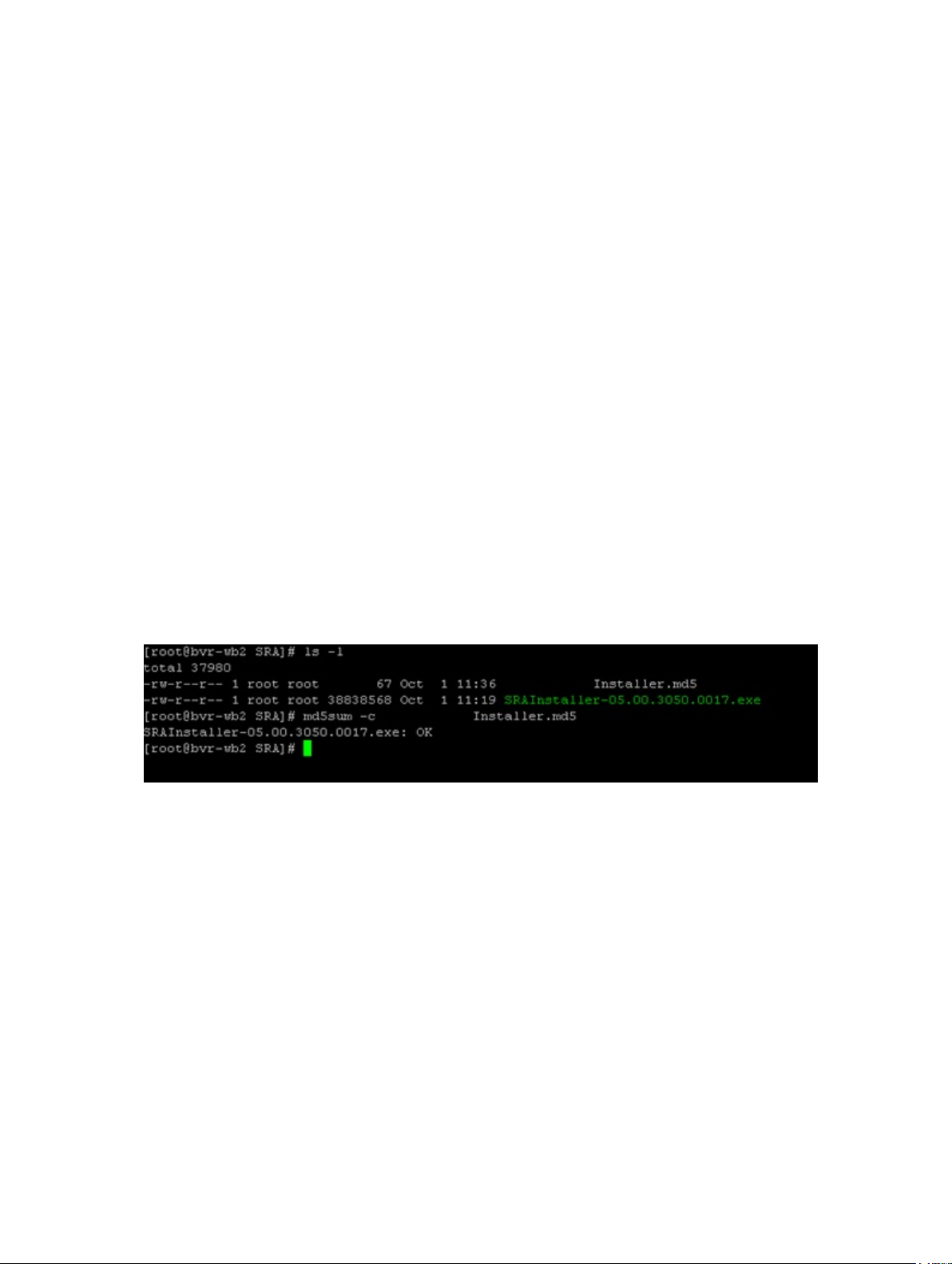
Md5sums may be calculated on any UNIX host with md5sum installed or by obtaining a Windows utility like
md5sum.exe from etree.org/md5com.html and running the following command from a command prompt.
md5sum <file_name>
If the file is downloaded with the Installer, you can run the following command to verify the installer package.
SRAInstaller-05.10.3600.00xx.md5
Figure 1. Example MD5 Evaluation
Installation Procedure
After verifying that the downloaded file is complete and not corrupt, copy the installer to your intended SRM servers and
run the SRA installer on those servers. You can view the latest information contained in the readme.txt file at the end of
the installation by clicking Yes to view the readme.
SRA is installed at the following location:
On x64 hosts C:\Program Files (x86)\VMware\VMware vCenter Site Recovery Manager\storage\sra
On x86 hosts C:\Program Files\VMware\VMware vCenter Site Recovery Manager\storage\sra
After SRA is installed, rescan for SRAs from the Site Recovery manager in the vSphere Client.
5
Page 6
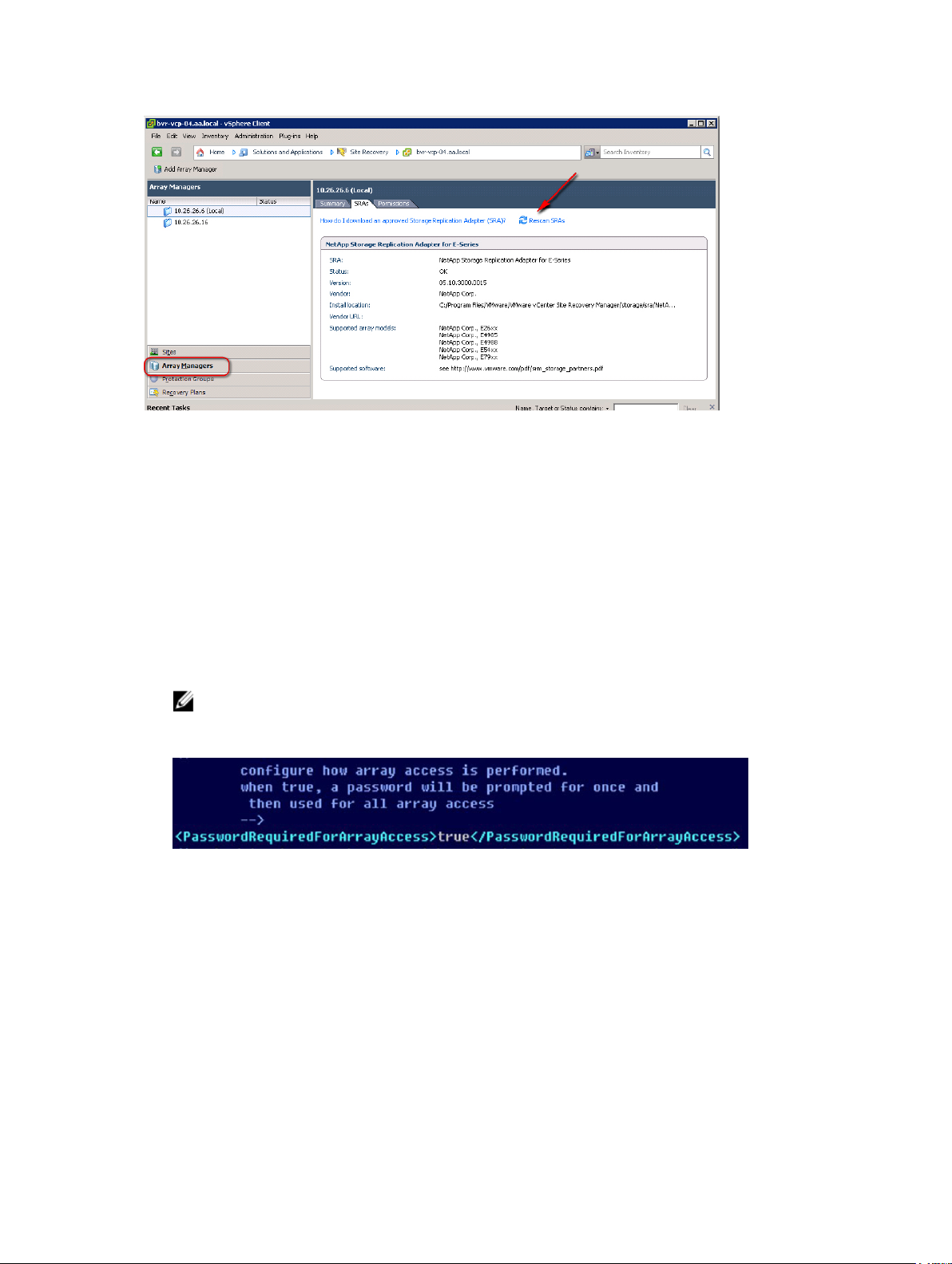
Figure 2. Site Recovery Manager (Rescan SRAs)
Password-Protected Storage Arrays
If your environment implements password security on the storage arrays, the SraConfigurationData.xml file must be
modified to prompt for storage array password.
To modify the files:
1. Edit the SraConfigurationData.xml file available at C:\Program Files (x86)\VMware\VMware vCenter Site Recovery
Manager\storage\sra\Dell\config\SraConfigurationData.xml
2. Locate the <PasswordRequiredForArrayAccess> tag.
3. Change the default value of false to true.
4. Save the file changes.
NOTE: All storage arrays must utilize the same security measures. If one storage array has a password set,
then the peer storage array must also have the password set. SRA does not support Mixed authentication
mode.
Figure 3. SraConfigurationData.xml Password Value
NVSRAM Settings
SRM test failover requires a change to the default NVSRAM settings on the MD storage array. During test failover,
snapshots are created on the recovery site's storage array which is then mapped to the default host group and the ESX/
ESXi host group.
To change the NVSRAM settings:
1. Start MD Storage Manager on your storage array.
2. From the Enterprise Management Window (EMW), select Tools → Execute Script.
6
Page 7
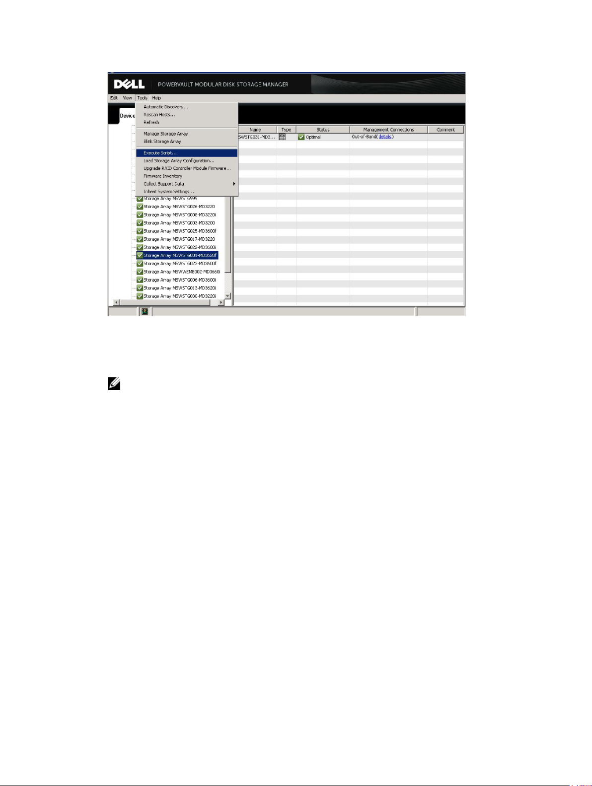
Figure 4. MD Storage Manager Execute Script
3. In the Script Editor window, to review your current NVSRAM settings, run the following command:
show controller[0] NVSRAMByte[0x3b];
NOTE: From the Script Editor window, you can use the Tools → Verify and Execute option to both test your
command syntax and execute your command.
Your current NVSRAM setting for the specified RAID controller [0] is displayed.
7
Page 8

Figure 5. Review Current NVSRAM Settings
4. Change the NVSRAM setting for your primary RAID controller [0] using the following command:
set controller[0] NVSRAMByte[0x3b]=2;HTTP/1
Figure 6. Change NVSRAM Setting on Primary RAID Controller
5. Confirm that your NVSRAM settings are changed by using the show controller command:
show controller[0] NVSRAMByte[0x3b];
8
Page 9

Figure 7. Confirm New NVSRAM Setting
6. Reset the primary RAID controller module to load the new NVSRAM setting into controller memory:
reset controller[0];
NOTE: The reset controller command takes several minutes to complete. Do not perform I/O operations
involving the RAID controller until the command successfully completes.
Figure 8. Reset Primary RAID Controller to Load New NVSRAM Settings
9
Page 10

7. Repeat Step 3 through Step 6 on the secondary RAID controller by substituting [1] for [0] in the command syntax
examples shown.
8. Close the Script Editor window.
SRA Device Management Service
The process monitors and synchronizes communications between the MD Storage Replication Adapter (SRA) and the
MD storage arrays. Site Recovery Manager (SRM) workload is partitioned between a persistent server and multiple
transient client programs which endure only during a single SRM command. Since multiple SRM commands are likely to
be executed during a single SRM workflow (for example, test failover), clients are used frequently. Servers, however,
running as a Windows Service, persist and manage all communications with storage arrays.
No special configuration other than default values is needed for the server. However, two files can be edited to control
host configuration, socket communication and virtual machine memory:
SraConfigura
tionData.xml
NesSvc.ini
This file resides in the /config directory under the SRA installation directory. The specific
location depends on your installation selections, the default location is C:\Program Files
(x86)\VMware\VMware vCenter Site Recovery Manager\scripts\SAN\Dell
\SraConfigurationData.xml .
This Win32 Service initialization file resides in the /win32svc directory under the same SRA
default installation directory as the SraConfigurationData.xml.
Changing Server Settings In SraConfigurationData.xml
The portion of SraConfigurationData.xml file relevant to service configuration is:
<SraService>
<SvcHost>localhost</SvcHost>
<ServicePort>1701</ServicePort>
<ListenBacklog>100</ListenBacklog>
<SraService>
<SvcHost>
<ServicePort
>
<ListenBackl
og>
Specifies which host the Win32 Service initialization file (NesSvc) runs on. Currently, the only
supported value is localhost. In future releases, it may be possible to share instances of
NesSvc across multiple installations of SRA, which would enhance performance and simplify
cooperation between multiple SRA instances.
Determines which IP port the service uses for socket communications between the client and
server. If another application on your system is already using port 1701 (default port), specify a
different port.
Configures a performance property of the port.
NOTE: Modify <ListenBacklog>only in consultation with Dell technical support
personnel.
Changing Virtual Memory In NesSvc.ini
No modifications are necessary to the Windows service initialization file (NesSvc.ini). If recommended by Dell technical
support personnel, virtual memory settings can be changed to:
10
Page 11

vmarg.1=-Xms256m
vmarg.2=-Xmx512m
NOTE: Any changes to the NesSvc.ini file requires you to stop and restart the service in order for the changes to
take effect.
11
Page 12

12
Page 13

2
Asynchronous Remote Replication
From RAID controller firmware version 07.84.44.60, MD Storage Replication Adapter (SRA) supports asynchronous
remote replication groups. This feature performs remote replication using Point-in-Time (PiT) snapshots and is
supported on both Fibre Channel and iSCSI MD storage arrays.
iSCSI-Based Remote Replication
With added support for Remote Replication over iSCSI protocol, greater replication distances are now possible.
However, this improvement in replication distances impacts latency (vs. previous Fibre Channel-only support).
Therefore, careful consideration should be taken during Datastore creation to ensure that only data that must be
replicated is included on the virtual disks you replicate. Once replication begins, closely observe the amount of data
being replicated and the time it takes to synchronize data. If the amount of time required to synchronize data is more
than the synchronization interval, a remote replication group becomes degraded and non-functional.
Proper sizing of your network infrastructure is a critical component of a successful disaster recovery solution. For more
information, see the following documentation:
•
Dell PowerVault MD-Series Storage Arrays Administrator's Guide
• VMware Site Recovery Manager Documentation Center at vmware.com/support/pubs.
Support For Four Remote Replication Groups
at dell.com/support/manuals.
SRA supports up to four Remote Replication groups per storage array. All protected Datastores must reside in one of the
four groups. Since a Remote Replication group is treated as a single entity, any action affecting the group (for example,
swapping roles) affects all virtual disks in the group. If cross-replication of Datastores is required (for example,
replicating from the recovery site to protected site), the Datastore virtual disks for the recovery site must be contained in
a separate Remote Replication group than the virtual disks on the protected site.
Impact Of 10-Minute Synchronization Interval
Remote replication groups require a 10-minute interval between automatic and manual synchronizations. If you request
a manual synchronization while a Remote Replication group is inside of a 10-minute synchronization interval, the manual
synchronization does not begin until the previous synchronization interval has passed. This may cause a delay in the
SRM workflow process which requires several synchronization operations to occur during test failover and/or failover
workflows. SRA is optimized to avoid requesting a manual synchronization if no changes are detected within the Remote
Replication group. However, if changes are detected, a synchronization is requested. The effect may be observed as a
lack of progress or slow progress through SRM workflows.
General Volume Recommendations
When designing a disaster recovery strategy using VMware Site Recovery Manager and MD Series storage arrays,
keep in mind these considerations:
13
Page 14

• Protection works on a datastore level (storage array virtual disk). All virtual machines on the same datastore
that requires protection are also protected and replicated.
• Multiple small-sized datastores and virtual disks must be used to limit the amount of data replicated to the
recovery site.
• Locate (migrate) protected virtual machines to the same datastore and migrate any VMs that do not require
protection to other locations.
• SRM does not provide for application-consistent failover, but does provide VM-consistent failover. Therefore,
even with a successful failover of a VM, the applications that are running on the VM may not be in a consistent
state. More recovery methods may be required to return to normal operation.
• Only MD Series storage arrays running firmware versions 07.84.44.60 or later support asynchronous Remote
Replication groups. The groups are treated as consistency groups, so all virtual disks in the group is treated as a
single entity.
• Synchronization priority dramatically affects the speed of replication, assuming that sufficient bandwidth is
available between the protected and recovery storage arrays.
Command Line Options
SRA installs a command-line utility that provides the following functions:
• To stop the SRA service, run the following command:
<SRA_Path>\svrCmd.cmd
Restarting the SRA service requires a start command from Windows services.
• To track the SRA service and capture detailed logging for each command issued and received, run the following
command:
<SRA_InstallationPath>\svrCmd track on (enable)
<SRA_InstallationPath>\svrCmd track off (disable)
Log files are written to <SRA_InstallationPath>\track directory.
Advanced Settings In Site Recovery Manager And ESX/ESXi
The following advanced settings in Site Recovery Manager (SRM) are recommended for best performance when using
the MD-Series Storage Replication Adapter (SRA).
To establish these settings:
1. Click Sites in the SRM left pane, then right-click on your site name and select Advanced Settings.
14
Page 15

Figure 9. Site Recovery Manager Advanced Settings
2. Click storage and set the following values:
– storage.commandTimeout = 900
– storageProvider.hostRescanRepeatCnt = 2
– storageProvider.hostRescanTimeoutSec = 900
3. Click OK to save your changes.
4. Click storageProvider and set the following values:
storageProvider.fixRecoveredDatastoreNames = enabled
ESX/ESXi Host Settings
The following changes are recommended for ESX/ESXi host settings:
• Disk.MaxLUN — Set this value slightly larger than the number of LUNs mapped to the ESX/ESXi host. This
provides faster rescan operations by not scanning all 256 LUN possibilities.
• Disk.UseDeviceReset = 1
and
Disk.UseLunReset = 0
Disk.UseDeviceReset and Disk.UseLunReset are used together to indicate how device resets are
issued.
15
Page 16

16
Page 17

3
Snapshot Repository Sizing
A new feature of firmware 07.83 are Point-in-Time Snapshots. These provide the ability to roll-back snapshots to
previous point-in-time saves and optimize the data changes between snapshot images. This feature utilizes two
separate repositories to facilitate tracking of changes to the base volume. They are the Snapshot Group repository and
Snapshot Volume repository.
Snapshot Group Repository
The Snapshot Group repository is used to track data changes to the base volume (volume that the Snapshot Image was
created from). The Snapshot Group repository may contain multiple Snapshot Images (point-in-time records of base
volume). A Snapshot Volume is created from these images and can then be mapped to a host for access.
Figure 10. Modular Disk Storage Manager (MDSM) Snapshot Group View
Snapshot Volume Repository
The Snapshot Volume repository is used to track data changes to the Snapshot Volume, if read/write access is allowed.
Once a Snapshot Volume is mapped to a host for access any changes to the volume are tracked within this repository.
17
Page 18

Figure 11. MDSM Snapshot Volume View
How SRA Uses Snapshots
The MD-Series SRA utilizes Point-in-Time Snapshots if the feature is enabled on the storage array During test failover,
the SRA creates a Snapshot Group, Snapshot Image, and Snapshot Volume on the recovery site’s storage array for all
volumes contained in the protection groups being tested. This requires the creation of the two snapshot repositories
listed above and the default size for these repositories is 10% of the base volume(s) for each repository, for a total of
20% of the base volume size. This means that the amount of free capacity on the recovery site storage array must be
20% of the base volumes participating in the test failover. This value is controlled by the
located in the config directory under the installation directory, typically:
C:\Program Files (x86)\VMware\VMware vCenter Site Recovery Manager\scripts\SAN\Dell\SraConfigurationData.xml
The value is set with the xml tag <SnapshotBasePercentage>.
<!-SnapshotBasePercentage represents the initial size, expressed as a percentage
of volume size, of a snapshot which is formed for test failover.
-->
<SnapshotBasePercentage>10</SnapshotBasePercentage>
Depending on how the VMs are used during test failover, it is possible to fine-tune this value for your environment to
reduce the amount of free capacity needed for test failover. If the test VM residing on the recovery site ESX host does
not write extensive data to the Datastores and no synchronization (or minimal changes) occur between the protected
site volumes and the recovery site volumes during test failover, this value may be decrease to 2-5 to require even less
free capacity during test failover. The Snapshot Volume and Snapshot Group repositories are deleted during the cleanup
phase of test failover along with the Snapshot Image.
Because the Snapshot Volume is typically not used during the test failover process (little write activity), the size of these
repositories may be decreased to very small sizes in order to preserve free capacity on the recovery site’s storage
array. If a repository runs out of space during the test failover phase, the VMs on the recovery site loses access to the
Datastore and underlying volume affected by the out-of-space condition of the repository, but the protected site VM
functions as normal. These values are not recommended for Snapshot repositories used for other purposes. The sizes
and status of the repositories may be monitored from within the MDSM by selecting the All Logical Objects container
and then selecting Repositories in the drop-down box:
SraConfigurationData.xml file
18
Page 19

Figure 12. MDSM Snapshot Volume View
Details like available repository space, mode, or timestamps may be viewed by selecting the Snapshot Volumes or
Snapshot Groups in the drop-down box.
19
Page 20

20
Page 21

Getting Help
Related Documentation
NOTE: For all PowerEdge and PowerVault documentation, go to dell.com/support/manuals and enter the system
Service Tag to get your system documentation.
NOTE: For Dell Support Forums, go to en.community.dell.com/support-forums/default.aspx.
NOTE: For Dell Advanced Search , go to search.dell.com/index.aspx.
You product documentation includes:
4
Getting Started
Guide
Owner’s Manual Provides information about system features and describes how to troubleshoot the system and
Deployment
Guide
User's Guide Provides information on installing configuring the VMware Storage Replication Adapter 5.1.
Provides an overview of system features, setting up your system, and technical specifications.
This document is also shipped with your system.
install or replace system components.
Provides information about the deployment of the storage controllers, system requirements,
storage array organization, and utilities.
VMware Support Information
vCenter SRM
Documentation
vSphere
Documentation
(ESXi, ESX, and
vCenter Server)
VMware
Knowledge Base
(Searchable
Support Issues)
VMware
Communities
(Help Forums)
vmware.com/support/pubs/srm_pubs.html
vmware.com/support/pubs/vs_pubs.html
kb.vmware.com/selfservice/microsites/microsite.do
communities.vmware.com/index.jspa
VMware
Compatibility
Guide
vmware.com/resources/compatibility/search.php
21
Page 22

Documentation Feedback
If you have feedback for this document, write to documentation_feedback@dell.com. Alternatively, you can click on the
Feedback link in any of the Dell documentation pages, fill up the form, and click Submit to send your feedback.
Locating Your System Service Tag
Your system is identified by a unique Express Service Code and Service Tag number. The Express Service Code and
Service Tag are found on the front of the system by pulling out the information tag. This information is used by Dell to
route support calls to the appropriate personnel.
Contacting Dell
NOTE: Dell provides several online and telephone-based support and service options. If you do not have an active
Internet connection, you can find contact information on your purchase invoice, packing slip, bill, or Dell product
catalog. Availability varies by country and product, and some services may not be available in your area.
To contact Dell for sales, technical support, or customer-service issues:
1. Go to dell.com/contactdell.
2. Select your country or region from the interactive world map.
When you select a region, the countries for the selected regions are displayed.
3. Select the appropriate language under the country of your choice.
4. Select your business segment.
The main support page for the selected business segment is displayed.
5. Select the appropriate option depending on your requirement.
NOTE: If you have purchased a Dell system, you may be asked for the Service Tag.
22
 Loading...