

Page 1

Dell PowerVault MD Storage Array vCenter
Plug-in for VMware vSphere
Installation and Configuration Guide
Page 2

Notes, Cautions, and Warnings
NOTE: A NOTE indicates important information that helps you make better use of your computer.
CAUTION: A CAUTION indicates either potential damage to hardware or loss of data and tells you
how to avoid the problem.
WARNING: A WARNING indicates a potential for property damage, personal injury, or death.
Copyright © 2014 Dell Inc. All rights reserved. This product is protected by U.S. and international copyright and
intellectual property laws. Dell™ and the Dell logo are trademarks of Dell Inc. in the United States and/or other
jurisdictions. All other marks and names mentioned herein may be trademarks of their respective companies.
2014 - 01
Rev. A09
Page 3

Contents
1 Overview......................................................................................................................7
Installation Prerequisites........................................................................................................................7
Configuration Limitations And Scalability............................................................................................ 8
Localization Support............................................................................................................................. 8
Logs, Warnings, And Error Messages..............................................................................................8
Downloading The MD vCenter Plug-In................................................................................................8
Upgrading From A Previous Version...............................................................................................9
Application Server Requirements......................................................................................................... 9
Before You Install The MD vCenter Plug-In.........................................................................................9
Installing The MD vCenter Plug-In..................................................................................................... 10
2 Configuring The Application Server And MD vCenter Plug-In....................11
Configuring Application Server Memory.............................................................................................11
Configuring Storage Administrator Roles...........................................................................................12
Creating A Storage Administrator Role.........................................................................................13
Adding An Existing User To The Storage Administrator Role............................................................ 15
Non-Authorized Plug-In Use Message.........................................................................................16
MD vCenter Plug-In Security.............................................................................................................. 16
Accepting And Installing The Trusted SSL Certificate.................................................................. 17
Microsoft Enhanced Browser Security.........................................................................................20
MD vCenter Plug-in Import And Export Configuration File ............................................................. 22
Application Server Login for Configuration File...........................................................................23
Exporting The Configuration File..................................................................................................23
Importing The Configuration File................................................................................................. 23
Application Server User Management .........................................................................................24
3 Configuring The MD Storage Array For ESX/ESXi.......................................... 25
Grouping HBAs And Creating Virtual Hosts.......................................................................................28
Managing Bandwidth.................................................................................................................... 28
Configuring ALUA Support................................................................................................................. 30
Changing Your Default Multipath Policy......................................................................................30
Adding A SATP Claim Rule To Enable ALUA And Change The Multipath Policy To Round
Robin..............................................................................................................................................30
Network Configuration For iSCSI Storage..........................................................................................31
Network Configuration For MD-Series iSCSI Storage Arrays...................................................... 32
Network Configuration For MD-Series Fibre Channel Storage Arrays........................................32
Installing The SAS Provider Upgrade.................................................................................................. 32
Installing The SAS Provider Upgrade (ESX/ESXi 4.1 Servers Only)...............................................32
Page 4

Installing The SAS Provider (ESXi 5.0 and 5.1 Servers Only).........................................................33
Configuring SAS Support On ESX And ESXi Hosts.............................................................................34
Requirements For Using A SAS Host............................................................................................ 34
Creating A New User Login With Host Privileges (ESX And ESXi Servers)...................................34
Enabling Root Login From A Host Console (ESX Servers Only).................................................. 34
Enabling Root Login From A Host Console (ESXi Servers Only)................................................. 35
4 Configuring The ESX/ESXi Host.......................................................................... 37
Configuring ESX Host To Storage Array.............................................................................................38
5 Managing Storage Arrays Using The MD vCenter Plug-In Manager
View...............................................................................................................................43
Storage Array Manager Features........................................................................................................ 43
Adding Storage Arrays To The vCenter Plug-In Manager View.................................................. 43
Discovering Storage Arrays...........................................................................................................45
Using Asset Tags........................................................................................................................... 46
Managing Asset Tags.....................................................................................................................47
Removing Storage Arrays From The vCenter Plug-In Manager View.........................................48
All Storage Arrays Table View....................................................................................................... 48
Assigning Asset Tags And Values..................................................................................................49
Summary View.................................................................................................................................... 50
Editing Storage Array Properties................................................................................................... 51
Storage Array Event Log................................................................................................................52
Storage Array Configuration Backup............................................................................................52
Formatting Virtual Disks For vSphere........................................................................................... 54
Virtual Disks Decision-Making Schemes...................................................................................... 55
Virtual Disks View................................................................................................................................ 55
Creating A Virtual Disks Group..................................................................................................... 56
Dynamic Disk Pools.......................................................................................................................57
Creating A New Virtual Disk On Virtual Disks Group................................................................... 57
Creating A Thin Provisioned Virtual Disks.................................................................................... 58
Legacy Snapshots..........................................................................................................................58
Mappings View....................................................................................................................................60
Mapping A Virtual Disks To Host...................................................................................................61
Rescan Storage Adapters...............................................................................................................61
Adding Host To Virtual Disks........................................................................................................ 63
Adding Host Group....................................................................................................................... 63
Virtual Disks Copy View...................................................................................................................... 63
Creating A New Virtual Disks Copy.............................................................................................. 64
Synchronous Replication View...........................................................................................................66
Creating Remote Virtual Disks Replication...................................................................................67
Removing Replicated Pairs........................................................................................................... 68
Page 5

Testing Replication Communication............................................................................................69
Suspending Asynchronous Replication........................................................................................69
Resuming Replication................................................................................................................... 69
Changing Replication Roles..........................................................................................................69
Changing Replication Parameters................................................................................................ 70
Snapshots View................................................................................................................................... 70
Creating Snapshot Group..............................................................................................................71
Creating A Snapshot Image...........................................................................................................72
Creating A Snapshot Virtual Disks.................................................................................................72
Changing Snapshot Settings......................................................................................................... 73
Asynchronous Remote Replication View...........................................................................................74
Asynchronous Remote Replication.............................................................................................. 75
Creating Asynchronous Replication Group..................................................................................75
Creating Replicated Pairs.............................................................................................................. 76
Changing Roles..............................................................................................................................77
Suspending Asynchronous Replication........................................................................................ 77
Resuming Replication................................................................................................................... 78
Manually Resynchronizing A Replication Group..........................................................................78
Deleting Replication Groups.........................................................................................................78
Removing Replicated Pairs............................................................................................................79
Datastores View.................................................................................................................................. 80
Manually Unregistering The MD vCenter Plug-In..............................................................................81
Uninstall The MD vCenter Plug-In................................................................................................82
6 Troubleshooting MD vCenter Plug-In Issues..................................................83
Application Server Logs...................................................................................................................... 83
vSphere Client Stops Working With Large Number Of Arrays.................................................... 83
I Cannot Communicate With The Application Server................................................................. 84
I Cannot Create Or Delete Objects..............................................................................................84
How Can I Maximize Client Performance....................................................................................84
How Do I Suppress Slow Script Warning Messages.................................................................... 84
Why Can I Not Make Changes To The Storage Array..................................................................84
The MD vCenter Plug-In Does Not Show The New Storage Array Name After A Clear
Configuration Operation In MDSM.............................................................................................. 84
Long Timeout For SAS ESX Host Wizard Operation.................................................................... 85
Storage Administrator Privileges Assigned To User Group Not Working................................... 85
Event Log Viewer Scroll Bar Goes Beyond The Limit.................................................................. 85
7 Getting Help.............................................................................................................87
Related Documentation......................................................................................................................87
VMware Support Information............................................................................................................. 87
Contacting Dell................................................................................................................................... 87
Page 6

6
Page 7
1
Overview
NOTE: Unless otherwise noted, later references to "MD Storage Array vCenter Plug-in" or "MD
vCenter Plug-in" in this document are used interchangeably to represent the MD VMware vCenter
Plug-in.
The Dell PowerVault MD Storage Array vCenter Plug-in allows integrated management of Dell MD series
storage arrays from a VMware vSphere client. Enabling a single vSphere-based management interface
eliminates the need to install, maintain and learn to use proprietary storage array-based management
tools. Using the MD vCenter Plug-in, an administrator can:
• Configure ESX/ESXi hosts to connect to MD storage arrays
• Create and delete Virtual Disks
• Map Virtual Disks from the storage arrays to the ESX host
• View the vCenter datastores available to the MD storage array's Virtual Disks
• Create hardware snapshots, Virtual Disks copies, and Remote Replication (Legacy) and Remote
Replication Group (if premium features are activated)
The MD vCenter Plug-in uses an application server interface between the vSphere Client and MD storage
array and fully supports role-based user authentication.
NOTE: The MD vCenter Plug-in requires that a vCenter Server must be installed.
Figure 1. MD vCenter Plug-In In a VMware Environment
Installation Prerequisites
The MD vCenter Plug-in requires the following:
7
Page 8

• VMware vCenter Server 5.x (installed on host server)
• One of the following servers operating systems to host the application server:
– Windows 2008 R2 SP1 Server
– Windows Server 2012
– Windows Server 2012 R2
– Red Hat Enterprise Linux 5.9 or later (x64)
– SUSE Enterprise Linux 11 or later (x64)
• Make sure your MD storage has the latest RAID controller firmware version installed.
For information on installing the correct MD series firmware version for your specific storage array, see
the Support Matrix at dell.com/powervaultmanuals.
Configuration Limitations And Scalability
The number of managed storage arrays, Virtual Disks and physical disks on each storage array impacts
the overall performance of the MD vCenter Plug-in. This release allows for organization of storage arrays
into panels to provide quick access to specific storage arrays based on user defined asset tags. Larger
numbers of managed storage arrays (more than 2000) will require more than 4 GB of RAM on your
application server platform. For more information on support limitations, see the Support Matrix at
dell.com/powervaultmanuals.
Localization Support
The MD vCenter Plug-in supports the following language sets:
• English
• French
• German
• Japanese
• Simplified Chinese
Logs, Warnings, And Error Messages
On-screen logs, warnings and error messages support the language sets shown above. However, any
messages or log files written to the file system are English only.
Downloading The MD vCenter Plug-In
From the application server, download the latest version of the MD vCenter Plug-in from the Download
and Drivers page at dell.com/support by selecting your specific MD storage array model. See the Support
Matrix at dell.com/powervaultmanuals for information on supported firmware levels, operating system
versions, and other supported hardware components.
NOTE: If you cannot access dell.com/support from your application server, download the MD
vCenter Plug-in installer to another host, then copy the installer files to the application server. The
Plug-in installer must be run from the application server itself.
8
Page 9

Upgrading From A Previous Version
If you are upgrading from a previous version of the MD vCenter Plug-in but plan to use the same host
server as the application server, run the latest installer on the current application server. The installation
wizard will prompt for an administrator password before unregistering and upgrading your MD vCenter
Plug-in version.
Application Server Requirements
The Windows-based application server configured with vCenter Client should be installed on a separate
server installation than the one running vCenter Server. While it is possible to install the application server
and vCenter Server on the same host, it is not recommended.
Before You Install The MD vCenter Plug-In
Before installing the MD vCenter Plug-in, you need to know some specific information about your
storage array and network configuration. The following table shows the information you will need. Gather
this information about your specific environment before installing the MD vCenter Plug-in:
Table 1. Storage Array and Network Information
Component Information Needed
vCenter Server
vCenter Administrator
Storage Administrator
Application Server
MD Storage Array
MD Storage Array
Host Name:
DNS Names:
IP Addresses:
Username:
Password:
Username:
Password:
Host Name:
DNS Names:
IP Addresses:
Array Name:
Password:
IP Addresses:
Array Name:
Password:
IP Addresses:
9
Page 10

Installing The MD vCenter Plug-In
NOTE: The MD vCenter Plug-in must be installed on the application server. If you downloaded the
installer package to a different location, copy the installer files to the application server before
performing the steps shown here.
1. From the application server launch the MD vCenter Plug-in installer, choose your language and click
OK.
2. Review the copyright and introduction screens. To accept, click Next.
3. Read and accept the license agreement, then click Next.
4. Select an installation directory on the vCenter client or accept the default location. Then, click Next.
5. Review the installation summary and click Install.
6. When prompted, either change the port number of the Jetty server or accept the defaults (8084 and
8081
) and click Next.
NOTE: If the MD vCenter Plug-in will be installed on the same system as an active vCenter
Server with VMware Update Manager installed, port number 8084 must be changed to an
unused port number.
7. Change the IP address of the application server, if desired. The default IP address shown the installer
will be the IP address of the system it is running on. Click Next.
8. Enter the IP address of the host containing the vCenter Server installation (see table Storage Array
and Network Information). Then, click
9. If you want to enable e-mail alerts, enter the vCenter Server administrator e-mail address and click
Next.
Next.
NOTE: The MD vCenter Plug-in does not require a domain or domain controller configuration.
When installing the Plug-in, do not qualify your administrator user name with an alias (for
example, localhost). If you specify a fully qualified pathname, use the host name instead (for
example, hostname/username).
10. Enter the vCenter Server administrator user ID, then click Next.
11. Enter the vCenter Server administrator password, then click Next.
12. When the installation completes, click Done to close the installation wizard.
The installation automatically installs a Jetty application server and associated .jar files on your
application server and registers the MD vCenter Plug-in with the VMware vCenter Server.
10
Page 11
2
Configuring The Application Server And MD vCenter Plug-In
Once the application server and MD vCenter Plug-in are installed, verify that the MD vCenter Plug-in is
successfully registered with the vCenter server:
• Open the vSphere Client
• From the vSphere Client menu bar, select Plug-ins → Manage Plug-ins
• The Dell MD Storage Array vCenter Plug-in should be listed as Enabled
If the MD vCenter Plug-in is listed as disabled with an error message indicating that it cannot
communicate with the application server, verify the port number defined for the Jetty server is enabled to
pass through any firewalls in use. The default Jetty TCP port numbers are 8084 and 8081. The MD
vCenter plug-in icon should also appear in the Solution and Application section of the vSphere Client
home page.
Figure 2. vSphere Client Home Page
Configuring Application Server Memory
If more than 250 storage arrays will be managed from the MD vCenter Plug-in, then the application
server configuration file has to be modified. The application server by default is configured for 512 MB of
RAM usage.
To adjust the settings to support more than 250 arrays, modify the appserver64.ini file located on the
application server in the C:\Program Files\Dell\MD Storage Array VMware vCenter Plug-In\jetty.
1. Open the appserver64.ini file in a text editor.
2. Locate the vmarg.3=-Xmx512M line.
3. Change 512 to the number associated with the number of storage arrays to be managed.
4. Save the configuration file.
11
Page 12
5. Restart the Application Server service.
NOTE: If the application server is reinstalled, this setting will be reverted to the original setting
of 512 MB and must be edited again to adjust the application server memory for your
environment.
Figure 3. Configuring the Application Server Memory
Configuring Storage Administrator Roles
By default, any previously defined vCenter users will have no access to MD storage arrays. To create
either read or read/write permissions to the storage arrays via the MD vCenter Plug-in, the user’s role
must be modified.
12
Page 13
Creating A Storage Administrator Role
1. In the Administration area on the vSphere Client home page, click Roles.
A list of roles and usages is displayed.
Figure 4. MD vCenter Plug-in Roles List
2. Click the Add Role icon in the menu bar, or right-click and select Add from the pop-up menu.
The Add New Role is displayed.
13
Page 14
Figure 5. Add New Role
3. In the Name text box, enter a name for the new role.
4. From the Privileges list, select the access permissions you want to assign to this role.
NOTE: An administrator role is not editable. Therefore, if the administrator user will be used to
manage storage, a new role must be created and all necessary privileges added to that role. The
administrator user must then be added to this role, as described in the next section.
5. To assign Read Only or Read Write access permissions to the storage arrays, select the appropriate
permission.
14
Page 15
6. When finished, click OK.
NOTE: Existing non-administrator roles may be modified to include the new Storage
Administrator privileges created. However, an existing administrator role cannot be modified.
Adding An Existing User To The Storage Administrator Role
Use these steps to add existing users to the Storage Administrator role you created previously. Storage
Administrator roles can only be given to individual users, not to user groups.
1. From the Inventory area on the vSphere Client home screen, select Hosts and Clusters.
2. Select your vCenter server name from the left navigation pane.
3. Select the vCenter server element, and click the Permissions tab.
Figure 6. Permissions Tab For The Selected vCenter Server Element
4. Right-click in the permissions window and select Add Permission to add users to the role.
15
Page 16
5. Click Add to select the users need access to the storage arrays.
Figure 7. Assign Storage Administrator Role
6. Select the role you want to assign them from the drop-down box under Assigned Role.
7. Click OK to apply the permissions.
Non-Authorized Plug-In Use Message
When you create a new Storage Administrator role, you might have to restart the vSphere Client before
the role is recognized. When this happens, a message similar to that shown in the figure Non-Authorized
User Message is displayed. This may also occur if new roles are added for users who are not previous
members of a Read Only or Read Write Storage Administrator role.
Figure 8. Non-Authorized User Message
MD vCenter Plug-In Security
The MD vCenter Plug-in uses Secure Sockets Layer (SSL) to communicate securely between the vSphere
client and application server.
16
Page 17
Accepting And Installing The Trusted SSL Certificate
During the vCenter Server installation process, an SSL certificate is generated for the vCenter Server
system. If this certificate has not been added to the system's Trusted Root Certification Authorities (CA)
store, a Security Alert dialog box is displayed when you start the MD vCenter Plug-in.
Figure 9. SSL Security Alert Message
17
Page 18
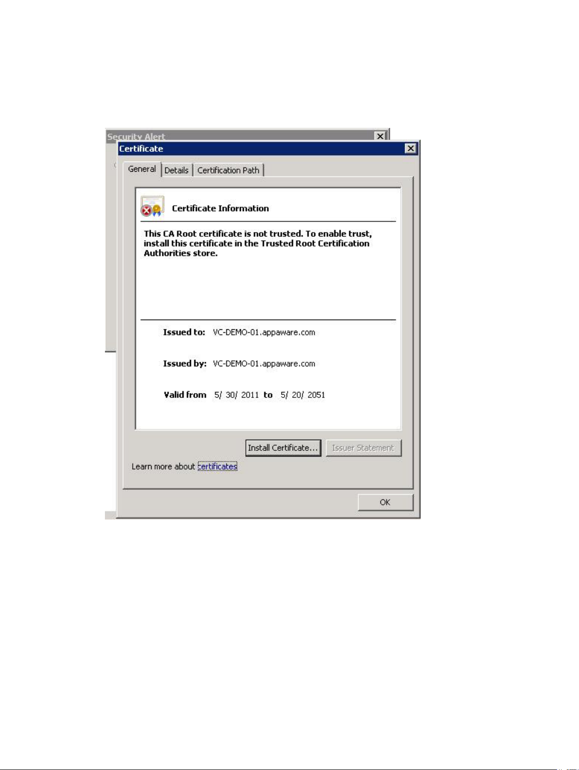
To avoid this message, you can import the install-generated certificate into the system's Trusted Root
Certification Authorities store using the following steps. However, if CA-signed SSL certificates are not
used, this alert message cannot be suppressed.
1. Click View Certificate.
Figure 10. Install Certificate Dialog Box
2. From the Certificate window, click Install Certificate.
18
Page 19
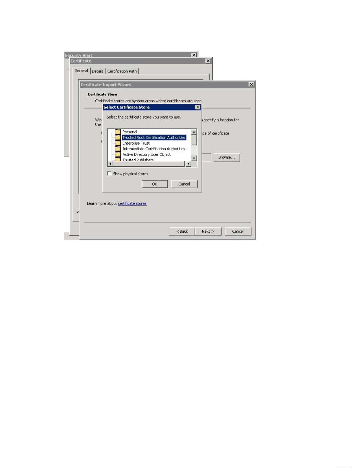
3. In the Certificate Import Wizard, click Next.
Figure 11. Select Certificate Store Dialog Box
4. From the Certificate Store window, select Place all certificates in the following store.
5. Click Browse.
6. In the Select Certificate Store window, highlight the Trusted Root Certification Authorities folder
and click OK.
7. Click Next.
8. Click Finish.
A Security Warning message box will be displayed.
19
Page 20
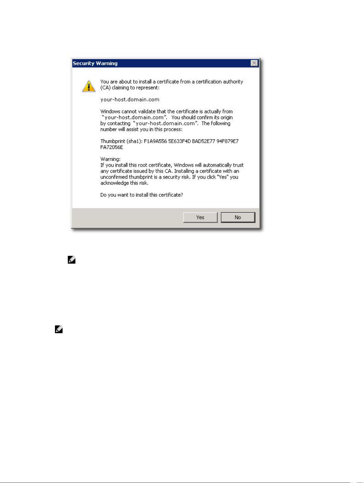
9. Verify the information and click Yes to add the certificate to the trust store.
Figure 12. Security Warning Message Box
NOTE: The subject name of the system in the certificate must match the system name of the
vCenter Server during the vSphere Client login screen. Otherwise, you will continue to receive
warning messages that the certificate does not match the site name.
Microsoft Enhanced Browser Security
When Microsoft's Enhanced Internet Explorer Security is installed on the vSphere Client system, the
security configuration blocks content from the web site and a warning message is displayed. Clicking Add
establishes a trust relationship with the application server.
NOTE: You may also be prompted to add about:security_VpxClient.exe to your Trusted sites (see
figure Microsoft Enhanced Security Message).
20
Page 21
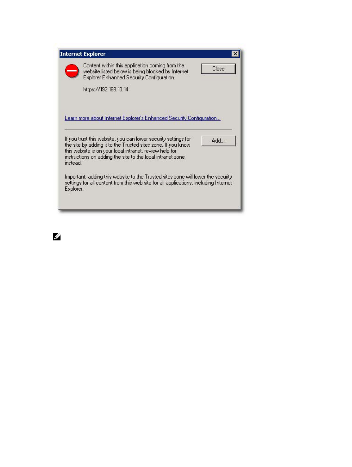
Figure 13. Microsoft Enhanced Security Message
NOTE: If you are using the Save File option, you will also need to add the DNS name or IP address
of the MD vCenter Plug-in application server in non-SSL format (for example, http://192.168.10.14)
as a trusted site.
21
Page 22
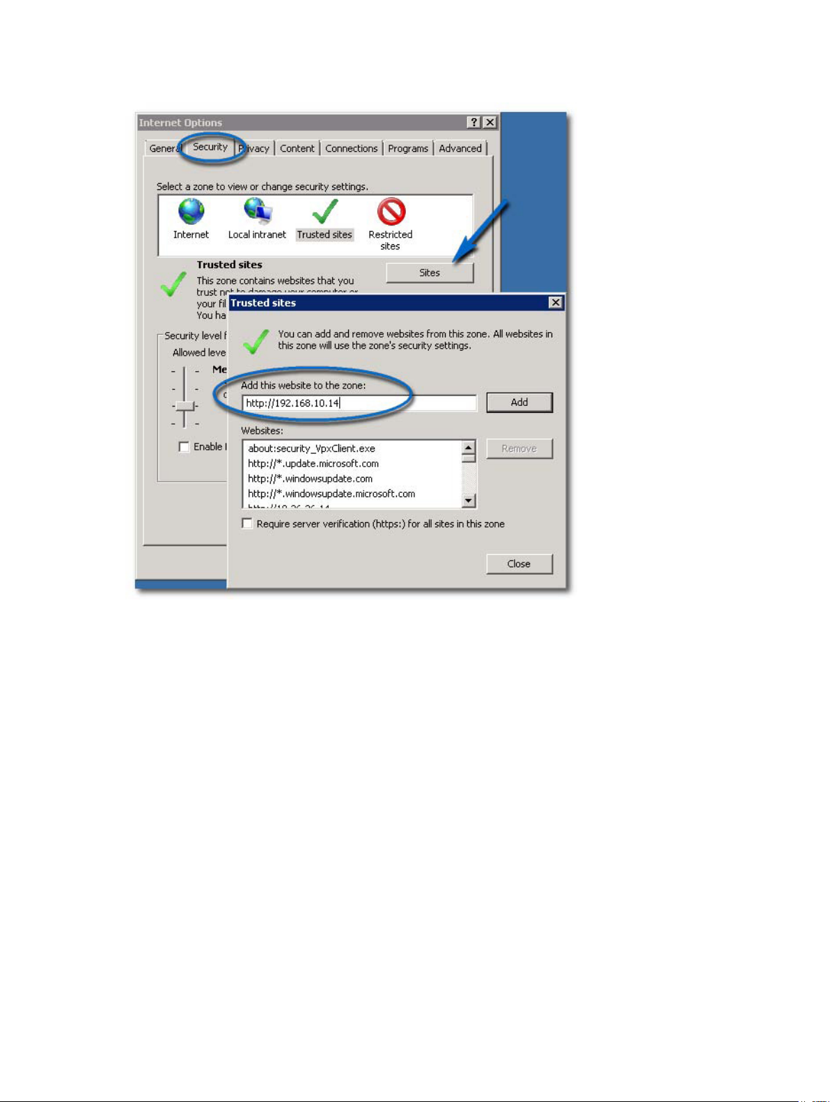
Figure 14. Microsoft Trusted Sites
MD vCenter Plug-in Import And Export Configuration File
The MD vCenter Plug-in provides the functionality to import or export the storage array manager
configuration file, that maintains the list of configured storage arrays and metadata information. This
feature is useful for backing up array configurations or deployment of new application server using an
existing configuration file. A web browser is required to utilize this functionality and access the
application server.
22
Page 23
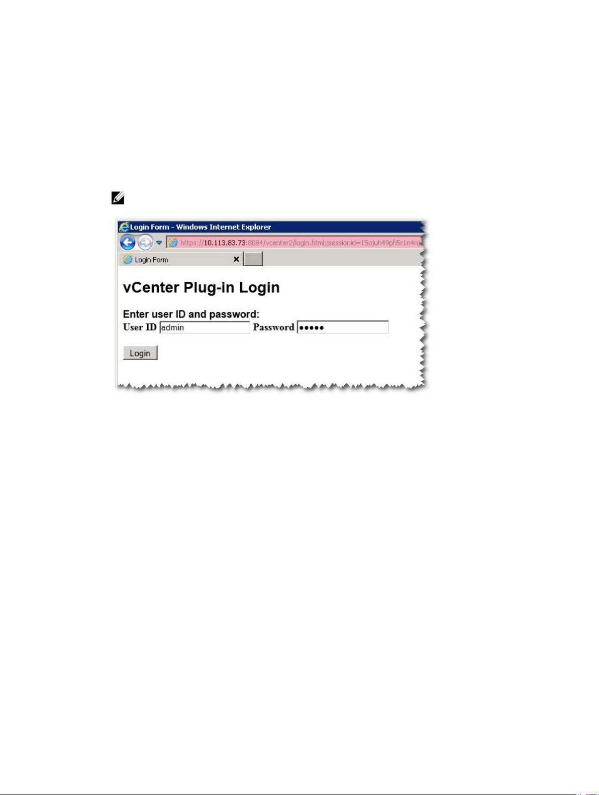
Application Server Login for Configuration File
To access the import-export page on application server:
1. Open the web browser and enter the application server URL.
For example:10.113.83.73:8084/vcenter2/ImportExportConfiguration.html
A login page is displayed.
2. Enter the MD vCenter Plug-in login credentials.
NOTE: The default login details are, User: admin and Password: admin.
Figure 15. Login Page
Exporting The Configuration File
To export the current configuration file:
1. Click the Export button.
2. Browse and select the location to save the configuration file to.
Importing The Configuration File
To import a saved configuration file:
1. Click the Browse button.
2. Navigate to the configuration file to import and click Open.
3. Select from the following Import Options:
– Merge with Existing File
– Overwrite Existing File
23
Page 24
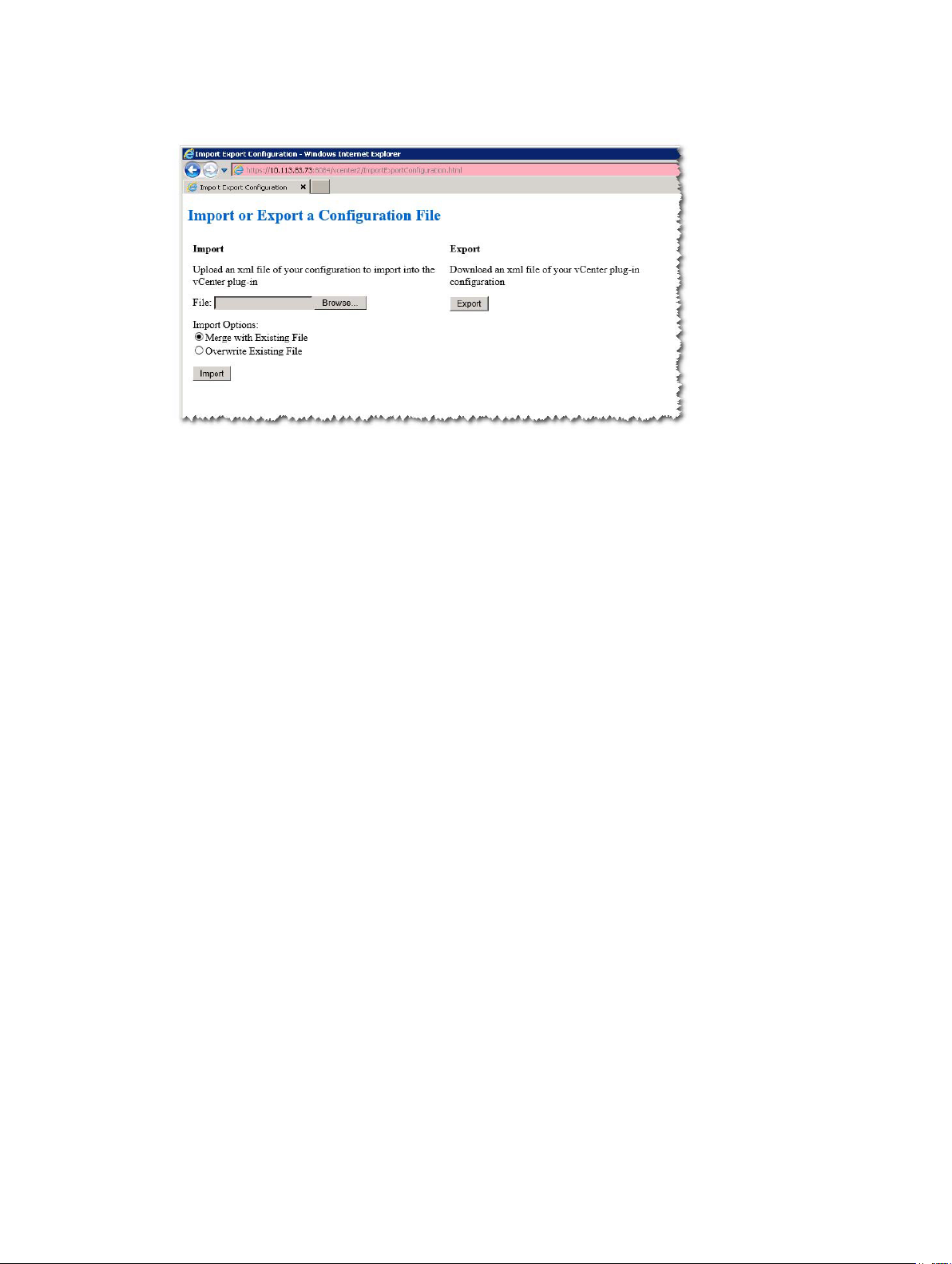
4. Click the Import button.
Figure 16. Importing and Exporting the Configuration File
Application Server User Management
The application server user management is controlled via the users.properties file located in C:\Program
Files\Dell\MD Storage Array VMware vCenter Plug-In\jettydirectory.
The format of the users.properties file is ID name, MD5 password hash, user ID.
#
#Thu Apr 11 18:02:33 PDT 2013
admin=MD5\:21232f297a57a5a743894a0e4a801fc3,admin
ro=MD5\:3605c251087b88216c9bca890e07ad9c,storage.ro
rw=MD5\:038c0dc8a958ffea17af047244fb6960,storage.rw
The passwords may be stored in clear text, but is not recommended. A MD5 password hash may be
generated from the following site: md5hashgenerator.com/index.php. Enter the password to be hashed
within the String textbox, then click Generate MD5 Hash. Copy the hashed results to the users.properties
file in place of the existing user password hash.
24
Page 25

3
Configuring The MD Storage Array For ESX/ESXi
The MD vCenter Plug-in allows an ESX/ESXi host to be automatically configured to use a Dell MD storage
array by detecting the installed Host Bus Adapters (HBAs) within the host and configuring new hosts on
the storage array with the Worldwide Names (WWNs) of the HBAs from the host. The default ESX/ESXi
multi-pathing mode for Dell MD storage arrays is Most Recently Used (MRU). To ensure optimum
performance for the ESX/ESXi host with more than two HBAs, the host should be configured to use the
storage array in pairs of HBAs. This method allows for maximum I/O throughput from the host to the
storage array. Using this method requires proper SAN configuration and balancing of LUNs between
hosts/host groups.
Figure Dual-Port HBA Configuration (Fibre Channel) shows a completely configured two-HBA ESX/ESXi
host Fibre Channel SAN configuration utilizing two fabric switches and a dual-controller storage array.
While this image shows a Fibre Channel configuration, the basic principles apply to all platforms. For
iSCSI-specific configuration details, see the topic Configuring iSCSI.
25
Page 26
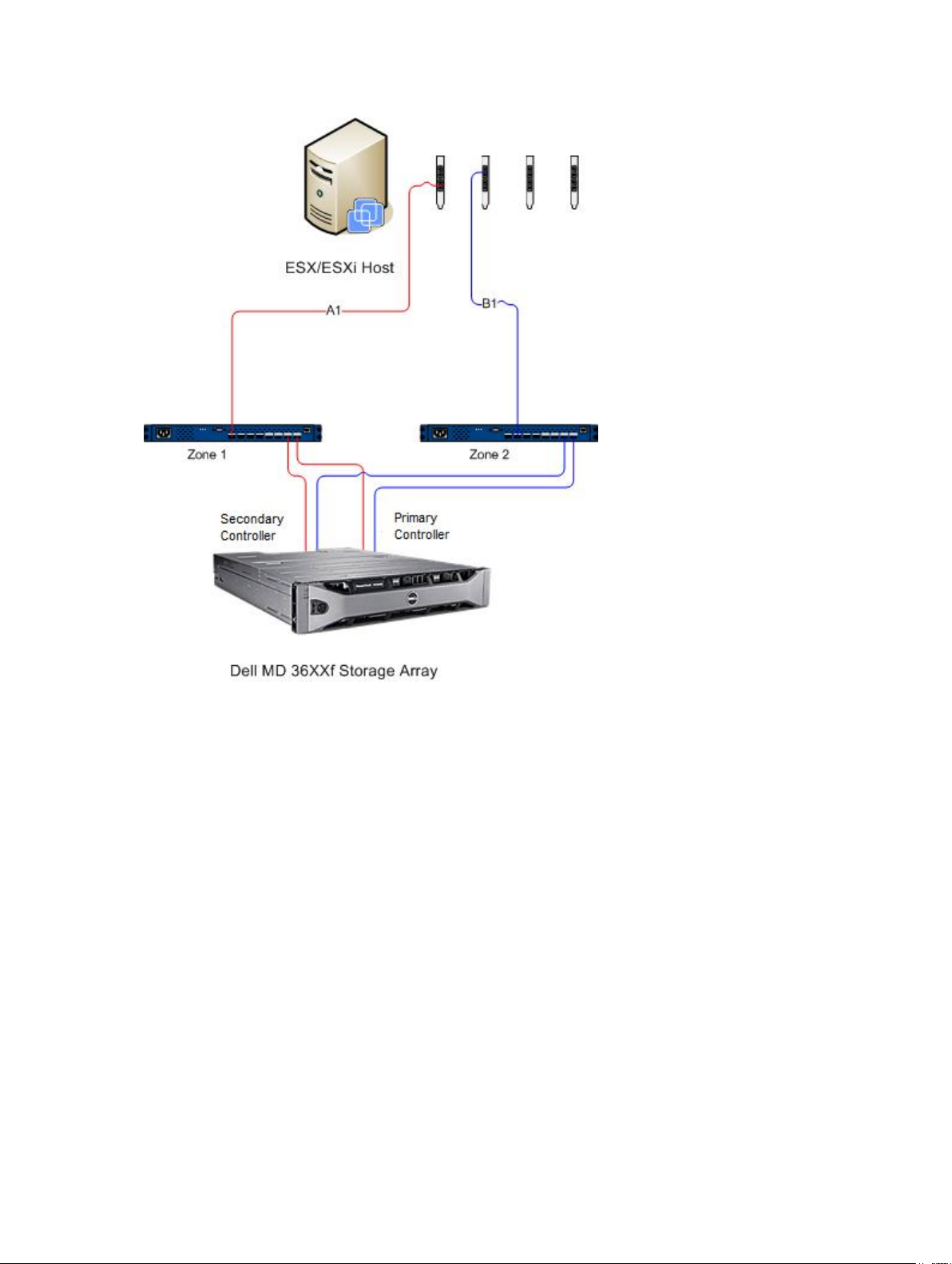
Figure 17. Dual-Port HBA Configuration (Fibre Channel)
This example shows a fully redundant fabric configuration. If a fibre channel switch or HBA fails, the
alternate switch still connects both storage controllers in the storage array. If a storage controller also
fails, the host can still access the remaining controller and all virtual disks fail over to that controller. A
complete loss of access to storage occurs if any other element fails.
26
Page 27
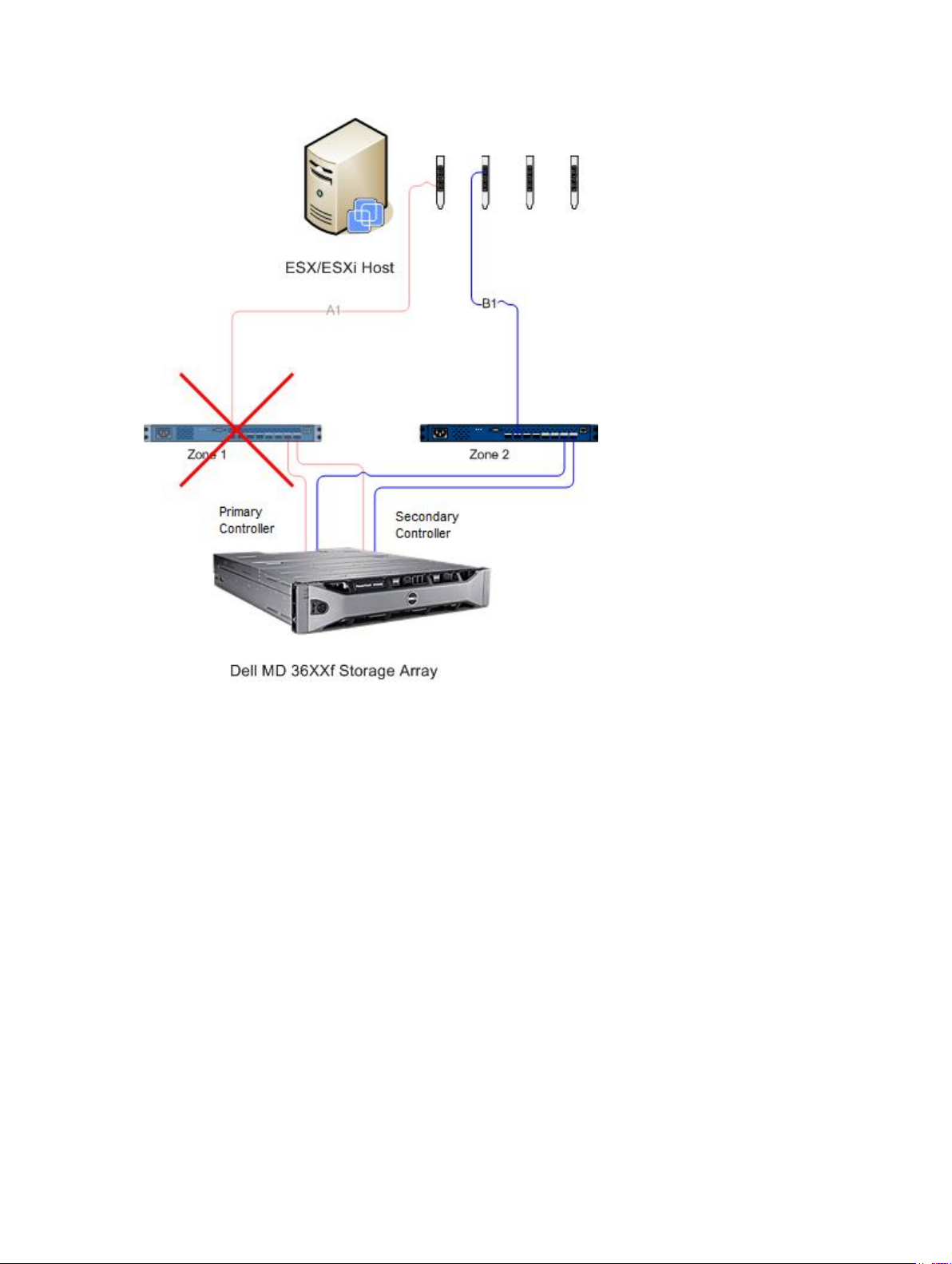
Figure 18. Configuration Showing Single-Point Failure
27
Page 28

Figure 19. Configuration Showing Double-Point Failure
While this method works well in the case of hardware failure, MRU only maintains one active path for
each HBA group. Therefore, if you have an ESX/ESXi host with four HBAs, only one HBA is active at a time.
Grouping HBAs And Creating Virtual Hosts
To achieve higher I/O throughput from the host to the storage array, group the HBAs in pairs and create
virtual hosts for each pair of HBAs. This allows for a fully redundant configuration, but also allows for two
of the HBAs to be active at the same time. From the storage array, the second pair of HBAs is defined as a
separate host. Then, virtual disks can then be mapped directly to the new host or host group. This same
methodology can be used to group additional HBAs in the same manner.
Managing Bandwidth
Grouping HBAs in pairs and using virtual disks to create a fully redundant configuration does require
additional management to balance the LUNs between the hosts/host groups and fully use available
bandwidth between all HBA groups. When this method is used in a fibre channel configuration, the
Automatic host configuration utility cannot determine which HBAs are configured to each fabric zone.
Instead, the administrator must verify that a single HBA is connected to both fabric zones for each HBA
pair group.
28
Page 29

Figure 20. Four-Port HBA Configuration
NOTE: The intent of this configuration is to pair the HBAs so that no group of HBA ports is
contained on a single HBA card (if dual-port cards are used).
For extending the configuration scheme, see the figure Eight-HBA Port Configuration.
29
Page 30

Figure 21. Eight-HBA Port Configuration
Configuring ALUA Support
If your MD storage array firmware supports Asymmetric Logical Unit Access (ALUA), active-active
throughput will enable LUN ownership to be transferred automatically to the alternate RAID controller in
a failure event.
Changing Your Default Multipath Policy
Depending on your environment, you may be able to achieve higher performance by switching the
default multipath policy from Most Recently Used (MRU) to Round Robin (RR). To identify the current
SATP claim rule and PSP policy used by your storage array, use the following command: #esxcli storage
nmp device list.
Figure 22. Device List Command Output
Adding A SATP Claim Rule To Enable ALUA And Change The Multipath Policy To Round Robin
To create the new claim rule, use the following command: #esxcli storage nmp satp rule add -s
VMW_SATP_ALUA -V DELL -M array_model -c tpgs_on -P VMW_PSP_RR -e “Dell ALUA Claim Rule”.
Replace the array model with one of the following:
• MD32xx
• MD32xxi
30
Page 31

• MD36xxi
• MD36xxf
This command:
• Creates a new entry for the VMW_SATP_ALUA rule for any LUN matching the vendor and model ID (V DELL and -M array__model) you specified
• Switches the default path selection policy to round robin (-P VMW_PSP_RR).
NOTE: There are different methods to manage SATP claim rules. Your environment may require
different parameters to enable ALUA support. Refer to the VMware Knowledge Base for additional
information.
To verify that the new claim rule was created successfully, repeat the esxcli storage nmp device list
command.
Figure 23. Device List Command Output Following New Rule Creation
Network Configuration For iSCSI Storage
The Dell MD3600i-series and MD3600f-series storage arrays are not listed in the ESX/ESXi 4.x SATP
(Storage Array Type Plug-in) driver. Therefore, both storage array product IDs must be manually added to
the SATP to properly configure failover. Configuring the network manually creates a VMkernel port and
maps it to a physical network interface card (NIC) capable of handling the specific data traffic. Depending
on the number of physical NICs that you use, the networking setup can be different.
To configure iSCSI adapters with this wizard, iSCSI HBAs must already be defined within vSphere. This is
accomplished by configuring an iSCSI network and adding iSCSI software initiator under storage
adapters. For network configuration:
• Add a VMkernel network for iSCSI communication
• Select NIC(s) to use for iSCSI and configure
• From the Storage Adapters view, click Add and select Add Software iSCSI Adapter
Figure 24. Configuring Network for iSCSI Storage
31
Page 32

Figure 25. Adding Software iSCSI Adapter
Network Configuration For MD-Series iSCSI Storage Arrays
If you are using a Dell MD3600i-series or MD Dense iSCSI storage array with ESX/ESXi 4.x, run the
following commands before mapping any virtual disks from the iSCSI storage array to the host.
• From the ESX/ESXi console #esxcli nmp satp addrule -v DELL -M MD36xxi -s VMW_SATP_LSI
• To verify that the storage array was successfully added to the driver list, run #esxcli nmp satp listrules |
grep DELL
For more information about network configuration for software iSCSI storage, see the iSCSI SAN
Configuration Guide: Configuring iSCSI Initiators and Storage: Setting Up Software iSCSI Initiators:
Networking Configuration for Software iSCSI Storage in the VMware vSphere Online Library.
Network Configuration For MD-Series Fibre Channel Storage Arrays
If you are using a Dell MD3600f-series or MD Dense storage array with ESX/ESXi 4.x, run the following
commands before mapping any virtual disks from the fibre channel storage array to the host:
• From the ESX/ESXi console, run #esxcli nmp satp addrule -v DELL -M MD36xxf -s VMW_SATP_LSI
• To verify that the storage array was successfully added to the driver list, run #esxcli nmp satp listrules |
grep DELL
Installing The SAS Provider Upgrade
The following section contains separate steps for installing the SAS provider upgrade, depending on
whether you are configuring an ESX or ESXi host.
Installing The SAS Provider Upgrade (ESX/ESXi 4.1 Servers Only)
Follow the steps below to install the SAS provider upgrade on ESX 4.1 servers:
1. Use either SFTP or SCP to copy the vmware-esx4.1-SAS-provider.vib file to your target ESX/ESXi
host.
2. Log in to the ESX/ESXi 4.1 host as root.
NOTE: If root is not enabled, log in as a shell-enabled user and run su to assume super-user
role.
32
Page 33

3. From the shell prompt, enter vmware -v to verify the ESX version as 4.1.
NOTE: If root is not enabled, log in as a shell-enabled user.4. Enter rpm -q lsi-provider.
4. For ESX/ESXi host version:
a) Enter rpm -q lsi-provider for ESX hosts.
b) Enter esxupdate --vib-view query | grep lsi-provider for ESXi hosts.
The version listed is lsi-provider-410.04.V0.24-140815.
5. Enter esxupdate -b file:$PWD/vmware-esx4.1-SAS-provider.vib --nodeps --nosigcheck --
maintenancemode update.
NOTE: The esxupdate command shown above assumes that the .vib file is located in your
current working directory. If it is not, replace $PWD with the directory location of the .vib file.
Several unpacking, installing, and cleanup messages are displayed.
6. When the installation is complete, run esxupdate --vib-view query | grep lsi-provider.
The following messages should be are displayed:
cross_lsi-provider_410.04.V0.24-260xxx pending,installed
cross_lsi-provider_410.04.V0.24-140815 retired
7. Stop any running virtual machines.
8. Reboot the host.
9. When the host reboot is complete, run the following commands to verify the update successfully
installed:
a) For ESX host: rpm -q lsi-provider .
b) For ESXi hosts: esxupdate --vib-view query | grep lsi-provider.
Installing The SAS Provider (ESXi 5.0 and 5.1 Servers Only)
Follow the steps below to install the SAS provider upgrade on ESX 5.0 and 5.1 servers:
1. Run SCP to copy the vmware-esx5.0-SAS-provider.vib file to your target ESXi host.
2. Log in to the ESXi 5.0/5.1 host as root.
NOTE: If root is not enabled, enable it temporarily for this installation.
3. From the shell prompt, enter vmware -v to verify the ESXi version.
4. Enter esxcli software vib install -v file:/vmware-esxi5.0-SAS-provider.vib -f --maintenance-mode on
the same command line.
NOTE: The esxcli command above assumes that the .vib file is located in the / directory. If it is
not, precede the command with the location of the .vib file.
The following messages are displayed:
– Installation Result
– Message: The update completed successfully, but the system needs to be
rebooted for the changes to be effective.
– Reboot Required: true
– VIBs Installed: LSI_bootbank_LsiProvider_500.04.V0.24-261033
– VIBs Removed:
– VIBs Skipped:
5. Stop any running virtual machines.
33
Page 34

6. Reboot the host.
7. When the host reboot is complete, run esxcli software vib list | grep LSI to verify that the upgrade was
successfully applied.
Configuring SAS Support On ESX And ESXi Hosts
To configure the MD vCenter Plug-in for ESX or ESXi hosts connecting to SAS-based Dell MD storage
arrays, the SAS SMI-S provider must be upgraded on the host.
NOTE: SAS is supported only on ESX/ESXi 4.1 or later hosts. Previous ESX/ESXi versions do not
support SAS-based storage array connections.
NOTE: This upgrade is only required to allow the Host to Storage Configuration option for
configuring SAS-connected storage arrays. If the storage arrays are already configured or are not
SAS-connected, the in-box provider does not need to be upgraded.
Requirements For Using A SAS Host
To use the SAS provider, make sure the following requirements are (or can be) met:
• The SAS provider must be deployed on the ESX/ESXi-based servers before connecting the storage
array
• Secure File Transfer Protocol (SFTP) or Secure Copy (SCP) must be enabled on the ESX/ESXi host
• If you are installing the upgrade package via remote login, you must either create a new user with
host login privileges or enable remote login for the root user
Creating A New User Login With Host Privileges (ESX And ESXi Servers)
Follow the steps below to create a new user login with host privileges:
1. Connect the vCenter Client directly to the ESX/ESXi host you are configuring.
2. Click Home → Inventory → Inventory, select the Users and Groups tab.
3. Select a user, then right-click and select Add.
4. Enter the required user information and select Grant shell access to this user.
5. Click OK to save changes.
6. Log in as the new user, then run the su command to assume the super-user role.
Enabling Root Login From A Host Console (ESX Servers Only)
Follow the steps below to enable root login from an ESX host.
1. Log in as root.
2. Open the /etc/ssh/sshd_config file.
3. On the line that contains PermitRootLogin, change no to yes.
4. Save and close the file.
5. At a shell prompt, run the following command to reload the service: # service sshd restart.
34
Page 35

Enabling Root Login From A Host Console (ESXi Servers Only)
Follow the steps below to enable root login from an ESXi host.
1. Press F2 to switch to open the configuration menu.
2. Select Troubleshooting Options.
3. Select Enable Remote Tech Support.
4. Select Restart Management Agents.
5. Press Esc to close the Configuration menu.
35
Page 36

36
Page 37

Configuring The ESX/ESXi Host
To use the Automatic Host Configuration utility:
1. Navigate to Hosts and Clusters of the vSphere Client home page.
2. Select the host to be configured.
4
37
Page 38

3. Right-click the host and select Configure ESX Host to Storage Array.
Figure 26. ESX/ESXi Host Configuration Menu
Configuring ESX Host To Storage Array
The Configure ESX Host to Storage Array wizard allows you to see how the current host is configured to
the storage array (if already configured). You can also use this wizard to add, remove or rename a host or
host group, or automatically configure the host to another storage array.
38
Page 39

Figure 27. Configure Host to Storage Array View
This wizard walks you through the process of configuring HBAs on ESX/ESXi hosts to the storage arrays
you configure in the plug-in array manager. It also provides additional information needed to detect and
configure SAS HBAs on the ESX/ESXi hosts.
NOTE: By default, the wizard will only display hosts that are prefixed with ESX_ and host groups
prefixed with VMware_. To display others, select the Show all host groups as described in step 7.
1. After reading through the introduction screen, click Next.
The Inspect Configuration process begins. This verifies user privileges and gathers information on the
selected host and any configured storage arrays. This process may take a few minutes, depending on
the number of adapters and storage arrays configured. After all discovery processes are complete,
three green check marks are displayed.
2. On the Select Host HBAs window, select the host HBAs to be configured.
3. Select the interface type and all HBA ports to be configured on the target storage array.
4. The Select Storage Array page allows you to select the storage array that will be used by the ESX
host.
39
Page 40

5. The Suggested Configuration page displays recommended HBA port configurations, host
configuration and host group configurations. Suggested changes are displayed in blue italics (see
Figure Suggested Host Configurations).
– To accept the suggested configuration, click Next. Go to step 10 to complete the configuration.
– To manually configure the host, select Use manual configuration and continue to step 6.
Figure 28. Suggested Host Configurations
6. If Use manual configuration is selected, the Manual Configuration page will be displayed. If the ESX
host will be participating in a cluster configuration with other ESX hosts and no existing host group
exists for the cluster configuration, select the storage array name and click Add Host Group.
7. Enter the name for the new host group and click OK. If the host group for the cluster already exists,
check the Show all host groups option and select the host group name you want to add this host to.
To use multiple host groups, the storage array must have the Storage Partitioning premium feature
enabled.
8. Click Add Host and enter the name for this ESX host.
9. Select the check boxes next to the HBAs to be used for the host definition (see Figure Manually
Adding a Host Dialog).
10. Click OK to complete host configuration.
A review page is displayed showing what changes will be applied to the storage array. If you are
satisfied with the changes, click Apply Changes.
40
Page 41

11. Repeat steps 8 through 10 for each pair of HBAs to be used for the ESX host.
Figure 29. Manually Adding a Host Dialog
NOTE: The Configure ESX Host to Storage Array wizard does not detect how the fibre channel
switch fabric is zoned. Suggested configurations are based on HBA ports detected and may
require the fabric to be rezoned based on your specific environment cabling.
You cannot rename or remove existing configured hosts or host groups. Existing host and host
group configuration changes must be performed from MD Storage Manager. Click Next after all host
groups and hosts have been defined. The Review Changes page is displayed showing what changes
will be applied to the storage array. Validate the changes and click Apply Changes button.
A real-time summary page is displayed showing the status of the changes being applied to the
selected storage array. Once the changes are applied, select Restart to repeat the configuration
process on another storage array, or select Close to close the configuration wizard.
NOTE: Multiple host groups can be used if Storage Partitioning premium feature is enabled.
By default, the wizard will only display hosts that are prefixed with ‘ESX_’ and host groups prefixed
with ‘VMware_’. Other hosts or host groups configured on the storage array will be displayed in the
in the wizard if Show all host groups option is selected.
41
Page 42

Figure 30. Apply Changes to Storage Array
42
Page 43

5
Managing Storage Arrays Using The MD vCenter Plug-In Manager View
This section describes how to use the storage array management features in the MD vCenter Plug-in.
Before continuing, make sure you have configured your host and storage array as described in the
preceding sections.
Storage Array Manager Features
To use the MD vCenter Plug-In to manage your storage arrays, click the MD vCenter Plug-in icon on the
vSphere Client home page in the Solutions and Applications section. The following features are available
in storage manager view:
• Add Storage Array
• Discover Array
• Edit Storage Array
• Refresh Storage Array
• Add Panel
• Manage Tags
• Remove Storage Array
Adding Storage Arrays To The vCenter Plug-In Manager View
NOTE: Add Array facilitates to add a single storage array to the array manager view and supply the
storage array password. It also provides the ability to assign asset tags to the new storage array. For
more information on adding multiple arrays, see topic Discover Array. The Add Array dialog fields
are limited to 30 characters. If you require a longer DNS name and cannot use an IP address, create
an alias to use in this dialog.
43
Page 44

To add a storage array using the MD vCenter Plug-in:
1. Click Add Array in the Commands area of the Array Manager view.
Figure 31. Add Storage Array
A dialog box is displayed showing DNS name/IP address text boxes for RAID Controller A and B, as
well as a Password field.
Figure 32. Add Storage Array Dialog
2. In Controller A (DNS or IPv4), enter the IP address or DNS name of RAID controller A on the storage
array.
3. In Controller B (DNS or IPv4), enter the IP address or DNS name of RAID controller B on the storage
array.
4. In Password, enter a password for the storage array you are adding to the MD vCenter Plug-in.
This password will be required by the MD vCenter Plug-in to access the storage array. It will not
change or override an existing storage array password set in Dell MD Storage Manager.
44
Page 45

5. Optionally, you can create unique asset tag keys and values for your storage arrays. For more
information, see the topic Organizing Storage Arrays.
6. Click Add to add the storage arrays.
7. Click Close when all storage arrays are added.
Discovering Storage Arrays
To add a storage array to the vCenter Plug-in using automatic discovery:
1. In the Commands area of the Array Manager view, click Discover Arrays.
2. In the Discover Storage Arrays window, enter the starting and ending TCP/IP address range on
which you want to discover.
Figure 33. Discover Storage Arrays
3. Click Discover to start the discovery scan.
Depending on the range specified, discovery may take up to several minutes.
After discovery completes, a list of discovered arrays are displayed.
4. Select the storage arrays to be added to the vCenter plug-in by clicking the checkbox(es) next to the
storage array name(s).
NOTE: If a same asset tags will be used for all the selected arrays, you can enter the asset tag
key and asset tag value in the fields provided and click Assign. For more information, see figure
Storage Array Organization.
5. If the same array password is used for all selected storage arrays, you can enter it in the Password
field at the bottom of the Discover Storage Arrays window.
6. Click Add to add all your selected storage arrays to the vCenter Plug-in Array Manager view.
7. Click Close when all storage arrays are added to the plug-in.
Edit And Refresh Option
Edit Option
The Edit option modifies the existing panels or storage arrays. Select the object to modify and click Edit.
Depending on the object selected, you will be able to modify the settings.
45
Page 46

Refresh Option
The Refresh option in the storage manager view, displays the configured storage arrays for status
changes. The storage array manager view automatically updates this view.
Using Asset Tags
Asset tags allow you to define custom characteristics for each storage array, such as city, state, row
number and type. Once an asset tag key and value are assigned to a storage array, a storage panel can be
created to automatically group all storage arrays matching the criteria specified for the panel.
Storage panels are created with specific asset tag values, or can be created with only an asset tag key.
Defining both creates a panel with all storage arrays having an asset tag value for the specified asset tag
key and automatically groups the storage arrays based on their asset tag values. You can also choose to
define a storage array panel with only a specific asset tag value. This will create a panel with only storage
arrays having the associated asset tag key and specific asset tag value defined within the panel.
Examples of different combinations of asset tag definitions are shown in figures Storage Array Panel
Configuration with All Asset Tag Values and Storage Array Panel Configuration with Specific Asset Tag
Value.
Figure 34. Storage Array Panel Configuration with All Asset Tag Values
46
Page 47

Using a wildcard character (*) in an asset tag value, the folder display will automatically create sub folders
based on the storage asset tag values as shown in figure. If you assign a specific value, no subfolders are
created.
Figure 35. Storage Array Panel Configuration with Specific Asset Tag Value
Managing Asset Tags
Asset tag keys and values can also be managed by selecting the Manage Tags link in the Commands area.
From the Manage Tags window, you can view all asset tag keys and tag values for a selected storage
array. Additionally, by selecting a tag key, you will see a list of storage panels using this tag key along with
a list of storage arrays assigned this tag key. The same is true for selecting a tag value. From this dialog
tag keys and tag values may be added, removed, or renamed.
Figure 36. Manage Tags Window
47
Page 48

Asset tag keys and values must not be removed from individual storage arrays from this window.
Removing Storage Arrays From The vCenter Plug-In Manager View
Storage arrays may be removed by either selecting the individual storage array in the Array Manager
Folder view or by selecting the All Storage Arrays object. Selecting the All Storage Arrays object will
display a window of all storage arrays currently configured, that may be individually selected for removal.
Selecting an individual storage array within the folder and clicking Remove will display a confirmation
dialog message for removal of the selected array.
The Remove option may also be used to remove existing panels by selecting the panel to be removed.
To remove a storage array using the MD vCenter Plug-in:
1. In the vSphere Client Storage Array Manager view, select the All Storage Arrays folder.
2. Click Remove in Commands area.
The Remove Storage dialog box is displayed.
Figure 37. Remove Storage Arrays
3. Select the storage array you want to remove and click Next.
A confirmation window is displayed with a list of storage arrays to be removed. Click OK.
4. Click Finish to confirm.
All Storage Arrays Table View
The All Storage Arrays table view displays all storage arrays in a list that can be customized by selecting
the drop-down arrows from the column headers and selecting which columns to display.
48
Page 49

Figure 38. Storage Array Table View
Assigning Asset Tags And Values
Asset tags are custom data tags that can be associated with each storage array. They provide a method
for sorting and organizing storage arrays based on your environment and needs.
To define and assign an asset tag value to a storage array:
1. Select a storage array in the All Storage Arrays list.
2. Click Edit in the Tag Assignments area.
An Edit Storage Array window is displayed.
Figure 39. Assigning Asset Tag and Values in Edit Storage Array Dialog
3. Enter an asset tag key or select an existing key in the Tag key field.
4. Enter an asset tag value or select an existing value in the Tag value field.
5. Click Assign to add them to the storage array.
6. If you want to assign multiple keys or values to the same storage array, repeat steps 3 through 5.
7. Click Save to apply changes.
49
Page 50

Changing The vCenter Plug-In Password
Follow these steps to change the vCenter plug-in password:
1. Open the Array Manager View.
2. Click the name of the storage array in the left plane.
3. Click Edit Storage Array, in the right pane.
The Edit Storage Array dialog box is displayed.
4. Enter the new vCenter Plug-in password in the Password field.
5. Click OK.
6. Click Verify Password, to verify that the password you entered matches the password on the storage
array.
A green or yellow icon will be displayed.
NOTE: This password is used by the plug-in only and will not change or override a storage array
password set in MD Storage Manager. For more information, see the topic Resolving a
Password Mismatch Between The MD Storage Array And The vCenter Plug-In .
Resolving A Password Mismatch Between The MD Storage Array And The vCenter Plug-In
If the MD vCenter Plug-in password and the storage array password do not match, you can still run
passive, read-only commands (such as Read and View) on the storage array. However, active read/write
commands (such as Create and Delete) will fail. The MD vCenter Plug-in will display the properties of the
storage array whether passwords match or not.
Summary View
When a storage array is selected under the All Storage Arrays view on the left side of the plug-in window,
the Summary tab displays information for that array, including array name, status of the storage array, the
number of controllers, the number of failed controllers, the number of drive trays, the number of disks,
disk types, hot spares, and capacity usage. The storage array Summary tab also provides the following
functions:
• Edit Storage Array
• View Event Log
• Refresh
• Automatically Save Configuration
• Manually Save Configuration
50
Page 51

Figure 40. Summary Tab View
Editing Storage Array Properties
The Edit Storage Array feature on the Commands area allows you to change a storage array’s IP
addresses, defines a password, verify the password entered matches the password configured on the
storage array, and manage asset tag keys and values for selected storage array.
Figure 41. Edit Storage Array Dialog
51
Page 52

Storage Array Event Log
The MD vCenter Plug-in allows you to view the Event Log for a storage array.
NOTE: If the file is locked, you can create a copy of the file with a different name, then open the
copied file.
Accessing The Event Log
To access the event log:
1. Click View Event Log in the storage array Summary window.
You can set filters in the Event Log to show events (all or only critical), view details for a selected
event and specify the number of events to retrieve. By default, the Event Log retrieves the most
recent 100 events. However, from the Retrieve the most recent events drop-down list, you can
specify a specific number of events to retrieve.
2. After making any changes to the Event Log Viewer, click Update.
Figure 42. Event Log Viewer
3. After changing the MEL settings, click Save as, and click Close.
Storage Array Configuration Backup
The MD vCenter Plug-in supports configuration backups to script files that may be applied to a storage
array from the Dell MD Storage Manager (MDSM). These script files will facilitate the restoration of the
storage array configuration, such as storage array name, disk group configurations, virtual disk names,
and virtual disk capacities. IT WILL NOT BACKUP DATA RESIDING ON THE STORAGE ARRAY. A traditional
backup strategy must be employed to provide recovery of data residing on the virtual disks.
CAUTION: Only the storage array configuration information is saved during the save
configuration operation. No data stored on the virtual disks is saved. Additionally, only the base
storage array configuration information is saved. Objects such as snapshots, virtual disk copies
and remote replications are not saved to the script file.
The MD vCenter Plug-in Automatic Save Configuration will perform a save configuration of the storage
array after a configuration event has occurred on the storage array, either from the MD vCenter Plug-in
52
Page 53

or from MDSM. A storage array modification event will start a four-minute timer on the application server.
If, within that four-minute time window, no other configuration events have occurred on the storage
array, a save configuration will occur. If another modification event occurs within the four-minute time
window, the timer resets to four minutes. When no modification events are detected on the storage array
within the four-minute window, a save configuration will be performed. Automatic Save Configuration
will maintain the last 15 save configuration script files.
Enabling Automatic Save Configuration Backups
These backups can be set to be automatically or manually initiated.
To enable automatic backups of the storage array base configuration, perform the procedure below:
1. Open the Array Manager view.
2. In the left pane, select the storage array name.
The storage array properties are displayed in the right pane.
3. In the Summary tab, click Automatically Save Configuration.
The Automatically Save Configuration dialog box is displayed.
4. Check Enable automatic save configuration.
5. Click OK to enable automatic configuration backups.
Once automatic configuration backups are enabled, they are persisted between restarts of the MD
vCenter Plug-in application server and vCenter Server. To disable automatic save configuration, clear
the selection box.
Figure 43. Automatic Save Configuration Message
NOTE: The automatic backup script files are located in C:\Program Files (x86)\Dell\MD Storage
Array vCenter Plug-In\jetty\savecfg directory.
Initiating A Manual Save Configuration
To perform a manual save configuration:
1. Open the Storage Array Manager view.
2. In the left pane, click the storage array name.
The storage array properties are displayed in the right pane.
53
Page 54

3. In the right pane, click Manually Save Configuration.
The Manually Save Configuration dialog box is displayed.
Figure 44. Manually Save Configuration Message
4. Click OK.
Internet explorer will launch a File Download dialog box.
5. If a security alert notifies you that you are leaving a secure Internet connection, click Yes.
6. If your security settings block you from downloading the file, add the non-secured HTTP address for
your vCenter application server to your trusted sites list. For more information see MD vCenter Plugin Security.
7. Click Save.
A Save As dialog box is shown.
8. Select the location and file name to save the backup configuration script.
9. Click Save.
Formatting Virtual Disks For vSphere
Before you format Virtual Disks for VMFS datastores, you must plan how to set up storage for the ESX/
ESXi systems, including deciding on the number and size of Virtual Disks to use.
NOTE: For more information about making Virtual Disks decisions, including predictive schemes,
adaptive schemes and disk shares, refer to the iSCSI SAN Configuration Guide: Using ESX/ESXi with
an iSCSI Storage Area Network: Making LUN Decisions in the VMware vSphere Online Library.
When you are deciding how to format Virtual Disks, keep the following considerations in mind:
• Ensure that each Virtual Disks has the correct RAID level and storage characteristics for applications in
the virtual machines using that Virtual Disks.
• Ensure that each Virtual Disks contains only one VMFS datastore.
• When multiple virtual machines access the same VMFS datastore, use disk shares to prioritize virtual
machines.
Fewer, larger Virtual Disks are appropriate for the following reasons:
• Provide more flexibility to create virtual machines without increasing space.
54
Page 55

• Provide more flexibility for resizing Virtual Disks and performing snapshots.
• Result in fewer VMFS datastores to manage.
More, smaller virtual disks are appropriate for the following reasons:
• Less wasted storage space.
• Different applications might require different RAID characteristics.
• Provide more flexibility, since the multi-pathing policy and disk shares are set per Virtual Disks.
• Microsoft Cluster Service requires that each cluster disk resource is in its own Virtual Disks.
• Offer better performance because there is less contention for a single Virtual Disks.
Virtual Disks Decision-Making Schemes
When the storage characterization for a virtual machine is not available, you can use either the predictive
or adaptive scheme to decide on the Virtual Disks size and number needed.
Using The Predictive Scheme To Make Volume Decisions
1. Create several volumes with different storage characteristics.
2. Build a VMFS Datastore on each volume and label each Datastore according to its characteristics.
3. Allocate volume to contain the data for virtual machine applications in the VMFS datastores built on
volume with the appropriate RAID level for application requirements.
4. Use disk shares to distinguish high-priority virtual machines from low-priority virtual machines.
NOTE: Disk shares are relevant only within a given host. The shares assigned to virtual machines
on one host have no effect on virtual machines on other hosts.
5. Run applications to determine whether virtual machine performance is acceptable.
Using The Adaptive Scheme To Make Virtual Disks Decisions
1. Create a large Virtual Disks such as RAID 1+0 or RAID 5 with write caching enabled.
2. Build a VMFS datastore on that Virtual Disks.
3. Place several (four or five) Virtual Disks on the VMFS datastore.
4. Run applications to determine whether disk performance is acceptable.
– If performance is acceptable, you can place additional Virtual Disks on the VMFS datastore.
– If performance is not acceptable, create a new, larger Virtual Disks and repeat the process. You
can also use a different RAID level. Use migration so that you do not lose virtual machines when
you re-create the Virtual Disks.
Virtual Disks View
Selecting the Virtual Disks tab shows a logical view of how the storage capacity is allocated on the
storage array. This view allows you to create dynamic disk pools, legacy Virtual Disks groups, Virtual Disks,
manage existing disk pools, Virtual Disks groups, and Virtual Disks along with creating legacy snapshots of
Virtual Disks. New Virtual Disks can be created on either the new dynamic disk pools or on legacy Virtual
Disks groups. Following are the functionality of Virtual Disks view:
• Create Virtual Disks Group/Disk Pool
• Create Virtual Disks
• Rename/Delete/Refresh
55
Page 56

• Create/Disable/Recreate Snapshot
• Delete Multiple Virtual Disks
• Redistribute Virtual Disks
Creating A Virtual Disks Group
Selecting an object in the logical view will update the Capacity window in the lower right corner of the
display to show available unconfigured, free and used capacity within the selected array. Before creating
a disk group, decide from which available disk space you want to create the disk group. You can create a
disk group from either of the following:
• An existing disk pool or disk group (with free capacity)
• Unconfigured capacity on the storage array
Figure 45. Virtual Disks Tab View
To create a new Virtual Disks group:
1. Click Create Virtual Disks Group. During this process, you must select the available free drives, the
drives that will make up the new Virtual Disks group, and the RAID level.
The Create Virtual Disks Group window is displayed.
2. Enter the name, RAID level and other filtering information.
Filtering options include:
– Filter by drives capacity
– Filter by drives speed (RPM)
– Filter for TLP (tray loss protection)
– Filter for DLP (drawer loss protection)
NOTE: TLP and DLP allow for a complete drive tray (physical disk) or physical disk drawer failure
without failing the Virtual Disks(s) within the Virtual Disks group.
56
Page 57

3. As filtering criteria is entered, available physical disks are displayed in the table shown in the figure
Create Virtual Disks Group Dialog. Use the checkbox on the left side of the window to select physical
disks you want to include as part of the Virtual Disks group.
4. Click OK.
Figure 46. Create Disk Group Dialog
Dynamic Disk Pools
Dynamic Disk Pool (DDPs) is new feature that provides highly redundant and scalable RAID architecture,
also known as Controlled, Scalable, Decentralized Placement of Replicated Data (CRUSH). This
technology is used in place of traditional Virtual Disks groups and must be configured on the storage
array using the MD Storage Manager.
Before creating a Virtual Disks for vSphere client, you must either select an existing disk pool with free
capacity, select an existing Virtual Disks group with free capacity, or create a new Virtual Disks group
from unconfigured capacity or create a new disk pool from unconfigured capacity.
MD vCenter Plug-in supports creation of DDPs using the Virtual Disks tab in the selected storage array.
To create a DDP, select the Disk Pool option in the RAID Level drop-down list and select the number of
drives desired for the configuration.
NOTE: A minimum of 11 physical drives must be selected for the creation of a Dynamic Disk Pool.
Creating A New Virtual Disk On Virtual Disks Group
You can create new Virtual Disks from the free capacity in a Virtual Disks group or disk pool. To create a
new Virtual Disks:
1. Click Create Virtual Disks.
The Create Virtual Disks window is displayed.
2. Enter name in the Virtual Disks Name field.
3. From the Virtual Disks Group drop-down list, select a Virtual Disks group to use for the new Virtual
Disks.
57
Page 58

4. In the Capacity field, enter the size of the new Virtual Disks and select the modifier from the drop-
down list.
5. In the I/O Settings field, select the segment size for the new Virtual Disks.
6. (Optional) Select the checkbox if multiple Virtual Disks are desired and then select the number of
Virtual Disks to create.
7. (Optional) Select the Map now checkbox if the new Virtual Disks should be mapped immediately to a
host or host group.
8. Click OK.
Creating A Thin Provisioned Virtual Disks
To create a thin provisioned Virtual Disks:
1. Click Create Virtual Disks.
2. In the Name text box, type the Virtual Disks name.
3. From the Virtual Disks Group drop-down list, select a disk pool to use for the new Virtual Disks.
4. In the Size text box, type the size of the new Virtual Disks, and select the rate from the drop-down
list.
5. Click the Create thin Virtual Disks check box.
6. Click Next.
7. In the Physical capacity text box, type the initial physical size for the thin provisioned Virtual Disks
(multiple of 4 GB).
8. In the Maximum expansion capacity text box, type the maximum physical size desired for the thin
provisioned Virtual Disks.
9. Click OK.
Rename Command
The Rename command allows renaming the selected object from the Virtual Disks tree view. To rename
a object:
1. Select the object to be renamed and click on the rename link.
2. Enter the new name for the object.
3. Click OK to apply the change.
Delete Command
The Delete command deletes the selected object (Virtual Disks, Virtual Disks group, disk pool). Only
objects that are not part of asynchronous replication groups, snapshot groups, or remote Virtual Disks
replications can be deleted. To delete an object:
1. Select the object to be deleted and click the Delete command.
The Delete Virtual Disks confirmation box is displayed.
2. Click OK.
Legacy Snapshots
When the legacy-based snapshots premium feature is enabled on the storage array, these additional
options are available in the Commands area:
• Create Snapshot – Creates a new snapshot of a base virtual disk.
58
Page 59

• Disable Snapshot – Disables the snapshot of a base virtual disk.
• Recreate Snapshot – Recreates a disabled snapshot.
NOTE: Legacy snapshots are not allowed on thin provisioned Virtual Disks.
Creating A Legacy Snapshot
The snapshot commands within the Virtual Disks view tab allows management of the legacy snapshot
feature. Virtual Disks residing on disk pools do not support legacy snapshots. To create a snapshot of a
Virtual Disks residing on a disk pool, use the new snapshot feature.
1. Highlight the base virtual disk and click Create Snapshot in the Command area.
Figure 47. Create Legacy Snapshot Dialog
2. Enter the following snapshot attributes:
– Snapshot Name – name of the new snapshot Virtual Disks
– Snapshot Repository Name – name of the new repository Virtual Disks
– Percent of Base Virtual Disk – percentage of the base Virtual Disks to use for the repository
– Disk Group – name of the Virtual Disks in which to place the repository Virtual Disks
NOTE: When the size of the snapshot exceeds the percentage of the base Virtual Disks, the
snapshot fails. The snapshot is no longer available for use until it is re-established by re-creating
it. See the topic Re-creating a Legacy Snapshot.
3. Click OK.
Disabling A Legacy Snapshot
To temporarily deactivate a snapshot so that it can be used again later, highlight the snapshot Virtual
Disks in the Virtual Disks tree and click Disable Snapshot in the Command area. The snapshot process
stops, but the relationship remains between the snapshot, base Virtual Disks and repository Virtual Disks.
Re-Creating a Legacy Snapshot
To re-create a deactivated snapshot, click Recreate Snapshot in Commands area. A new copy of the
base Virtual Disks that can be used as the snapshot is created.
NOTE: Re-creating a snapshot disables the original snapshot before the new snapshot is created.
59
Page 60

Deleting Multiple Virtual Disks
The Delete Multiple Virtual Disks command provides the ability to delete multiple Virtual Disks at one
time. To delete multiple Virtual Disks:
1. Click the Delete Multiple Virtual Disks command.
The Delete Multiple Virtual Disks dialog box is displayed.
2. Select the Virtual Disks to be deleted.
3. Click OK to delete the selected Virtual Disks.
4. Click OK on the confirmation dialog to confirm deletion of the selected Virtual Disks.
Redistribute Virtual Disks
This release of the MD vCenter Plug-in now supports redistribution of storage array Virtual Disks based on
their preferred controller ownership. During the ESX/ESXi rescan operations, Virtual Disks ownership is
transferred to the non-preferred controller causing the storage array to become non-optimal. By
redistributing the Virtual Disks to their preferred controller owner, this will resolve the non-optimal
condition and balance the I/O loads across the storage array controllers. If all the storage array Virtual
Disks are already located on their preferred controller, then the Redistribute Virtual Disks link will be
greyed out and unavailable.
Mappings View
The Mappings view tab allows mapping of storage array Virtual Diskss to ESX/ESXi hosts and managing
hosts and host groups on the storage array. The following commands are available from this tab:
• Add Mapping
• Add Host/Host Group
• Remove/ Refresh
60
Page 61

Mapping A Virtual Disks To Host
To present a Virtual Disk to an ESX/ESXi host:
1. Select the host or host group to present the Virtual Disk to and then click Add Mapping command.
Figure 48. Virtual Disk Mapping View
2. Select the Virtual Disks to be presented to the host or host group.
3. Accept the default logical unit number (LUN) for the selected Virtual Disks.
4. Click Add.
Repeat steps 2 through 4 for additional Virtual Disks.
5. Click Close.
NOTE: When your MD storage array uses multiple groups of HBAs per host, the new Virtual
Disks should be balanced across all hosts/host groups. Do not add all the Virtual Disks to a
single host/host group, no I/O balancing is possible if this occurs.
Rescan Storage Adapters
After the virtual disks have been mapped to the host, the storage adapters on the host must be rescanned
to detect the new storage virtual disks using Hosts and Clusters view → Configuration → Storage
Adapters for the host being configured.
NOTE: You may need to run a rescan from vCenter twice to detect all of the new storage virtual
disks mapped to the host.
61
Page 62

Figure 49. Storage Adapters Rescan
From this view, the user can also verify that the correct number of paths have been configured. By rightclicking on one of the devices listed under the storage adapter and selecting
Manage Paths, a window
opens that shows the number of paths for the target device. There should be four paths to each device,
two Active and two Standby.
Figure 50. Physical Disk Path Configuration
62
Page 63

Adding Host To Virtual Disks
The Add Host command allows for defining hosts used to present Virtual Disks to. To add a new host:
1. Click the Add Host command.
2. Enter the name for the new host.
3. Select the host type from the drop-down box.
4. Select the interface type and click Next.
5. Select the available host port identifiers for the new host to be added.
6. Click the down arrow to move the host port identifier to the lower window. (Repeat for dual port
configuration)
NOTE: Only unconfigured host port identifiers are displayed within the window of the Add Host
- Host Port Adapters wizard.
7. Click Next.
8. Select if this host will be added to a host group (shared Virtual Disks mappings).
If the host will be added to a host group, select the radio button for either a new host group or
existing host group.
9. Enter a new host group name or select an existing host group from the drop-down box.
10. Click Finish.
Adding Host Group
You can share LUN mappings between hosts. To create a new host group:
1. Click Add Host Group command.
2. Enter the name for the new host group.
3. Select the name of the host to be added to the new host group.
4. Click the right arrow to add the host to the new host group.
5. (Optional) Repeat steps 3 and 4 for additional hosts.
6. Click OK after all hosts have been added to the new host group.
Virtual Disks Copy View
When the Virtual Disks Copy premium feature is enabled on a storage array managed by the MD vCenter
Plug-in, the Virtual Disks Copy tab is displayed. This tab allows the management of Virtual Disks copies
on the selected storage array and also displays existing Virtual Disks copy pairs along with their current
status. From the Commands area, the following commands are available:
• Create Virtual Disks Copy
• Remove Copy Pair
• Refresh/Recopy
• Stop Virtual Disks Copy
• Change Virtual Disks Copy Parameters
63
Page 64

Creating A New Virtual Disks Copy
To create a new Virtual Disks copy:
1. Click Create Virtual Disks Copy in the Commands area.
The Virtual Disks Copy wizard is displayed.
Figure 51. Create Virtual Disk Copy Dialog
2. Select the source Virtual Disks and click Next.
NOTE: While the Virtual Disks copy is being established, the source Virtual Disks is read-only to
the host to which the Virtual Disks copy is presented. When the Snapshot premium feature is
enabled, the MD vCenter Plug-in uses the feature to create a snapshot of the source Virtual
Disks before the Virtual Disks copy is initiated and the Virtual Disks copy operation uses the
snapshot Virtual Disks to establish the Virtual Disks copy. This allows for continued read-write
operations to the source Virtual Disks from the host during the establish period.
NOTE: Snapshots for Virtual Disks residing on a disk pool are not supported in this release. Any
Virtual Disks copy using Virtual Disks on a disk pool will be read-only to the host until the copy
process completes.
64
Page 65

3. Choose either Use existing Virtual Disks or Create a new Virtual Disks.
Figure 52. Virtual Disk Copy Target Dialog
4. Select the copy priority to use while establishing the new Virtual Disks copy.
5. Click Next.
6. Verify the Virtual Disks copy settings and click Finish to start the Virtual Disks copy.
Remove Copy Pair Command
The Remove Copy Pair command removes the relationship of the source and target of a Virtual Disks
copy pair. This does not remove the target Virtual Disks or the data residing on the target Virtual Disks. To
remove a Virtual Disks copy pair relationship:
1. Select the Virtual Disks copy pair to be removed.
2. Click Remove Copy Pair command.
The Remove Copy Pair dialog box is displayed.
3. Click OK to remove the Virtual Disks copy pair.
Recopy Command
The Recopy command will recopy all data from the source Virtual Disks to the target Virtual Disks of the
selected Virtual Disks copy pair.
CAUTION: All data residing on the target Virtual Disks will be overwritten with this option.
To recopy:
1. Select the Virtual Disks copy pair to use for the recopy.
2. Click Recopy command.
The Recopy dialog box is displayed.
3. Verify and click OK.
65
Page 66

Stop Virtual Disks Copy Command
The Stop Virtual Disks Copy command provides the ability to abort a Virtual Disks copy operation that is
in-progress. To stop a Virtual Disks copy:
1. Select an existing Virtual Disks copy pair that is in-progress.
2. Click Stop Virtual Disks Copy command.
3. Choose OK to stop the operation or Cancel to continue the Virtual Disks copy operation.
Changing Virtual Disk Copy Parameters
To change the target voume to read-write or change the modification priority:
1. Select an existing Virtual Disk copy pair from the list.
2. Click Change Virtual Disks Copy Parameters.
The Change Virtual Disks Copy Parameters dialog box is displayed.
3. From the Copy Priority drop-down box, select the new priority for the Virtual Disks copy.
Figure 53. Change Virtual Disks Copy Parameters
4. Uncheck Target Virtual Disks Read-Only to allow for read-write of the target Virtual Disks copy.
5. Click OK.
Synchronous Replication View
When the Remote Replication (Legacy) premium feature is enabled on the MD storage array, the Remote
Replication (Legacy) tab is displayed in the MD vCenter Plug-in. From this tab, existing synchronous
replication pairs are displayed which allows:
• Create Remote Virtual Disks Replication
• Remove Replicated Pairs
• Test Replication Communication
• Suspend Replication
• Resume Replication
• Change Replication Roles
66
Page 67

• Change Replication Parameters
Figure 54. Synchronous Replication View
Creating Remote Virtual Disks Replication
The Create Remote Virtual Disks Replication command is used to establish a remote Virtual Disks
replication between two storage arrays connected via fibre channel. To establish a new remote Virtual
Disks replication:
NOTE: To create remote replication, both storage arrays (local and remote) must be added to the
Array Manager view.
1. Click the Create Synchronous Replication command.
2. Review the Introduction wizard instructions and click Next.
3. Select the Primary Virtual Disks for the replication relationship and click Next.
4. From the drop-down list, select the remote storage array for the replication
5. From the drop-down list, select the secondary Virtual Disks to be the target of the primary Virtual
Disks
6. Choose the write mode for the remote replication and click Next.
7. Choose resynchronization method to use.
8. From the drop-down list, select the synchronization priority for the replication and click Next.
67
Page 68

9. Review the Confirmation page, and click Finish to establish the replication relationship.
Figure 55. Synchronous Remote Replication Confirmation
Removing Replicated Pairs
Removing a Replicated pair breaks the relationship between the primary and secondary Virtual Disks.
Both Virtual Disks return to standard Virtual Disks status and no data is deleted. The replication
relationship cannot be resumed after the operation starts.
To remove a Replicated pair:
1. In the All Storage Arrays table, select the storage array with the asynchronous replication group from
which to remove the Replicated pair.
2. In the Asynchronous Replication Groups table, select the asynchronous replication group from
which to remove the Replicated pair.
3. Click Remove Replicated Pair.
The Remove Asynchronous Replication Group Member dialog is displayed.
Figure 56. Remove Remote Replication Group Member Dialog
68
Page 69

4. Select the confirmation box.
5. Click OK.
The Replicated pair is removed from the Replicated Pairs table.
Testing Replication Communication
Testing Replicated communication displays the round-trip times between the Virtual Disks in the
Replicated pair. The times are displayed as average round-trip times, shortest round-trip times, and
longest round-trip times. To test Replicated communication:
1. Click Test Replicated Communication in the Commands area.
The Test Replicated Communication window is displayed.
2. After reviewing, click OK.
Suspending Asynchronous Replication
When replication is suspended, the Virtual Disks in the Replicated pairs cannot synchronize data. The
suspend-replication operation must be performed by the storage array in the primary role for the
Asynchronous Replication Group. To suspend replication, do the following:
1. Select the Asynchronous Replication Group from the Asynchronous Replication Groups window.
2. Click Suspend Replication command.
3. Select the confirmation box.
4. Click OK.
Figure 57. Suspended Asynchronous Replication Group
Resuming Replication
Replication can be resumed only when all members of the asynchronous replication group are in the
Optimal status. The resume operation can be performed only by the storage array that contains the
virtual disk in the primary role for the ARR.
Follow the steps below to resume replication:
1. Select the suspend ARR from the Asynchronous Replication Groups window.
2. Click Resume Replication command.
3. Select the confirmation check box.
4. Click OK.
Changing Replication Roles
Changing replication roles makes the following role changes in the Replicated pair:
• Promotes the secondary Virtual Disks to the primary Virtual Disks and allows read/write access to
Virtual Disks from the remote location.
69
Page 70

• Demotes the primary Virtual Disks to the secondary Virtual Disks and disables writes to the Virtual
Disks from the primary site.
To change replication roles:
1. Select the Replicated pair from the Replicated Pairs window.
2. Click Change Replicated Roles command.
3. Choose OK to change the replication roles or Cancel to abort the operation.
Changing Replication Parameters
To modify the parameters of a Replicated pair, such as the synchronization priority, re-synchronization
method, and write mode, perform these steps:
1. Select the Replicated pair to modify.
2. Click Change Replication Parameters command.
3. Modify the dialog box to match your requirements for the Replicated pair.
4. Click OK.
Snapshots View
The point-in-time (PiT) snapshot premium feature provides a method for creating an image of the base
Virtual Disks used to either revert back to or create a Virtual Disks copy of a point-in-time image that is
presented to a host as read-only or read-write. When PiT-based snapshots are enabled on the storage
array, the Snapshots tab is shown in vCenter, see figure PiT Snapshot View. The Snapshots view tab
provides the following commands:
• Create Snapshot Group
• Create Snapshot Image
• Create Snapshot Virtual Disks
• Change Settings
• Rename
• Delete
NOTE: Snapshot rollback and snapshot scheduling cannot be performed on the vCenter MD Plugin. Both features can only be configured in MD Storage Manager.
70
Page 71

Figure 58. PiT Snapshot View
Creating Snapshot Group
A snapshot group is used to hold snapshot images of a storage array Virtual Disks. To create a new
snapshot group:
1. Select the base Virtual Disks from the Virtual Disks tree Window.
2. Click Create Snapshot Group command.
3. Modify the Base Virtual Disks and Snapshot Group Name parameters as required.
4. Click OK.
71
Page 72

Creating A Snapshot Image
A snapshot image is a point-in-time copy of the base Virtual Disks. Once a PiT-based snapshot image is
created, it can be used to revert the base Virtual Disks to or may be used to create a Virtual Disks from..
To create a snapshot image:
1. Select the base Virtual Disks from the Virtual Disks tree window.
2. Click Create Snapshot Image command.
Figure 59. Create Snapshot Image Dialog
3. In the Base Virtual Disks drop-down box, select the base Virtual Disks of the snapshot image.
4. Select an existing snapshot group to use for the new image.
NOTE: If this is the first snapshot image for the base Virtual Disks, a new snapshot group will be
created if not already manually created.
5. Click Finish.
Creating A Snapshot Virtual Disks
A snapshot Virtual Disks allows for a snapshot image to be mapped to a host or host group for data
access. To create a snapshot Virtual Disks, perform the following steps:
1. Select a base Virtual Disks in the Virtual Disks tree window that has an existing Snapshot Group.
2. Click Create Snapshot Virtual Disks command.
3. Select a Snapshot Image from the available list of images or select A New Snapshot Image option
and click Next.
72
Page 73

4. In the Snapshot Virtual Disks name box, enter a name for the snapshot Virtual Disks.
Figure 60. Create Snapshot Virtual Disk
5. Select the Access mode for the snapshot virtual disk.
6. Click Finish.
Changing Snapshot Settings
The Change Settings command allows for modifying the selected snapshot group or snapshot Virtual
Disks settings. To modify the settings of an existing snapshot group:
1. Expand the base Virtual Disks in the Virtual Disks tree window.
2. Select the Snapshot Groups object for the base Virtual Disks.
3. Select an existing Snapshot Group from the Snapshots Groups window.
4. Click Change Settings command.
5. Modify the parameters for the selected Snapshot Group.
6. Click OK.
Rename Command
The Rename command allows for renaming existing snapshot groups or snapshot Virtual Disks. Select
the specific snapshot group or snapshot Virtual Disks from the Snapshot Groups window or Snapshot
Virtual Disks window, click Rename command and modify name as desired.
73
Page 74

Delete Command
The Delete command allows for removal of snapshot Virtual Disks, snapshot images, or snapshot groups
depending on the object select. The Delete option will open a dialog box of the selected object
displaying the leafs of that object. To Delete a snapshot object,
1. Expand the base Virtual Disks from the Virtual Disks tree window.
2. Select either the Snapshot Groups, Snapshot Images, or Snapshot Virtual Disks object.
3. Click Delete command.
4. Select the check box next to the leaf objects to be deleted.
5. Click OK.
6. Click OK in the Warning dialog box to delete the object or Cancel to abort the operation.
Asynchronous Remote Replication View
The Asynchronous Replication View tab allows for management of Asynchronous Remote Replications
(aRR). aRR are available on storage arrays. The following commands are available on the Asynchronous
Replication view tab:
• Create Replication Group
• Create Replicated Pair
• Change Roles
• Suspend Replication
• Resume Replication
• Manual Resync
• Delete Replication Group
• Remove Replicated Pair
Figure 61. Asynchronous Remote Replication View
74
Page 75

Asynchronous Remote Replication
The aRR feature is similar to RR by allowing source Virtual Disks from a primary storage array to be
replicated to a target Virtual Disks on a remote storage array. However, aRR supports both iSCSI and fibre
channel connections between the storage arrays and utilizes point-in-time replication strategy. aRR
enables you to manage the synchronization process of creating a consistent data set on a remote storage
array.
An asynchronous replication group (ARG) may contain several Replicated pairs that you can manage as
one entity. A Replicated pair consists of a primary Virtual Disks and a secondary Virtual Disks. Both Virtual
Disks contain identical copies of the same data. Write operations are performed to the primary Virtual
Disks and then replicated to the secondary Virtual Disks based on the ARG synchronization settings.
An ARG defines the synchronization settings for all Replicated pairs within the group. Each Replicated pair
in an ARG shares the same synchronization settings, primary and secondary role, and write mode. You
can synchronize all Replicated pairs in the ARG at the same time.
An asynchronous replication group is associated with the local storage array and remote storage array in
the Replicated pair.
• The local storage array performs the primary role in the asynchronous replication group. All Virtual
Disks added to the asynchronous replication group on the local storage array perform the primary
role in the replication relationship.
• The remote storage array performs the secondary role in the asynchronous replication group. All
Virtual Disks added to the asynchronous replication group on the remote storage array perform the
secondary role in the replication relationship.
Creating Asynchronous Replication Group
An Asynchronous Replication Group (ARG) is used to group Replicated pairs as a single entity and control
replication settings for all members of the ARG. A Replicated pair may only reside in a single ARG. There is
a limit of 4 ARGs per storage array.
NOTE: To configure asynchronous replications within the MD vCenter Plug-in, both arrays (local
array and remote array) must be added to the Plug-in Array Manager. If either array is removed from
the Array Manager, any ARGs configured between the two arrays will not be displayed in the plug-in.
To create a new ARG, perform the following:
1. Click Create Asynchronous Replication Group command.
The Create Asynchronous Replication Group dialog box is displayed.
2. In the Asynchronous Replication Group Name text box, type a unique name for the ARG.
3. Select the remote storage array for the ARG from the Remote Storage Array drop-down list.
The Remote storage array drop-down list shows only the storage arrays that support selection as the
remote storage array.
4. Click OK.
75
Page 76

Creating Replicated Pairs
The Create Replicated Pair option allows for creating a replication pair relationship between a primary
Virtual Disks on the primary array and a secondary Virtual Disks on the secondary array. To create a new
Replicated pair, perform the following:
1. In the Asynchronous Replication Groups table, select an ARG (with primary role) in which to create a
Replicated pair.
2. Click Create Replicated Pair command.
The Create Asynchronous Replicated Pair dialog is displayed.
Figure 62. Create Asynchronous Replicated Pair Dialog
3. From the Select a primary Virtual Disks drop-down list, select the primary Virtual Disks for the
Replicated pair.
4. Click Next.
5. From the Select a secondary Virtual Disks disk drop-down list, select the secondary Virtual Disks for
the Replicated pair.
76
Page 77

6. Select Finish.
The ARG table shows the status of the group as Initial Sync.
Figure 63. Initial Sync Status Asynchronous Replication Groups Table and Replicated Pairs Table
Changing Roles
The Change Roles option promotes the current secondary replication group to the primary role and
demotes the current primary replication group to the secondary role. After roles are changed, hosts
mapped to the former primary Virtual Disks in the Asynchronous Replication Groups (ARG) no longer
have write access to the Replicated Virtual Disks. Hosts in the ARG that was promoted to the primary role
now have write access to the Replicated Virtual Disks.
NOTE: If the ARG is not resynchronized, data written to primary Virtual Disks after the last
synchronization is lost and cannot be recovered.
To change roles, do the following:
1. Select the ARG within the Asynchronous Replication Groups window.
2. Click Change Roles command.
a) The Confirm Change dialog box is displayed.
b) The Resynchronize replication group now check box is selected by default. To prevent the
resynchronization, clear the check box.
3. Select the confirmation box.
4. Click OK.
The ARG window shows the role change for the ARG. In the Replicated Pairs window, the primary
and secondary Virtual Disks in the ARG have switched roles.
Suspending Asynchronous Replication
When replication is suspended, the Virtual Disks in the Replicated pairs cannot synchronize data. The
suspend-replication operation must be performed by the storage array in the primary role for the
Asynchronous Replication Group. To suspend replication, do the following:
1. Select the Asynchronous Replication Group from the Asynchronous Replication Groups window.
2. Click Suspend Replication command.
3. Select the confirmation box.
77
Page 78

4. Click OK.
Figure 64. Suspended Asynchronous Replication Group
Resuming Replication
Replication can be resumed only when all members of the asynchronous replication group are in the
Optimal status. The resume operation can be performed only by the storage array that contains the
virtual disk in the primary role for the ARR.
Follow the steps below to resume replication:
1. Select the suspend ARR from the Asynchronous Replication Groups window.
2. Click Resume Replication command.
3. Select the confirmation check box.
4. Click OK.
Manually Resynchronizing A Replication Group
A manual resynchronization operation forces the immediate resynchronization of the data on all
Replicated pairs in the ARG. A manual resynchronization must be performed by the storage array that is
acting in the primary role for the ARG.
• You cannot perform a manual resynchronization until the minimum wait time between
synchronizations has elapsed.
To manually synchronize a Replicated group:
1. Select an ARG from the Asynchronous Replication Groups window.
2. Click Manual Resync command.
3. Select the confirmation check box.
4. Click OK.
Deleting Replication Groups
Deleting an ARG breaks all Replicated pair, breaks all Replicated pair relationships, and deletes the
asynchronous replication group on both the local storage array and the remote storage array. Primary
and secondary Virtual Disks return to standard Virtual Disks status. No data is deleted from the Virtual
Disks. The replication relationship cannot be resumed after the delete asynchronous replication groups
operation starts.
You can delete only empty asynchronous replication groups. If an asynchronous replication group
contains any Virtual Disks, delete the Virtual Disks before you try to delete the asynchronous replication
group.
78
Page 79

To delete an asynchronous replication group :
1. In the All Storage Arrays table, select the storage array group from which an asynchronous
replication group has to be deleted.
2. In the Asynchronous Replication Groups table, select an asynchronous replication group to delete.
3. Click Delete.
The Delete Asynchronous Replication Group dialog box is displayed.
Figure 65. Delete Remote Replication Group Dialog
4. Select the confirmation check box.
5. Click OK.
The asynchronous replication group is removed from the Array Replication Groups table.
Removing Replicated Pairs
Removing a Replicated pair breaks the relationship between the primary and secondary Virtual Disks.
Both Virtual Disks return to standard Virtual Disks status and no data is deleted. The replication
relationship cannot be resumed after the operation starts.
To remove a Replicated pair:
1. In the All Storage Arrays table, select the storage array with the asynchronous replication group from
which to remove the Replicated pair.
2. In the Asynchronous Replication Groups table, select the asynchronous replication group from
which to remove the Replicated pair.
79
Page 80

3. Click Remove Replicated Pair.
The Remove Asynchronous Replication Group Member dialog is displayed.
Figure 66. Remove Remote Replication Group Member Dialog
4. Select the confirmation box.
5. Click OK.
The Replicated pair is removed from the Replicated Pairs table.
Datastores View
After datastores are created on storage array Virtual Disks, the Datastores View tab can be used to
understand the mapping of datastores to storage array Virtual Disks. The intent of this view is to provide a
quick status and view of the datastores and their underlying storage Virtual Disks.
Use this view to identify the storage array where the datastore resides and the associated storage array
Virtual Disks. You can view the health status of the Virtual Disks, associated host/host group, RAID level,
capacity and datastore free space. This view also displays the details of the datastore, such as the extent,
LUN number and health status.
The Datastores View is context-sensitive, so selecting a VM in the tree only displays storage elements for
the selected VM. health status.
80
Page 81

Figure 67. Datastores View
Manually Unregistering The MD vCenter Plug-In
If the MD vCenter plug-in needs to be removed, the following procedure can be used when it is not
possible to uninstall the plug-in from the application server.
1. From a browser, navigate to the IP address of the vCenter Server with /mob appended to the IP
address (example: http://192.168.51.21/mob).
2. Click the content link to navigate to the available ServiceContent.
3. Click ExtensionManager to display a list of registered extensions.
4. Click UnregisterExtension and enter the extension name to be unregistered from the list of available
extensions (for example, Dell MD Storage Array vCenter Plug-in).
5. Click Invoke Method to un-register the extension.
81
Page 82

6. Restart the vSphere Client to reflect the changes.
Figure 68. Manually Unregister Extension
Uninstall The MD vCenter Plug-In
Uninstall the MD vCenter Plug-in using the uninstaller located on the application server at: C:\Program
Files\Dell MD Storage Array vCenter Management Plug-in\Uninstall Dell MD Storage Array vCenter PlugIn\Uninstall Dell MD Storage Array vCenter Management Plug-in.exe. The Plug-in can also be uninstalled
using Add/Remove Programs (or Programs and Features on Windows 2008 and later).
82
Page 83

6
Troubleshooting MD vCenter Plug-In Issues
This section describes how to open and read MD vCenter Plug-in log file, provides answers to some
frequently asked questions, and describes how to resolve some common problems you might encounter
with the MD vCenter Plug-in.
Application Server Logs
All procedures that are performed from the MD vCenter Plug-in are logged to the following file on the
application server: C:\Program Files\Dell MD Storage Array vCenter Management Plug-in\jetty\logs\
vCenter2-logx.y.csv. The file is archived every 24 hours and stored for 10 days, after which the file is
overwritten. You can open the file and view it in Notepad, CVSed, or a similar viewer.
NOTE: If the file is locked, you can create a copy of the file with a different name, then open the
copied file.
Figure 69. MD vCenter Plug-in Log View
These additional log files are also maintained in this directory, but these files are generally not in a userfriendly format:
• vCenter2debug-x.log.y – debug log used by technical support
• jetty-service.log – Jetty service log used by technical support
• date/time stamp .request.log – log of IP addresses for all Jetty service requests from clients
vSphere Client Stops Working With Large Number Of Arrays
When large number of arrays (500+) are managed with MD vCenter Plug-in, Javascript causes a memory
leak in Microsoft Internet Explorer (used to provide information within vSphere Client). This causes the
vpxClient process to gradually advance into memory usage until failure causing many state changes in
the arrays.
Close and restart the vSphere client to clear this condition. Stabilizing the arrays and reducing the
number of managed arrays will also mitigate this issue.
83
Page 84

I Cannot Communicate With The Application Server
1. Check the firewall settings to verify that the Jetty TCP port is enabled. If the Jetty TCP port is not
enabled, enable it
2. Verify that the Jetty6-Service is started on the application server. If the Jetty6-Service is stopped,
start it.
NOTE: If the MD vCenter Plug-in will be installed on the same system as an active vCenter
Server and VMware Update Manager is installed, port number 8084 for the plug-in must be
changed to an unused port number.
I Cannot Create Or Delete Objects
Verify that the user ID has the required storage administrator privileges assigned for the user’s role. For
more information about storage administrator roles, see the topic Configuring Storage Administrator
Roles.
How Can I Maximize Client Performance
The Dell MD Storage Array vCenter Plug-in is a client-side, intensive application. A fast CPU client, with
sufficient memory to avoid page swapping, provides the best environment for running the vSphere Client.
How Do I Suppress Slow Script Warning Messages
Depending on the size of the storage array being managed, some of the views might generate a slow
script warning message and delay the processing of the view. These warning messages can be
suppressed by applying the following registry change on the host the vSphere Client is being run from, as
detailed in Microsoft Knowledge Base article at http://support.microsoft.com/kb/175500
• HKEY_CURRENT_USER\Software\Microsoft\Internet Explorer\Styles
• DWORD MaxScriptStatements set to 0xFFFFFFFF
Why Can I Not Make Changes To The Storage Array
If the passwords of storage array and MD vCenter Plug-in does not match, passive commands run but
active commands fail from vCenter Plug-in the storage array. However, MD vCenter Plug-in displays the
properties of the storage array whether the passwords match or not.
You can make changes to the storage array only when the password in the MD vCenter Plug-in matches
the password on the storage array.
The MD vCenter Plug-In Does Not Show The New Storage Array Name After A Clear Configuration Operation In MDSM
You can perform a Clear Configuration operation in Modular Disk Storage Manager (MDSM) that results in
one of two outcomes:
• A Clear Configuration operation on a volume group only deletes the volume configuration. The
storage array name does not change, so the MD vCenter Plug-in still sees the same storage array
name
• A Clear Configuration operation on a storage array clears the entire configuration and changes the
storage array name to the default name. After a Clear Configuration operation, the MD vCenter Plugin considers the storage array to be a first-time installation. For the MD vCenter Plug-in to recognize
the storage array, perform the following actions:
84
Page 85

a. Remove the storage array from the MD vCenter Plug-in.
b. In MDSM, rename the storage array.
c. Re-add the storage array to the MD vCenter Plug-in.
Long Timeout For SAS ESX Host Wizard Operation
When attempting to configure SAS HBAs on an ESX/ESXi host with unsupported SAS HBA cards, the
wizard may not timeout after 15 minutes. To fix the issue, close and restart the vSphere Client.
Storage Administrator Privileges Assigned To User Group Not Working
If the storage administrator privileges are assigned to a user group, the privileges are not detected for the
individual users within the group. Storage administrator privileges must be assigned at the user level.
Event Log Viewer Scroll Bar Goes Beyond The Limit
When viewing details of MEL events within the MEL view, the right-side scroll bar goes beyond the limit
of the displayed panel. Closing and reopening the window will reset the scroll bar for the current entry.
85
Page 86

Figure 70. Scrollbar Beyond Limit
86
Page 87

Getting Help
Related Documentation
NOTE: For all PowerEdge documentation, go to www.dell.com/poweredgemanuals and enter the
system Service Tag to get your system documentation.
NOTE: For all PowerVault documentation, go to www.dell.com/powervaultmanuals and enter the
system Service Tag to get your system documentation.
NOTE: For Dell Support Forums, go to en.community.dell.com/support-forums/default.aspx.
NOTE: For Dell Advanced Search , go to search.dell.com/index.aspx.
VMware Support Information
7
vSphere
Documentation
(ESXi, ESX, and
vCenter Server)
VMware
Knowledge
Base
(Searchable
Support Issues)
VMware
Communities
(Help Forums)
VMware
Compatibility
Guide
vmware.com/support/pubs/vs_pubs.html
kb.vmware.com/selfservice/microsites/microsite.do
communities.vmware.com/index.jspa
vmware.com/resources/compatibility/search.php
Contacting Dell
Dell provides several online and telephone-based support and service options. Availability varies by
country and product, and some services may not be available in your area. To contact Dell for sales,
technical support, or customer service issues:
1. Visit dell.com/support.
2. Click your country/region at the bottom of the page. For a full listing of country/region click All.
3. Click All Support from the Support menu.
4. Select the appropriate service or support link.
87
Page 88

5. Choose your preferred method of contact.
88
 Loading...