

Dell PowerVault MD3460 User Manual

Dell EMC PowerVault MD3460 Storage
Arrays
Owner's Manual
Reg ula tor y M ode l: E08 J S eries
Reg ula tor y T ype : E 08J 001
Feb rua ry 201 8
Rev . A 02

Notes, cautions, and warnings
NOTE: A NOTE indicates important information that helps you make better use of your product.
CAUTION: A CAUTION indicates either potential damage to hardware or loss of data and tells you how to avoid
the problem.
WARNING: A WARNING indicates a potential for property damage, personal injury, or death.
© 2014 - 2018 Dell Inc. or its subsidiaries. All rights reserved . D ell , E MC, and other trademarks are trademarks of Dell Inc. or its
subsidiaries. Other trademarks may be trademarks of their respec tiv e o wne rs.

Contents
Chapter 1: About your system....................................................................................................... 5
Introduction...........................................................................................................................................................................5
Dell EMC PowerVault Modular Disk Storage Manager.............................................................................................. 5
Related documentation...................................................................................................................................................... 5
Front-panel features ..........................................................................................................................................................6
Front-panel indicators ....................................................................................................................................................... 7
Back-panel features............................................................................................................................................................ 8
Cooling fan module LED indicator codes....................................................................................................................... 9
Power supply module features and indicators ........................................................................................................... 10
Physical-disk LED indicators............................................................................................................................................ 11
Chapter 2: Controller modules..................................................................................................... 12
MD3460 SAS RAID controller module features and indicators...............................................................................12
Expansion controller modules..........................................................................................................................................13
MD3060e expansion module features and indicators......................................................................................... 14
RAID controller module—additional features..............................................................................................................14
Storage array thermal shutdown....................................................................................................................................15
System password reset.................................................................................................................................................... 15
Chapter 3: Installing and removing system components...............................................................16
Recommended tools.......................................................................................................................................................... 16
Removing and installing the front bezel....................................................................................................................... 16
Installing the front bezel.............................................................................................................................................16
Removing the front bezel........................................................................................................................................... 17
Service action allowed indicator LED............................................................................................................................ 17
SAS chain cables................................................................................................................................................................ 17
Removing the SAS chain cable(s)............................................................................................................................18
Installing the SAS chain cable(s).............................................................................................................................. 19
Physical-disk drawers.......................................................................................................................................................20
Opening the physical-disk drawer........................................................................................................................... 20
Closing the physical-disk drawer.............................................................................................................................. 21
Removing physical-disk drawer................................................................................................................................ 21
Installing the physical-disk drawer.......................................................................................................................... 22
Physical disks......................................................................................................................................................................23
Physical disk installation guidelines......................................................................................................................... 23
Removing a physical disk from a physical-disk carrier....................................................................................... 23
Installing a physical disk in a physical-disk carrier............................................................................................... 25
Removing a physical disk from a physical-disk drawer...................................................................................... 25
Installing a physical disk in a physical-disk drawer.............................................................................................. 26
RAID controller modules.................................................................................................................................................. 27
Removing a RAID controller module or expansion module................................................................................ 27
Installing a RAID controller module or expansion module.................................................................................. 28
Opening the RAID controller module...................................................................................................................... 28
Closing the RAID controller module........................................................................................................................ 29
Contents 3

RAID controller module backup battery unit...............................................................................................................29
Removing the RAID controller module backup battery unit..............................................................................29
Installing the RAID controller module backup battery unit................................................................................ 30
Power supplies................................................................................................................................................................... 30
Removing a power supply module............................................................................................................................31
Installing a power supply module............................................................................................................................. 32
Cooling fan modules..........................................................................................................................................................32
Removing a cooling fan module............................................................................................................................... 32
Installing a cooling fan module..................................................................................................................................33
Chapter 4: Troubleshooting your system..................................................................................... 34
Troubleshooting storage array startup failure............................................................................................................ 34
Troubleshooting loss of communication...................................................................................................................... 34
Troubleshooting external connections......................................................................................................................... 34
Troubleshooting power supply modules.......................................................................................................................35
Troubleshooting array cooling problems......................................................................................................................35
Troubleshooting expansion enclosure management modules................................................................................ 35
If the EMM status LED is solid or blinking amber (2 or 4 times per sequence)...........................................36
If the link status LEDs are not green...................................................................................................................... 36
Troubleshooting physical disks.......................................................................................................................................36
Troubleshooting array and expansion enclosure connections................................................................................ 36
Troubleshooting a wet storage array............................................................................................................................37
Troubleshooting a damaged array................................................................................................................................. 37
Controller failure conditions............................................................................................................................................ 37
Critical conditions........................................................................................................................................................ 38
Noncritical conditions................................................................................................................................................. 38
Invalid storage array....................................................................................................................................................38
ECC errors.....................................................................................................................................................................38
PCI errors...................................................................................................................................................................... 38
Chapter 5: Technical specifications.............................................................................................39
Chapter 6: Getting help............................................................................................................... 42
Locating the service tag and express service code..................................................................................................42
Contacting Dell...................................................................................................................................................................42
Documentation feedback.................................................................................................................................................43
4
Contents

About your system
Topics:
• Introduction
• Dell EMC PowerVault Modular Disk Storage Manager
• Related documentation
• Front-panel features
• Front-panel indicators
• Back-panel features
• Cooling fan module LED indicator codes
• Power supply module features and indicators
• Physical-disk LED indicators
Introduction
CAUTION: See the Safety, Environmental, and Regulatory Information document for important safety
information before following any procedures listed in this document.
1
The Dell EMC PowerVault MD3460 RAID storage array (12 Gbps SAS) is a 4U rack-mounted system, capable of accommodating
up to sixty 3.5 inch or 2.5 inch physical disks. You can expand the number of physical disks up to a maximum of 120 disks (180
disks with premium feature kit), by daisy-chaining your storage enclosure with up to two MD3060e SAS based expansion
enclosures.
NOTE:
Your Dell EMC MD Series Dense storage array supports two expansion enclosures (180 physical disks) after you
install the Additional Physical Disk Support Premium Feature. To order the Additional Physical Disk Support
Premium Feature key, go to dell.com/support.
This document familiarizes you with the functions of the Dell EMC PowerVault MD Series storage array. The document is
organized according to the tasks that you must complete after receiving your storage array.
Dell EMC PowerVault Modular Disk Storage Manager
Dell EMC PowerVault Modular Disk Storage Manager (MD Storage Manager) is a graphical user interface (GUI) application used
to configure and manage one or more MD Series storage arrays. The MD Storage Manager software is located on the MD Series
resource DVD.
Related documentation
See the safety and regulatory information that shipped with your system. Warranty information may be included
NOTE:
within this document or as a separate document.
NOTE: For all PowerVault documentation, go to Dell.com/powervaultmanuals and enter the system Service Tag to get
your system documentation.
NOTE: For all Dell EMC OpenManage documents, go to Dell.com/openmanagemanuals.
NOTE: For all storage controller documents, go to Dell.com/storagecontrollermanuals.
● Dell PowerVault MD3460/3860i/3860f Series Storage Arrays Getting Started Guide — Provides an overview of system
features, setting up your system, and technical specifications. This document is also shipped with your system.
About your system 5
● Dell PowerVault MD3460 Series Storage Arrays Owner’s Manual — Provides information about system features and
describes how to troubleshoot the system and install or replace system components.
● Rack Installation Instructions—Describes how to install your system into a rack. This document is also shipped with your rack
solution.
● Dell PowerVault MD Series Storage Arrays Administrator's Guide— Provides information about configuring and managing
the system using the MDSM GUI.
● Dell PowerVault MD Series Storage Arrays CLI Guide — Provides information about configuring and managing the system
using the MDSM CLI.
● Dell EMC PowerVault MD3460 Series Storage Arrays Deployment Guide — Provides information about deploying the
storage system in the SAN architecture.
● Dell PowerVault MD 34xx and 38xx Series Support Matrix— Provides information about the software and hardware
compatibility matrices for the storage array.
● For the full name of an abbreviation or acronym used in this document, see the Glossary at Dell.com/support/manuals.
● For Online Help Resource, navigate to Dell.com/PVResources.
NOTE: For the latest documentation updates, check Dell.com/support/manuals.
NOTE: When upgrading your system, it is recommended that you download and install the latest Modular Disk Storage
Manager (MDSM), RAID controller firmware, physical disk firmware, and EMM firmware for your system from Dell.com/
support.
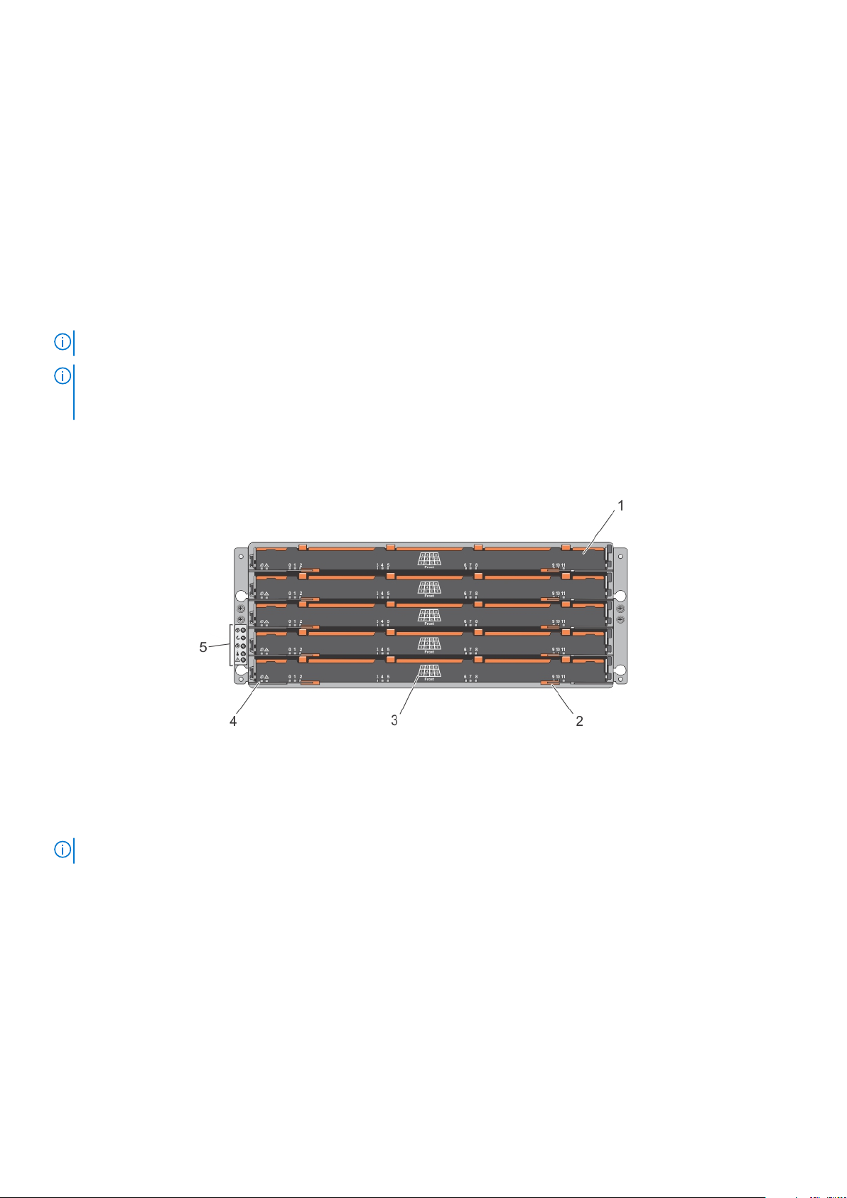
Front-panel features
Figure 1. Front-panel features
drawer (5) 2. drawer release latch (2 per drawer)
1.
3. physical disk slot numbering 4. drawer indicator LEDs
5. front-panel indicators
NOTE: The drawers are numbered from 0 to 4, with Drawer 0 being the top drawer.
6 About your system
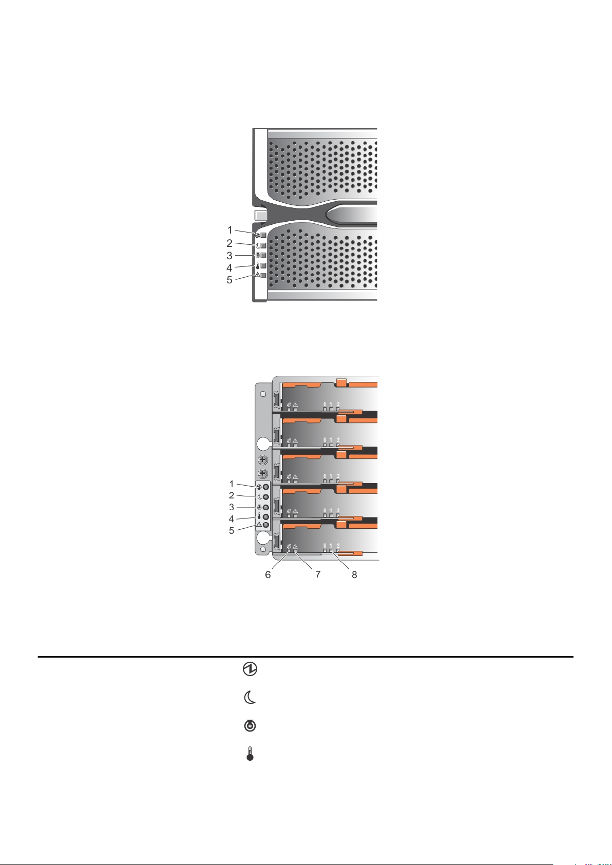
Front-panel indicators
Figure 2. Front-bezel indicators
Figure 3. Front-panel indicators
Table 1. Front-panel indicators
Item Indicator Icon Description
1 Power-on indicator The power-on indicator lights green when at least one power
supply module is supplying power to the storage enclosure.
2 Standby power indicator The standby power indicator lights green when the system is
in standby mode and the main power is off.
3 System identification indicator The system identification indicator lights white and helps
locate a particular enclosure within a rack.
4 Over temperature indicator The over temperature indicator lights amber when the
temperature of the system has reached an unsafe condition.
About your system 7
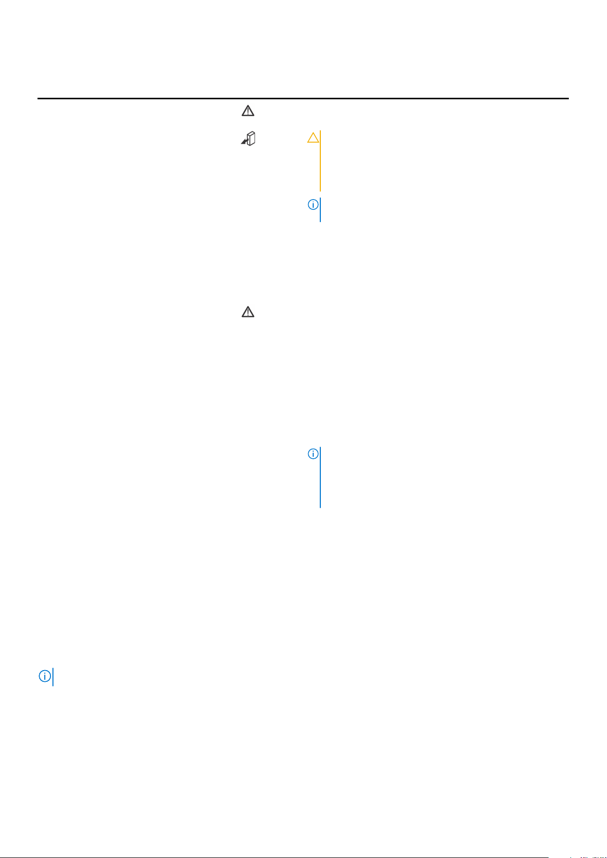
Table 1. Front-panel indicators (continued)
Item Indicator Icon Description
5 Service action required
indicator (system)
6 Service action allowed
indicator (system)
7 Service action required
indicator (drawer)
The Service action required indicator lights amber when there
is a fault in one of the components in the system.
CAUTION: Remove the physical disk drawer from the
system only if the Service action allowed indicator
lights blue. Removing the physical disk drawer from
the system when the Service action allowed indicator
is off may damage the system.
NOTE: The Service action allowed indicator LED is not
used in server attached configurations.
Blue Indicates that you can safely remove
the physical disk drawer from the
system.
Off Indicates that you cannot remove the
physical disk drawer from the system.
Amber Indicates that the cable is attached and
at least one lane has a link up status,
but at least one lane has a link down
status.
Off Indicates that:
● No cable is attached.
● A cable is attached, and all lanes
have a link up status.
● A cable is attached, and all lanes
have a link down status.
8 Drive activity indicator
NOTE: The associated physical disk is indicated by a
number (0 to 11) that is displayed above the drive activity
indicator. For example, for physical disk 2 on the physical
disk drawer, the drive activity indicator has 2 displayed
above the drive activity indicator.
Green Indicates that power is on and the
physical disk is operating normally.
Blinks green Indicates I/O activity for that physical
disk.
Off Indicates that there is no power
reaching the drive or a drive is not
installed.
Back-panel features
NOTE: The following illustration displays the Dell EMC PowerVault MD3460 storage enclosure.
8 About your system
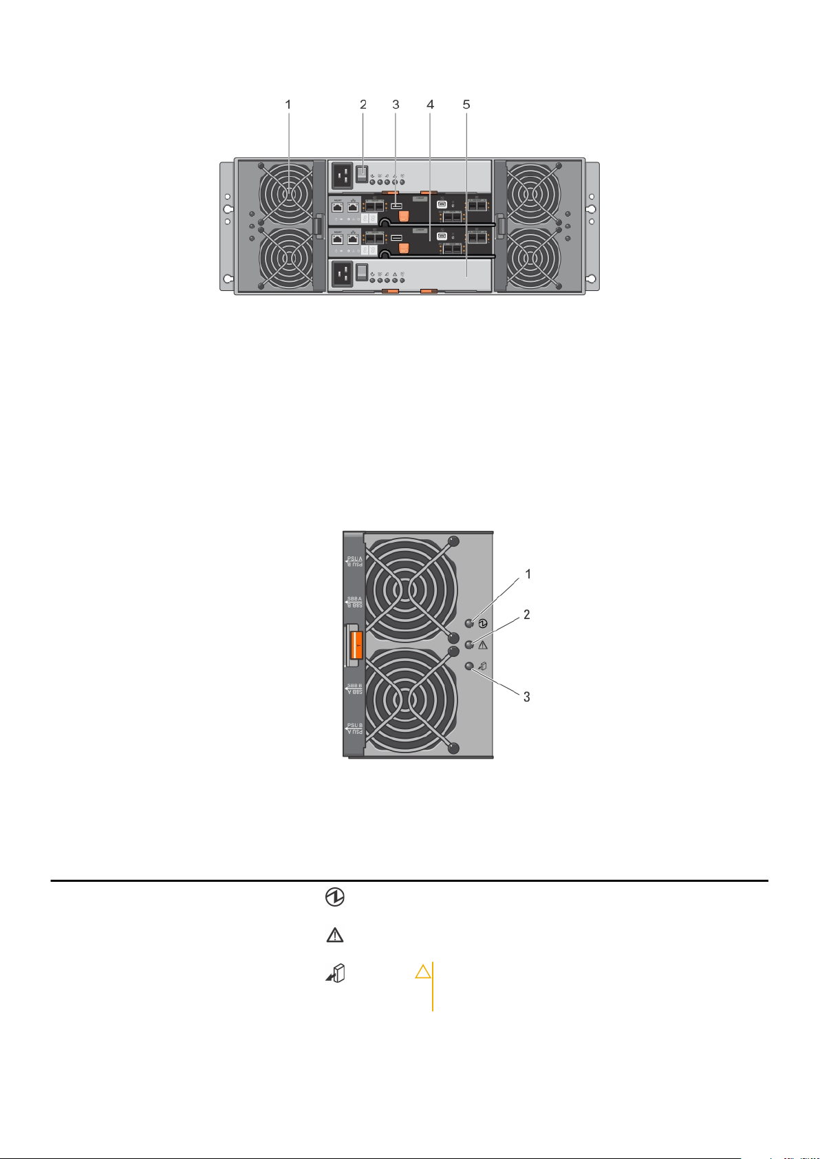
Figure 4. Back-panel features
1. cooling fan module (2) 2. power supply switch (2)
3. USB port 4. raid controller module (2)
5. power supply module (2)
Cooling fan module LED indicator codes
Figure 5. Cooling fan module indicators
Table 2. Cooling fan module LED indicator codes
Item Indicator Icon Description
1 Power indicator The power indicator lights green when power to the cooling
fan module is available.
2 Service action required
indicator
3 Service action allowed
indicator
The Service action required indicator lights amber when there
is a fault in the cooling fan module.
CAUTION: Remove the cooling fan module from the
system only if the Service action allowed indicator
lights blue. Removing the cooling fan module from
About your system 9
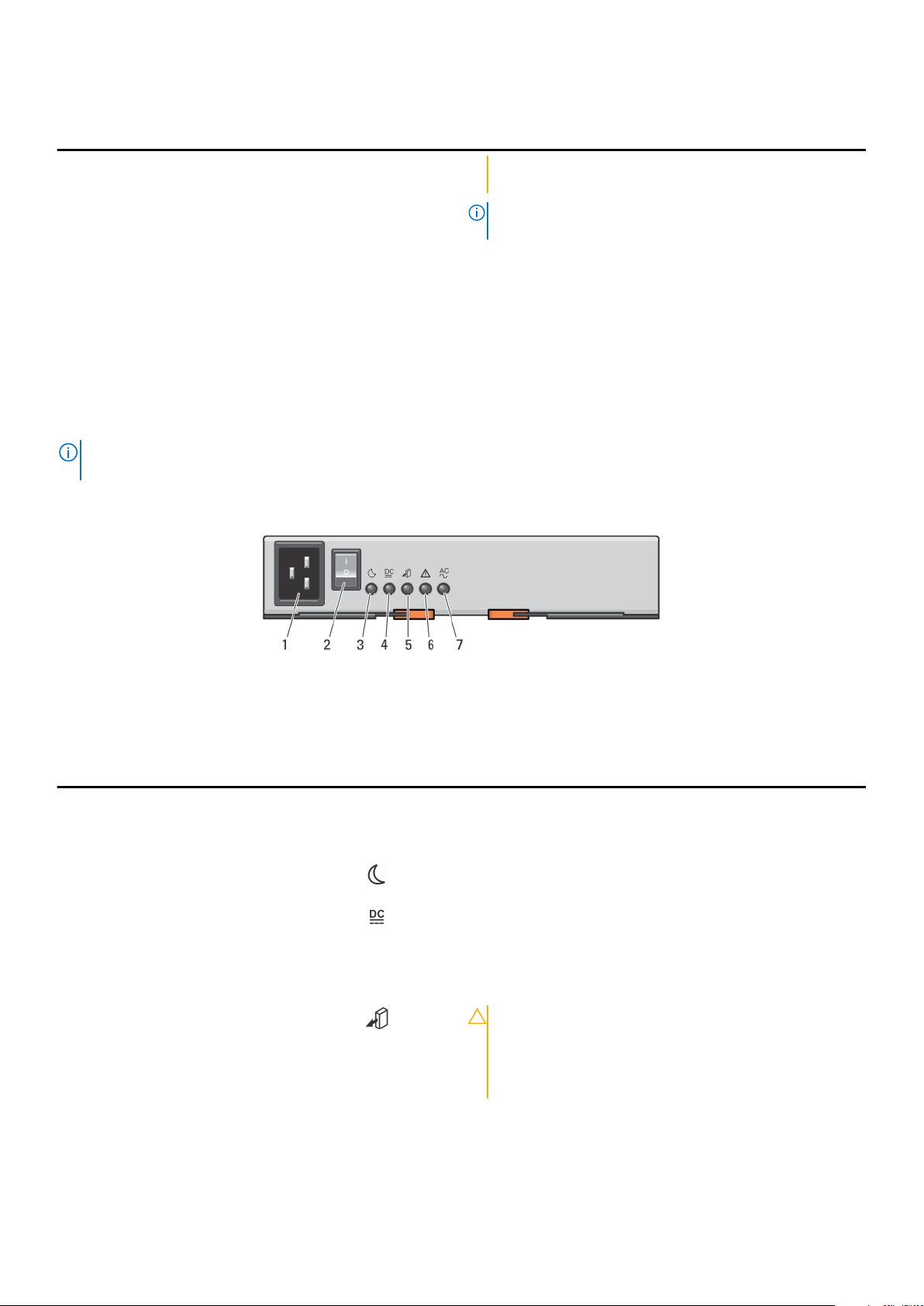
Table 2. Cooling fan module LED indicator codes (continued)
Item Indicator Icon Description
the system when the Service action allowed indicator
is off may damage the system.
NOTE: The Service action allowed indicator LED is not
used in server attached configurations.
Blue Indicates that you can safely remove
the cooling fan module from the
system.
Off Indicates that you cannot remove the
cooling fan module from the system.
Power supply module features and indicators
NOTE: Your storage array is shipped with two IEC C19 to C20 jumper cords. Connect the C19 plug to the array's power
supplies and the C20 plug to the power distribution unit (PDU) in the rack cabinet.
Figure 6. Power supply module features and status indicators
Table 3. Power supply module features and indicators
Item Indicator or Connector Icon Description
1 Power connector Connect the external power supply source to this connector.
2 Power switch The power switch controls the power supply output to the
system.
3 Standby power indicator The standby power indicator lights green when the system is
in standby mode and the main power is off.
4 DC power indicator
5 Service action allowed
indicator
Green Indicates that DC output voltage is
within the limit.
Off Indicates that DC output voltage is not
within the limit.
CAUTION: Remove the power supply module from
the system only if the service action allowed
indicator lights blue. Removing the power supply
module from the system when the service action
allowed indicator is off may damage the system.
Blue Indicates that you can safely remove
the power supply module from the
system.
10 About your system
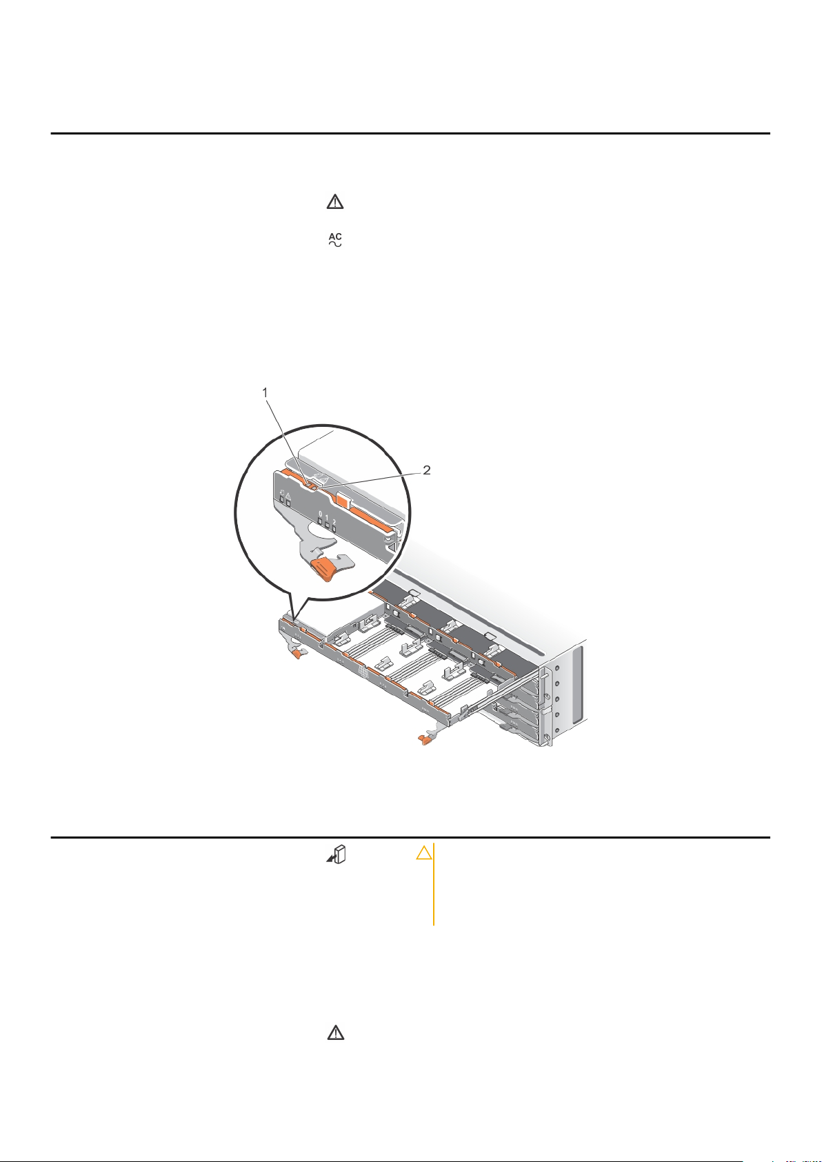
Table 3. Power supply module features and indicators (continued)
Item Indicator or Connector Icon Description
Off Indicates that you cannot remove the
power supply module from the system.
6 Service action required
indicator
7 AC power indicator
The service action required indicator lights amber when there
is a fault in the power supply module.
Physical-disk LED indicators
Green Indicates that AC output voltage is
within the limit.
Off Indicates that AC output voltage is not
within the limit.
Figure 7. Physical-disk LED indicators
Table 4. physical-disk LED indicators
Item Indicator Icon Description
1 Service action allowed
indicator
2 Service action required
indicator
CAUTION: Remove the physical disk from the system
only if the service action allowed indicator lights
blue. Removing the physical disk from the system
when the service action allowed indicator is off may
damage the system.
Blue Indicates that you can safely remove
Off Indicates that you cannot remove the
The service action required indicator lights amber when there
is a fault in the physical disk.
the physical disk from the system.
physical disk from the system.
About your system 11
Controller modules
RAID controller modules
RAID controller modules provide high-performance, advanced virtual disk configuration, and fault-tolerant disk subsystem
management. Each RAID controller module contains 4 GB of mirrored cache for high availability and is protected by a battery
powered cache offload mechanism.
NOTE: 8 GB mirrored cache is an optional feature.
RAID controller modules provide the following data path and enclosure management functions:
● Monitoring and controlling enclosure environment elements (temperature, fans, power supplies, and enclosure LEDs)
● Controlling access to the physical disks
● Communicating enclosure attributes and states to the host server and management station
Topics:
• MD3460 SAS RAID controller module features and indicators
• Expansion controller modules
• RAID controller module—additional features
• Storage array thermal shutdown
• System password reset
2
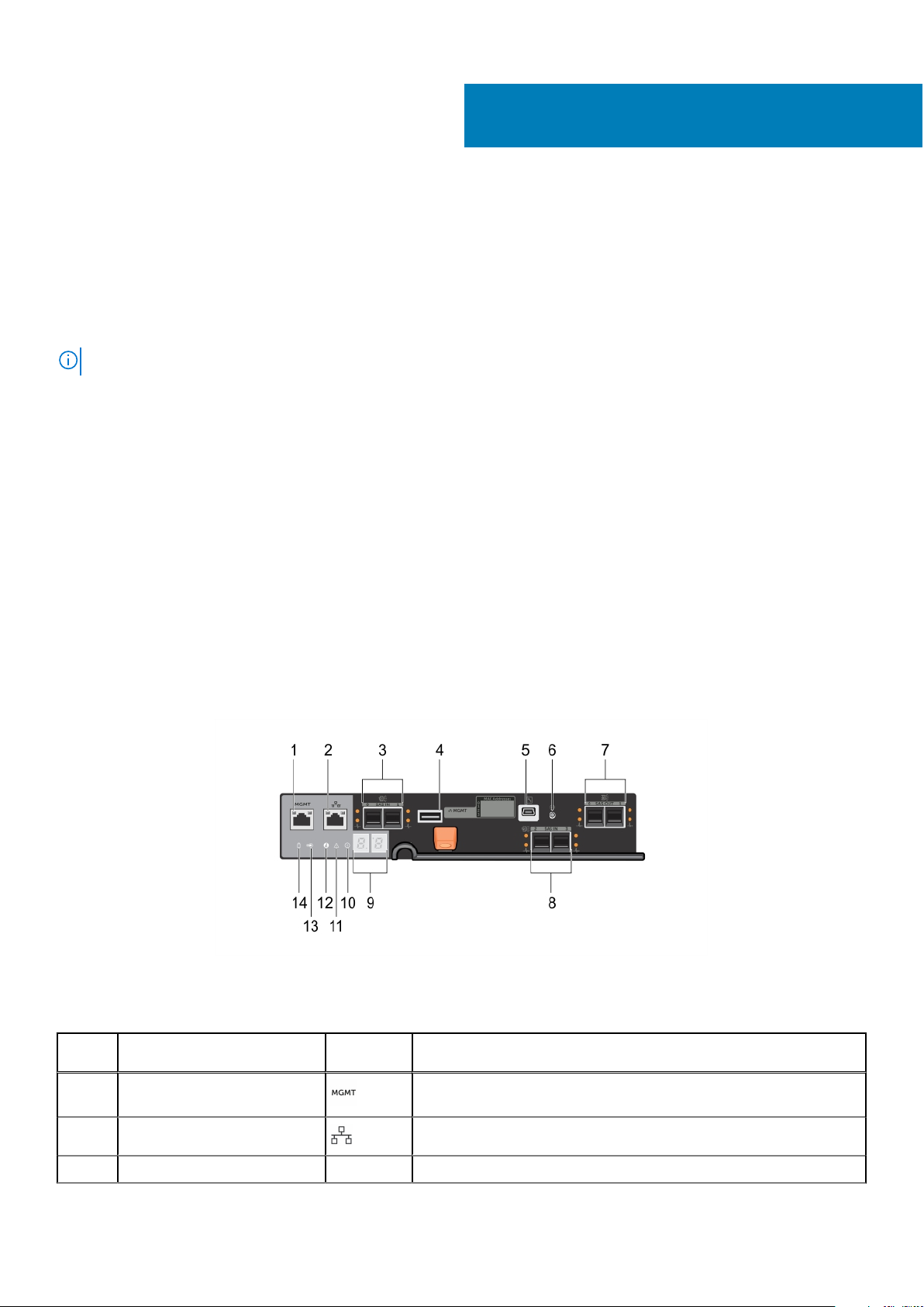
MD3460 SAS RAID controller module features and indicators
Figure 8. MD3460 SAS RAID controller module features and indicators
Table 5. MD3460 SAS RAID controller module features and indicators
Item Indicator, Button, or
Connector
1 Ethernet management port Provides a 100/1000 Mbps Ethernet connection for out-of-band
Icon Description
management of the enclosure.
2 Reserved Ethernet port Reserved port.
3 12 Gbps SAS IN port (2) Provides host-to-controller SAS connection.
12 Controller modules
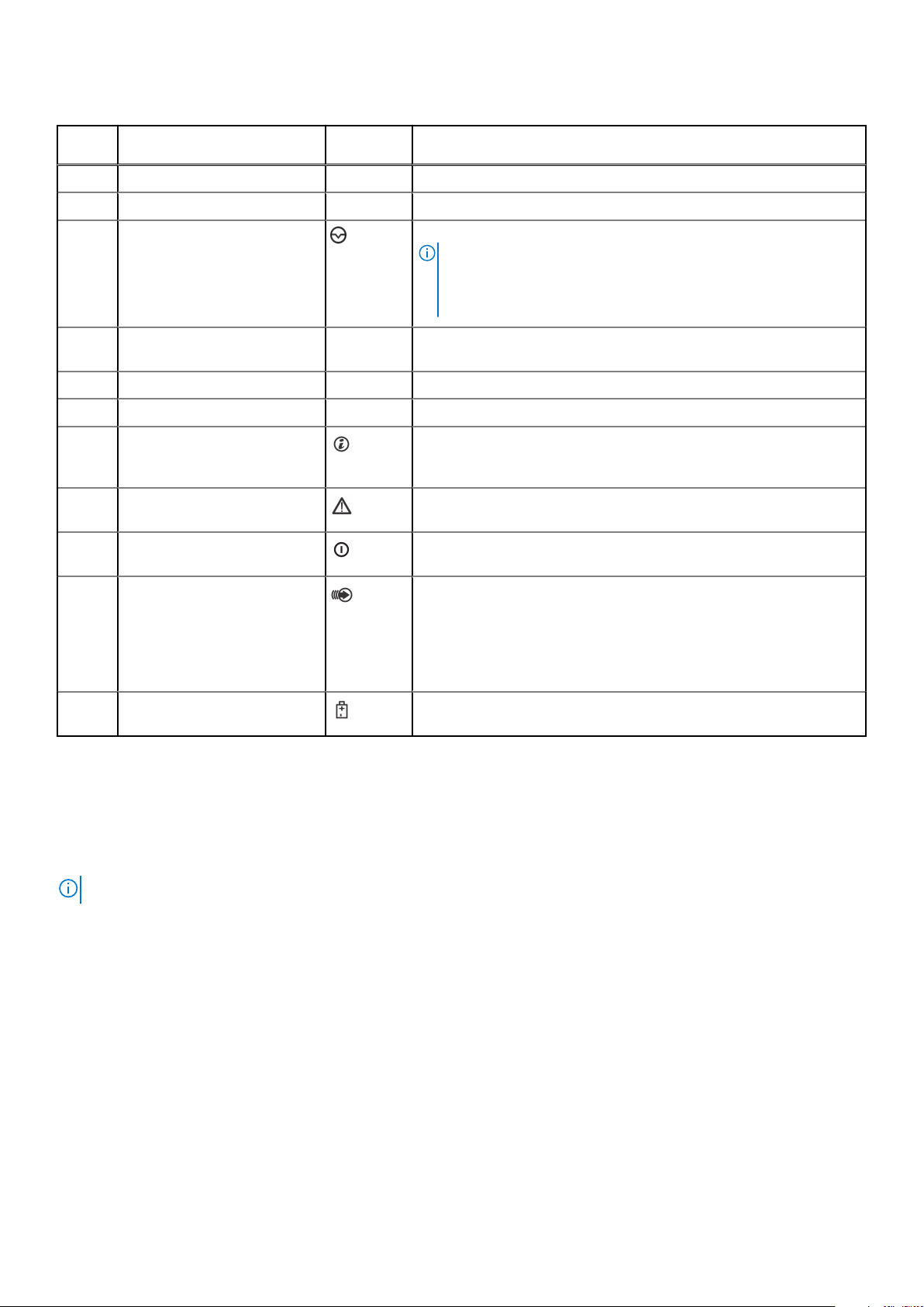
Table 5. MD3460 SAS RAID controller module features and indicators (continued)
Item Indicator, Button, or
Connector
4 USB port Reserved port.
5 Mini USB port Dell EMC support only.
6 Password reset switch Pressing this switch resets the password.
7 SAS expansion port (2) Provides SAS OUT connection for cabling to a daisy chained
8 12 Gbps SAS IN port (2) Provides host-to-controller SAS connection.
9 7 segment display sequence Displays status or error codes for the storage array.
10 System identification indicator The system identification indicator blinks blue when system
11 Controller fault indicator The controller fault indicator lights amber when controller fault is
12 Controller power indicator The controller power indicator lights green when controller power is
Icon Description
NOTE: The password reset switch is not available if your system
was shipped after September 2015. The password reset switch
functionality was disabled starting from controller firmware
08.20.09.60 and later versions.
expansion enclosure. Port 0 expansion port is recommended.
identification switch push-button on the enclosure front panel is
pressed.
detected.
on.
13 Cache active or cache offload
indicator
14 Battery fault indicator The battery fault indicator lights amber when battery backup unit or
The cache active or cache offload indicator lights green when onboard controller memory contains data.
If AC power fails, this LED changes to indicate cache offload status.
If the password reset function has successfully changed the
password, this LED flashes on and off briefly.
battery has failed.
Expansion controller modules
Use the expansion controller modules to expand the storage capacity up to a maximum of 120 disks (180 disks with premium
feature kit), by daisy-chaining your storage enclosure with one MD3060e expansion enclosure without the premium feature kit
and up to two MD3060e expansion enclosures with the premium feature kit.
NOTE: Hot-plug of MD3060e expansion enclosure is not supported.
Controller modules 13
 Loading...