

Page 1

Dell™ PowerVault™
Network Attached Storage
(NAS) Solution
iSCSI Deployment Guide
www.dell.com | support.dell.com
Page 2

Notes, Cautions, and Warnings
NOTE: A NOTE indicates important information that helps you make better use of
your computer.
CAUTION: A CAUTION indicates potential damage to hardware or loss of data if
instructions are not followed.
WARNING: A WARNING indicates a potential for property damage, personal
injury, or death.
____________________
Information in this document is subject to change without notice.
© 2009 Dell Inc. All rights reserved.
Reproduction of these materials in any manner whatsoever without the written permission of Dell Inc.
is strictly forbidden.
Trademarks used in this text: Dell, the DELL logo, and PowerVault are trademarks of Dell Inc.;
Microsoft, Windows, and Windows Server are either trademarks or registered trademarks of Microsoft
Corporation in the United States and/or other countries.
Other trademarks and trade names may be used in this document to refer to either the entities claiming
the marks and names or their products. Dell Inc. disclaims any proprietary interest in trademarks and
trade names other than its own.
May 2009 Rev. A00
Page 3

Contents
1 Introduction . . . . . . . . . . . . . . . . . . . . . . . . 7
Terms and Definitions . . . . . . . . . . . . . . . . . . . 8
Before Setting Up the PowerVault Storage Solution as
an iSCSI Target
2 Setup Steps for Initiator-Target
Connection
PowerVault Storage System
. . . . . . . . . . . . . . . . . . . . . . . . . 8
iSCSI
. . . . . . . . . . . . . . . . . . . . . . . . . . 8
iSNS
. . . . . . . . . . . . . . . . . . . . . . . 9
. . . . . . . . . . . . . 8
Best Practices for Setting Up the iSCSI Storage
Area Network
. . . . . . . . . . . . . . . . . . . . . 9
. . . . . . . . . . . . . . . . . . . . . . . 13
Pre-Requisites . . . . . . . . . . . . . . . . . . . 13
Method 1 (Discovery Using Target Portals)
Configuring the Initiator (Host)
. . . . . . . 13
. . . . . . . . . . . 14
Configuring iSCSI Connection With the PowerVault
NAS Storage System
Creating the Target
Creating a Virtual Disk
. . . . . . . . . . . . . . . . 14
. . . . . . . . . . . . . . . . . 14
. . . . . . . . . . . . . . . 16
Log on - Configuring the Initiator-Target Connection
From Initiator (Host)
Method 2 (Discovery Using iSNS Server)
Pre-Requisites
. . . . . . . . . . . . . . . . 17
. . . . . . . . 18
. . . . . . . . . . . . . . . . . . . 18
Configuring Settings From the Initiator
. . . . . . 18
Contents 3
Page 4

3 Target Details . . . . . . . . . . . . . . . . . . . . 21
Setting Up Target IP Addresses in the PowerVault™
NAS Storage Solution
Configuring Microsoft
Configuring iSCSI LUNs
Multiple Sessions
iSCSI Snapshots
. . . . . . . . . . . . . . . . . . 21
®
iSCSI Software Targets . . 21
. . . . . . . . . . . . . . . 26
. . . . . . . . . . . . . . . . . . 27
. . . . . . . . . . . . . . . . . . 27
Disconnecting/Cleaning Up iSCSI Devices
From Initiator
From Target
. . . . . . . . . . . . . . . . . . . . 32
. . . . . . . . . . . . . . . . . . . . . 32
. . . . . . . 32
4 Configuring Secured iSCSI Connections
Using Challenge-Handshake
Authentication Protocol
CHAP vs IPSec . . . . . . . . . . . . . . . . . . . . . . 36
One-Way CHAP Authentication
iSCSI Target Settings
iSCSI Initiator Settings
Mutual CHAP Authentication
Initiator Settings
Target Settings
Initiator Settings Continued
. . . . . . . . . . . . . . . . . . 37
. . . . . . . . . . . . . . . . . . . 38
. . . . . . . . . . . . . 35
. . . . . . . . . . . . . 36
. . . . . . . . . . . . . . . . 36
. . . . . . . . . . . . . . . 37
. . . . . . . . . . . . . . 37
. . . . . . . . . . . . . 38
A Appendix . . . . . . . . . . . . . . . . . . . . . . . . 39
4 Contents
Initiator Details. . . . . . . . . . . . . . . . . . . . . . 39
General Tab
Discovery Tab
Targets Tab
. . . . . . . . . . . . . . . . . . . . . 39
. . . . . . . . . . . . . . . . . . . . 40
. . . . . . . . . . . . . . . . . . . . . 42
Page 5

Advanced Configuration Details . . . . . . . . . . . . 45
Enabling Multi-Path on the Initiator
Using the Advanced Option
. . . . . . . . 45
. . . . . . . . . . . . 46
Verifying the Properties of the Targets that
are Connected
. . . . . . . . . . . . . . . . . . . 46
Installing and Configuring iSNS Server
Configuring the iSNS Server
. . . . . . . . . 48
. . . . . . . . . . . . 49
Best Practices for Efficient Storage Management
Storage Manager for SANs
LUN Management for iSCSI Subsystems
Known Issues
. . . . . . . . . . . . . . . . . . . . . . 51
. . . . . . . . . . . . 50
. . . . . . 50
. . . 50
Contents 5
Page 6

6 Contents
Page 7

Introduction
This document provides information about configuring the
Internet Small Computer System Interface (iSCSI) Software Target on the
Dell™ PowerVault™ storage system as a block storage device.
iSCSI is a useful and relatively inexpensive way to provide storage for new
applications or to provide a network pool of storage for existing applications.
Dell and its storage partners provide a variety of storage solutions that can be
implemented easily. This document allows administrators and IT managers to
explore iSCSI technology and see actual deployment examples.
The following topics are discussed in the document:
• Quick install steps—Provides instructions about creating an iSCSI Target
and establishing connection with a Microsoft
• End-to-end iSCSI configuration:
– Detailed instructions on installing and configuring the Microsoft
iSCSI Initiator software and the Microsoft iSCSI Software Target
– Configuring the Initiator-Target connections
• Setting up secure iSCSI connections
• Microsoft iSNS server and other advanced configuration details
NOTE: In this document the iSCSI Initiator is referred to as the Initiator and the
iSCSI Software Target is referred to as the Target.
®
iSCSI Initiator
Introduction 7
Page 8

Terms and Definitions
The following sections describe the terms used in this document.
PowerVault Storage System
Throughout this document, the term PowerVault storage system refers to the
individual storage unit. The term PowerVault storage solution refers to the
configuration of the server separately or together with the storage arrays.
iSCSI
iSCSI is a standard that carries SCSI commands through Transfer Control
Protocol/Internet Protocol (TCP/IP)—a protocol that enables transport of
block data over IP networks, without the need for a specialized network
infrastructure, such as Fibre Channel.
In the context of system storage, iSCSI enables any client/machine (Initiator)
on an IP network to contact a remote dedicated server (Target) and perform
block I/O on it just as it would perform on a local hard disk.
iSNS
Microsoft iSCSI Internet Storage Name Service (iSNS) is a service that
processes iSNS registrations, deregistrations, and queries through TCP/IP from
iSNS clients and also maintains a database of these registrations (similar to a
DNS server). A common use for Microsoft iSNS server is to allow iSNS clients
(Initiators and Targets) to register themselves and to query for other registered
iSNS clients. Registrations and queries are transacted remotely over TCP/IP.
You can download and install the iSNS server from the Microsoft Support
website at support.microsoft.com on a separate server that does not have
Microsoft iSCSI Initiator or Target installed.
NOTE: For details about installing and configuring the iSNS server, see "Appendix"
on page 39.
8 Introduction
Page 9

Before Setting Up the PowerVault Storage Solution as an iSCSI Target
Before you set up your storage solution as an iSCSI Target, read this section
completely. You must consider features such as Ethernet settings and security
settings for iSCSI Targets.
Best Practices for Setting Up the iSCSI Storage Area Network
Table 1-1 provides information about configuring NICs (on Target) in
different models of iSCSI networks.
• You can configure redundant paths on Initiator (hosts). Microsoft
Multipath I/O (MPIO) is supported with Initiator version of 2.06 or later.
• You require two dedicated iSCSI NICs on the Target and Initiator for
efficient MPIO connection in the PowerVault storage solution.
• iSCSI NIC teaming is not supported.
• You can configure Initiators with one or two dedicated NICs for iSCSI
based on your requirement.
NOTE: Table 1-1 provides information about the iSCSI Target NIC
configuration. The optimal connection information is also provided as options.
You can configure the iSCSI NICs according to your network requirements.
Table 1-1. Using a Single PowerVault Storage Solution as a Target
Number of NICs Details Refer to Figure
4 NIC-1 and NIC-2 - Teamed NICs for public
network
NIC-3 - iSCSI dedicated traffic (subnet A)
NIC-4 - iSCSI dedicated traffic (subnet B)
3
NOTE: Use this
configuration if iSCSI
traffic has more
priority than file traffic.
NIC-1 - NIC for public Network
NIC-2 - iSCSI dedicated traffic (subnet A)
NIC-3 - iSCSI dedicated traffic (subnet B)
Figure 1-1
Figure 1-2
Introduction 9
Page 10

• It is a good practice to have two ports dedicated for iSCSI. Configure each
NIC (or ports if you have a multiport NIC) on a separate subnet.
• Secured iSCSI is possible with Challenge-Handshake Authentication
Protocol (CHAP). For more information about CHAP settings, see
"Configuring Secured iSCSI Connections Using Challenge-Handshake
Authentication Protocol" on page 35.
Table 1-2. Worksheet
Options Host IP Target IP
iSCSI
NIC 1
NIC 2
NIC 3
NIC 4
Public
Other
iSCSI
Public
Other
iSCSI
Public
Other
iSCSI
Public
Other
NOTE: IQNs are the standard naming convention for identifying Targets and
Initiators and it is recommended that you use IQN as the identifier whenever
possible.
NOTE: It is recommended that you configure dedicated iSCSI NICs on
separate subnets and not on the public network.
10 Introduction
Page 11
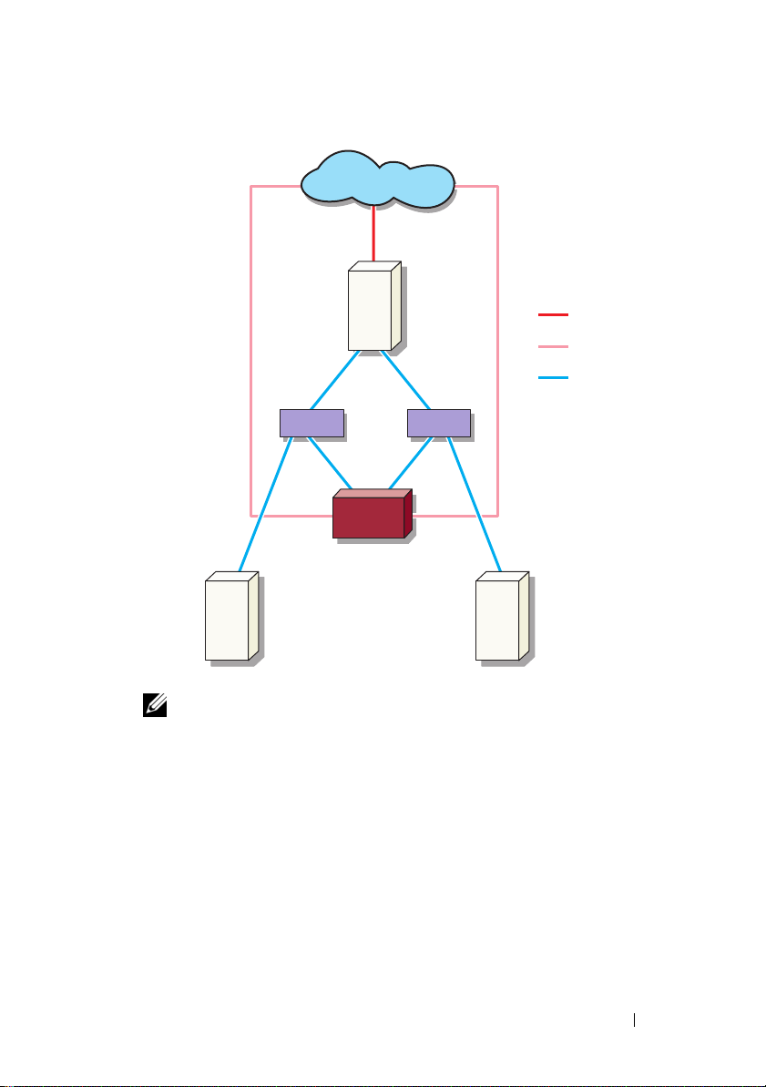
Figure 1-1. Redundant iSCSI Paths and NIC Teaming for Data Sharing With Four NICs
public network
optional iSNS
server
NOTE: For a detailed configuration of the iSCSI Target, see "Target Details" on
page 21.
host
(Initiator)
switch switch
PowerVault storage
system with NIC Teaming
for File sharing
public network
NIC Teaming
dedicated iSCSI
traffic
optional iSNS
server
Introduction 11
Page 12
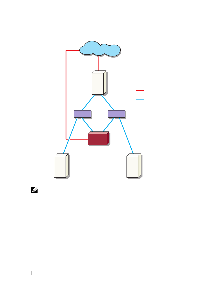
Figure 1-2. Redundant iSCSI Paths With Three NICs
public network
host (Initiator)
public network
iSCSI traffic
switch
PowerVault storage
system
optional iSNS
server
NOTE: For a detailed configuration of the iSCSI Target, see "Target Details" on
page 21.
switch
optional iSNS
server
12 Introduction
Page 13

Setup Steps for Initiator-Target Connection
This section provides step-by-step instructions to set up an iSCSI Target and
establish connection from an Initiator. It is assumed that the user is familiar
with the following:
• Operations of iSCSI protocol
• iSCSI Initiator-Target connection information
®
• Install and setup of Microsoft
Target, and Microsoft iSNS server
Pre-Requisites
Before you set up the iSCSI Target, ensure that you perform the following steps:
1
Download the latest Microsoft iSCSI Initiator software from Microsoft
support website at
2
Install MS Software iSCSI Target on your storage system from the CD
provided.
3
Configure and assign the IP addresses for iSCSI network using the
"Worksheet" on page 10.
Before configuring iSCSI Targets, ensure that you perform the following tasks:
1
Create a few LUNs and reserve storage space to create virtual disks for
iSCSI Targets.
2
Right-click
NICs for iSCSI traffic (see Figure 3-1 "Creating iSCSI Targets" on page 23).
iSCSI Target
support.microsoft.com
iSCSI Initiator, Microsoft Software iSCSI
and install the Initiator (Host).
and select
Properties
to configure dedicated iSCSI
Method 1 (Discovery Using Target Portals)
To perform Target discovery, enter the IP address of one of the NICs of the
PowerVault storage system that is configured for iSCSI traffic in the Initiator
and thereby enabling the Initiator to discover all Targets of this Target server.
Setup Steps for Initiator-Target Connection 13
Page 14

The following steps guide you through setting up an iSCSI Target and
establishing connection from an Initiator.
Configuring the Initiator (Host)
Log on from
Initiator setup Target setup
Initiator
Configure the Microsoft iSCSI Initiator with the IP address of the Target
server's information. To configure the Initiator:
1
Go to the system that has Microsoft iSCSI Initiator installed.
2
Click
Start→
Properties
3
Select
4
Add the IP address of one of the NICs on the PowerVault storage system
Programs→
→ Discovery
Add portal
Microsoft iSCSI Initiator→
iSCSI Initiator
tab.
.
that is configured for iSCSI traffic (see Figure 1-1).
5
Click OK.
Configuring iSCSI Connection With the PowerVault NAS Storage System
Initiator setup
Target setup
Creating the Target
1
From the PowerVault NAS appliance, select
Storage→
2
Select
MS Software Target
.
Microsoft iSCSI Software Target
The following options are displayed—
Snapshots
3
Select
option in the
4
Select the
5
The
Select
.
iSCSI Targets
Create iSCSI Target
and either right-click or select the
Actions
tab.
option.
Welcome to the Create iSCSI Target
Next
.
The wizard guides you through the process of Target creation.
14 Setup Steps for Initiator-Target Connection
Start→
icon.
iSCSI Targets, Devices
wizard screen is displayed.
Log on from
Initiator
Server Manager→
, and
More Actions
Page 15

6
The
Create iSCSI Target
option. Enter a
Next
click
7
Click
Browse
Name
. The
iSCSI Initiators Identifiers
and select the IQN for the host that connects to the Target.
wizard displays the
and
Description
iSCSI Target Identification
(optional) for the iSCSI Target and
screen appears.
The host is listed only if step 1 in "Configuring the Initiator (Host)" on
page 14 was completed successfully.
NOTE: You must fill the IQN identifier field. You can type the Initiator IQN
identifier or use the Browse and Advanced options in the screen to add the
IQN identifier. For more information about the Browse option, see step 8.
For more information about the Advanced option, see step 9.
8
If you choose the
Browse
option, you can select the
IQN identifier
performing the following steps:
a
Select
Browse
b
The details for iSCSI Initiator list is displayed. You can type or select
and the
Add iSCSI Initiator
screen appears.
iSCSI Initiator from the list, enter the iSCSI Initiator Name, and
select
OK
. The
Identifiers
Select
9
If you choose the
IQN identifier
screen is populated with the value entered or selected.
Next
. Go to step 10.
Advanced
field in the
iSCSI Initiators
option, you can select the
IQN identifier
performing the following steps:
a
When you choose the
screen appears and displays the
b
The
Add/Edit Identifier
IQN, DNS Domain Name, IP address
IQN identifier
c
Type in the value or choose the value through the
then select
. Choose any one of the four options.
OK
The IQN identifier is displayed in the
and the fields
Address
IQN, DNS Domain Name, IP address
are populated.
.
Advanced..
option, the
Add
option. Select
Advanced Identifiers
Add
.
appears and provides four options namely—
, and
MAC Address
Browse
to add the
option, and
Advanced Identifiers
, and
MAC
by
by
screen
d
Select the populated value and select OK.
e
In the
iSCSI Initiator Identifiers
screen, the
populated with appropriate information. Click
alternate identifiers.
Setup Steps for Initiator-Target Connection 15
IQN identifier
Advanced
to view
field is
Page 16

f
Select
Next
.
NOTE: IQNs work regardless of the DNS configuration. You can also specify the IP
address or MAC address of the Initiator regardless of DNS configuration.
The option of specifying a DNS domain name is built into the iSCSI Software Target
snap-in. While using DNS names, you must configure DNS correctly (including
forward and reverse lookup zones) and specify the fully qualified domain name
(FQDN) of the Initiator. If you are unable to connect the Target to the Initiator after
specifying the Initiator FQDN, run the nslookup InitiatorIP command on the target
server to verify if reverse lookup is enabled correctly.
If the nslookup command fails, it indicates that the DNS reverse lookup is not
configured. In such a case, reconfigure the Target to use the Initiator IQN, IP
address, or MAC address.
10
The
Completing the Create iSCSI Target
wizard appears. Click
Creating a Virtual Disk
1
Right-click the newly created Target and click
iSCSI Target
2
To create a file, choose the
. The
Create Virtual Disk
Browse
option, select a volume on the storage
array and type a file name with an extension
For example, create
storage array and
3
In the
Size
screen, choose the appropriate size from
free space
4
The
and click
Description
required and click
5
In the
Add
screen, select the Target name and click
6
The
Completing the Create Virtual Disk
Z:\vol1.vhd
vol1.vhd
Next
, where Z is the mounted volume from
is the filename. Select
.
screen may appear. Enter the virtual disk description, if
Next
.
Create Virtual Disk for
wizard appears. Select
.vhd
.
Next
.
Currently available
Next
.
wizard appears. Click
Next
Finish
Finish
.
.
.
CAUTION: If multiple hosts access the same Target, data corruption may occur.
For more information, see "Enabling Multi-Path on the Initiator" on page 45.
NOTE: You can create multiple VHDs on the same volume.
16 Setup Steps for Initiator-Target Connection
Page 17

Log on - Configuring the Initiator-Target Connection From Initiator (Host)
Lo
Initiator setup Target setup
1
From the iSCSI Initiator (host), click
iSCSI Initiator
2
Refresh the screen. The PowerVault storage system Target device that you
→ iSCSI Initiator Properties→
Start→
Log on from
Initiator
Programs→
Targets
tab.
Microsoft
created in "Configuring iSCSI Connection With the PowerVault NAS
Storage System" on page 14 is displayed in the IQN name format.
3
In the
Log On to Target window
Enable multi-path
4
Click
Advanced
options.
. In the
Advanced Settings
, select
Logon, Automatically restore
window, select
General
select the following options from drop-down menu:
–
Local adapter
–
Source IP
Target Portal
–
5
In the
Advanced Settings
6
In the
Log On to Target
Ta r g et s
The
7
To accomplish Multipathing, you can use Microsoft MPIO to establish
—Microsoft iSCSI Initiator
—One of the host I/P addresses that is used for iSCSI traffic
—PowerVault storage solution's iSCSI IP address
window, click OK.
window, click OK.
tab displays the status of the Target as
Connected
.
multiple sessions from host to the same Target device. To establish
multiple sessions:
a
Go to the
b
Repeat step 1 to step 5.
c
Click
Ta r g et s
tab and select the Target that is
Advanced Settings
. In the
Target Portal
Connected
address, choose the
redundant host IP address and the IP address of the PowerVault storage
solution.
and
tab and
.
NOTE: During the iSCSI Initiator software installation, Microsoft MPIO is
already selected. MPIO is supported with Initiator version of 2.06 or later. You
require two dedicated iSCSI NICs in the Target and Initiator for efficient MPIO
connection. Multiple connections per session (MC/S) is not supported on the
PowerVault storage solution.
Setup Steps for Initiator-Target Connection 17
Page 18

8
To initialize and configure the iSCSI device as local drive and perform iSCSI
I/O operations, select
CAUTION: If multiple hosts access the same Target, data corruption may occur.
For more information, see "Enabling Multi-Path on the Initiator" on page 45.
Computer Management→
Disk Management
option.
Method 2 (Discovery Using iSNS Server)
This section describes the procedure for iSCSI Target discovery using the iSNS
server. For more information about the iSNS server, see "Appendix" on page 39.
Pre-Requisites
Before you perform iSCSI Target discovery, perform the following steps:
1
Identify a system to serve as an iSNS server.
2
Ensure that the Initiator and the Target are on the same network as the
iSNS server (see Figure 1-1 and Figure 1-2).
3
Download the Microsoft iSCSI Initiator software from Microsoft Support
website at
4
Download the Microsoft iSNS server software from Microsoft Support
website at
support.microsoft.com
support.microsoft.com
client/server running Microsoft
NOTE: Do not install the iSNS server software on Initiator (host) or Target
(PowerVault storage solution). Install the software on a separate Client/Server
running Windows operating system.
5
Turn on the PowerVault storage system and create one or more volumes on
the storage array for creating virtual disks for iSCSI Targets.
and install the Initiator (Host).
and install the software on a
®
Windows® operating system.
Configuring Settings From the Initiator
Initiator setup
1
Configure the Microsoft iSCSI Initiator with iSNS server's information.
Start→
Go to
Initiator
2
Add the IP address of the iSNS server and click OK (see Figure 1-1 and
Programs→
→ Discovery tab→
Target setup
Administrative Tools→ Microsoft iSCSI
Add iSNS
.
Figure 1-2).
18 Setup Steps for Initiator-Target Connection
Log on from
Initiator
Page 19

Setting Up the Target (PowerVault Storage System)
Initiator setup
1
From the PowerVault storage system, go to
Target setup
Storage→ Microsoft iSCSI Software Target
The
PowerVault Server Manager Management Console
2
Select
Microsoft iSCSI Software Target
snap-in and right-click on
3
In the
Properties
window, select the
Properties
which is located in the storage
.
iSNS
Log on from
Initiator
Start→
Server Manager
→
.
appears.
tab and add the iSNS server
information (DNS Name or IP address).
NOTE: It is recommended that only NICs for iSCSI network are checked.
4
To create a Target, follow the instructions in "Configuring iSCSI
Connection With the PowerVault NAS Storage System" on page 14.
NOTE: During step 7 of Configuring the Target, use the Browse option to
ensure that the iSCSI Initiator Identifier screen displays all Initiators that are
registered with the iSNS server.
5
To create a virtual disk, follow the instructions in "Creating a Virtual Disk"
on page 16.
Log on - Configuring the Initiator-Target Connection From Initiator (Host)
For information about configuring the Initiator-Target connection, see "Log on Configuring the Initiator-Target Connection From Initiator (Host)" on page 17.
Setup Steps for Initiator-Target Connection 19
Page 20

20 Setup Steps for Initiator-Target Connection
Page 21

Target Details
This section describes the end-to-end iSCSI setup, including settings for the
iSCSI Initiator, Target, and establishing connections.
Setting Up Target IP Addresses in the PowerVault™ NAS Storage Solution
Based on your system configuration (with one or two dedicated iSCSI NICs)
assign IP addresses to the iSCSI NICs. Use the IP address that you assigned to
the iSCSI NIC(s) in the Target Portals tab of the Initiator for discovery.
Configuring Microsoft® iSCSI Software Targets
Before configuring iSCSI Targets, you must create a few LUNs and reserve
storage space to create virtual disks for iSCSI Targets. The following section
provides step-by-step instructions to create storage space.
1
Configuring network settings on the iSCSI Target device—The
PowerVault NAS storage solution is configured to use DHCP for network
settings by default. The PowerVault NAS storage system is designed for
multi-path operations and is equipped with two RJ45 Ethernet connectors.
You can add an optional additional NIC. The
Configuration tasks
NOTE: It is recommended that you configure dedicated iSCSI NICs on
separate subnets and not on the public network.
window displays the basic settings.
PowerVault NAS
NOTE: It is important at this point to note that the storage solution LUN size
should not be confused with the size of the iSCSI Target. The iSCSI Target is
configured in a later step and is associated with the storage needed for a
particular application on the host server. It is recommended that the LUN size
on the storage hardware be as large as reasonably possible to allow the
storage subsystem to optimize the use of the physical disks underlying the
LUN that is created. In this case, as shown below, we are choosing to create
one LUN at the maximum size available for this hardware. This iSCSI LUN
cannot accommodate the iSCSI Targets that are created later, based on the
needs of the host application.
Target Details 21
Page 22

2
Preparing LUNs for use—The PowerVault NAS storage solution runs on a
Microsoft Windows
®
operating system based platform. The steps to
prepare LUNs for use, such as assigning a drive letter for the internal server,
providing a volume name, and so on are to Windows operating system
setup. The setup wizard prompts for the required information and then
provides a summary screen before performing the necessary tasks to
provision the storage.
The LUN is now created and ready for use. Step 3 creates iSCSI Targets
and associates the iSCSI Targets with the newly-created LUN.
3
Configuring NICs for iSCSI traffic in the PowerVault storage solution—
You must first configure dedicated iSCSI NICs for iSCSI traffic and then
create iSCSI Targets.
NOTE: Create iSCSI Targets only after configuring the Discovery tab in the
iSCSI Initiator
To configure dedicated iSCSI NICs:
a
Go to
PowerVault NAS Management Console→ iSCSI Target.
b
Right-click the iSCSI software Target and select
c
In the
Microsoft iSCSI Software Target Properties
Network
tab. All the NICs on the PowerVault NAS storage solution
Properties
.
window, go to the
are listed.
d
Click
Edit
and uncheck public and private network IP address from
the list. Unchecking public and private network IP addresses from the
list ensures that only the dedicated iSCSI NICs are configured
for iSCSI traffic.
e
If you have an iSNS server configured in your network, go to
and add the iSNS server IP address. Click
OK.
iSNS
tab
22 Target Details
Page 23

4
Creating iSCSI Targets—To create an iSCSI Target:
Figure 3-1. Creating iSCSI Targets
a
In the
PowerVault NAS Management Console
Targets
on the left pane to launch the
Welcome to the Create iSCSI Target Wizard
The
b
Click
Next
.
c
iSCSI Target identification
The
Enter the
Target name
and
screen is displayed.
Description
option to view and choose the servers/clients in the network.
The
iSCSI initiators identifiers
screen is displayed. You must
associate each iSCSI Target with an iSCSI Initiator. The iSCSI
Initiator is the host that requests access to the storage that is
represented by the iSCSI Target name.
d
In the
iSCSI initiators identifiers
screen, enter the iSCSI Qualified
Name (IQN) of the iSCSI Initiator. You can manually enter the IQN
or use the
Browse
option and choose the iSCSI Initiator from the list.
You can also identify the iSCSI Initiator by using the
option. When you click
appears. In the
Advanced Identifier
Advanced
, the
Identifier type and the specific identifying information.
, right-click
iSCSI
Create iSCSI Target Wizard
screen is displayed.
. You can use the
Browse
Advanced
Advanced Identifiers
screen, click
Add
, and enter the
.
screen
Target Details 23
Page 24

•Go to
Advanced Identifier→
Identifier Type
Add→
Add/Edit Identifier→
and select either IQN, DNS Domain Name, IP
address, or MAC Address to add the Initiator identifier. Figure A-5
uses the IP address to identify the iSCSI Initiator. You can use the
Browse
option to choose the value from the list of available
Targets.
NOTE: It is recommended that you use IQN as the Identifier.
The
PowerVault NAS Management Console
newly-created iSCSI Target. The
PowerVault NAS Management Console
now displays the
also displays the devices available for the iSCSI Targets. The storage that
are used by the iSCSI Initiators (application hosts) are defined in a later
step when the virtual disks are created.
5
Creating and assigning virtual disks to the Target—You must create virtual
disks on the iSCSI Targets for Microsoft-based iSCSI Target solutions.
The virtual disks represent the storage volumes that the iSCSI Initiators
use. The maximum capacity represented by all the virtual disks on a given
iSCSI Target on a Microsoft-based iSCSI Target solution is 16 terabytes
(16 TB) per Target.
The following procedure describes how to create a virtual disk. In this
example, a 100 GB virtual disk and a 200 GB virtual disk are created on the
iSCSI Target. The iSCSI Initiators identify these two virtual disks as
volumes over the TCP/IP network.
a
Right-click on the Target name to launch the
b
Click
Next
. The
File
screen appears.
Create Virtual Disk Wizard
Create the virtual disk on the internal disk volume (the RAID volumes
available from the attached storage array) that is available to the
iSCSI Target.
.
NOTE: In the File screen, use the Browse option to choose the internal disk
volume using browse and enter a name for virtual disk file with a .vhd extension.
Click
c
Next
The size of the virtual disk depends on the needs of the application on
the host server.
24 Target Details
. The
Size
screen is displayed.
Page 25

d
Choose the size for the virtual disk and click
Next
. For this example,
we choose a size of 100 GB from the available 501 GB on this volume.
The
Description
e
The
Description
screen appears.
field is optional. However, enter a description for
better management.
f
Click
Next
. The
Access
screen appears.
g
Click
Add
and enter the iSCSI Target information.
You must associate the virtual disk with an iSCSI Target for the
application host to use the virtual disk as an iSCSI storage volume.
h
Click Next. The
Completing the Create Virtual Disk Wizard
appears
indicating the successful completion of the virtual disk creation.
i
Repeat step a through step h to create an additional virtual disk.
After configuring the virtual disks, the
Console
The
displays the virtual disks associated with the iSCSI Target.
iSCSI Target device
view displays the total volume size and the free
PowerVault NAS Management
space on the device (RAID volume) that is available for iSCSI Targets.
The iSCSI Target configuration is now complete.
Configuring Devices
You can perform all operations related to virtual disks (devices) using the
following options in PowerVault NAS Management Console:
• Create/Delete Virtual Disk—Virtual disks are represented with a
.vhd
extension. You can create or delete virtual disks using this option.
• Extend Virtual Disk—You can dynamically increase the size of an iSCSI
virtual disk without losing data and without restarting the iSCSI Target.
• Import—You can import the old virtual disks, existing virtual disks
previously created on the same server or another server. This feature is
useful during software upgrades.
• Disable—You can temporarily take the virtual disk offline and can bring
the virtual disk back online with the
Enable
option.
• Assign/Remove Target—Associate virtual disk with one or more targets,
remove the existing association.
Target Details 25
Page 26

• Create Snapshot—You can take a snapshot of the virtual disk contents at
any given instance.
• Disk Access—Mount Read/Write (Provision of Read/Write access of the
virtual disk by mounting it as a volume in the PowerVault NAS storage
system. Mounted virtual disk appears as a local disk).
CAUTION: Before mounting the virtual disk, disconnect all iSCSI Targets using
the same virtual disk. Failure to do so can cause data corruption.
NOTE: Load balancing and failover is possible by using Microsoft MPIO support or
Multiple Connections per Session (MC/S). Currently, only the MPIO option is
supported with PowerVault NAS storage solution configured with 3.2 iSCSI Target
and Microsoft iSCSI Initiator version 2.06 or later. The MC/S option is not supported
with PowerVault NAS storage system.
Configuring iSCSI LUNs
1
From Disk Management, configure the iSCSI Target device. Go to the
iSCSI Initiator host and click
tools
→
Computer Management→ Disk Management
In the right pane, the iSCSI disk is displayed as
2
Unallocated
and
The
Welcome to the Initialize and Convert Disk Wizard
Run the
a
b
Initialize and Convert Disk Wizard
Retain the default settings and select
The
Completing the Initialize and Convert Disk Wizard
appears. Click
.
Finish
Start → Control Panel → Administrative
.
Unknown Not Initialized
option appears.
.
Next
in all screens.
.
screen
NOTE: Dynamic disks are not supported with iSCSI configuration.
3
Go to
Disk Management
Basic
and
Unallocated
Partition…
a
b
.
The
New Partition Wizard
In the
Select Partition Type
Primary Partition
c
In the
Specify Partition size
Next
.
26 Target Details
. The
Unallocated
iSCSI disk is now identified as
. Right-click the iSCSI disk and select
is launched. Click
Next
.
screen, select the Partition Type as
. Click
Next
.
screen, specify the partition size. Click
New
Page 27

d
In the
Assign Drive Letter or Path
drop-down menu. Click
e
In the
Format Partition
Next
screen, use the default options to format the
partition. Enter a Volume label and click
NOTE: Select the Perform quick format check box for faster Format.
f
In the
Completing the New Partition Wizard
screen, assign the driver letter from
.
Next
.
screen, click
Finish
.
The new partition is successfully created.
4
Go to the
Disk Management
. The iSCSI disk is identified with the volume
label you entered.
NOTE: Dynamic Disks are not supported with iSCSI.
Multiple Sessions
You can create multiple sessions with different Initiator-Target combinations
in different devices.
• You can configure one Initiator to access different iSCSI Targets of
multiple PowerVault NAS
• You can configure multiple Initiators to access different iSCSI Targets of
same or different PowerVault NAS
• You cannot configure multiple Initiators to access the same iSCSI Target
of a PowerVault NAS
CAUTION: Accessing the same Target device using multiple iSCSI Initiators with
3.2 iSCSI Target is not supported, as it requires host clustering which is not
supported. An attempt to access the same Target device using multiple iSCSI
Initiators with 3.2 iSCSI Target may lead to data corruption.
storage
storage
systems.
storage
solution.
systems.
iSCSI Snapshots
You can use Microsoft iSCSI Software Target to create and manage snapshots as
part of a comprehensive backup and recovery system. Snapshots are shadow
copies that are built using the Volume Shadow Copy Service (VSS) technology.
To automate the creation of snapshots and the mounting of iSCSI virtual
disks for regular backup, you can use the Schedule Snapshot Wizard.
Snapshots of virtual disks that reside on an NTFS file system volume are
persistent, which means they remain after a system restart.
Target Details 27
Page 28

Snapshots that are created on the iSCSI Target server are crash consistent.
iSCSI snapshots are created using VSS and a storage array with a hardware
provider designed for use with VSS. To enable consistent snapshots in Microsoft
iSCSI Software Target, you require the Microsoft iSCSI Software Target VSS
Hardware Provider. The Microsoft iSCSI Software Target VSS Hardware
Provider is available as an installation option in iSCSI Software Target. The
hardware provider coordinates with the local VSS to create a consistent image of
the volume that can be transported to a central backup server.
In a PowerVault storage system, you can create an iSCSI snapshot in two
ways:
• Manually create a snapshot of a single virtual disk in the Microsoft iSCSI
Software Target console.
• Use the
Schedule Snapshot Wizard
to set up a schedule for creating a
single snapshot or recurring snapshots automatically.
Before Creating Snapshots
Before creating snapshots for virtual disks, perform the following steps:
NOTE: Use Windows Explorer and go to the volume that contains the virtual disks
that you are creating snapshots for.
1
Go to
Vol um e→
Located on this volume
Properties→
option in the
Shadow Copies→
Storage Area
Settings
. Ensure that the
tab displays the same
drive letter as that of the volume.
2
Click
Details
to verify the volume usage. The default settings are as
follows:
– Maximum size
–
Use limit
—size in MB or
No Limit
Change the size according to virtual disk/snapshot size or change the
settings to
No Limit
.
CAUTION: Ensure that you have enough space in the volume to hold virtual disk
snapshots. If there is not enough space, the snapshots are lost.
28 Target Details
Page 29

3
After making necessary changes, click OK.
CAUTION: Even if you do not change the default settings, go to Volume→
→
Properties
ensure proper snapshot recovery in the event of node failure. When the snapshot
size exceeds the maximum size of the storage area, the oldest snapshot is deleted.
NOTE: Each volume can have up to 512 snapshots for iSCSI virtual disks,
irrespective of the number of virtual disks created in the volume. Snapshots are
space efficient because they are differential copies.
Scheduling Snapshots
Shadow Copies→ Settings and click OK. Perform this action to
To schedule snapshots for iSCSI virtual disks:
1
Go to
PowerVault NAS Management Console→
Software Target
2
Go to the
Schedule
The
Welcome to the Schedule Snapshot Wizard
3
Click
Next
4
The
Schedule Actions
.
Snapshots
.
.
tab, right-click
Schedules,
screen is displayed and the following options are
Microsoft iSCSI
and select
Create
screen is displayed.
available:
Take snapshots of the Virtual Disks (default)
Take snapshots of the Virtual Disks and mount the
snapshots locally
Select one option and click
5
In the
Name
screen, enter a schedule name and click
6
The
Virtual Disks
screen appears and displays the following options:
Next
.
Next
Include all Virtual Disks (default)
Include only the selected Virtual Disks
You can select all or selected virtual disks for snapshots.
NOTE: In a PowerVault NAS storage solution, all virtual disks are listed in the
Virtual Disks screen.
Target Details 29
.
Page 30

7
The
Frequency
Daily, Week ly, Monthly
Next
click
8
You must select the
screen appears and lists the different options namely—
, and
On-time only
. Choose one option and
.
Start Time, Days, Months, Start Date
, and other time
parameters based on the Frequency selection in step 7. Edit these
parameters to the preferred time. Click
NOTE: You can modify the snapshot schedule later.
9
The
Completing the Schedule Snapshot Wizard
Click
Finish
.
Verifying Scheduling Snapshots (Optional)
Next
.
screen is displayed.
After you schedule the creation of snapshots, go to the PowerVault NAS
Management Console→ Microsoft iSCSI Software Target→ Snapshots→
Schedules and verify that Schedule name, current run, next run with
time-stamping are displayed in the middle-pane.
Active Snapshots
After scheduling the creation of snapshots, go to the Active Snapshots tab.
All snapshot details including the Source Virtual Disk, Time stamp, and the
Export status are listed in the middle-pane.
You can use the Active Snapshots tab to export, delete, roll back, and mount
active snapshots like a local disk.
• Export Snapshot—Use this option to make a snapshot available to a
remote system or to take a redundant copy of a snapshot. Use the
Snapshot
wizard to export the snapshot to one or more iSCSI Targets. The
Export
snapshot can then be accessed by Initiators (read-only access). To export a
snapshot:
a
Go to the
export from the middle-pane, right-click and select
b
The
c
In the
read-only access to this snapshot. Click
d
Click
e
Go to the Target and verify that this snapshot has been added as a
Active Snapshots
tab, select the snapshot that you want to
Welcome to the Export Snapshot Wizard
Snapshot Access
Finish
.
screen, add the Targets that you want to grant
Next
.
Export Snapshot
appears. Click
Next
.
virtual disk.
.
30 Target Details
Page 31

• Delete snapshot—Select the snapshot that you want to delete, right-click
the snapshot and click
NOTE: You cannot delete the snapshots that are mounted. You must dismount
the snapshot before deleting it.
Delete
.
• Disk Access—You can mount the snapshot of an iSCSI virtual disk in
read -only mode from the PowerVault NAS
storage
system and it appears
as a local disk.
CAUTION: While dismounting a snapshot/virtual disk, ensure that the disk is not
in use. Failure to do so may cause data corruption.
NOTE: You can either mount iSCSI virtual disk (read/write or read/only) or its
snapshot (read-only), but not both. If you have mounted virtual disk and
perform a subsequent mount operation of snapshot, the previous instance is
dismounted before proceeding.
• Rollback—Use this option to roll back an iSCSI virtual disk to a previous
temp
snapshot. This operation uses the
C:\Windows\Temp
. Ensure that the
directory located at
temp
directory contains sufficient
space to store the differential data. The rollback fails if enough space is
not available.
a
Right-click on the snapshot and select
pop-up message, select
b
To check the status of rollback, go to the
Yes
.
Rollback to snapshot
Devices
tab. The rollback
. In the
progress is displayed in % (percentage) in the Virtual Disk section of
the middle-pane.
c
You can also abort a rollback operation. Abort a roll back, if you can
rollback to a different snapshot. Otherwise it is highly recommended
that you allow the rollback to complete.
NOTE: If you roll back, all data on the current virtual disk is lost. Disconnect all
iSCSI Targets from the Initiator that are using this virtual disk. If the virtual disk is
mounted as a read/write disk, dismount the virtual disk before the rollback.
Target Details 31
Page 32

Disconnecting/Cleaning Up iSCSI Devices
This section describes the procedure for cleanup operations to be performed
on iSCSI devices. You must perform the procedure for cleanup operations on
both iSCSI Target and iSCSI Initiator.
From Initiator
Disconnect an active connection with the Target by stopping the iSCSI
I/O operations that are running on that Target device by performing the
following steps:
Click
1
2
3
4
5
6
Start→
Properties
Select the Target that is
The
Target Properties
box beside the Identifier and click
In the
and remove entries of persistent Targets.
If you want to remove Target IQN name entries, go to the
and remove the IP address/DNS name of the PowerVault NAS
system in the
entry of the iSNS server.
Go to the
All Programs→
→ Targets
iSCSI Initiator Properties
Ta r g e t s
tab.
screen appears. In the
Target Portals
tab and click
Microsoft iSCSI Initiator→
Connected
section or remove the IP address/DNS name
Refresh
iSCSI Initiator
and click
Logoff
screen, click the
. The Target IQN name is not listed.
Details
.
Sessions
. The connection is disconnected.
tab, select the check
Persistent Targets
Discovery
storage
tab
tab
From Target
To remove virtual disks from the iSCSI Target, delete virtual disks by
performing the following steps:
1
Go to
PowerVault NAS Management Console→
Software Target
virtual disks to be deleted.
a
The middle pane lists all virtual disks. Right-click the virtual disk to be
deleted and select the
b
Repeat step a for all virtual disks associated with this Target.
2
To delete a Target, right-click on the Target, and select the
Ta r g et
option. Manually browse to locate the
Target and delete it.
32 Target Details
→ iSCSI Targets. Select the Target and the associated
Remove Virtual Disk From iSCSI Target
Microsoft iSCSI
Delete iSCSI
.vhd
file associated with the
option.
Page 33

3
To delete a virtual disk, choose the
virtual disk from middle pane, and select
NOTE: Step 3 only deletes the association in the iSCSI Target software, but
does not clear the disk space in the volume. You must manually browse to the
volume and delete the .vhd file to clear the disk space.
4
To remove an iSNS server entry, right-click
Ta r g et
→
select
Properties→
address entry
.
iSNS
Devices
option, right-click on the
Delete Virtual Disk
Microsoft iSCSI Software
tab →
Remove the DNS name or IP
.
Target Details 33
Page 34

34 Target Details
Page 35

Configuring Secured iSCSI Connections Using Challenge-Handshake Authentication Protocol
Few security features for the iSCSI protocol are included in the iSCSI layer
itself, apart from any security layers that may be present in the lower TCP/IP
and Ethernet layers. You can enable and disable the iSCSI security features as
required.
The Microsoft
Authentication Protocol (CHAP) to verify the identity of iSCSI host systems
attempting to access iSCSI Targets. The iSCSI Initiator and iSCSI Target use
CHAP and share a predefined secret. The Initiator combines the secret with
other information into a value and calculates a one-way hash using the
Message Digest 5 (MD5) function. The hash value is transmitted to the
Target. The Target computes a one-way hash of its shared secret and other
information. If the hash values match, the Initiator is authenticated. The
other security information includes an ID value that is increased with each
CHAP dialog to protect against replay attacks. The Dell™ PowerVault™ NAS
storage solution also supports Mutual CHAP.
CHAP is generally regarded as more secure than Password Authentication
Protocol (PAP).
®
iSCSI Initiator uses the Challenge-Handshake
Configuring Secured iSCSI Connections Using CHAP 35
Page 36

CHAP vs IPSec
CHAP authenticates the peer of a connection and is based upon the peers
sharing a secret (a security key that is similar to a password). IP Security
(IPSec) is a protocol that enforces authentication and data encryption at the
IP packet layer and provides an additional level of security.
One-Way CHAP Authentication
In one-way CHAP authentication, only the iSCSI Target authenticates the
Initiator. The secret is set only for the Target and all Initiators that are
accessing the Target must use the same secret to start a logon session with the
Target. To set one-way CHAP authentication, configure the settings
described in the following sections on Target and Initiator.
iSCSI Target Settings
Before you configure the settings described in this section, ensure that few
iSCSI Targets and Virtual Disks are already created and the Virtual Disks are
assigned to the Targets.
1
On an iSCSI Target, go to
Microsoft iSCSI Software Target→
either right-click and select
Actions
The
the name of the iSCSI Target that you are configuring iSCSI settings for.
→ Properties
<Target Name> Properties
PowerVault NAS Management Console→
iSCSI Targets→ <Target name> and
Properties
.
or go to
window appears, where
Actions
pane→
More
Target Name
is
2
In the
Authentication
type the user name (IQN name of the Initiator). You can enter the IQN
manually or use the
3
Enter the
The secret must include 12 to 16 characters.
36 Configuring Secured iSCSI Connections Using CHAP
Secret
NOTE: If you are not using IPSec, both Initiator and Target CHAP secrets
should be greater than or equal to 12 bytes and less than or equal to 16 bytes.
If you are using IPsec, the Initiator and Target secrets must be greater than
1 byte and less than or equal to 16 bytes.
tab, select the check box for
Browse
option to select the IQN from a list.
, re-enter the same value in
Enable CHAP
Confirm Secret
and
, and click OK.
Page 37

iSCSI Initiator Settings
1
Go to the
2
Log in to the Target on which you have enabled CHAP by clicking
Initiator Properties
Settings" on page 36).
3
In the
4
In the
CHAP logon information
The
5
In the
set in the iSCSI Target and click OK.
If the Target secret value is correct, you are logged on to the Target.
Otherwise the logon fails along with authentication failure.
Discovery
Log On to Target
Advanced Settings
User name
Target secret
fields displays the IQN of the Initiator automatically.
field enter the same value of the target secret that you
tab.
→ Targets tab→
window, select
window, select the check box for
.
Log On...
Advanced
iSCSI
. (Please refer "iSCSI Target
.
Mutual CHAP Authentication
When you use mutual CHAP authentication, the Target and the Initiator
authenticate each other. A separate secret is set for each Target and for each
Initiator in the storage area network (SAN).
Initiator Settings
1
On the iSCSI Initiator, go to the
Secret
button.
2
The
CHAP Secret Setup
enter a secret code that includes 12 to 16 characters and click
iSCSI Initiator Properties→
screen appears. In the
General
Enter a secure secret
OK
.
tab→
field,
NOTE: This Initiator CHAP secret and the Target CHAP secret must be different.
3
Before you can log on to the Target, you must set the Initiator CHAP
secret in the Target. Therefore, you must complete Target settings and
then log on to the iSCSI Initiator.
Configuring Secured iSCSI Connections Using CHAP 37
Page 38

Target Settings
Configure the Target settings of CHAP as described in "iSCSI Target
Settings" on page 36 and perform the following steps:
1
In the
<Target Name> Properties
2
Select the check box for
User name
3
In the
field, enter the IQN of the Initiator.
Reverse secret
NOTE: Ensure that the reverse secret is not the same as the CHAP secret.
The reverse secret must contain 12 to 16 characters.
Enable reverse CHAP authentication
field enter the
window, select the
Secret
value that you set in the Initiator.
Authentication
. In the
Initiator Settings Continued
1
Configure the Initiator settings for CHAP as described in "iSCSI Initiator
Settings" on page 37.
2
In the
Advanced Settings
enter the
mutual authentication
You can log in only if you have credentials that you entered for the Target
and Initiator.
User name
window→ select
and
Target secret
and click
CHAP logon information→
. Select the check box for
OK.
Perform
tab.
38 Configuring Secured iSCSI Connections Using CHAP
Page 39

Appendix
The previous chapters in this document describe the procedures for basic
iSCSI session/connection information. This chapter briefly describes
procedures for a few advanced configuration settings.
Initiator Details
This section describes the various features included in the iSCSI Initiator
Properties window.
General Tab
The General tab displays the Initiator node name which is the Initiator's
iSCSI Qualified Name (IQN).
Appendix 39
Page 40

Figure A-1. General Tab in iSCSI Initiator Properties Window
The General tab includes three options namely—Change, Secret and
Tu nn e l.
• Change—Allows you to rename the Initiator node name that is displayed.
• Secret—iSCSI security provided CHAP. For more information, see
"Configuring Secured iSCSI Connections Using Challenge-Handshake
Authentication Protocol" on page 35.
• Tunnel—You can use this option for advanced configuration using IPsec.
Discovery Tab
Target Portals—The Discovery tab provides the list of discovered iSCSI Target
portals available to the Initiator. The Target portal is the primary IP address of
the iSCSI Target solution and provides a dedicated iSCSI NIC IP address for
the PowerVault NAS storage solution. If no Target portals are listed, you can add
them using the IP address or DNS name of the Target server. In the following
example, two iSCSI Target portals are already added.
40 Appendix
Page 41

Figure A-2. Discovery Tab in iSCSI Initiator Properties Window
iSNS Servers—You can also perform Target discovery using iSNS servers.
Add the iSNS server IP address or DNS name. If the iSNS service is up and
running on a server, all clients (Initiators and Targets) that are registered with
the iSNS server are listed in the Registered Clients screen. To retrieve this
information on the iSNS server, go to Microsoft iSNS properties→
Registered Clients.
Appendix 41
Page 42

Target s Tab
The Targets tab provides the list of individual Targets available to the iSCSI
Initiator. In the following example, three Targets are available to the iSCSI
Initiator.
Figure A-3. Targets Tab in iSCSI Initiator Properties Window
NOTE: The above illustration is an example of discovery in the Ta rg et s tab. In
practice, the Targets are discovered only after you configure the PowerVault NAS
storage system as a Target.
Log On—To gain access to the Target, the Initiator must log on to the Target.
If only one path is available to the Target, only one step is required for log on.
Click Log On..., specify the Target name, and then click OK.
42 Appendix
Page 43

If multiple-paths to the Target are available, then you must describe each
path to the iSCSI Initiator. To describe multiple paths to the Initiator:
1
In the
Log On to Target
Advanced
Advanced
The
.
option provides a drop-down menu with all possible source
window, select
Enable multi-path
and click
(Initiator) IP addresses and a separate drop-down menu for all possible
Target portal addresses. In this scenario, the Target solution manages the
actual paths and IP addresses internally. Other Target solutions display
each available IP address that can be used for multi-path operations.
2
Select each desired combination of source IP address and Target IP address
and login separately to have multiple sessions for the same Target device.
3
Select
Automatically restore this connection when the system boots
to
ensure continuous connection and to avoid establishment of
Target-Initiator association during power spike or system reboots.
4
Repeat the
Figure A-4. Log On to Target Window
Log on
process for each iSCSI NIC.
For MPIO connection, you must select the Target that displays status as
Connected and select Log On. In the Log On to Target window, select
Advanced and configure redundant iSCSI Target IP address.
Appendix 43
Page 44

Persistent Targets Tab
You can configure Persistent Targets so that the connection to the Target is
automatically restored when the system reboots. If the Targets are configured
to be persistent, they appear in this Persistent Targets tab.
Figure A-5. Persistent Targets Tab in iSCSI Initiator Properties Window
Bound Volumes/Devices Tab
If a host service or application depends on the availability of an iSCSI
volume, you must configure it as bound so that the iSCSI service includes
each bound volume as part of its initialization.
44 Appendix
Page 45

Figure A-6. Bound Volumes/Devices Tab in iSCSI Initiator Properties Window
Advanced Configuration Details
Enabling Multi-Path on the Initiator
After you establish the iSCSI Initiator-Target connection, perform the
following steps to enable multi-path operation:
1
On the Initiator, go to
→ Log On to Target
On...
multi-path
2
You must configure multiple NIC ports for iSCSI operation for efficient
block (iSCSI) I/O operations and for provisioning link failover. Multi-path
option also enables multiple connections for the same iSCSI Targets using
different IP addresses.
option.
iSCSI Initiator Properties→
window and select the check box for
Targets
tab→
Enable
Log
Appendix 45
Page 46

Using the Advanced Option
You can use the Advanced option to perform the following functions:
• Go to
•In the
•In the
iSCSI Initiator Properties→
Ta r g et
window→
Advanced
option. The
and consists of two tabs namely—
Ta r ge t s
tab→
Advanced Settings
Advanced
and
LogOn...→
IPSec
. The
Log On to
screen appears
General
allows you to set CRC/Checksum, CHAP and choose source IP address
and Target Portal—IP address of iSCSI Target. You can use the Multi-path
option to configure load balancing and failover settings.
Advanced Settings
window, the
Advanced
tab provides a drop-down
menu for all the source (Initiator) IP addresses and a drop-down menu for
all Target portal addresses. In an iSCSI Initiator-Target connection, the
Target solution manages the actual paths and IP addresses internally. If you
are using different Target solutions, you can choose the IP address for
multi-path operations from the list.
a
Log on and select the combination of source IP address and Target
IP address.
b
Log in separately to configure multiple connections for the same
Target device.
Advanced Settings
window, the
IPSec
tab allows you to configure
IPSec settings. If you enable IPSec, all IP packets sent during data transfers are
encrypted and authenticated. A common key is set on all IP portals, allowing
all peers to authenticate each other and negotiate packet encryption.
tab
Verifying the Properties of the Targets that are Connected
Go to iSCSI Initiator Properties→
Connected and click Details. The Target properties screen is displayed and
consists of three tabs namely—Sessions, Devices, and Properties. The
following sections provide more details about these tabs.
Sessions Tab
The Sessions tab provides information about the Session Identifier, Session
properties, and Sessions Connections. This tab allows you to Log off sessions.
46 Appendix
Targets→
highlight the Target that is
Page 47

Devices Tab
The Devices tab of Target Properties screen provides generic device details
like the virtual disks that are associated with Target.
Click Advanced to view information about MPIO and launch the Device
Details screen.
You can use the MPIO tab to modify the MPIO settings. On this tab, you can
select the appropriate Load Balance Policy settings. You can configure Load
balancing for each connection from the different Load Balance Policy options
that are available. When you select each policy in the Load Balance Policy
field of the MPIO tab, the following descriptions are displayed on the screen:
•
Fail Over Policy—The fail over policy employs one
active path and designates all other paths as
standby. The standby paths will be tried on a
round-robin approach upon failure of the active
path until an available path is found
•
Round Robin—The round robin policy attempts to
.
evenly distribute incoming requests to all
possible paths
Round Robin With Subset—The round robin subset policy
•
.
executes the round robin policy only on paths
designated as active. The stand-by paths will be
tried on a round-robin approach upon failure of
all active paths.
•
Least Queue Depth—The least queue depth policy
compensates for uneven loads by distributing
propeortiaonately more I/O requests to lightly
loaded processing paths.
•
Weighted Paths—The weighted paths policy allows the
user to specify the relative processing load of
each path. A large number means that the path
priority is low.
The default option is Round Robin. Select the required option from the
Load Balance Policy drop-down menu to configure the Load Balance Policy
and click Apply to confirm your setting.
Appendix 47
Page 48

Properties Tab
The Properties tab of Target Properties screen provides information about
Target Alias, Authentication, Associated Network portals and other details of
the Target.
Installing and Configuring iSNS Server
The Microsoft iSNS server is a free download from the Microsoft website at
www.microsoft.com and is available in two versions namely—x86 and IA64.
You can use the iSNS Sever for Target discovery on an iSCSI network.
iSNS server is supported on the Microsoft Windows 2000 Server Service
Pack 4 and Microsoft Windows Server 2003 operating systems. Perform the
following steps to install the iSNS server:
NOTE: Do not install iSNS server on the same server that is running Microsoft
iSCSI Initiator.
1
Install Microsoft iSNS server version 3.0 or later. The Installation process is
simple and is wizard-based. In the
Setup Wizard
2
The
License Agreement
Next
.
3
The
Select Installation Folder
location on your local drive using the
4
In the
5
The
Installing Microsoft iSNS Server
progress. The
choose from the
and click
6
The
End User License Agreement
and click
7
The
Microsoft iSNS Service Setup Program
program is installed successfully.
8
The
Microsoft iSNS Server Information
information and click
9
The
Installation Complete
program installation. Click
screen, click
screen appears. Read the information and click
Confirm Installation
Microsoft iSNS Installation Program
iSNS Installation Options
OK
.
Agree
to install the program.
Next
.
Welcome to the Microsoft iSNS Server
Next
.
appears. Enter the folder path or choose a
Browse
option and click
screen, click
screen appears indicating the completion of
Close
.
Next
.
screen indicates the installation
prompts you to
. Choose I
screen appears. Read the agreement
windows indicates that the
screen appears. Read the
nstall iSNS Service
Next
.
48 Appendix
Page 49

Configuring the iSNS Server
iSNS server performs the automatic discovery of iSCSI Initiators and Targets;
after you register them with iSNS server.
• The Initiators that are registered with iSNS servers can view all Target
devices that are registered with iSNS in the
Targets. You do not have to configure Initiators with the IP address or DNS
name of individual Target servers in
Target Discovery.
• Similarly, PowerVault NAS
storage
system (Target) can query the available
Initiators from iSNS server for association.
To configure the iSNS server, perform the following steps.
1
Log on to the server where you have installed the iSNS server 3.0 or later and
go to
Start→
Programs→
Microsoft iSNS Server→
The iSNS server screen consists of three tabs namely—
, and
Domains
Discovery Domain Sets
(iSCSI Initiators and Targets) that are registered with the iSNS server.
Perform the following procedure to add Targets and Initiators to the
iSNS server:
a
Go to the
Add
iSCSI Initiator properties→
and add the IP address or DNS name of the Initiator and register
this Initiator to the iSNS server.
b
Log in to the iSNS server and go to
→ Configure iSNS Server→
Server
registered with iSNS server in step a is listed. Similarly all iSCSI Initiators
that you register with iSNS server are listed in the
c
Log in to the PowerVault NAS
a Target and go to
PowerVault NAS Management Console→
storage
Microsoft iSCSI Software Target→ right-click and select
iSNS
tab and add iSNS server IP address or DNS name.
d
To verify, log in to the iSNS server and check the
that all Targets of PowerVault storage solution are listed.
If multiple PowerVault NAS
storage
server, then all Target Devices that are created in the PowerVault storage
systems are listed in iSNS server.
Targets
tab and logon to the
Target Portals
. iSNS server performs
Configure iSNS Server
General, Discovery
. The
General
Discovery→
Start→
General
tab lists all devices
iSNS Servers→
Programs→
Microsoft iSNS
tab. The Initiator that you
General
tab.
solution that you configured as
Properties→
General
tab to ensure
systems are registered with iSNS
.
Appendix 49
Page 50

2
You can use the
with Targets with specific access:
a
Go to
Create→ enter a name for the Discovery domain→ select
b
The
appears. Select the specific Initiators and Targets that you want to
configure and click
3
You can configure multiple Discovery Domains in the iSCSI network.
The domains are listed in the
Domain Sets
create any number of groups as required.
Discovery Domains
iSNS Server Properties→
Add registered Initiator or Target to Discovery Domain
OK
.
tab displays Default DD and Default DDS options. You can
feature to group certain Initiators
Discovery Domains
Discovery Domain Sets
tab→ click
tab. The
Add
Discovery
.
screen
Best Practices for Efficient Storage Management
Storage Manager for SANs
Storage Manager for SANs is a Microsoft Management Console snap-in that
system administrators can use to create and manage the logical unit numbers
(LUNs) that are used to allocate space on storage arrays in both Fibre
Channel and iSCSI environments. Storage Manager for SANs is deployed
through a conventional snap-in and can be used on storage area network
(SAN) based storage arrays that support Virtual Disk Server (VDS) using a
hardware VDS provider. Due to hardware, protocol, transport layer and
security differences, configuration and LUN management differ for the two
types (iSCSI and Fibre Channel) of supported environments. This feature
works with any type of Host Bus Adapter (HBA) or switches on the SAN. For a
list of VDS providers that have passed the Hardware Compatibility Tests
(HCT), see the Microsoft storage website on www.microsoft.com/storage.
LUN Management for iSCSI Subsystems
For iSCSI, a LUN is assigned to a Target—a logical entity that contains one or
more LUNs. A server accesses the LUN by logging on to the Target using the
server's iSCSI Initiator. To log on to a Target, the Initiator connects to portals
on the Target; a subsystem has one or more portals, which are associated with
Targets. If a server's Initiator is logged on to a Target, and a new LUN is
assigned to the Target, the server can immediately access the LUN.
50 Appendix
Page 51

Securing data on an iSCSI SAN—To help secure data transfers between the
server and the subsystem, configure security for the login sessions between
Initiators and Targets. Using Storage Manager for SANs, you can configure
one-way or mutual Challenge Handshake Authentication Protocol (CHAP)
authentication between the Initiator and Targets, and you can also configure
Internet Protocol security (IPsec) data encryption.
NOTE: It is recommended that you use CHAP if the iSCSI traffic uses the
public network.
Known Issues
• Event generated while dismounting a virtual disk—When you dismount a
locally mounted virtual disk, the following event may be generated in the
system log:
Plugplaymanager 12 event:
The device 'MSFT 00000000F852A09D SCSI Disk
Device'
(SCSI\Disk&Ven_MSFT&Prod_00000000F852A09D\1&2afd7
d61&3&000003) disappeared from the system without
first being prepared for removal.
It is safe to ignore these events for normal
Microsoft iSCSI Software Target dismount
operations.
• Rollback operations on a locally mounted virtual disk—When you mount
a virtual disk locally in read/write mode, any rollback operation performed
on that virtual disk takes a long time to complete.
• Termination of rollback—Disabling a virtual disk during a rollback
terminates the rollback operation without a warning. An event is logged
documenting that the rollback was ended.
• Locally mounted virtual disks are listed in available drives—When you
create a new virtual disk, the locally mounted virtual disks are displayed in
the list of available volumes to host the new virtual disk. A locally mounted
virtual disk does not support storing a virtual disk. If you attempt to select
the locally mounted virtual disk as the storage location for the new virtual
disk, the following error message is displayed:
Appendix 51
Page 52

The wizard was unable to import one or more
virtual disks. Make sure that the files are not in
use, and then run the wizard again.
• Initiator fails to discover a Target using the DNS domain name— When
configuring Initiator access to an iSCSI Target, IQNs are the preferred
method and work regardless of DNS configuration. The option of
specifying a DNS domain name is built into the Microsoft iSCSI Software
Target snap-in. If you prefer to use DNS names, ensure that DNS is
configured correctly (including forward and reverse lookup zones) and
specify the fully qualified domain name (FQDN) of the Initiator. If you
have difficulty in connecting the Target to the Initiator after specifying the
Initiator FQDN, run the following command on the target server to check
that DNS reverse lookup is enabled correctly:
nslookup <InitiatorIP
> where <
InitiatorIP
> is the IP address of the
iSCSI Initiator.
If the
nslookup
command fails, it indicates that DNS reverse lookup is not
configured. Reconfigure the Target to use the Initiator IQN, IP address, or
MAC address. Alternatively, you can use a NetBIOS name to connect the
Initiator, fulfilling the following conditions:
– No DNS reverse lookup zones are configured for the subnet used by
the Target.
– Network Discovery or File Sharing is enabled on Initiator and Target
servers.
• Shadow copies of local-mounted volumes—It is recommended that you do
not make shadow copies of local-mounted volumes. When you locally
mount a virtual disk and then try to make a shadow copy of that volume
using Windows Explorer, the storage appliance appears to hang. This is
because of the way shadow copies are created. When you make a shadow
copy of a locally mounted virtual disk, the local mount driver writes to the
underlying volume hosting the virtual disk. This causes an additional write
to the differencing area on the host volume. The result is a circular series
of writes that eventually cause the storage appliance to stop responding. If
you encounter this scenario, restart the storage appliance.
• Initiator fails to restore a lost connection—The Initiator may fail to restore
a lost connection due to bad IP addresses. In some cases where the iSCSI
Initiator loses communication with Microsoft iSCSI Software Target, the
Initiator may appear to hang while reconnecting. This issue occurs if the
52 Appendix
Page 53

server running Microsoft iSCSI Software Target has IP addresses that are
not used to communicate with the Initiator. The Initiator attempts to
connect to each configured IP address and waits up to 100 seconds for a
response. This issue can also be caused by automatic private IP address
assignments (169.x.x.x). To prevent this issue, use static IP addresses
where DHCP is unavailable.
The following options provide a workaround for this issue:
– Specify the source and target portal by IP address.
– Use only IPv4 addresses or IPv6 addresses: do not mix the types of
address.
– Disable network cards that are not connected to a network.
• Errors in Event Viewer—You may encounter errors in the Event Viewer
when you attempt to uninstall Microsoft iSCSI Software Target 3.2 and
reinstall it again. As a workaround, stop the Microsoft iSCSI Software
Target service before uninstalling the software. If the software has already
been uninstalled, restart the computer before reinstalling Microsoft iSCSI
Software Target.
• Additional Firewall rules for iSCSI Initiators—You may need to enable
additional rules to connect an iSCSI Initiator to Microsoft iSCSI Software
Target on Windows Storage Server 2008. The following Windows Firewall
rules are required:
– Windows Management Instrumentation (WMI-In) [TCP/All ports]
– Windows Management Instrumentation (DCOM-In) [TCP/Port 135]
– Windows Management Instrumentation (ASync-In) [TCP/All ports]
– Windows Management Instrumentation (WMI-Out) [TCP/All ports]
– Remote Volume Management (RPC-EPMAP) [TCP/RPC Endpoint
Mapper]
– Remote Volume Management - Virtual Disk Service Loader (RPC)
[TCP/Dynamic RPC]
– Remote Volume Management - Virtual Disk Service (RPC)
[TCP/Dynamic RPC]
Appendix 53
Page 54

54 Appendix
Page 55

Index
B
best practices
setting up the iSCSI storage area
network, 9
C
CHAP, 35
mutual, 37
one-way, 36
configuring
Initiator, 18
Initiator (host), 14
Initiator-Target connection from
Initiator (host), 17
iSCSI connection with the
PowerVault storage
system, 14
iSCSI LUNs, 21
settings from initiator, 18
iSCSI snapshots, 27
iSNS, 8
K
known issues, 51
P
PowerVault storage system, 8
S
setting up
target, 18
W
worksheet, 10
D
disconnecting/cleaning
iSCSI devices, 32
I
iSCSI, 8
Index 55
Page 56

56 Index
 Loading...