

Page 1

Contents: Dell™ PowerVault™ 50F 8-Port Fibre Channel Switch Installation and Troubleshooting Guide
Dell™ PowerVault™ 50F 8-Port Fibre Channel Switch Installation
and Troubleshooting Guide
Preface
Installing the PowerVault™ 50F Switch
PowerVault™ 50F Topologies
Managing the PowerVault™ 50F Switch
Introducing PowerVault™ 50F Fibre Channel Switch Manager
PowerVault™ 50F Fibre Channel Switch Manager Operational Concepts
Using PowerVault™ 50F Fibre Channel Switch Manager
PowerVault™ 50F Commands
Troubleshooting
Repair and Replacement
Getting Help
Error Messages
Information in this document is subject to change without notice.
© 1998 Dell Computer Corporation. All rights reserved.
Reproduction in any manner whatsoever without the written permission of Dell Computer Corporation is strictly forbidden.
Trademarks used in this text: Dell, the DELL logo, and PowerVault™ are trademarks of Dell Computer Corporation; Microsoft, and
Windows, Windows NT , and MS-DOS are registered trademarks of Microsoft Corporation; IBM is a registered trademark of
International Business Machines Corporation; UNIX is a registered trademark of UNIX System Laboratories, Inc., a wholly owned
subsidiary of Novell, Inc.
Other trademarks and trade names may be used in this document to refer to either entities claiming the marks and names or their
products. Dell Computer Corporation disclaims any proprietary interest in trademarks and trade names other than its own.
Initial release: 05/25/99
file:///C|/Users/sharon_anand/Desktop/PowerVault/50f_enit/INDEX.HTM[3/15/2013 11:31:53 AM]
Page 2

Preface: Dell™ PowerVault™ 50F 8-Port Fibre Channel Switch Installation and Troubleshooting Guide
Warranty and Return Policy Information
Back to Contents Page
Preface: Dell™ PowerVault™ 50F 8-Port Fibre Channel Switch
Installation and Troubleshooting Guide
Overview • About This Guide • Warranty and Return Policy Information • Other Documents You May Need •
Notational Conventions
Overview
About This Guide
This guide is intended for anyone who is installing and managing a Dell PowerVault™ 50F 8-Port Fibre
Channel Switch. It is to be used by field technicians, hardware and software engineers, and system
administrators for monitoring and troubleshooting the switch. The chapters and appendixes are summarized
as follows:
Chapter 1, "Installing the PowerVault™ 50F," provides detailed information to users who are installing a
PowerVault™ 50F.
Chapter 2, "PowerVault™ 50F Topologies," discusses Fabric elements and provides sample
topologies.
Chapter 3, "Managing PowerVault™ 50F," contains information and examples on managing and
monitoring the switch.
Chapter 4, "Introducing PowerVault™ 50F Fibre Channel Switch Manager," provides general
information about managing and monitoring the switch using the PowerVault™ 50F Fibre Channel
Switch Manager, including everyday management, managing switches remotely, and administrative
funtions.
Chapter 5, "PowerVault™ 50F Fibre Channel Switch Manager Operational Concepts," discusses some
operational concepts and introduces users to the switch management pages.
Chapter 6, "Using PowerVault™ 50F Fibre Channel Switch Manager," provides more detail on the
switch management pages that are used to operate and monitor the PowerVault™ 50F.
Chapter 7, "PowerVault™ 50F Commands," contains general operation and diagnosis command
information.
Chapter 8, "Troubleshooting," discusses troubleshooting, diagnostic testing, and error messages.
Chapter 9, "Repair and Replacement," describes the installation of a GBIC module.
Chapter 10, "Getting Help," describes the help tools Dell provides to assist you should you have a
problem with the computer. It also explains how and when to call Dell for technical assistance. Chapter
10 also includes a Diagnostics Checklist that you can copy and fill out as you perform the
troubleshooting procedures. If you need to call Dell for technical assistance, use the completed
checklist to tell the Dell technical support representative what procedures you performed to better help
the representative give you assistance. If you must return a piece of hardware to Dell, include a filledout checklist.
Appendix A, "Error Messages," explains the error message format, error message by firmware module,
and other possible errors.
file:///C|/Users/sharon_anand/Desktop/PowerVault/50f_enit/PREFACE.HTM[3/15/2013 11:31:54 AM]
Page 3

Preface: Dell™ PowerVault™ 50F 8-Port Fibre Channel Switch Installation and Troubleshooting Guide
Dell Computer Corporation ("Dell") manufactures its hardware products from parts and components that are
new or equivalent to new in accordance with industry-standard practices. For information about the Dell
warranty for your system, see the appendix "Warranty, Return Policy, and Year 2000 Statement of
Compliance" in the Dell PowerVault™ 50F 8-Port Fibre Channel Switch User's Guide.
Other Documents You May Need
Besides this Installation and Troubleshooting Guide, the following documentation is included with your
system:
The Dell PowerVault™ 50F 8-Port Fibre Channel Switch User's Guide introduces the user to the
PowerVault™ 50F and includes feature information and specifications.
Technical information files—sometimes called "readme" files—may be installed on software media that
might have been packaged with your PowerVault™ 50F to provide last-minute updates about technical
changes to your switch or advanced technical reference material intended for experienced users or
technicians.
Notational Conventions
The following subsections describe notational conventions used in this document.
Notes, Cautions, and Warnings
Throughout this guide, blocks of text may be accompanied by an icon and printed in bold type or in italic
type. These blocks are notes, cautions, and warnings, and they are used as follows:
NOTE: A NOTE indicates important information that helps you make better use of your computer system.
CAUTION: A CAUTION indicates either potential damage to hardware or loss of data and tells you how to avoid
the problem.
WARNING: A WARNING indicates the potential for bodily harm and tells you how to avoid the problem.
Typographical Conventions
The following list defines (where appropriate) and illustrates typographical conventions used as visual cues
for specific elements of text throughout this document:
Keycaps, the labeling that appears on the keys on a keyboard, are enclosed in angle brackets.
Example: <Enter>
Key combinations are series of keys to be pressed simultaneously (unless otherwise indicated) to
perform a single function.
Example: <Ctrl><Alt><Enter>
file:///C|/Users/sharon_anand/Desktop/PowerVault/50f_enit/PREFACE.HTM[3/15/2013 11:31:54 AM]
Page 4

Preface: Dell™ PowerVault™ 50F 8-Port Fibre Channel Switch Installation and Troubleshooting Guide
Commands presented in lowercase bold are for reference purposes only and are not intended to be
typed when referenced.
Example: "Use the format command to . . . ."
In contrast, commands presented in the Courier New font are part of an instruction and intended to be
typed.
Example: "Type format a: to format the diskette in drive A."
Filenames and directory names are presented in lowercase bold.
Examples: autoexec.bat and c:\windows
Syntax lines consist of a command and all its
possible parameters. Commands are displayed in lowercase bold; variable parameters (those for which
you substitute a value) are displayed in lowercase italics; constant parameters are displayed in
lowercase bold. The brackets indicate items that are optional.
Example: del [drive:] [path] filename [/p]
Command lines consist of a command and may include one or more of the command's possible
parameters. Command lines are presented in the Courier New font.
Example: del c:\myfile.doc
Screen text is text that appears on the screen of your monitor or display. It can be a system message,
for example, or it can be text that you are instructed to type as part of a command (referred to as a
command line). Screen text is presented in the Courier New font.
Example: The following message appears on your screen:
No boot device available
Example: "Type md c:\programs and press <Enter>."
Variables are placeholders for which you substitute a value. They are presented in italics.
Example: DIMMx (where x represents the DIMM socket designation).
Back to Contents Page
file:///C|/Users/sharon_anand/Desktop/PowerVault/50f_enit/PREFACE.HTM[3/15/2013 11:31:54 AM]
Page 5

Installing the PowerVault™ 50F Switch: Dell™ PowerVault™ 50F 8-Port Fibre Channel Switch Installation and Troubleshooting Guide
The combined air flow through the switch is 75 cubic feet per minute (cfpm), with a nominal bulk flow of
Back to Contents Page
Installing the PowerVault™ 50F Switch: Dell™ PowerVault™ 50F 8Port Fibre Channel Switch Installation and Troubleshooting Guide
Overview • Unpacking the PowerVault™ 50F Switch • Cooling Requirements • Power Requirements • Site
Location • Installing a GBIC Module with Power On • Installing the PowerVault™ 50F in a Rack • Standalone Mounting • Fibre Channel Cable Connections • Fabric Connections (F_Port/FL_Port) • Expansion
Connections (E_Port) • Host and Target Connections (N_Port/NL_Port) • Ethernet Connection • Serial Port
Connection • Verifying Power-On Self-Test (POST)
Overview
The complete setup for the Dell PowerVault™ 50F Switch includes:
Unpacking the switch
Selecting a location and mounting method
Setting up connections
Changing default user names/passwords, if desired (see Table 3-2, "Default Username" for more
information)
Unpacking the PowerVault™ 50F Switch
NOTE: Some items may be shipped as part of an over- pack.
While unpacking the switch, check to make sure the following items are included:
PowerVault™ 50F switch unit
Power cord
3 FL, 1 G modules are installed
5 copper Gigabit Interface Converter (GBIC) modules or 4 optical and 1 copper GBIC modules are
installed, depending on the switch configuration
Straight-through serial cable
User's Guide and an Installation and Troubleshooting Guide
Dell PowerVault™ Utilities Diskette
Installation kit, which includes rubber mounting feet
Save packing materials in case you need to return the switch.
Cooling Requirements
Cooling air is drawn into the chassis by the power supply fan and two additional fans, all internal to the
switch. Vents exhaust air through the front of the switch.
file:///C|/Users/sharon_anand/Desktop/PowerVault/50f_enit/INSTALL.HTM[3/15/2013 11:31:55 AM]
Page 6
Installing the PowerVault™ 50F Switch: Dell™ PowerVault™ 50F 8-Port Fibre Channel Switch Installation and Troubleshooting Guide
15 cfpm.
NOTE: Do not block the front or rear air vents. The switch must have clear access to ambient air for cooling.
Power Requirements
Switch power connection is via a switched connector on the switch's front right side, as shown in Figure 1-1.
The PowerVault™ 50F Switch power requirements are as follows:
Properly wired, grounded outlet
Input voltage: 90-134 volts alternating current (VAC) or 180-257 VAC and
IEC 801-5 surge voltage
Total power: Up to 130 watts (depending on configuration; see (Error Messages), "Specifications" in
the Dell PowerVault™ 50F 8-Port Fibre Channel Switch User's Guide)
Input line frequency: 50 to 60 hertz (Hz)
The switch has an autoranging power supply that automatically accepts voltages within its ranges.
Figure 1-1. PowerVault™ 50F Switch Front View
NOTE: There is no provision for surge protection built into the switch's power supply. An installation should include normal
provisions to ensure uninterrupted power.
Site Location
The switch should be installed in a secure or limited access site to control unauthorized access to the
switch's cabling and power connections.
Installing a GBIC Module with Power On
Each interface card supports two G_Ports or FL_Ports, and their respective interchangeable GBIC modules.
The GBIC module uses standard SC or HSSDC connectors.
A GBIC module can be inserted while the switch is operational (power on).
CAUTION: The GBIC module is keyed so it can be inserted into the interface card in only one way. Do not force
the insertion if the GBIC module does not slide in easily.
file:///C|/Users/sharon_anand/Desktop/PowerVault/50f_enit/INSTALL.HTM[3/15/2013 11:31:55 AM]
Page 7

Installing the PowerVault™ 50F Switch: Dell™ PowerVault™ 50F 8-Port Fibre Channel Switch Installation and Troubleshooting Guide
To install an IBM® GBIC module into an interface card, perform the following steps:
1. Ensure that the locking bar on the front of the IBM GBIC module is to the right side of the GBIC.
2. Insert the GBIC module until its connector is firmly seated into the appropriate port.
3. When firmly seated, lock the GBIC module in the slot by pushing the locking bar to the left side of the
GBIC. Do not force the locking bar; reseat if necessary.
To install a non-IBM GBIC module into an interface module, perform the following steps:
1. Insert the GBIC module into the appropriate port.
2. Press the GBIC module until its connector is firmly seated.
Installing the PowerVault™ 50F in a Rack
The switch has optional mounting hardware for installation in the Dell 19-inch rack. The mounting hardware
includes:
Two slide assemblies (each with an inner and outer race)
Two stationary brackets
Two adjustable brackets
Two L-brackets with captive screws
Ten 10-32 x 1/4-inch low-profile-head screws
Four 10-32 x 3/8-inch low-profile-head screws
Two 10-32 nuts with captive starwashers
Eight 10-32 x 1/2-inch screws
Eight tapered washers
One bezel with captive screws
One manifold
The following sections describe the tasks required to mount the PowerVault™ 50F Switch in a rack.
NOTE: If the switch has had its rubber mounting feet installed, they must be removed for a rack installation.
Rackmount Safety Guidelines
In a rackmount installation, follow these safety guidelines:
When installing a switch in a closed or multirack assembly, make certain the air temperature,
measured at the front panel, does not exceed 35°C during operation.
Ensure that the airflow available to the switch is at least 300 cfpm.
Verify that the switch installation, both with the slides closed and fully extended, does not unbalance
the rack or exceed the rack's mechanical limits.
Verify that the supply circuit, line fusing, and wire size are adequate. Refer to the switch's nameplate
for its power requirements.
Verify that all equipment installed in the rack has a reliable ground connection. Do not rely on
connection to a branch circuit, such as power strips.
Route and support the power cord to ensure that the switch moves freely on its slides without crimping
or damaging the power cord or interfering with other equipment and cabling installed in the rack.
file:///C|/Users/sharon_anand/Desktop/PowerVault/50f_enit/INSTALL.HTM[3/15/2013 11:31:55 AM]
Page 8
Installing the PowerVault™ 50F Switch: Dell™ PowerVault™ 50F 8-Port Fibre Channel Switch Installation and Troubleshooting Guide
Installing the Inner Slides
To install the inner slide onto the switch, perform the following steps:
1. Disassemble the inner and outer slides of the slide assembly by fully extending the inner slide, pressing
the release, and pulling the slide assembly apart.
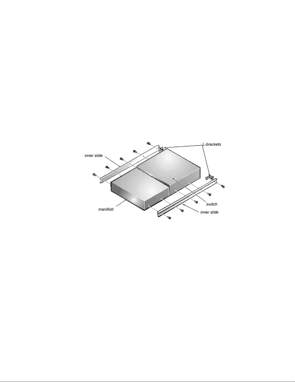
2. Align the holes of an inner bearing slide with the holes on the side of the manifold and the switch (see
Figure 1-2).
The end of the manifold that has the gasket should be toward the center of the inner bearing slide.
Make sure the rivets on the manifold a face up. The end of the inner bearing slide that has the two slots
should be at the end of the manifold without the gasket.
Align the switch to the inner bearing slide and orient the front of the switch (with the input/output ports)
toward the end of the bearing slide with the large hole. The back of the switch will compress the gasket
on the manifold.
Figure 1-2. Attaching the Inner Bearing Slides and L-Brackets
3. Use four 10-32 x 1/4-inch screws to mount the inner bearing slide to the switch and manifold.
4. Repeat steps 2 and 3 to mount the second inner bearing slide to the other side of the switch and
manifold.
5. Using 10-32 x 1/4-inch screws, mount an L bracket, with the captive thumb screws, to each inner slide,
as shown in Figure 1-2.
Installing the Outer Slides
To install the outer slide in the rack, perform the following steps:
1. Use a 10-32 x 1/2-inch screw to mount a stationary bracket to an outer slide, as shown in Figure 1-3.
Figure 1-3. Attaching Stationary and Adjustable Brackets to an Outer Slide
file:///C|/Users/sharon_anand/Desktop/PowerVault/50f_enit/INSTALL.HTM[3/15/2013 11:31:55 AM]
Page 9

Installing the PowerVault™ 50F Switch: Dell™ PowerVault™ 50F 8-Port Fibre Channel Switch Installation and Troubleshooting Guide
2. Use a 10-32 x 1/2 inch screw and a 10-32 nut with captive star washer to mount an adjustable bracket
to the other end of the outer slide, as shown in Figure 1-3. Do not completely tighten the screw.
3. Repeat steps 1 and 2 to mount the remaining stationary and adjustable brackets to the second outer
slide.
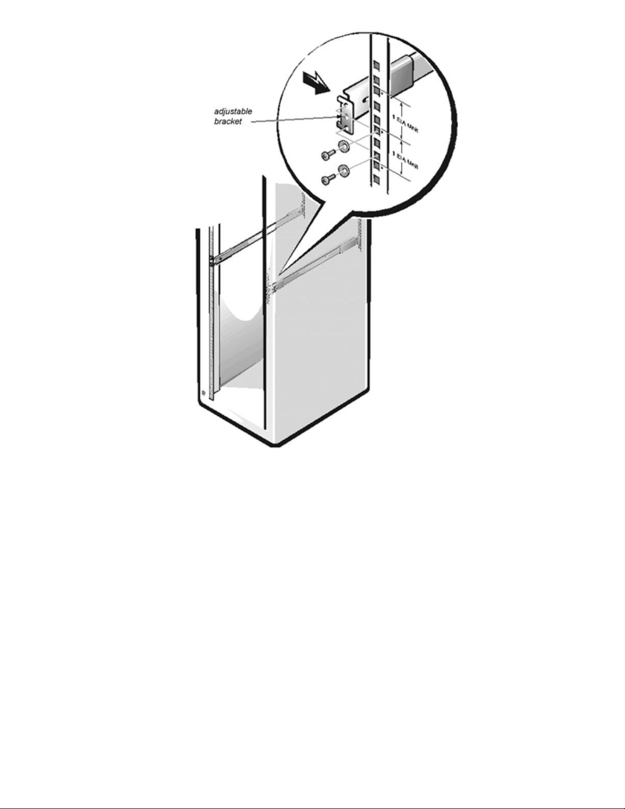
4. Use four 10-32 x 1/2-inch screws and four tapered washers to mount each outer slide in the rack, as
shown in Figure 1-4.
5. The stationary brackets attach to the rear of the rack. The adjustable brackets attach to the front. The
screws are threaded through the rack and into the top and bottom holes of the brackets, leaving the
middle bracket holes open.
NOTE: The slides must be mounted within 1 Electronic Industry Association (EIA) unit. The switch takes up 2 EIA
units with the outer bearing slides mounted in the lower of the 2 EIA units.
Figure 1-4. Mounting the Outer Slides and Bezel on the Rack
file:///C|/Users/sharon_anand/Desktop/PowerVault/50f_enit/INSTALL.HTM[3/15/2013 11:31:55 AM]
Page 10
Installing the PowerVault™ 50F Switch: Dell™ PowerVault™ 50F 8-Port Fibre Channel Switch Installation and Troubleshooting Guide
6. Tighten the screws holding the adjustable brackets to the outer slides.
Installing the Switch in the Rack
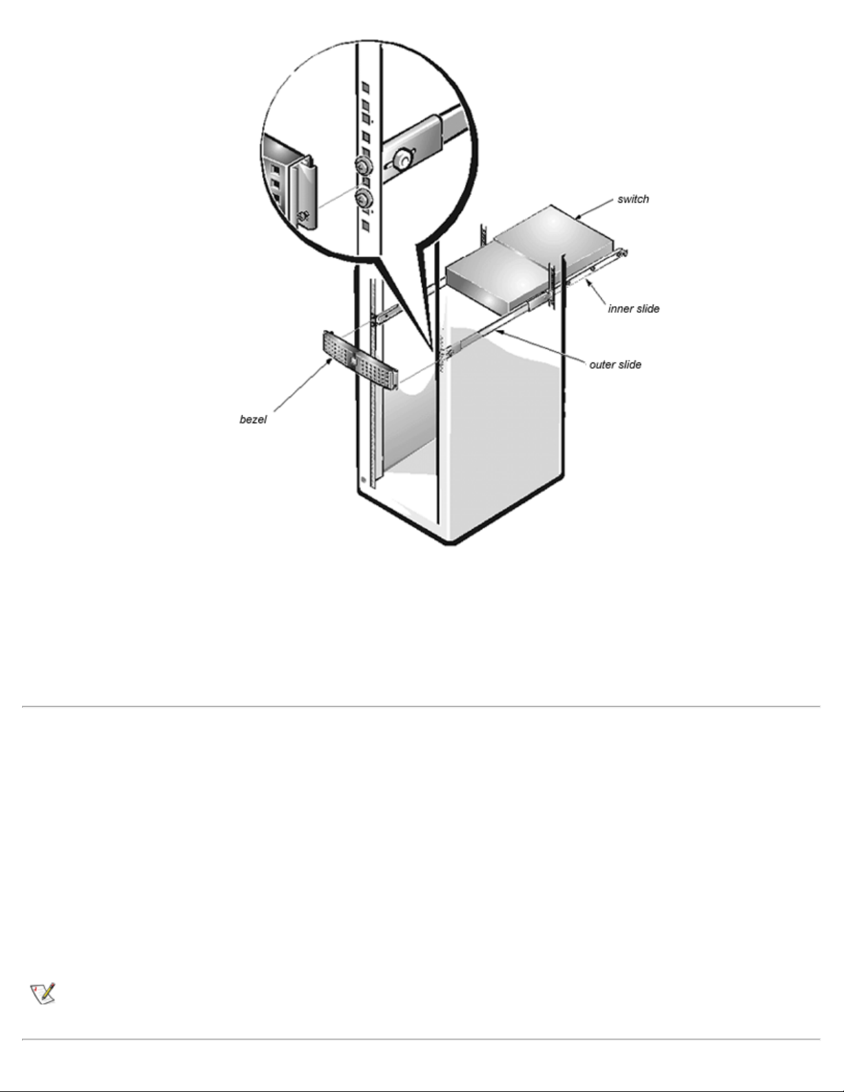
To install the switch in the rack, perform the following steps:
1. At the back of the rack, carefully align the switch's inner slides with the outer slides on the rack.
Slide the inner slides into the outer slides and push the switch all the way into the rack, as shown in
Figure 1-5. The two safety releases on the slides must be pressed for the switch to slide all the way in.
Figure 1-5. Installing the Switch in the Rack
file:///C|/Users/sharon_anand/Desktop/PowerVault/50f_enit/INSTALL.HTM[3/15/2013 11:31:55 AM]
Page 11
Installing the PowerVault™ 50F Switch: Dell™ PowerVault™ 50F 8-Port Fibre Channel Switch Installation and Troubleshooting Guide
2. Tighten the thumbscrews on the L-brackets to secure the switch to the rack.
3. Install the bezel onto the front of the rack, as shown in Figure 1-5.
The captive thumbscrews of the bezel pass through the rail holes and into the middle hole of the
adjustable brackets. Adjust the bezel so the manifold slides part way into it.
Stand-alone Mounting
The switch is shipped in its stand-alone configuration. Adhesive rubber feet are supplied if the switch is
surface-mounted. Installation of the rubber feet is optional, and is not required for proper or safe switch
operation.
To install the adhesive rubber feet, perform the following steps:
1. Use the alcohol wipes provided to clean the four depressions at each corner of the chassis bottom.
Allow the alcohol to dry.
2. Remove the rubber feet from the backing sheet and place one in each depression.
3. Firmly press the rubber feet in place.
NOTE: If rubber feet have been installed, they must be removed before the unit can be installed in a 19 -inch rack.
file:///C|/Users/sharon_anand/Desktop/PowerVault/50f_enit/INSTALL.HTM[3/15/2013 11:31:55 AM]
Page 12
Installing the PowerVault™ 50F Switch: Dell™ PowerVault™ 50F 8-Port Fibre Channel Switch Installation and Troubleshooting Guide
Fibre Channel Cable Connections
All network cable connections are on the switch's front panel. All recommended cabling supports the switch's
1-Gbps transfer rate, as shown in Table 1-1.
Table 1-1. Cabling Connections
Cable
type
Fiberoptic
Copper
Cable Specification Maximum Run
Length
Duplex SC plug
connectors
Multimode fiber
50 or 62.5 micrometers ( μm) core diameter
125 μm cladding diameter duplex cable
Impedance controlled for 150-ohm differential
systems
Low skew, shielded -quad, 150 - ohm cable
Polarized interface
HSSD receptacle
500 meters
(1641 feet)
12 meters (38 feet)
GBIC Module
770-850 μ
without open fiber
control (non- OFC)
SCA2 printed circuit board (PCB)
interface
HSSDC
input/output (I/O)
Various lengths of copper and optical cables are available from Dell. These cables have been designed and
approved by Dell. Dell recommends the use of these cables to ensure the proper operation of the
PowerVault™ 50F.
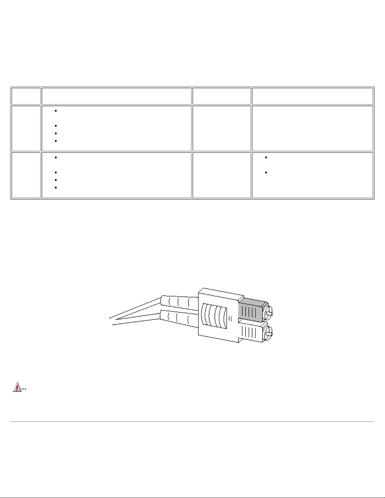
Fiber cable connections are made to the switch's front panel using standard dual SC plug connectors as
shown in Figure 1-6.
Figure 1-6. Dual SC Fiber-Optic Plug Connector
The connectors are indexed and must be inserted into the GBIC module's connector in proper alignment. In
most cases, one of the two connector plugs is a different color to aid in proper connector alignment.
CAUTION: Remove the protective plug from the GBIC module. Do not force the fiber- optic plug into the GBIC
module as you may damage the connector, the GBIC module, or both. Make certain the fiber surface is free of
dust or debris before inserting the connector into the GBIC module.
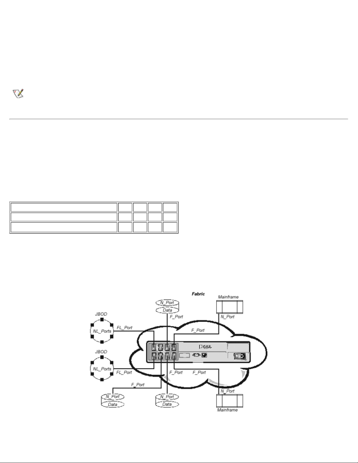
Fabric Connections (F_Port/FL_Port)
Fabric connections are determined by the number of connected devices, the required bandwidth, and circuit
redundancy required to service each connection to and within the Fabric. The F_Port is the Fabric access
file:///C|/Users/sharon_anand/Desktop/PowerVault/50f_enit/INSTALL.HTM[3/15/2013 11:31:55 AM]
Page 13

Installing the PowerVault™ 50F Switch: Dell™ PowerVault™ 50F 8-Port Fibre Channel Switch Installation and Troubleshooting Guide
port used to connect an N_Port (host connection). The FL_Port is the Fabric access port used to connect
NL_Ports to the switch in a loop configuration.
Refer to "Sample Fabric Topologies
" for some sample Fabric topologies.
Expansion Connections (E_Port)
Expansion (E_Port) connections are used to interconnect switches within a Fabric. Refer to "Sample Fabric
Topologies" for sample topologies using different E_Port connections to create different Fabric topologies.
Host and Target Connections (N_Port/NL_Port)
The connections to the Fabric are through Nx_Ports. Refer to "Sample Fabric Topologies" for examples of
various hosts and devices connected to Fabrics via their N_Port connections. The N_Port (host connection)
connects to the F_Port (Fabric connection). The NL_Port (arbitrated loop configuration) connects to the
FL_Port (Fabric connection).
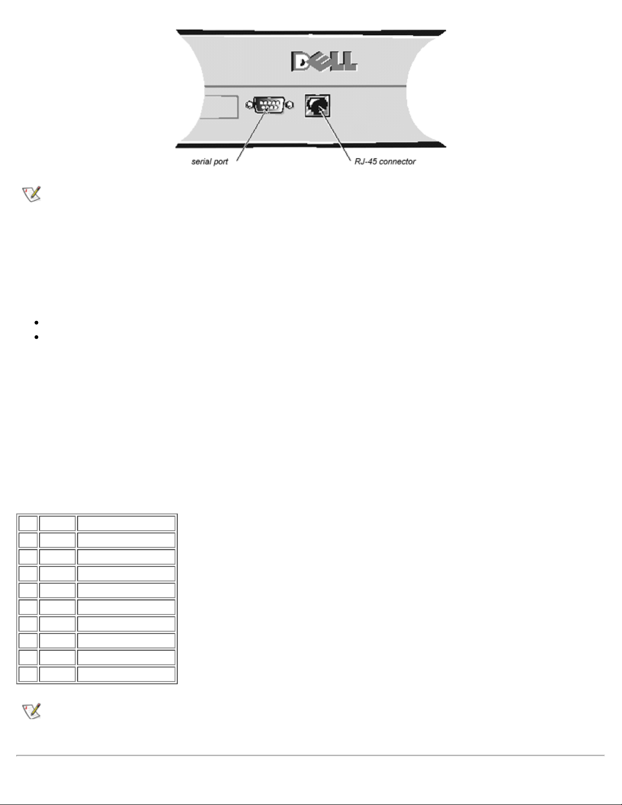
Ethernet Connection
Connecting an existing Ethernet 10BaseT local area network (LAN) to the switch via the front panel RJ-45
connector gives access to the switch's internal Simple Network Management Protocol (SNMP) agent,
allowing remote Telnet and Web access for remote monitoring and testing.
NOTE: The connection is only for Telnet, SNMP agent, and the Web-based server access. No Fabric connection is
available via this connection.
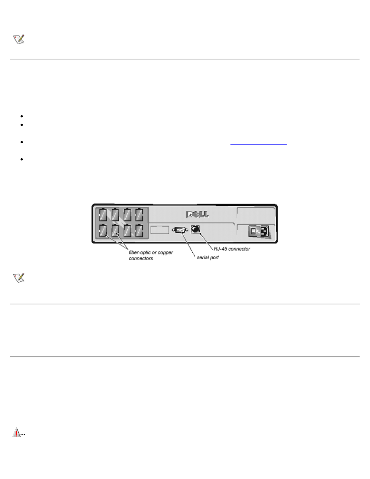
Serial Port Connection
The PowerVault™ 50F Switch includes a serial port (see Figure 1-7) used to set the Internet Protocol (IP)
address. The serial port is used to set the IP address when setting up or reinitializing a switch. The serial port
settings are as follows:
8 bit
No parity
One stop bit
9600 baud
Hyperterminal
VT100
Flow control = Xon/Xoff
Figure 1-7. Connections for PowerVault™ 50F Switch
file:///C|/Users/sharon_anand/Desktop/PowerVault/50f_enit/INSTALL.HTM[3/15/2013 11:31:55 AM]
Page 14
Installing the PowerVault™ 50F Switch: Dell™ PowerVault™ 50F 8-Port Fibre Channel Switch Installation and Troubleshooting Guide
NOTE: The serial port and Telnet connection are mutually exclusive and there can be only one serial port session active at
a time. Telnet takes priority, so the serial port is terminated when a Telnet connection is made. The serial connection is
restored after the Telnet session is completed, but you must log in again. A password is required to log in to the serial
port session. Password checking is skipped only at initial power on and remains off until log off is done.
System Configurations
In order to communicate with the RS-232 port, a computer system is required with the following:
Hyper terminal
An available COM port
Cables: A straight-through serial cable (DB9 female-to-female) connected between the DB9 serial
ports on the computer and switch. See Table 1-2 for pinout requirements. This cable is included in the
over-pack, shipped with your PowerVault™ 50F switch.
Serial Cabling and Emissions Requirements
The PowerVault™ 50F Switch uses a straight-through serial cable with a female 9-pin D-Subminiature
connector with the pinouts shown in Table 1-2. Only pins 2, 3, and 5 are required.
Table 1-2. Cabling Pinouts
Pin Signal Description
1 DCD Carrier Detect
2 TxData Transmit Data
3 RxData Receive Data
4 DTR Data Terminal Ready
5 GND Logic Ground
6 DSR Data Set Ready
7 RTS Request to Send
8 CTS Clear to Send
9 RI Ring Indicator
NOTE: For dust and electrostatic discharge (ESD) protection, the PowerVault™ 50F Switch includes a cover for the serial
port. When not in use, the serial port should be covered.
file:///C|/Users/sharon_anand/Desktop/PowerVault/50f_enit/INSTALL.HTM[3/15/2013 11:31:55 AM]
Page 15

Installing the PowerVault™ 50F Switch: Dell™ PowerVault™ 50F 8-Port Fibre Channel Switch Installation and Troubleshooting Guide
Verifying Power-On Self-Test (POST)
When powering on a switch, the switch conducts a series of diagnostic tests including:
Memory Test
Port Register Test
Central Memory Test
RDRAM Test
As the POST successfully performs each of the tests, the message Passed is displayed via the local RS232 serial port.
After the switch completes the POST, the GBIC module returns to a steady state from the flashing states
shown during the tests.
If an amber GBIC module light is displayed, there was a failure on that port during POST. See "Power-On
Diagnostics" for details.
If error conditions are encountered, they are displayed on the local RS-232 serial port after the switch
completes the POST. See "errShow" for details.
Setting IP Address Using the Serial Port
There is a label on the front panel of the PowerVault™ 50F Switch with IP address and space to include the
IP address when it is configured.
NOTE: This label facilitates identification of the physical switch in maintenance mode.
The serial port is initially logged on as Admin with no password required.
To set the IP address using the serial port, perform the following steps:
1. Connect the DB9 serial cable from the computer's COM port to the switch's
RS-232 port.
2. Start the Hyper Terminal by selecting Programs—> Accessories—> Hyper Terminal and then
hyperterm.exe
Supply a name in the Connection Description dialog box.
Enter Direct to Com <port#> in the Connect Using dialog box.
The COM <port#> Properties dialog box is displayed with the following settings:
8-bit
No parity
One stop bit
9600 baud
Hyperterminal
VT100
Flow control = Xon/Xoff
3. Turn on the switch and read the messages on the screen.
4. Run the ipAddrSet command.
file:///C|/Users/sharon_anand/Desktop/PowerVault/50f_enit/INSTALL.HTM[3/15/2013 11:31:55 AM]
Page 16

Installing the PowerVault™ 50F Switch: Dell™ PowerVault™ 50F 8-Port Fibre Channel Switch Installation and Troubleshooting Guide
Resetting Factory Defaults
In the event that a user changes a password or IP address, or forgets it, or sets an invalid IP address, the IP
address can be reinitialized.
To reset factory defaults, perform the following steps:
1. Connect the DB9 serial cable from the computer's COM port to the switch's
RS-232 port.
2. Start the Hyper Terminal by selecting Programs—> Accessories—> Hyper Terminal, and then
hyperterm.exe.
Supply a name in the Connection Description dialog box.
Enter Direct to Com <port#> in the Connect Using dialog box.
The COM <port#> Properties dialog box is displayed with the following settings:
8-bit
No parity
One stop bit
9600 baud
Hyperterminal
VT100
Flow control = Xon/Xoff
3. Turn on the switch and read the messages on the screen.
4. Run the flashDefault command.
Back to Contents Page
file:///C|/Users/sharon_anand/Desktop/PowerVault/50f_enit/INSTALL.HTM[3/15/2013 11:31:55 AM]
Page 17
PowerVault™ 50F Topologies: Dell™ PowerVault™ 50F 8-Port Fibre Channel Switch Installation and Troubleshooting Guide
Back to Contents Page
PowerVault™ 50F Topologies: Dell™ PowerVault™ 50F 8-Port
Fibre Channel Switch Installation and Troubleshooting Guide
Overview • Fabric Elements • Sample Fabric Topologies
Overview
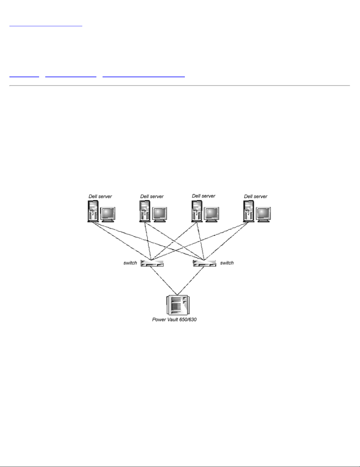
Figures 2-1, 2-2, and 2-3 show the topologies supported by Dell. The PowerVault™ 50F Switch has the
capability of supporting other topologies, but they have not been validated and are currently not supported by
Dell.
These configurations require the use of Dell OpenManage™ Storage Consolidation software. See the
documentation that came with the Dell OpenManage™ Storage Consolidation software for installation and
operating instructions.
Figure 2-1. Topology Example 1
Figure 2-2. Topology Example 2
file:///C|/Users/sharon_anand/Desktop/PowerVault/50f_enit/POWER.HTM[3/15/2013 11:31:57 AM]
Page 18
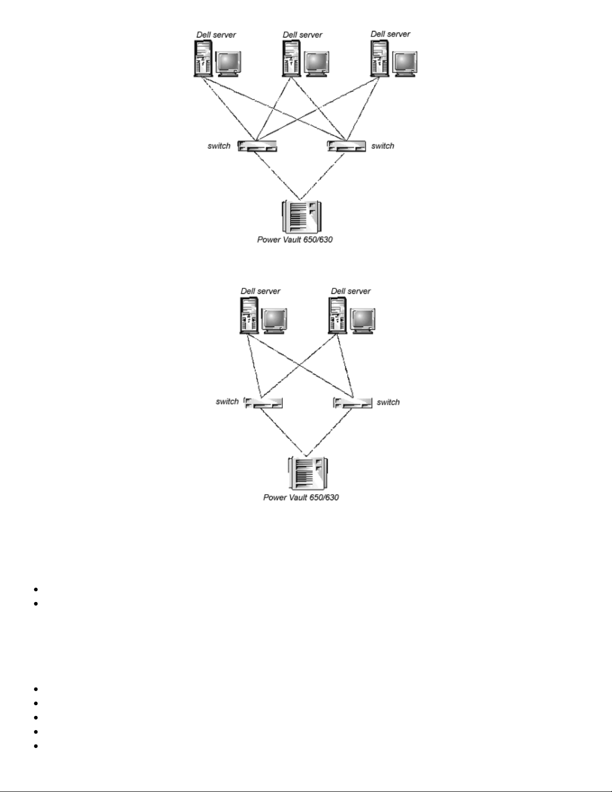
PowerVault™ 50F Topologies: Dell™ PowerVault™ 50F 8-Port Fibre Channel Switch Installation and Troubleshooting Guide
Figure 2-3. Topology Example 3
Fabric performance depends on numerous factors. This chapter discusses some key factors, but is not a
complete catalogue of variables to consider when structuring a Fabric.
This chapter includes:
Fabric elements
Sample Fabric topologies
Fabric Elements
Each Fabric is unique, and the elements that determine the Fabric's structure include:
Class of frames in the Fabric
Type of host adapters connected to the Fabric
Bandwidth requirements supported by the Fabric
Topology of the switches in the Fabric
Requirements for redundancy and fault tolerance
file:///C|/Users/sharon_anand/Desktop/PowerVault/50f_enit/POWER.HTM[3/15/2013 11:31:57 AM]
Page 19

PowerVault™ 50F Topologies: Dell™ PowerVault™ 50F 8-Port Fibre Channel Switch Installation and Troubleshooting Guide
Regardless of the topology used, the switch's extremely low message latency minimizes Fabric message
handling time that results in a high-performance Fabric.
Routing Cost
All Inter Switch Links (ISLs) have a default cost of 1000. The cost of a path between any two switches in the
Fabric is the sum of the costs of all ISLs. The switches that comprise the Fabric always choose the lowest
cost path through the Fabric to forward frames from the source switch to the destination switch.
When constructing a multiswitch configuration, called a cascaded Fabric, a frame entering the Fabric may
pass through eight switches before exiting the Fabric. The switch does not enforce the eight-switch limit. It is
your responsibility to ensure that the seven-hop limit is not exceeded. The command uRouteShow provides
information regarding the cost of the shortest path to another switch from which you can derive the number
of hops. The cost should not exceed 7000 (7 x 1000).
A Fabric using Dell switches in cascaded topologies should be configured to deliver the required bandwidth
and fault tolerance with all connections made within the seven-hop maximum limit.
Configuring Switches
When configuring switches in a Fabric, optimize the Fabric performance based on the most significant
expected use.
NOTE: Except for unique identifiers such as the switch name, domain name, and IP address, all switches in a Fabric must
have the same firmware configuration. Switches that are configured differently are isolated from the Fabric.
Cascaded topologies using multiple switches give switching system designers a powerful, flexible set of
resources to create high-performance, robust storage area networks (SAN), or data center backbone.
Loop Support
The FL_Port interface card enables any Fabric-connected device to communicate with public or private fibre
channel disks or other device types.
NOTE: Loops may contain any combination of public or private loop devices.
Public Operation
In public operation, all loop devices are accessible to all other Fabric-connected devices and loop devices
within the Fabric. The loop devices behave the same as devices attached directly to the Fabric.
Private Operation
Dell's FL_Port translative mode allows private devices on a local loop to communicate with Fabric-attached
devices and vice versa. Fabric-attached devices can be either N_Ports attached to G_Ports or public
NL_Ports attached to other FL_Ports.
Logically, private and Fabric-attached devices that communicate to a loop appear to be devices on the same
loop as the private devices. Each Fabric-attached device uses an unassigned AL_PA from the local loop.
When private devices on a local loop and Fabric-attached devices communicate, the FL_Port automatically
file:///C|/Users/sharon_anand/Desktop/PowerVault/50f_enit/POWER.HTM[3/15/2013 11:31:57 AM]
Page 20
PowerVault™ 50F Topologies: Dell™ PowerVault™ 50F 8-Port Fibre Channel Switch Installation and Troubleshooting Guide
translates between private and public addresses.
The FL_Port translative mode supports up to 32 Fabric-attached devices (one is reserved for the Fabric)
appearing on each local loop of private devices, subject to the limit of 126 devices on a loop (the total of
private and Fabric-attached devices).
Private devices are registered to the Simple Name Server (SNS), so the Fabric-attached devices can query
SNS for their addresses and initiate communication.
NOTE: The translative mode is automatically enabled with the FL_Port card and no user intervention is necessary to
configure the translative mode.
Sample Fabric Topologies
The following Fabric topology samples show several different conceptual topology models. Each installation
has a unique topology that is determined by the characteristics of the connected devices and your
performance objectives.
In the following samples, only the single switch Fabric solution shows connections to the Fabric. The switch
numbering scheme is:
Interface cards 1 2 3 4
Ports 0 2 4 6
1 3 5 7
Single-Switch Fabric
The simplest Fabric consists of a single-switch topology as shown in Figure 2-4.
Figure 2-4. Single-Switch Topology Sample
Figure 2-4 shows the switch's F_Ports and FL_Ports and the corresponding N_Port and NL_Port
connections on the device side. The switch connections are shown as they would be in a physical
file:///C|/Users/sharon_anand/Desktop/PowerVault/50f_enit/POWER.HTM[3/15/2013 11:31:57 AM]
Page 21
PowerVault™ 50F Topologies: Dell™ PowerVault™ 50F 8-Port Fibre Channel Switch Installation and Troubleshooting Guide
installation. Functionally, the switch becomes a Fabric with every device connected to every other device by
the Fabric.
Each connection is full duplex with transmissions up to 1 Gbps bandwidth simultaneously, in both directions,
between the Fabric and Fabric-connected devices.
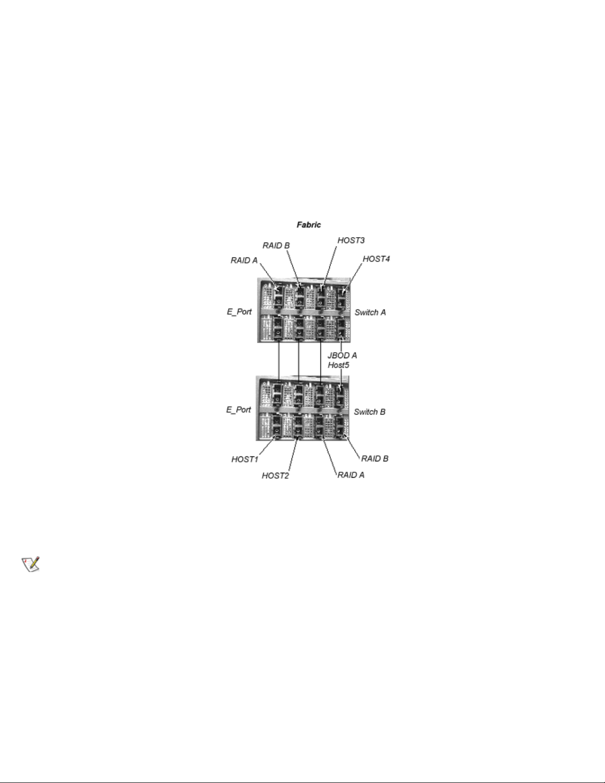
Two-Switch Sample Topology
The two-switch topology increases the number of connectivities and aggregate Fabric bandwidth, as shown
schematically in Figure 2-5. The switches are shown physically connected although the connections are
transparent in the Fabric. Functionally, the devices appear to be connected together directly.
Figure 2-5. Fabric Topology Sample With Three Connections Between Two Switches
When a Fabric is initiated, or when a new switch is added to the Fabric, the switches determine a least-cost
path for each destination switch. This is done dynamically each time the Fabric configuration changes and
the results are stored in the switch's internal routing tables.
NOTE: After a path has been determined, it is not rerouted, even though traffic volume may change over time, for each
path to maintain in-order delivery. If the link fails, the path is rerouted.
Increasing Local Bandwidth within the Fabric
In Figure 2-5, three connections are shown between Switch A and Switch B. This gives an aggregate
bandwidth of six Gbps - three 1-Gbps, full-duplex connections. Increasing bandwidth between switches is
done by adding additional connections between the switches.
In addition to the bandwidth, redundant connections between the switches in Figure 2-5 provide a highbandwidth, fault-tolerant Fabric.
Four-Switch Sample Topology
file:///C|/Users/sharon_anand/Desktop/PowerVault/50f_enit/POWER.HTM[3/15/2013 11:31:57 AM]
Page 22
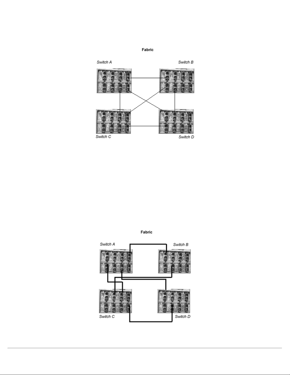
PowerVault™ 50F Topologies: Dell™ PowerVault™ 50F 8-Port Fibre Channel Switch Installation and Troubleshooting Guide
Figure 2-6 shows a four-switch topology that adds additional paths to the Fabric topology, increasing the
Fabric's reliability, bandwidth, fault tolerance, and connections.
Figure 2-6. Four-Switch Fabric Topology Sample
For example, the shortest path between switch A and switch D would be the direct path AD. If this path were
to fail, the connection would then be automatically routed through either switch B or C with a path of ABD or
ACD.
In Figure 2-6, ports 6 and 7 on the interface module in position 4 of switch A are used for connection to
switch B and switch D. If the interface module failed, traffic to switch B, C, and D would all have to be
rerouted between the interface modules in the third position on switches A and C.
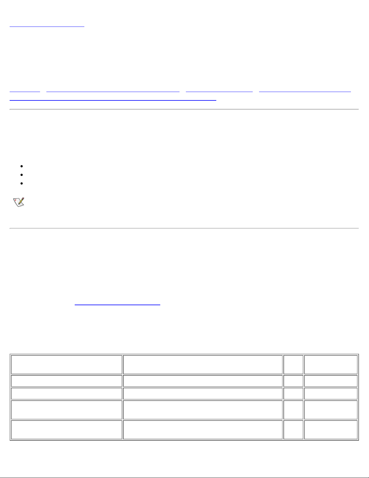
A more robust solution is to have all connections distributed across available interface cards in each switch,
giving an alternate configuration as shown in Figure 2-7.
Figure 2-7. Four-Switch Fabric Topology Sample
If bandwidth or fault tolerance is a concern, each of the paths shown in Figure 2-7 could have a parallel
connection.
file:///C|/Users/sharon_anand/Desktop/PowerVault/50f_enit/POWER.HTM[3/15/2013 11:31:57 AM]
Page 23

PowerVault™ 50F Topologies: Dell™ PowerVault™ 50F 8-Port Fibre Channel Switch Installation and Troubleshooting Guide
Back to Contents Page
file:///C|/Users/sharon_anand/Desktop/PowerVault/50f_enit/POWER.HTM[3/15/2013 11:31:57 AM]
Page 24
Managing the PowerVault™ 50F Switch: Dell™ PowerVault™ 50F 8-Port Fibre Channel Switch Installation and Troubleshooting Guide
Figure 3-1 shows the various methods and communication paths for accessing switch management
Back to Contents Page
Managing the PowerVault™ 50F Switch: Dell™ PowerVault™ 50F
8-Port Fibre Channel Switch Installation and Troubleshooting
Guide
Overview • Comparing Switch Management Methods • Managing Via Telnet • Managing with SNMP Under
Dell OpenManage™ and the PowerVault™ 50F Switch Manager
Overview
This chapter contains general information and examples on managing and monitoring the switch. The
following are discussed:
Switch management methods
Managing via Telnet
Managing with SNMP under Dell OpenManage™ and the PowerVault™ 50F Switch Manager
NOTE: You must assign an Internet Protocol (IP) address to the switch via the local RS- 232 serial port before you can
access some of the management methods described.
Comparing Switch Management Methods
The switch is managed locally via a computer running a terminal program attached to the RS-232 serial port
and remotely via Telnet or Web management (PowerVault™ 50F Switch Manager).
Before changing any of the factory default settings, become familiar with the operations described in this
chapter including both the switch's functions and interactive characteristics. To reset a switch to factory
default values, see "Resetting Factory Defaults
There are several access methods for managing a switch. Table 3-1 summarizes the different management
methods.
Table 3-1. Comparison of PowerVault™ 50F Switch Management Methods
Method Description Local
".
Out-of-band
(Ethernet)
Serial port Managed via RS- 232 serial port located on the switch Yes No
Telnet commands Managed remotely using Telnet commands No Yes
Managing with SNMP Managed remotely using Simple Network Management
Protocol (SNMP)
PowerVault™ 50F Fibre Channel
Switch Manager
file:///C|/Users/sharon_anand/Desktop/PowerVault/50f_enit/MANAGE.HTM[3/15/2013 11:31:58 AM]
Managed remotely though web No Yes
No Yes
Page 25
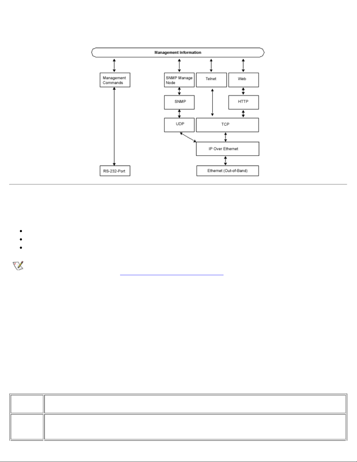
Managing the PowerVault™ 50F Switch: Dell™ PowerVault™ 50F 8-Port Fibre Channel Switch Installation and Troubleshooting Guide
information.
Figure 3-1.Methods for Managing PowerVault™ 50F Switch Information
Managing Via Telnet
To make a successful Telnet connection to a switch, the following is required:
Switch name or IP address
Username
Password
NOTE: The IP address must be set using the ipAddrSet command, which can be issued by connecting to the RS -232
serial port on the front panel. See "Setting IP Address Using the Serial Port
Consult with the local network system administrator for the IP address that is assigned to the switch.
The serial port and Telnet connection are mutually exclusive and there can be only one serial port session active at a time.
Telnet takes priority, so the serial port is terminated when a Telnet connection is made. The serial connection is restored
after the Telnet session is completed but re-logging in is required. A password is required to login to the serial port
session. Password checking is skipped only at initial power on and remains off until log off is done.
Default Username
Each Username has a security level associated with it. Username 3 is the least privileged and the security
level goes up to Username 0, which is the most privileged.
" for more information.
Table 3-2. Default Username
Default
Username Description
other
(Username
3)
file:///C|/Users/sharon_anand/Desktop/PowerVault/50f_enit/MANAGE.HTM[3/15/2013 11:31:58 AM]
Gives users access to execute commands ending in Show, such as dateShow.
Page 26

Managing the PowerVault™ 50F Switch: Dell™ PowerVault™ 50F 8-Port Fibre Channel Switch Installation and Troubleshooting Guide
user
(Username
2)
admin
(Username
1)
Gives users access to all Show commands plus any commands in the help menu that do not change a switch
state, such as version. This level is the recommended level for monitoring switch activity.
Gives users access to all Show commands, plus any commands in the help menu. Most switch administration is
performed at this level.
The system administrator may assign different usernames than those listed, if desired. The user at a
particular security level, however, has the same privileges regardless of the name assigned.
Changing Passwords
The initial default password for all usernames is password. Change the default passwords during
installation to meet the Fabric's security requirements.
To change user passwords, perform the following steps:
1. Log in as admin.
2. Issue the command passwd.
3. Each username (admin, user, other) is displayed in sequence, allowing the admininstrator to modify
each password and name.
4. Enter a password or name while a username is displayed to replace the existing password or name.
NOTE: If you lose the password, contact Dell Technical Support.
Managing with SNMP Under Dell OpenManage™ and the PowerVault™ 50F Switch
Manager
The resident SNMP manage node allows remote switch management via IP over Ethernet and Fibre
Channel interfaces.
Dell Openmanage integrates the PowerVault™ 50F Switch through HP OpenView Network Node Manager
Special Edition (NNM SE) in a Windows NT environment. You can use Dell OpenManage™ to manage this
device. If you have a PowerVault™ 50F Switch connected in your network, it will be automatically discovered
as a node in the node submap of HP OpenView NNM SE. In order to launch the PowerVault™ 50F Switch
Management Application, double-click on the discovered FC-Switch node to access the expanded node
submap, and then double click on the Switch Management Application icon.
Refer to your HP OpenView Network Node Manager Special Edition 1.4 with Dell OpenManage™ HIP 3.4
User's Guide for more information on Dell OpenManage.
The switch's manage node supports the following:
SNMPv1 manager
Command line utilities to provide access to and command the manage node
MIB-II system group, interface group, and SNMP group
Fabric Element MIB
Vendor-Specific MIBs
Standard Generic traps
file:///C|/Users/sharon_anand/Desktop/PowerVault/50f_enit/MANAGE.HTM[3/15/2013 11:31:58 AM]
Page 27

Managing the PowerVault™ 50F Switch: Dell™ PowerVault™ 50F 8-Port Fibre Channel Switch Installation and Troubleshooting Guide
SNMP Transports
The SNMP manage node residing on the embedded processor supports UDP/IP over the Ethernet interface
or any FC-IP interface (see Figure 3-1
). This transport provides an immediate Plug and Play support for the
switch once the IP address has been assigned.
MIB-II Support
There are eleven groups of objects specified in MIB-II. The switch's SNMP manage node supports three of
these groups. The eight additional groups do not apply.
The three groups supported include the following:
System group (object ID is {iso, org, dod, internet, mgmt, mib-2, 1})
Interfaces group (object ID is {iso, org, dod, internet, mgmt, mib-2, 2})
SNMP group (object ID is {iso, org, dod, internet, mgmt, mib-2, 11})
The following variables are modifiable via the SNMP set command, given an appropriate community with
read-write access.
sysDescr System description: the default value is set as Fibre Channel Switch
sysObjectID System object identifier vendor's authoritative identification (1.3.6.1.4.1.1588.2.1.1.1)
sysUpTime The time since the manage node was last initialized
sysContact The identification and contact information for this system. By default, this is set as Field Support.
sysLocation The node's physical location. The default setting is End User Premise .
The interface group supports three interface drivers: software loopback, Ethernet, and Fibre Channel IP. Dell
is not currently supporting Fibre Channel IP.
Fabric Element MIB Support
The following five object groups are defined:
Configuration group
Operation group
Error group
Accounting group
Capability group
The manage node supports all groups.
PowerVault™ 50F Switch Vendor Unique MIB
The following five object groups are defined:
PowerVault™ 50F System Group
Fabric Group
SNMP manage node Configuration Group
Fibre Channel Port Group
file:///C|/Users/sharon_anand/Desktop/PowerVault/50f_enit/MANAGE.HTM[3/15/2013 11:31:58 AM]
Page 28

Managing the PowerVault™ 50F Switch: Dell™ PowerVault™ 50F 8-Port Fibre Channel Switch Installation and Troubleshooting Guide
Name Server Group
Generic Traps
Setting up the switch's SNMP connection to an existing managed network allows the network system
administrator to receive the following generic traps:
coldStart — indicates the manage node has reinitialized itself such that the manage node's
configuration can be altered.
warmStart — indicates the manage node has reinitialized itself, but no configuration has changed.
linkDown — indicates an IP interface (Ethernet, loop back, or embedded N_Port) has gone down and is
not available.
linkUp — indicates an IP interface (Ethernet, loop back, or embedded N_Port) has become available.
authenticationFailure — indicates the manage node has received a protocol message that is not
properly authenticated. This trap, by default, is disabled but can be enabled via the command
agtcfgSet
Enterprise Specific Traps
Three Enterprise Specific Traps are supported:
swFault — indicates that the diagnostics detect a fault with the switch.
swSensorScn — indicates that an environment sensor changes its operational state (for example, a fan
stops working). The VarBind in the Trap Data Unit contains the corresponding instance of the sensor
status.
swFCPortScn — a notification that a Fibre Channel Port changes its operational state (for instance, the
Fibre Channel Port goes from online to offline). The VarBind in the Trap Data Unit contains the
corresponding instance of the port's operational status.
NOTE: SNMP swFCPortScn traps are generated on GBIC insertion and removal even though the state remains offline.
Manage Node Configuration
Changes to SNMP from either Telnet or SNMP are not displayed in SNMP until the switch is rebooted
running. This is due to SNMP running from cache while the active settings are running from the flash PROM.
The configurable parameters include the following:
SNMPv1 communities (up to 6)
Trap recipients (1 per community)
sysName
sysLocation
authenticationFailure — indicates the manage node has received a protocol message that is not
properly authenticated. This trap, by default, is disabled but can be enabled via the command
agtcfgSet.
The sysX parameters can be configured via the SNMPv1 SET command with an appropriate community.
These parameters can be configured via a Telnet connection, using the command agtcfgSet.
NOTE: A change in the first two configuration parameters takes effect only after rebooting the switch.
file:///C|/Users/sharon_anand/Desktop/PowerVault/50f_enit/MANAGE.HTM[3/15/2013 11:31:58 AM]
Page 29

Managing the PowerVault™ 50F Switch: Dell™ PowerVault™ 50F 8-Port Fibre Channel Switch Installation and Troubleshooting Guide
Name Server
The fibre channel protocol (FCP) inquiry data obtained by device probing may now be obtained from the
Name Server by retrieving the port symbolic name.
Common Transport (CT) requests and responses including Name Server are recorded in the portLog. A
typical trace is shown as follows, where port 4 logs in to the Name Server and issues command 217. It
receives an Accept (8002).
Jun 15 16:00:21.899 tReceive Rx3 4 116
22fffffc,00210413,03000000
Jun 15 16:00:21.899 tSwitch Tx3 4 116
23210413,00fffffc,02000000
Jun 15 16:00:21.933 tNSd ctin 4 fc
00030217,00210413,00000100
Jun 15 16:00:21.933 tNSd ctout 4 fc 00008002
Jun 15 16:00:21.933 tNSd Tx3 4 0
03210413,00fffffc
Back to Contents Page
file:///C|/Users/sharon_anand/Desktop/PowerVault/50f_enit/MANAGE.HTM[3/15/2013 11:31:58 AM]
Page 30

Introducing PowerVault™ 50F Fibre Channel Switch Manager: Dell™ PowerVault™ 50F 8-Port Fibre Channel Switch Installation and Troubleshooting Guide
Back to Contents Page
Introducing PowerVault™ 50F Fibre Channel Switch Manager:
Dell™ PowerVault™ 50F 8-Port Fibre Channel Switch Installation
and Troubleshooting Guide
Overview • Everyday Management • Managing Switch(es) Remotely • Switch Management Tools •
Administrative Functions
Overview
Use the PowerVault™ 50F Fibre Channel Switch Manager (Web interface) to log onto a switch from a host
with a Java-enabled Web browser via the Internet or Intranet to remotely manage a Server-Storage Area
Network (SAN) composed of switches and other SAN devices. PowerVault™ 50F Fibre Channel Switch
Manager allows you to dynamically interact with any switch in the SAN to monitor status and performance.
You use the available information to make overall topology decisions (for example, increasing a path's
bandwidth due to data saturation). Additionally, you can change a switch's configuration or download
firmware. The Administrative Interface and Telnet provide the means to make administrative changes, and
security is enforced by username and encrypted password.
This chapter discusses the following information about managing and monitoring a switch using
PowerVault™ 50F Fibre Channel Switch Manager:
Everyday management
Managing switch(es) remotely
Switch management tools (five screens)
Administrative functions (two screens)
Everyday Management
Everyday management includes the following range of tasks:
Monitoring port and switch operations
Evaluating port, switch, and network performance
Gathering statistics
Troubleshooting problems
Configuring the switch and the network topology
Managing Switch(es) Remotely
Using the PowerVault™ 50F Fibre Channel Switch Manager and a familiar Web browser, you can manage a
complex SAN, comprising multiple switches, as follows:
Switch identification in network
Fabric topology/routing information
Switches/ports general configuration
file:///C|/Users/sharon_anand/Desktop/PowerVault/50f_enit/CHANNEL.HTM[3/15/2013 11:31:59 AM]
Page 31

Introducing PowerVault™ 50F Fibre Channel Switch Manager: Dell™ PowerVault™ 50F 8-Port Fibre Channel Switch Installation and Troubleshooting Guide
Real-time graphical switch/port status and statistics report
— Port performance shown graphically (polled up to 2.5 seconds depending on operating system and
browser used)
— Four minutes of aggregate bandwidth throughput (polled up to 2.5 seconds depending on operating
system and browser used) shown graphically, scaled dynamically, based on activity
— Management with security protection via:
- Graphical User Interface (GUI)
- Management by Telnet commands (Telnet session)
Screen views
— Five for monitoring and gathering information
— Two for administrative interfaces
Help functions
— Pop-up help for error conditions
— Glossary help
— Online help HTML pages
Interface
— Out-of-band via a 10BaseT Ethernet connection
Switch Management Tools
The management tools provide five screens, as described in the following subsections.
Fabric View Page
The Fabric View Page shows the number of network switches and confirms worldwide names, domain IDs,
and switch names, if applicable.
Fabric Topology View Page
The Fabric Topology View Page shows the physical configuration including active domains, paths and
routing information. For example, the hop count which is the number of switches that handle a data frame
from origination through to the destination.
General Switch View Page
The General Switch View Page displays switch enclosure information, confirms general switch information,
and includes GUI buttons for quick access to the Administrative Interface, Telnet, and the Performance View.
The front panel identifies the type of interface module installed in each switch slot, the industry media (GBIC,
or Gigabit Interface Converter) used by the ports, and each port's light-emitting diode (LED) status. From this
view, more information is available about the switch by moving to either the Performance View or the Port
Detail View.
file:///C|/Users/sharon_anand/Desktop/PowerVault/50f_enit/CHANNEL.HTM[3/15/2013 11:31:59 AM]
Page 32

Introducing PowerVault™ 50F Fibre Channel Switch Manager: Dell™ PowerVault™ 50F 8-Port Fibre Channel Switch Installation and Troubleshooting Guide
Performance View Page
The Performance View Page graphically shows real-time data throughput for each port and switch bandwidth
utilization.
The two types of performance data shown are the throughput of each port and total switch throughput.
Bandwidth utilization is critical information needed to make decisions about optimizing performance, for
instance, if one port begins to handle a disproportionate amount of traffic.
Port Detail View Page
The Port Detail View Page shows statistics and general information for all ports, including LED status.
The Port Detail View appears for whatever port you select in the General Switch View. Once in this view,
every port for that switch may be viewed sequentially, by selecting its file folder. Each folder's tab replicates
the port's LED status which allows you to monitor all port status at the same time. Port details include
statistics about frames, interrupts, and errors that are helpful when troubleshooting.
Administrative Functions
The administrative functions provide two screens for secured interfaces, as described in the following
subsections:
Administrative Interface Page
The Administrative Interface Page is used to perform routine functions, such as upgrading firmware versions,
changing passwords, or switch reconfigurations.
Telnet Interface Page
The Telnet Interface Page uses Dell's superset of Telnet commands (configuration, diagnostics, displaying,
and routing) for switch diagnostics, troubleshooting, and management.
Back to Contents Page
file:///C|/Users/sharon_anand/Desktop/PowerVault/50f_enit/CHANNEL.HTM[3/15/2013 11:31:59 AM]
Page 33

PowerVault™ 50F Fibre Channel Switch Manager Operational Concepts: Dell™ PowerVault™ 50F 8-Port Fibre Channel Switch Installation and Troubleshooting ...
Back to Contents Page
PowerVault™ 50F Fibre Channel Switch Manager Operational Concepts: Dell™ PowerVault™ 50F 8-Port Fibre Channel Switch Installation and Troubleshooting Guide
Overview • Using the Web Interface • Fabric View Page • Fabric Topology View Page • General Switch View
Page • Port Detail View Page • Performance View Page • Administrative Interface Page • Telnet Interface
Page
Overview
This chapter discusses the PowerVault™ 50F Fibre Channel Switch Manager operational concepts. When
using the PowerVault 50F Fibre Channel Switch Manager, note the following:
Clickable areas are highlighted with a hint displayed in the left-side bottom bar of your browser when
the mouse is positioned over them.
When making changes in the admin page, the Response Page shows whether each individual
configuration change was committed or rejected.
Java is disabled in some versions of Netscape and must be enabled by checking both Enable Java
and Enable Java Script buttons in the Preferences/Advanced menu.
Netscape or Internet Explorer may hang with Java applications on Microsoft™ Windows NT™ after
SP3 due to True Color. To resolve this problem, either change the NT display settings to other than
True Color, or download the hotfix to modify win32k.sys. The hotfix is available from Microsoft
Technical Support.
When a Fabric Topology View Page is already open, clicking the Fabric Topology button from the
Fabric View Page will not cause the Fabric Topology View Page to rise to the top as the active
window. In this situation, use the taskbar to reactivate the Fabric Topology View Page.
When a Port Detail View Page is already open, clicking a port button from the General Switch View
Page will not cause the Port Detail View Page to rise to the top as the active window. In this situation,
use the taskbar to reactivate the Port Detail View Page.
When a Performance View Page is already open, clicking the Perform button from the General
Switch View Page will not cause the Performance View Page to rise to the top as the active window.
In this situation, use the taskbar to reactivate the Performance View Page.
Using the Web Interface
The Web interface switch management system provides a Graphical User Interface (GUI) for users to display
Fabric topology, general switch information, port traffic statistics and throughput performance. The GUI
enables switch administrators to configure the switch and its ports.
Controlling the Web Interface
When you position the cursor over an object (such as a port or the thermometer) and click, an informational
screen is displayed. In some instances, you can change the definitions by completing text fields (see
"Administrative Interface Page
file:///C|/Users/sharon_anand/Desktop/PowerVault/50f_enit/CONCEPT.HTM[3/15/2013 11:32:00 AM]
" for more information).
Page 34

PowerVault™ 50F Fibre Channel Switch Manager Operational Concepts: Dell™ PowerVault™ 50F 8-Port Fibre Channel Switch Installation and Troubleshooting ...
Fabric View Page
The Fabric View Page is the first Web page displayed (see "Fabric View Page" for details). This is a global
page and shows all switches present that comprise the Fabric. Note that switch in the Fabric can show the
overall Fabric view; therefore, it is not critical which switch is accessed initially.
The Fabric View Page uses switch names to connect to individual switches. This means you give each
switch a unique name (see Table 6-5 for information on how to use the switchName command), and this
name should match the correct Internet Protocol (IP) address by the name resolution protocol in use by the
Web client (NIS, DNS, etc.).
If a switch name is not recognized by the name resolution protocol, it may be accessed by typing in its IP
address from the Fabric View Page (double-click on the switch image while pressing down the <Shift> key
to open a dialog box and enter the IP address or host name).
Fabric Topology View Page
The Fabric Topology View Page shows the physical configuration, including active domains and paths, and
routing information (see "Fabric Topology View Page
").
General Switch View Page
The General Switch View Page shows a graphic representation of the switch's front panel (see "General
Switch View Page" for details). Normal long-term monitoring is conducted from this page, which provides a
real-time view of each switch's overall health and status in the Fabric. Note that if a switch has a problem, a
pop-up message is displayed explaining what problem has been detected.
Port Detail View Page
The Port Detail View Page provides statistics for each port (see "Port Detail View Page " for details). The
page features cascaded folders, one for each port. Each folder has a tab on the top to show the port number
and a status light to tell the port state.
Performance View Page
The Performance View Page displays port and switch throughput in bytes per second (see "Performance
View Page" for details). Each port is numbered and throughput for the entire switch is displayed under the
individual port readings.
Administrative Interface Page
The Administrative Interface Page is used to enable (or disable) the switch or ports (see "Administrative
Interface Page" for details). Change switch name, date/time, IP addresses, user name, passwords,
download flash, and reboot switch via this page. Only users with admin privilege can access this page. Any
changes made through this page may fundamentally change the switch/port status and its role in the fabric.
Telnet Interface Page
The Telnet Interface Page allows you to launch a Telnet session directly from your Web browser. Only
file:///C|/Users/sharon_anand/Desktop/PowerVault/50f_enit/CONCEPT.HTM[3/15/2013 11:32:00 AM]
Page 35

PowerVault™ 50F Fibre Channel Switch Manager Operational Concepts: Dell™ PowerVault™ 50F 8-Port Fibre Channel Switch Installation and Troubleshooting ...
users with admin or user privilege can access this page, and the Telnet Interface Page is not in the help
menu. See the Dell PowerVault™ 50F Fibre Channel Switch User's Guide for detailed information and
supported Telnet commands. To launch a Telnet session click the Telnet button in the General Switch View
Page.
NOTES: Users with user (via Telnet) or admin level privilege can access these pages. The user level is more restrictive
and cannot perform configuration commands. The administrative page via a browser can only be accessed from the admin
level; all other accesses are rejected.
HotJava browsers do not support Telnet commands.
Back to Contents Page
file:///C|/Users/sharon_anand/Desktop/PowerVault/50f_enit/CONCEPT.HTM[3/15/2013 11:32:00 AM]
Page 36

Using PowerVault™ 50F Fibre Channel Switch Manager: Dell™ PowerVault™ 50F 8-Port Fibre Channel Switch Installation and Troubleshooting Guide
Back to Contents Page
Using PowerVault 50F Fibre Channel Switch Manager: Dell™
PowerVault™ 50F 8-Port Fibre Channel Switch Installation and
Troubleshooting Guide
Overview • Fabric View Page • Fabric Topology View Page • General Switch View Page • Port Detail View
Page • Performance View Page • Administrative Interface Page • Installing and Running rshd.exe • Pop-up
Help Dialog Box
Overview
This chapter contains general information and examples on managing and monitoring the switch via the
PowerVault™ 50F Fibre Channel Switch Manager. The following topics are discussed:
Fabric View Page
Fabric Topology View Page
General Switch View Page
Port Detail View Page
Performance View Page
Administrative Interface Page
Fabric View Page
The Fabric View Page displays the switches in a grid. The lines between switches represent what the Fabric
knows about a switch, but do not indicate connectivity or how the switch is connected to the Fabric.
Double-click on a switch to display the General Switch View Page to provide additional switch information.
Selecting the Fabric Topology button displays a Fabric Topology View Page.
Fabric Topology View Page
The Fabric topology is viewed from the host domain (or host switch), which is initially requested from the
Web browser. This page is broken up into two figures and shows the physical configuration including active
domains, paths, and routing information (for example, the hop count which is the number of switches that
handle a data frame from origination to the destination). See Table 6-1 for field details.
The first item that appears in this page is a list of active domains (or switches) in the Fabric. Following the
active domain list is a table unfolding the views of active paths from the host domain to all remote domains in
the Fabric. This table is grouped by domains. The worldwide name and Internet Protocol (IP) address are
included under each domain. Each active path table displays host switch output port number, host switch
input port number, the hop count and metrics (costs) from the host domain to the remote domain, and the
path flag.
Table 6-1. Fabric Topology Field
file:///C|/Users/sharon_anand/Desktop/PowerVault/50f_enit/USING.HTM[3/15/2013 11:32:00 AM]
Page 37

Using PowerVault™ 50F Fibre Channel Switch Manager: Dell™ PowerVault™ 50F 8-Port Fibre Channel Switch Installation and Troubleshooting Guide
Field Description
List of
Active
Domains
in the
Fabric
List of
Active
Paths by
Domain
Displays the number of active domains in the Fabric including switch
names and switch domain ID.
Displays the domain ID associated with the switch name. Worldwide Name (WWN), and total number of paths by
domain. Each path is displayed including:
Output ports
Input ports
Metric
Flag
General Switch View Page
The General Switch View Page displays when you query the switch from the Fabric View Page (see Table
6-2 for field descriptions). A photographic quality switch is displayed on the browser. The switch picture
displays the ports, light-emitting diodes (LEDs), general switch information, temperature, fans and buttons
for administration functions, Telnet session, and performance view.
The admin button links to the system administration pages where you can disable/enable a port depending
on the appropriate authentication (see Table 6-5 and "Administrative Interface Page" in this chapter for more
information). The performance button links to the Performance View Page (see "Performance View Page
for more information). The Telnet button launches a Telnet session (see "Telnet Interface Page
").
"
Under normal conditions, the browser's lower-right corner holds animated thermometers and spinning fans.
The color and blinking speed of the port LEDs are updated every 1 to 2.5 seconds depending on the
operating system and browser used. Warning messages show up in a pop-up window automatically if
problems occur (for example, temperature exceeding maximum value, a fan stops rotating, or a port state
becomes problematic). Pushbuttons are placed in the bottom of the warning message pop-up window. Those
buttons are connected to a separate browser providing basic troubleshooting guides.
The thermometer indicates the highest temperature from the last data sample. Click on the thermometer to
display the temperature readings from all five switch sensors.
Table 6-2. General Information Fields
Field Description
WWN The switch's WWN is unique numeric identifier for each switch and is assigned by the manufacturer. A numbering
scheme administrated globally ensures that this WWN is unique to this switch.
DomainIDThe domain ID 0 to 31. This number uniquely identifies the switch in a Fabric.
Role The three possibilities for role including:
Principal-The principal switch as defined in FC - SW.
Subordinate - This switch is enabled and not the principal switch.
Disabled- The switch is disabled.
State The switch state. Possible values include Online, Offline, Testing, and Faulty.
file:///C|/Users/sharon_anand/Desktop/PowerVault/50f_enit/USING.HTM[3/15/2013 11:32:00 AM]
Page 38

Using PowerVault™ 50F Fibre Channel Switch Manager: Dell™ PowerVault™ 50F 8-Port Fibre Channel Switch Installation and Troubleshooting Guide
Firmware The firmware version.
EtherIP The default Ethernet IP address is a temporary number derived from the switch's WWN. You must enter a valid IP
Ether
NM
Gateway The default gateway address is 0.0.0.0. You must enter a valid gateway address, if required.
The following fields are not currently supported:
FC IP The default Fibre Channel IP address is a temporary number derived from the switch's WWN. You must enter a valid
FC NM The default Fibre Channel subnetmask is none.
address.
The default Ethernet subnetmask value is none.
IP address.
On the left side of the display, the upper half shows port and LED status and the lower half contains general
switch information. Selecting the label on each text field displays a pop-up dialog that explains the field.
In the switch picture, the blinking green lights indicate problem status and solid black indicates no device
attached. Each port module is a clickable hyperlink that takes you to a third page, the Port Detail View Page
(see Table 6-3 and "Port Detail View Page" in this chapter for more information). Each port includes the port
number, a status LED, and port detail information.
If a port card is not installed, a solid black rectangle is displayed and the port status is indicated as No_Card.
If the interface is installed but no Gigabit Interface Converter (GBIC) is present, a silver rectangle is displayed
and the port status is indicated as No_Module.
If the port contains a GBIC, one of the following is shown:
For copper GBICs, a graphic representation of a copper GBIC with the letters "CU"
For shortwave fiber GBICs, a graphic representation of a GBIC with the letters "S" and "W"
For longwave fiber GBICs, a graphic representation of a GBIC with the letters "L" and "W"
If the port is on an arbitrated loop, the letters "F/L" are displayed in an oval between the ports
associated with the card.
If the port has failed, the port is outlined in amber to indicate a failure.
The color and flash speed of each LED, as described in Table 6-3, indicates port status.
Table 6-3. Port LED Status Indicators
Port LEDs Definition
No light
showing
Steady
yellow
Slow
yellow
Fast
yellow
Steady
green
Slow
green
Fast green Internal loopback (diagnostic). Flashes every 1/2 second.
Flickering Online and frames flowing through port.
No signal (no module, no cable) for media interface LEDs, power not applied for power indicator LED.
Receiving signal, but not yet online. If the port transitions to this state while being monitored, the application presents
you with a dialog recommending a course of action.
Disabled (result of diagnostics or portDisable command). Flashes every 2 seconds. The application presents you with
a dialog recommending a course of action.
Error, fault with port. Flashes every 1/2 second. The application presents a dialog recommending a course of action.
Online (connected with device over cable).
Online, but segmented (loopback cable or incompatible switch) flash every 2 seconds.
file:///C|/Users/sharon_anand/Desktop/PowerVault/50f_enit/USING.HTM[3/15/2013 11:32:00 AM]
Page 39

Using PowerVault™ 50F Fibre Channel Switch Manager: Dell™ PowerVault™ 50F 8-Port Fibre Channel Switch Installation and Troubleshooting Guide
green
Timed_out Number of timed out interrupts.
Port Detail View Page
The Port Detail View Page features eight cascaded folders. Each folder has a tab on the top to show the
port number and a status light to tell the port state (disabled or enabled with the same light as described in
Table 6-3). The port information is updated once per second. However, the time interval may be as long as
2.5 seconds depending on the browser used. By monitoring the eight tabs, a system administrator can
evaluate each port state. The default top folder displayed on this page is for the port number checked from
the General Switch View Page. Clicking a tab brings the corresponding port folder to the front.
Below the folders is a pushbutton linked to the Administrative Interface Page (see "Administrative Interface
Page" for more information) where port enable/disable can be performed. A pushbutton is linked to the
Performance View Page (see "Performance View Page
" for more information) where port and switch
throughput data is plotted. A Done pushbutton is used to exit from the page.
Each port folder contains general port status information such as the port number, port type (E-Port, G-
Port), port WWN name, and some detailed information, such as the number of interrupts, number of link
failures, number of parity errors, number of time-outs, and the size of free buffer.
The LED located in the upper-right corner in each tab resembles the port LED in the switch front panel.
Table 6-4. Port Detail View Page Fields
Field Description
Port Number The port number
Port Status The port state follows the GBIC type. The possible port states include:
No_Card - No card present in this switch slot
No_Module - No GBIC module in this port
No_Light - The module is not receiving signal
No_Sync - The module is receiving light but is out of sync
In_Sync - The module is receiving light and is in sync
Laser_Flt - The module is signaling a laser fault (defective GBIC)
Port_Flt - The port has been marked faulty (defective GBIC, cable, or device)
Diag_Flt - The port failed diagnostics (defective G_Port or FL_Port card or motherboard)
Online - The port is up and running
Lock_Ref - The port locking to the reference signal
Port Type The port type (E_Port, G_Port or FL_Port).
Port Module (or GBIC Module) The GBIC type follows the port number. The four GBIC types include:
- - no GBIC present
sw - shortwave GBIC
lw - longwave GBIC
cu - copper GBIC
Port Worldwide Name The Worldwide Name for this port.
Interrupts Total number of interrupts.
Unknown Number of unknown interrupts.
Lli Number of low level interface (LLI) interrupts.
Proc_rqrd Number of interrupts with processing (CPU) required.
file:///C|/Users/sharon_anand/Desktop/PowerVault/50f_enit/USING.HTM[3/15/2013 11:32:00 AM]
Page 40

Using PowerVault™ 50F Fibre Channel Switch Manager: Dell™ PowerVault™ 50F 8-Port Fibre Channel Switch Installation and Troubleshooting Guide
Rx_flushed Number of flushed transmissions.
Tx_unavail Number of interrupted transmissions.
Free_buffer Number of buffer interrupts.
Overrun Number of buffer overruns.
Suspended Number of suspended interrupts.
Parity_err Number of parity errors.
Frjt Number of frame rejected.
Fbsy Number of frames busy.
Link_Failure Number of link failure.
Loss_of_sync Loss of synchronization.
Protocol_err Protocol error.
Invalid_word Invalid word (encoding errors inside of frames).
Invalid_crc Invalid CRC in a frame.
Delim_err Delimeter error (order set)
Address_err Address ID error (S_ID D_ID)
Lr_in Link reset in (primitive sequence). Does not apply to FL_Port.
Lr_out Link reset out (primitive sequence). Does not apply to FL_Port.
Ols_in Offline resent in (primitive sequence). Does not apply to FL_Port.
Ols_out Offline resent out (primitive sequence). Does not apply to FL_Port.
Performance View Page
The Performance View Page displays port and switch throughput (in bytes per second). The first eight
graphs show the port throughput for port number 0 through 7. Throughput for the entire switch is displayed in
the long rectangular graph at the bottom.
The horizontal axis represents time elapsed. The port throughput graphs hold up to 60 seconds of
performance data. The switch throughput graph at the bottom holds up to 4 minutes of performance data.
The vertical axis in each graph shows throughput (in bytes per second). It is automatically scaled depending
on the switch activity. The display is updated roughly once per second.
The total throughput value is the throughput sum for all ports. The throughput number represents the number
of bytes received plus the number of bytes transmitted each second. Note that, because the switch also
transmits all data it receives, the total throughput for the switch could, alternately, be stated as one-half (1/2)
of the throughput sum of all ports.
Administrative Interface Page
Only users with admin privilege can access the Administrative Interface Page. Any changes made through
this may fundamentally change the switch/port status and its role in the fabric. Check and input boxes are
provided for you to type in the changes. Submit buttons are used to apply the changes. You can enable (or
disable) the switch or ports (8). Change switch name, IP addresses, user name, passwords, download flash,
and reboot switch via this page. Table 6-5 provides field information for the Administrative Interface Page.
Table 6-5. System Administration Fields
file:///C|/Users/sharon_anand/Desktop/PowerVault/50f_enit/USING.HTM[3/15/2013 11:32:00 AM]
Page 41

Using PowerVault™ 50F Fibre Channel Switch Manager: Dell™ PowerVault™ 50F 8-Port Fibre Channel Switch Installation and Troubleshooting Guide
Category Field Description
Switch
Administration
Switch Disabled
If the box is checked, the switch is disabled. It may need to be enabled after firmware
upgrades, maintenance, and diagnostic tests. To enable the switch, click the check box to
remove the check and select the Commit Configuration Changes button.
The switch domain text box displays or sets the switch domain.To update the switch domain,
enter the new domain and select the Commit Configuration Changes button.
Switch Domain
The switchName text box displays or sets the switch's name. To update the switch name,
enter the new name and select the Commit Configuration Changes button.
Network
Administration
Switch Port
Configuration
Commit
Configuration
Changes
Switch User
Administration
Switch Name
Ethernet IP
Ethernet
Subnetmask
Gateway
Fibre Channel IP
Fibre Channel
Subnetmask (not
currently
supported)
Port Number
Port Disabled
Change User
Name
Change Password
The IP address for the Ethernet connection to the switch. The default IP address is a
temporary number derived from the switch's WWN. Refer to the network administrator for the
appropriate IP address.
The default subnetmask value is none. Refer to the network administrator for the appropriate
subnet mask value to enter.
The gateway address. Refer to the network administrator for the appropriate gateway
address value to enter.
The Fibre Channel IP address. The default IP address is a temporary number derived from
the switch's WWN. Refer to the network administrator for the appropriate IP address. (Not
currently supported.)
The default subnetmask value is none. Refer to the network administrator for the appropriate
subnet mask value to enter.
The port number on a particular switch.
If the box is checked, the port is disabled. It may need to be enabled after maintenance and
diagnostic tests.
To enable the port, click the check box and select the Commit Configuration Changes
button.
Applies administrative changes.
Only users with admin level can change user name for admin and user.
To change passwords, enter new password. A valid password must contain 8 to 40
characters.
For new passwords, re - enter the password for verification.
Verify Password
Commit
Applies administrative changes.
Username and
Password
Changes
Reset Resets the display to previous defaults.
file:///C|/Users/sharon_anand/Desktop/PowerVault/50f_enit/USING.HTM[3/15/2013 11:32:00 AM]
Page 42

Using PowerVault™ 50F Fibre Channel Switch Manager: Dell™ PowerVault™ 50F 8-Port Fibre Channel Switch Installation and Troubleshooting Guide
Flash
Host Name or
The host name or Host IP address of the source host where the binary firmware file resides.
Download
Host IP
Remote User
Name
Download File
From
Download Flash
Now
Reboot This
Switch Now
Note that rshd.exe must be running on the host system before a download is attempted.
The remote user name of the source host where the binary firmware file resides.
The absolute directory path and filename from the source host where the binary firmware file
resides. Note that you must use forward slashes (/) when downloading firmware from a
Windows NT system.
Downloads firmware into flash memory.
Pressing this button causes the switch to immediately exit all current processes and states.
Installing and Running rshd.exe
To run the remote shell daemon, perform the following steps:
1. Run the setup.exe file on the Dell PowerVault™ Utilities Diskette to install the rshd.exe and cat.exe
utility files on the hard disk.
2. Click Start and then click Programs.
3. In the program list, click Dell OpenManage™ PowerVault™ Manager—>
PowerVault™ 50F Utilities—> rshd.
The remote shell daemon starts. The cat.exe is run from the rshd.exe file
4. After rshd.exe completes the download, stop rshd.exe by pressing <Ctrl-C>. To minimize any security
exposure, the remote shell daemon should be terminated.
Pop-up Help Dialog Box
The Pop-up Help dialog box displays all glossary help and warning messages in a single pop-up dialog box
instead of one pop-up per message. This pop-up dialog box can contain up to 100 entries, each with a time
stamp. The top item is deleted sequentially in order to display a new message when over 100 entries are
recorded. A single click on each item brings up a separate browser displaying glossary help or
troubleshooting information. The history is maintained upon browser reload/refresh. The history is cleared
upon exiting from the browser.
Browser reload/refresh closes all pop-up windows (Help dialog box, Performance window and Port Detail
window) properly without leaving orphan windows for the operating system to handle.
Back to Contents Page
file:///C|/Users/sharon_anand/Desktop/PowerVault/50f_enit/USING.HTM[3/15/2013 11:32:00 AM]
Page 43

PowerVault™ 50F Commands: Dell™ PowerVault™ 50F 8-Port Fibre Channel Switch Installation and Troubleshooting Guide
Back to Contents Page
PowerVault™ 50F Commands: Dell™ PowerVault™ 50F 8-Port
Fibre Channel Switch Installation and Troubleshooting Guide
Overview • General Commands • Diagnostic Commands • Routing (Show) Commands
Overview
This chapter contains information and examples on managing and monitoring the switch via Telnet,
including:
General Commands
Diagnostic Commands
The user can configure, operate, and test the switch using the following commands and settings through the
Telnet interface.
General Commands
The following general commands allow you to control basic switch operations.
agtcfgSet
Figure 7-1 shows the agtcfgSet command which is used to set the Simple Network Management Protocol
(SNMP) manage node configuration to a fiber channel switch. The fields are described in Table 7-1.
Figure 7-1. agtcfgSet Command Example
file:///C|/Users/sharon_anand/Desktop/PowerVault/50f_enit/COMMANDS.HTM[3/15/2013 11:32:02 AM]
Page 44

PowerVault™ 50F Commands: Dell™ PowerVault™ 50F 8-Port Fibre Channel Switch Installation and Troubleshooting Guide
agtcfgShow
Figure 7-2 shows the agtcfgShow command, which prints SNMP manage node configuration. The fields are
described in Table 7-1.
Figure 7-2. agtcfgShow Command Example
file:///C|/Users/sharon_anand/Desktop/PowerVault/50f_enit/COMMANDS.HTM[3/15/2013 11:32:02 AM]
Page 45

PowerVault™ 50F Commands: Dell™ PowerVault™ 50F 8-Port Fibre Channel Switch Installation and Troubleshooting Guide
Table 7-1. agtcfgShow Command Example
Field Description
sysDescr System description: the default value is set as Fibre Channel Switch
sysLocation The node's physical location. The default setting is End User Premise.
sysContact The identification and contact information for this system. By default, this is set as Field Support
authTraps Trap authentication. Possible values include 0 (OFF), 1 (ON)
SNMPv1
community and
trap recipient
configuration
swEventTrapLevel Determines the level at which the action of adding an entry to the error log will generate a trap. Possible
This example shows six communities available with which to register and define the recipients of SNMP
traps. The recipient is the host, which has SNMP management installed. Values include read and write (rw)
and read only (ro).
values are 0 (OFF), 1, 2, 3, 4, or 5. When set to a valid value above 0, a trap is generated when an entry is
made to the error log at or below the value set. The error log is viewed using the errShow command.
aliasShow
Figure 7-3 shows the aliasShow command, which prints local Alias Server information. If there is no local
alias group, a message stating that is displayed.
Figure 7-3. aliasShow Command Example
file:///C|/Users/sharon_anand/Desktop/PowerVault/50f_enit/COMMANDS.HTM[3/15/2013 11:32:02 AM]
Page 46

PowerVault™ 50F Commands: Dell™ PowerVault™ 50F 8-Port Fibre Channel Switch Installation and Troubleshooting Guide
date
Figure 7-4 shows the date command, when entered by itself, displays the system date and time. You can
also set the date as follows:
1. Type the command followed by the date in the format mmddHHMMyy where:
— mm is month
— dd is date
— HH is hour
— MM is minutes
— yy is year
2. Press <Enter> to set date and time.
NOTE: The date function does not support daylight saving time. The firmware is year 2000 compliant.
Figure 7-4. date Command Example
dateShow
Figure 7-5 shows the dateShow command which prints system and firmware dates. The fields are described
in Table 7-2.
Figure 7-5. dateShow Command Example
Table 7-2. dateShow Command Field Descriptions
Fabric Element Description
file:///C|/Users/sharon_anand/Desktop/PowerVault/50f_enit/COMMANDS.HTM[3/15/2013 11:32:02 AM]
Page 47

PowerVault™ 50F Commands: Dell™ PowerVault™ 50F 8-Port Fibre Channel Switch Installation and Troubleshooting Guide
Current date Date and time the command was entered.
Booted at Last date and time the switch was booted.
Firmware date Date and time the firmware currently running on the switch was built.
Flash time Date and time the firmware resident in flash memory was built. This firmware will be used on the next boot.
Boot prom date Date and time the boot PROM was updated.
errDump
The errDump command prints the contents of the error log with no page breaks. See Figure 7-6 for a log
display example.
errShow
Figure 7-6 shows the errShow command which displays all detected errors. The error log stores the last 32
error types sensed by the switch. The log shows:
Error number (01-32)
Date and time of the first occurrence each error type was sensed
Total number of occurrences of each error type
NOTE: The maximum error number is 999.
Error type
Error level for each error type
— 0-Panic (when this level is reached, the switch automatically reboots and the display no longer
shows the error)
— 1-Critical
— 2-Error
— 3-Warning
— 4-Debug
Refer to "Error Message Formats
" for a detailed explanation of each error type, its probable cause, and
suggested corrective actions.
The following information is displayed in Figure 7-6:
The switch detected two errors.
The task ID and task name that incurred the error (task names are displayed using the i command).
The error type, date and time, the error level, and description.
If there is more than one occurrence of an error type, the number of occurrences is shown in brackets
following the error date and time.
Figure 7-6. errShow Command Example
file:///C|/Users/sharon_anand/Desktop/PowerVault/50f_enit/COMMANDS.HTM[3/15/2013 11:32:02 AM]
Page 48

PowerVault™ 50F Commands: Dell™ PowerVault™ 50F 8-Port Fibre Channel Switch Installation and Troubleshooting Guide
fabricShow
Figure 7-7 shows the fabricShow command, which displays a list of switches and multicast alias groups in a
Fabric. The fields are described in Table 7-3.
Figure 7-7. fabricShow Command Example
Table 7-3. fabricShow Command Field Descriptions
Fabric Element Description
switch n Each line shows:
The switch's domain ID (0 -31)
The switch's embedded port ID
The switch's Worldwide Name
The switch's Ethernet and FC IP addresses
The switch's name (a ">" indicates the Principle switch in the Fabric)
multicast
alias group
Each line shows:
The alias group number (0- 30)
The alias group ID
The alias token
Alias groups are only created on demand by requests to the alias server; typically no groups are listed.
fastboot
file:///C|/Users/sharon_anand/Desktop/PowerVault/50f_enit/COMMANDS.HTM[3/15/2013 11:32:02 AM]
Page 49

PowerVault™ 50F Commands: Dell™ PowerVault™ 50F 8-Port Fibre Channel Switch Installation and Troubleshooting Guide
Figure 7-8 shows the fastboot command which is a warm reboot that bypasses power-on self-test (POST).
Figure 7-8. fastboot Command Example
flashDefault
Figure 7-9 shows the flashDefault command, which resets the switch to the factory default configuration
values.
This command may not be executed on an operational switch. You must first disable the switch using the
switchDisable command.
Figure 7-9. flashDefault Command Example
flashDefault also configures the switch to boot from its flash proms (removes any network boot parameters),
erases the SNMP database, and erases the Zoning database. If any changes have been made to the SNMP
configuration or Zoning configuration from the default values, then the factory default does not take effect
until the next reboot because the values are stored in cache.
For this reason it is recommended to always reboot the switch immediately after flashDefault.
flashDefault does not change the switches identity: Worldwide Name, Ethernet IP address and subnetmask,
gateway address, symbolic name, or license keys.
This command should be used with care; flashDefault restores the configurable parameters to factory
default values, as follows:
Switch modes: tachyon, isolated, notypes, nomcast, nopost
FC parameters: domain, BB_credit, RA_TOV, ED_TOV
FL_Port parameters: collection method, credit, FAN frames
Virtual channel parameters
syslogd IP address
Fibre channel IP address and subnetmask
Display error level
Original equipment manufacturer (OEM) customizing
Static paths
Usernames and passwords
flashDownload
Figure 7-10 shows the flashDownload command which is used to download firmware into flash memory.
This command can be executed on an operational switch. A reboot is required to initiate the new firmware
after the download has completed.
Firmware can be downloaded from either a UNIX
®
host, Windows® 95, or Windows NT host. For a UNIX
host, no special software is needed. For Windows 95 or NT, the Dell PowerVault™ Utilities Diskette provides
file:///C|/Users/sharon_anand/Desktop/PowerVault/50f_enit/COMMANDS.HTM[3/15/2013 11:32:02 AM]
Page 50

PowerVault™ 50F Commands: Dell™ PowerVault™ 50F 8-Port Fibre Channel Switch Installation and Troubleshooting Guide
a daemon to support a remote shell (RSH). Firmware download is via RCP command running on top of TCP
between the switch and the host.
To download the firmware, perform the following steps:
1. Run the setup.exe file on the Dell PowerVault™ Utilities Diskette to install the rshd.exe and cat.exe
utility files on the hard disk.
2. Click Start and then click Programs.
3. In the program list, click Dell OpenManage™ PowerVault™ Manager—> PowerVault™ 50F Utilities
—> rshd.
The remote shell daemon starts. The cat.exe is run from the rshd.exe file
4. After rshd.exe completes the download, stop rshd.exe by pressing <Ctrl-C>. To minimize any security
exposure, the remote shell daemon should be terminated.
5. Start a Telnet session to a switch. The command format is:
telnet [switch IP address]
6. Log in as "admin."
login: admin
Issue the following command:
flashDownload ["host name/IP address"], ["user name"], ["filename"]
For example:
=> flashDownload "192.111.2.1", "johns", "/tmp/os/v1.6"
NOTE: The host name is the host name or is the host IP address, the username is a valid host username, and the
file name is a path to the new firmware file,
7. The RSH server validates the user and delivers the file to the switch where it is stored in flash memory,
as shown.
writing flash 0 .......................
writing flash 1 .......................
8. Reboot the switch to initiate the new firmware.
Figure 7-10. flashDownload Command Example
flashSet
The flashSet values are preset by Dell and should not be changed.
file:///C|/Users/sharon_anand/Desktop/PowerVault/50f_enit/COMMANDS.HTM[3/15/2013 11:32:02 AM]
Page 51

PowerVault™ 50F Commands: Dell™ PowerVault™ 50F 8-Port Fibre Channel Switch Installation and Troubleshooting Guide
magic
The magic number represents the maximum frame size
The flashSet command is used to set the switch's configuration parameters. This command may not be
executed on an operational switch. You must first disable the switch using the switchDisable command.
flashShow
The flashShow command prints the switch's configuration status. The display shows remote host and flash
configuration information for flash-0 and flash-1 (a mirrored image of flash-0 and included as a fail safe
device). Table 7-4 describes the command fields.
Table 7-4. flashShow Command Field Descriptions
Field Description
Ethernet
address
Nvram data:
fl-0
fl-1
version
domain
syslogd_ip
fc_ip_addr
fc_ip_mask
bb_credit
df_size
r_a_tov
e_d_tov
op_mode
vc_link_ctl
vc_class2
vc_class3
vc_multicast
vc_tmap
vc_priorities
csum
text off
text addr
text size
data off
data addr
data size
Switch's Ethernet MAC address for an Ethernet connection
Remote host information including Ethernet interface
Flash 0 data
Flash 1 data contained on the CPU board
Reserved (this is not a firmware version)
The domain number. This number uniquely identifies the switch in a Fabric
The system log daemon IP address
The Fibre Channel IP address
The Fibre Channel IP subnetmask
The buffer to buffer credit
The receive data field size
The resource allocation time out value
The error detect time out value
Operating mode
Virtual channel link control
Virtual channel class 2
Virtual channel class 3
Virtual channel multicast
Virtual channel time out map
The numbers displayed show the priorities assigned to each of the switch's virtual channels. Positions 1 and 2,
starting at the left of the display, are fixed and display 0 or 1.
The first position a 0 shows and indicates that this virtual channel, assigned to handle internal switch traffic,
has the highest priority.
This priority value cannot be changed.
The second position, indicated with a 1, shows the priority assigned by the virtual channel link control.
The third through eighth positions can have only a 2 or a 3, indicating that the channel gives priority to either
Class 2 frame traffic or to Class 3 frame traffic.
Checksum
Text offset in flash
Text address in RAM
Text size (bytes)
Data offset in flash
Data address in RAM
Data size (bytes)
file:///C|/Users/sharon_anand/Desktop/PowerVault/50f_enit/COMMANDS.HTM[3/15/2013 11:32:02 AM]
Page 52

PowerVault™ 50F Commands: Dell™ PowerVault™ 50F 8-Port Fibre Channel Switch Installation and Troubleshooting Guide
tsum
dsum
hsum
Test checksum
Data checksum
Header checksum
h
The h command prints the shell history of the previous 20 commands. The older commands are replaced by
new commands. The shell history is similar to the UNIX Korn shell history facility with a built-in line editor
(similar to UNIX vi) that allows previously typed commands to be edited.
The shell history is reset by a reboot.
help
NOTE: The help display changes depending on the login user level and will display only those commands that are
available to the current user. This example shows admin level commands. Route and license commands are not supported
by Dell.
The help command prints a list of commands in alphabetical order, with an additional lists of "grouped"
commands as follows:
General commands
Diagnosis commands
Routing (Show) commands
License commands
NOTE: In addition, commands for optionally licensed products are only displayed if the appropriate license key has been
installed.
i
The i command prints a currently running task summary. The i command is for diagnostic purposes is run
only when requested by Dell Technical Support.
ifShow
The ifShow command prints network interface information. The display includes three sections organized by
interface:
ei - Ethernet 10-BaseT port
lo - loopback interface
fc - Fibre Channel. This section is omitted if IP over Fibre Channel is not configured
ipAddrSet
The ipAddrSet command is used to set the switch's IP addresses. The fields are described in Table 7-5.
NOTE: Consult your network administrator for the appropriate subnetmask.
file:///C|/Users/sharon_anand/Desktop/PowerVault/50f_enit/COMMANDS.HTM[3/15/2013 11:32:02 AM]
Page 53

PowerVault™ 50F Commands: Dell™ PowerVault™ 50F 8-Port Fibre Channel Switch Installation and Troubleshooting Guide
Table 7-5. ipAddrSet Command Field Descriptions
Field Description
Ethernet IP
Address
Ethernet
Subnetmask
Fibre Channel
IP Address
Fibre Channel
Subnetmask
Gateway IP
Address
The default IP address on a new switch is a temporary number derived from the switch's WWN. Enter a
valid IP address.
The Ethernet subnetmask value. The default subnet mask value is none. Refer to the network
administrator for the appropriate subnet mask value to enter here.
The Fibre Channel IP address for the switch. (Not currently supported.)
The Fibre Channel subnetmask for the switch.The default is none. (Not currently supported.)
The gateway IP address. The default gateway address on a new switch is none. You must enter a valid
gateway address, if required.
login
The login command logs in a user from a remote host. If a user is already logged in, the command logs out
the user and allows a new user login.
logout
The logout command logs out from a remote session.
nsAllShow
The nsAllShow command displays a list of PIDs of nodes connected to the Fabric. The nsAllShow
command optionally takes an integer parameter, the value of the FC-PH type. For example, nsAllShow 8
shows all SCSI-FCP nodes. If the parameter is not provided, then Nx_Ports are displayed.
nsShow
The nsShow command displays the local name server information. If there is no local information, a
message stating that is displayed.
Only local entries are displayed.
passwd
The passwd command is used to set usernames and passwords.
The command syntax is passwd ["user name"]
The optional parameter <user name> is a double-quoted, valid user name.
If the current password is incorrect, the command exits without saving any changes. If the number of retry
attempts is exceeded, the command either steps to the next user or exits, saving any changes made thus
far.
Special Inputs
file:///C|/Users/sharon_anand/Desktop/PowerVault/50f_enit/COMMANDS.HTM[3/15/2013 11:32:02 AM]
Page 54

PowerVault™ 50F Commands: Dell™ PowerVault™ 50F 8-Port Fibre Channel Switch Installation and Troubleshooting Guide
<Enter> - Accepts the default value (if applicable) and moves to the next prompt.
<Ctrl-C> - Aborts the passwd command immediately and ignores all changes made.
<Ctrl-D> - Entered alone at a prompt without any preceding input, terminates the passwd command
and writes all changes to flash memory.
portDisable
Figure 7-11 shows the portDisable command, which is used to disable a specific port. Devices attached to a
disabled port cannot communicate with the Fabric. The command syntax is portDisable <port #> .
Figure 7-11. portDisable Command Example
portEnable
Figure 7-12 shows the portEnable command, which is used to enable a specific port. The command syntax
is portEnable <port #> .
Figure 7-12. portEnable Command Example
portLogClear
Figure 7-13 shows the portLogClear command, which clears the data from the port log. The command
syntax is portLogClear.
Figure 7-13. portLogclear Command Example
portLogDump
The portLogDump command prints the port log without page breaks. The command syntax is
portLogDump. The portLogDump command is for diagnostic purposes and is run only when requested by
Dell Technical Support.
portLogShow
The portLogShow command displays the switch activity associated with a Fabric login (ext. Link Service
request to a Fabric F_Port, 22fffffe), followed by a Port login (ext. Link Service request to the
management server, 22fffffa), and a SES Inquiry request (unsolicited command to the management
server, 06fffffa). Note the initial handshake between the F_Port and the Host Bus Adapter. The
portLogShow command is for diagnostic purposes and is run only when requested by Dell Technical
Support.
portPerfShow
file:///C|/Users/sharon_anand/Desktop/PowerVault/50f_enit/COMMANDS.HTM[3/15/2013 11:32:02 AM]
Page 55

PowerVault™ 50F Commands: Dell™ PowerVault™ 50F 8-Port Fibre Channel Switch Installation and Troubleshooting Guide
Lr_out
The portPerfShow command displays the throughput for all ports. The output is terminated by typing
<Enter> or <Ctrl-C>. The throughput number represents the number of bytes received plus the number of
bytes transmitted and is displayed as bytes/second (B/s). Throughput numbers are shown either as
bytes/second, kilobytes/second (the number is followed by 'k') or megabytes/second (the number is followed
by 'm'). This information is used to monitor port performance.
One line is printed per second summarizing the traffic on all ports.
portShow
The portShow command prints a summary of all ports. The command syntax is portShow <port#>. The
fields are described in Table 7-6.
Table 7-6. portShow Command Field Descriptions
Type Field Description
Port Definition
Interrupt Statistics
Error Statistics
portFlags
portType
portState
portPhys
portScn
portRegs
portData
portId
portWwn
Interrupts
Unknown
Lli
Proc_rqrd
Timed_out
Rx_flushed
Tx_unavail
Free_buffer
Overrun
Suspended
Parity_err
Link_failure
Loss_of_sync
Loss_of_sig
Protocol_err
Invalid_word
Invalid_crc
Delim_err
Address_err
Lr_in
The bitmap port status.
The port type (G_port or FL_Port).
The port SNMP state. Values include Online/Offline.
The port physical state - Insync.
The port LED state.
Pointer of hardware register.
Pointer to driver private data.
The port address ID.
The port worldwide name.
Total number of interrupts.
Number of unknown interrupts.
Number of low level interface (LLI) interrupts.
Number of interrupts with processing (CPU) required.
Number of timed out interrupts.
Number of flushed transmissions.
Number of interrupted transmissions.
Number of buffer interrupts.
Number of buffer overruns.
Number of suspended interrupts.
Number of parity errors.
Number of link failures.
Loss of synchronization.
Loss of signal (no light).
Protocol error.
Invalid word (encoding errors inside of frames).
Invalid CRC in a frame.
Delimeter error (order set).
Address id error (S_ID D_ID).
Link reset in (primitive sequence). Does not apply to FL_Port.
Link reset out (primitive sequence). Does not apply to FL_Port.
file:///C|/Users/sharon_anand/Desktop/PowerVault/50f_enit/COMMANDS.HTM[3/15/2013 11:32:02 AM]
Page 56

PowerVault™ 50F Commands: Dell™ PowerVault™ 50F 8-Port Fibre Channel Switch Installation and Troubleshooting Guide
Ols_in
Offline resent in (primitive sequence). Does not apply to FL_Port.
Ols_out
Frjt
Fbsy
Offline resent in (primitive sequence). Does not apply to FL_Port.
Number of frames rejected.
Number of frames busy.
portStatsShow
The portStatsShow command, when used with a port number, gives a static view of port status when the
switch executed the command. For example, to update the command and check if an error count is
increasing, reissue the portStatsShow command to capture another snapshot.
The command syntax is portStatsShow <port#> . The fields are described in Table 7-7.
Table 7-7. portStatsShow Command Field Descriptions
Field Description
stat_wtx
stat_wrx
stat_ftx
stat_frx
stat_c2_frx
stat_c3_frx
stat_lc_rx
stat_mc_rx
stat_mc_to
stat_mc_tx
tim_rdy_pri
tim_txcrd_z
er_enc_in
er_crc
er_trunc
er_toolong
er_bad_eof
er_enc_out
er_disc_c3
Number of 4-byte words transmitted from the port.
Number of 4-byte words received by the port.
Number of frames transmitted from the port.
Number of frames received by the port.
Number of Class 2 frames received.
Number of Class 3 frames received.
Number of link control frames received.
Number of multicast frames received.
Number of timeouts reported for multicast frames. A single frame could cause this counter to increment if it timed
out for each multiple destination.
Number of multicast frames transmitted.
The amount of time (measured in proprietary ticks) that R_RDY transmission has higher priority than frame
transmission.
Time that this port cannot transmit frames due to a transmit buffer -to- buffer credit of zero.
Received data: the number of 8b/10b encoding errors that have occurred inside frame boundaries. This counter is
generally a nonzero value, although occasional errors may occur on a normal link and give a zero result.
(Minimum compliance with the link bit error rate specification on a link continuously receiving frames would cause
approximately one error every 20 minutes.)
Received frames: the number of CRC errors detected.
Received frames: the number of frames that were shorter than the minimum Fibre Channel frame size (i.e., a
header with no payload).
Received frames: the number of frames that were longer than the maximum Fibre Channel frame size (i.e., a
header with a 2,112 -byte payload).
The number of frames received with a badly formed end- of - frame.
Receive link: the number of 8b/10b encoding errors recorded outside frame boundaries. This number may become
nonzero during link initialization but indicates a problem if it increments faster than the allowed link-bit error rate
(approximately once every 20 minutes).
Receive link: the number of Class 3 frames discarded. Class 3 frames can be discarded due to timeouts or
invalid/unreachable destinations. This quantity could increment at times during normal operation but might be
used for diagnosing problems in some situations.
reboot
file:///C|/Users/sharon_anand/Desktop/PowerVault/50f_enit/COMMANDS.HTM[3/15/2013 11:32:02 AM]
Page 57

PowerVault™ 50F Commands: Dell™ PowerVault™ 50F 8-Port Fibre Channel Switch Installation and Troubleshooting Guide
The reboot command reboots the switch to the stored configuration in flash memory.
The switchShow command prints switch and port status. The fields are described in Table 7-8.
syslogdIp
The syslogdIp command sets or displays the switch's system log daemon IP address.
The command syntax is syslogdIp <"ip address"> . This command is not currently supported
switchDisable
The switchDisable command is used for diagnostic tests, similar maintenance functions, or replacing a
faulty switch.
You can observe and verify this process by watching the front panel LEDs change color from green to slow
flashing amber as each port goes inactive.
switchEnable
The switchEnable command enables the switch and provides Fabric information. The switch may need to
be enabled after maintenance and diagnostic tests.
You can observe and verify this process by watching the front panel LEDs change color from green to slow
flashing amber as each port goes inactive.
switchName
Figure 7-14 shows the switchName command which displays or sets the switch's name. If a new name is
specified and it is enclosed in quotes "" the command sets the switch to that name. If no new name is
included, the command displays the switch's name.
Figure 7-14. switchName Command Example
The command syntax is switchName <"name-of-switch"> .
The switchName command prints the name of the current switch. By supplying an argument, the user may
set the name of the current switch.
Certain restrictions apply to the length and format of the switch name. Specifically, the name of the switch:
May not exceed 20 characters in length.
May not contain characters other than 'a-f', 'A-F', '0-9' or '_' (the underscore character), the first
character excepted.
Must have the first character be among 'a-f' or 'A-F'.
switchShow
file:///C|/Users/sharon_anand/Desktop/PowerVault/50f_enit/COMMANDS.HTM[3/15/2013 11:32:02 AM]
Page 58

PowerVault™ 50F Commands: Dell™ PowerVault™ 50F 8-Port Fibre Channel Switch Installation and Troubleshooting Guide
Table 7-8. switchShow Command Field Descriptions
Field Description
switchName
switchRole
The switch name.
There are three possibilities for switchRole including:
Principal — The principal switch as defined in FC -SW
Subordinate — This switch is enabled and not the principal switch
Disabled — The switch is disabled.
switchDomain
switchID
switchWwn
switchState
Port Number
GBIC type
Port state
The domain ID of this switch: 0 to 31.
The domain ID of this switch's embedded port: hex fffc00 to fffc7f.
The Worldwide Name of this switch. The WWN is a unique identifier
for each switch and is assigned by the manufacturer. A numbering
scheme administrated globally ensures that this WWN is unique to
each switch.
The state of this switch: Online, Offline, Testing, or Faulty.
One line per port is printed after the switch summary. Each line shows
the port number: 0 to 7, the GBIC type, the port state, and a comment
field.
The GBIC type follows the port number. The four GBIC types include:
-- - No GBIC present
sw - Shortwave GBIC
lw - Longwave GBIC
cu - Copper GBIC
The port state follows the GBIC type. The possible port states include:
No_Card - No card present in this switch slot
No_Module - No GBIC module in this port
No_Light - The module is not receiving light
No_Sync - The module is receiving light but is out of sync
In_Sync - The module is receiving light and is in sync
Laser_Flt - The module is signaling a laser fault (defective GBIC)
Port_Flt - The port has been marked faulty (defective GBIC, cable, or device)
Diag_Flt - The port failed diagnostics (defective G_Port or FL_Port card or motherboard)
Online - The port is up and running
Lock_Ref - The port locking to the reference signal
Comment
field
The comment field follows the port state. The possible comments include:
Disabled - The port is disabled
Loopback - The port is in loopback mode
E_Port - The WWN and switch name of the other switch is shown, the use of this ISL is shown (see
FC_SW)
F_Port - The WWN of the N_Port is shown
G_Port - The port is online but is not yet an E_Port or F_Port
L_Port - The port is connected to an arbitrated loop
tempShow
The tempShow command shows the switch's temperature as measured by five sensors on the motherboard.
file:///C|/Users/sharon_anand/Desktop/PowerVault/50f_enit/COMMANDS.HTM[3/15/2013 11:32:02 AM]
Page 59

PowerVault™ 50F Commands: Dell™ PowerVault™ 50F 8-Port Fibre Channel Switch Installation and Troubleshooting Guide
version
The version command fields are described in Table 7-9.
Table 7-9. version Command Field Descriptions
Field Description
VxWorks
version
Firmware
version
Made on
VxWorks operating environment version used on the processor
Firmware version
Firmware release date and time
diagHelp
The diagHelp command displays the diagnostic help commands available for troubleshooting switch
problems (see "Diagnostic Commands").
licenseHelp
The PowerVault™ 50F Switch is shipped with licenses enabled. These license commands are provided in
the event that software upgrades are made available in the future.
routeHelp
Route commands are not currently supported by Dell.
Diagnostic Commands
Diagnostic commands enable you to monitor, test, and evaluate the switch.
centralMemoryTest
Figure 7-15 shows the centralMemoryTest command, which is used to check the motherboard's memory. A
diagnostic pattern is written and read from memory to ensure that all memory is functioning properly.
This command may not be executed on an operational switch. Before issuing
centralMemoryTest, disable the switch using the switchDisable command.
Figure 7-15. centralMemoryTest Command Example
If the test does not detect an error there is no output. If an error is detected one of the following messages
are displayed:
file:///C|/Users/sharon_anand/Desktop/PowerVault/50f_enit/COMMANDS.HTM[3/15/2013 11:32:02 AM]
Page 60

PowerVault™ 50F Commands: Dell™ PowerVault™ 50F 8-Port Fibre Channel Switch Installation and Troubleshooting Guide
DIAG-CMEM, 1
Central Memory Error, bufline 0xXXXX offset 0xXXXX is 0xXXXX sb
Probable cause: Motherboard failure
Action: Replace the switch
DIAG-CMRS, 1
Central Memory Read Short, expected nn bytes, read nn bytes (Starting from
Bufline 0xxx, offset 0xxx)
Probable cause: Motherboard failure
Action: Replace the switch
DIAG-CMTO, 1
Central Memory Timeout, port 16 mem_ctl register bit 0 stuck high.
NOTE: Port 16 is the embedded port.
Probable cause: Motherboard failure
Action: Replace the switch
crossPortTest
This test is run in a Dell factory environment only.
portLoopbackTest
Figure 7-16 shows the portLoopbackTest command, which is used to validate the data path to the optical
interface and is intended to verify that the G_port or FL_Port interface card is error free. This is an internal
test and checks all of the switch's internal firmware and circuitry.
The command syntax is portLoopbackTest nFrames
This command may not be executed on an operational switch. Before issuing portLoopbackTest, disable
the switch using the switchDisable command
If you do not include the nFrames parameter, the loopback test runs continuously until you press <Enter>
again. If the test does not find an error, there is no output. You can choose to continue the test, view
statistics, or view an error log. Table 7-10 shows the loopback errors message fields.
While the test is running, all interface module front panel LEDs rapidly flicker green, indicating that the test is
finding no errors and is processing.
Figure 7-16. portLoopbackTest Command Example
file:///C|/Users/sharon_anand/Desktop/PowerVault/50f_enit/COMMANDS.HTM[3/15/2013 11:32:02 AM]
Page 61

PowerVault™ 50F Commands: Dell™ PowerVault™ 50F 8-Port Fibre Channel Switch Installation and Troubleshooting Guide
Table 7-10. ortLoopbackTest Command Field Descriptions
Field Description
Diagnostics
Status
port#
diags
state
st0-16
Central Memory
Status
Total Diag
Frames Tx
Total Diag
Frames Rx
The duration of the portLoopbackTest.
The port number.
Possible values include OK, BAD.
Possible values include UP (active), DN (inactive).
The tested ports. The display shows the diagnostics frames are
transmitted and received and Low Level Interface counts
(LLI_errs).
The central memory status. Possible values include OK,
FAULTY.
The total diagnostics frames transmitted (Tx) since boot. This
number usually corresponds to the total frames received (Rx), but
may differ because of failure modes.
The total diagnostics frames received (Rx) since boot. This
number usually corresponds to the total frames transmitted (Tx),
but may differ because of failure modes.
If an error is found, one or more of the following error messages is displayed.
One of the following register names is displayed in the following error message with the message replacing
the term (regname) in the error message.
Enc_in - Encoding error, inside frame
CRC_err - Cyclic redundancy check on frame failed
TruncFrm - Truncated frame
FrmTooLong - Frame too long
BadEOF - Bad end of file
Enc_out - Encoding error, outside frame
BadOrdSet - Bad symbol on fiber-optic cable
DiscC3 - Discarded Class 3 frames
DIAG-ERRSTAT, 1
file:///C|/Users/sharon_anand/Desktop/PowerVault/50f_enit/COMMANDS.HTM[3/15/2013 11:32:02 AM]
Page 62

PowerVault™ 50F Commands: Dell™ PowerVault™ 50F 8-Port Fibre Channel Switch Installation and Troubleshooting Guide
Port N regname error counter is nnnn sb 0
Probable cause: Failure of G_Port and FL_Port ASIC
Action: Replace the switch
Probable cause: Failure of interface module
Action: Replace the switch
Probable cause: Failure of GBIC module connector
Action: Replace GBIC module
DIAG-TIMEOUT, 1
Port N receive timeout.
Probable cause: Failure of G_Port and FL_Port ASIC
Action: Replace the switch
Probable cause: Failure of interface module
Action: Replace the switch
Probable cause: Failure of GBIC module connector
Action: Replace GBIC module
DIAG-DATA, 1, PortX:pass nn
Frame Tx4> - >Rx4 payload byte offset nn is 0xXX sb 0xXX
(CMEM: SOF@ bufline/offset 0xXXXX/0xXX, error @ physical 0xXXXX/0xXX
Only one bad byte - - or -- Last bad byte at offset nn.
Probable cause: Failure of motherboard
Action: Replace the switch
Probable cause: Failure of interface module
Action: Replace the switch
Probable cause: Failure of GBIC module connector
Action: Replace GBIC module
DIAG-STATS, 1
(regname) counter wrong on port nn, is nn sb nn
Probable cause: Failure of G_Port and FL_Port ASIC
Action: Replace the switch
Probable cause: Failure of Interface module
Action: Replace the switch
DIAG-INIT, 1, portLB: pass nn
Port N failed to go active after initialization
Probable cause: Failure of G_Port and FL_Port ASIC
Action: Replace the switch
Probable cause: Failure of interface module
Action: Replace the switch
Probable cause: Failure of GBIC module connector
Action: Replace GBIC module
file:///C|/Users/sharon_anand/Desktop/PowerVault/50f_enit/COMMANDS.HTM[3/15/2013 11:32:02 AM]
Page 63

PowerVault™ 50F Commands: Dell™ PowerVault™ 50F 8-Port Fibre Channel Switch Installation and Troubleshooting Guide
Probable cause: Failure of motherboard
Action: Replace the switch
DIAG-PORTDIED, 1, portLb: pass nn
Port N was active but went inactive (offline).
Probable cause: Failure of G_Port and FL_Port ASIC
Action: Replace the switch
Probable cause: Failure of interface module
Action: Replace the switch
DIAG-XMIT-1, portX: pass nn
Cannot transmit frame from port N, fcRequest returns nn
Probable cause: Failure of GBIC module connector
Action: Replace GBIC module
Probable cause: Failure of Interface module
Action: Replace the switch
Probable cause: Failure of G_Port and FL_Port ASIC
Action: Replace the switch
portRegTest
Figure 7-17 shows the portRegTest command which is used to check each register located on the
motherboard and interface card(s) chips. Registers are set under firmware control and are used to control
the hardware route selection and other internal hardware functions.
This command may not be executed on an operational switch. Before issuing portRegTest, disable the
switch using the switchDisable command
This test validates that all registers can be successfully addressed.
Figure 7-17. portRegTest Command Example
If the test does not find an error, there is no output. If an error is found, the following messages are displayed:
DIAG-REGERR,1
Port N,"regname" Register Error, is 0xXXXX sb 0xXXXX
(regOffset 0xXXXX, physical address 0xXXXX, with 0xXXXX mask)
In this error message, one of the following descriptions replaces the term (regname).
WordsRx - Words received
FramesTx - Frames transmitted
FramesRx - Frames received
Cl2FrmRx - Class 2 frames received
file:///C|/Users/sharon_anand/Desktop/PowerVault/50f_enit/COMMANDS.HTM[3/15/2013 11:32:02 AM]
Page 64

PowerVault™ 50F Commands: Dell™ PowerVault™ 50F 8-Port Fibre Channel Switch Installation and Troubleshooting Guide
Cl3FrmRx - Class 3 frames received
LinkCtlFRx - Link-control frames received
MCastRx - Multicast received
RDY_XmitPri - Number of times R_RDY has transmit priority higher than frames
Credit - No transmit credit available
NOTE: These register names are the most probable to be displayed in the port register test error message, however there
are other possible register names.
Probable cause: A port register test error message is probably caused by:
— Failure of the G_Port and FL_Port ASIC
— Failure of the interface module — Interface module connector
Action: Replace the switch
ramTest
Figure 7-18 shows the ramTest command, which is used to check microprocessor random-access memory
(RAM). The switch ships with 2 megabytes (MB) of RAM. This test validates proper memory function.
Figure 7-18. ramTest Command Example
If the test does not find an error, there is no output. If an error is found, the following message is displayed:
DIAG-MEMORY, O
Memory Error-address OxXXXX is OxXXXX sb OxXXXX
Probable cause: CPU board failure
Action: Replace the switch
rdramTest
Figure 7-19 shows the rdramTest command, which is used to check the memory on the FL_Port interface
cards. A diagnostic pattern is written and read from memory to ensure all RDRAM memory is properly
functioning.
This command may not be executed on an operational switch. Before issuing rdramTest, disable the switch
using the switchDisable command.
Figure 7-19. rdramTest Command Example
file:///C|/Users/sharon_anand/Desktop/PowerVault/50f_enit/COMMANDS.HTM[3/15/2013 11:32:02 AM]
Page 65

PowerVault™ 50F Commands: Dell™ PowerVault™ 50F 8-Port Fibre Channel Switch Installation and Troubleshooting Guide
spinSilk
The command is run only when requested by Dell Technical Support.
diagClearError
The diagClearError command clears diagnostic errors detected on a specified port while running POST.
The command syntax is diagClearError <port #>; without this parameter all errors are cleared.
NOTE: When you issue this command it resets the port but does not clear the error log.
diagDisablePost
The diagDisablePost command disables POST processing. The boot time without POST processing is
approximately 25 to 30 seconds.
NOTE: Dell recommends that POST processing always be executed to ensure the operational status of the switch during the
power on stage.
diagEnablePost
The diagEnablePost command enables POST processing. The choice remains in effect across power
cycles until toggled by the user. The boot time with POST processing is approximately 60 to 65 seconds.The
factory default enables POST processing.
diagShow
Figure 7-20 shows the diagShow command, which summarizes the diagnostics results run since the switch
was last booted, including POST results. The fields are described in Table 7-11.
The command also allows you to loop on the command. For example, diagShow 4 executes diagShow
every 4 seconds continuously unless stopped by pressing <Enter>. This may be used to isolate a bad
GBIC. A port with a changing LLI_errs value is prefixed by "**" in the display. The following example shows
two passes, the first pass without an error on the line st11 (in bold) and the second pass shows an error on
the line st11 (in bold). The screen shows:
Each port number diagnostic status (OK/BAD) and port state (up (online)/down (offline))
Frames transmitted (frTx), frames received (frRx), and Low Level Interface error count (LLI_errs) for
active ports
Central memory status (OK/FAULTY)
Total diagnostics frames transmitted (Tx) and received (Rx) since boot, which are normally the same,
file:///C|/Users/sharon_anand/Desktop/PowerVault/50f_enit/COMMANDS.HTM[3/15/2013 11:32:02 AM]
Page 66

PowerVault™ 50F Commands: Dell™ PowerVault™ 50F 8-Port Fibre Channel Switch Installation and Troubleshooting Guide
but may differ because of failure modes.
Total Diag
Port 16 is the embedded port.
Figure 7-20. diagShow Command Example
Table 7-11. diagShow Command Field Descriptions
Field Description
Diag Port
Status
port#
diags
state
st0-16
Central Memory
Status
Total Diag Frames Tx
file:///C|/Users/sharon_anand/Desktop/PowerVault/50f_enit/COMMANDS.HTM[3/15/2013 11:32:02 AM]
The port status
The port number
Possible values include OK, BAD.
Possible values include UP (online), DN (offline.)
The tested chips. The display shows the diagnostics frames are
transmitted and received and Low Level Interface counts
(LLI_errs).
Note that port 16 is the embedded port.
The central memory status. Possible values include OK, FAULTY.
The total diagnostics frames transmitted (Tx) since boot. This
number usually corresponds to the total frames received (Rx) but
may differ because of failure modes.
Page 67

PowerVault™ 50F Commands: Dell™ PowerVault™ 50F 8-Port Fibre Channel Switch Installation and Troubleshooting Guide
The total diagnostics frames received (Rx) since boot. This
Frames Rx
number usually corresponds to the total frames transmitted (Tx)
but may differ because of failure modes.
Routing (Show) Commands
Routing commands allow you to view switch routing information. Route commands are not currently
supported by Dell.
Back to Contents Page
file:///C|/Users/sharon_anand/Desktop/PowerVault/50f_enit/COMMANDS.HTM[3/15/2013 11:32:02 AM]
Page 68

Troubleshooting: Dell™ PowerVault™ 50F 8-Port Fibre Channel Switch Installation and Troubleshooting Guide
Back to Contents Page
Troubleshooting: Dell™ PowerVault™ 50F 8-Port Fibre Channel
Switch Installation and Troubleshooting Guide
Overview • Diagnostic overview • Status and activity indicators
Overview
This chapter discusses troubleshooting, diagnostic testing, and error messages, including the following
sections:
Diagnostic overview
Status and activity indicators
Diagnostic Overview
The switch is designed for maintenance-free operation. When there is a suspected failure, the switch has
self-diagnostic capabilities to aid in isolating any equipment or Fabric failures.
The switch supports power-on self-tests (POSTs) and diagnostic tests. The diagnostic tests determine the
switch's status and isolate problems.
Telnet commands are used to determine the switch's status, error conditions, and switch operating statistics.
Issuing Telnet Commands
Telnet commands (see "PowerVault™ 50F Commands") are available to determine the switch's status, error
conditions, and switch operating statistics.
The diagnostic procedures are completed using commands during a Telnet session.
Isolating a System Fault
Various loopback paths are built into the switch hardware for diagnostic purposes. A loopback path test
within the switch verifies the proper internal Fibre Channel port logic functions and the paths between the
interfaces and central memory.
The switch's diagnostics also support external loops, which include interface cards and their Gigabit Interface
Converter (GBIC) modules in cross-port configurations. These port-to-port diagnostics allow checking
installed fiber cables and port fault isolation.
Removing Power
After all data transferring processes external to the switch are completed, removing power from the switch
does not disrupt the Fabric.
file:///C|/Users/sharon_anand/Desktop/PowerVault/50f_enit/TROUBLES.HTM[3/15/2013 11:32:04 AM]
Page 69

Troubleshooting: Dell™ PowerVault™ 50F 8-Port Fibre Channel Switch Installation and Troubleshooting Guide
At power-on or reset, the following steps are executed:
NOTE: Error messages are stored in random- access memory (RAM) and are lost when power is removed from the switch.
Access the error message log to view and note any error messages before removing power from the switch.
Status and Activity Indicators
The following status activity indicators applies to G_Port and FL_Port interface cards.
NOTE: FL_Port interface cards have an additional green light-emitting diode (LED) (visible from the front of the switch) to
identify them from G_Port interface cards.
Front-Panel LED Power Indicators
The color and flash speed of the power LED, as described in Table 8-1, indicates the switch's status.
Table 8-1. Front-Panel LED Status Indicators
Front-Panel LEDs Definition
No light showing Power not applied.
Steady power LED Normal power-on indicator.
Flashing power Switch failed POST and is not functioning, although power is applied.
Front-Panel LED Port Indicators
The color and flash speed of each port's LED, as described in Table 8-2, indicates the individual port's
status.
Table 8-2. Front-Panel LED Status Indicators
Front-Panel
LEDs
No light
showing
Steady
yellow
Slow yellow Disabled (result of diagnostics or portDisable command). Flashes every 1/2 second.
Fast yellow Error, fault with port. Flashes every 1/2 second.
Steady green Online (connected with device over cable).
Slow green Flashes every 2 seconds. Interswitch link; the port is physically online, but the Fabric remains segmented due to
Fast green Internal loopback (diagnostic). Flashes every 1/2 second.
Flickering
green
Definition
No light or signal carrier (no module, no cable) for media interface LEDs.
Receiving light or signal carrier, but not yet online.
an incompatable switch or switch firmware.
Online and frames flowing through port.
Initialization Steps
file:///C|/Users/sharon_anand/Desktop/PowerVault/50f_enit/TROUBLES.HTM[3/15/2013 11:32:04 AM]
Page 70

Troubleshooting: Dell™ PowerVault™ 50F 8-Port Fibre Channel Switch Installation and Troubleshooting Guide
1. Preliminary POST diagnostics.
2. VxWorks operating system initialization.
3. Hardware initialization (resets, internal addresses assigned to G_Port and FL_Port ASICs, serial port
initialized, front panel initialized).
4. Full POST.
5. Link initialization; receiver/transmitter negotiation to bring connected ports online.
6. Fabric analysis; the switch checks for ports connected to other Fabric elements. If there are other
Fabric elements connected, it identifies the master switch.
7. Address assignment; after the master switch is identified, port addresses may be assigned. Each
switch tries to keep the same addresses that were previously used. These are stored in the switch's
configuration flash PROM.
8. Routing table construction; after addresses are assigned, the unicast routing tables are constructed.
9. Enable normal N_Port operation.
Power-on Diagnostics
If a malfunction is discovered during the POST process, it is written to the system error log and is available
for analysis via a Telnet session. (See "diagShow
" and " errShow" for details.)
If the malfunction prohibits the switch from completing the boot process (fatal error), the switch stops the
boot process.
NOTE: A switch boot failure indicates the switch must be taken offline to be either repaired or replaced.
Back to Contents Page
file:///C|/Users/sharon_anand/Desktop/PowerVault/50f_enit/TROUBLES.HTM[3/15/2013 11:32:04 AM]
Page 71

Repair and Replacement: Dell™ PowerVault™ 50F 8-Port Fibre Channel Switch Installation and Troubleshooting Guide
Back to Contents Page
Repair and Replacement: Dell™ PowerVault™ 50F 8-Port Fibre
Channel Switch Installation and Troubleshooting Guide
Overview
Overview
This chapter covers the recommended and supported field repair and replacement for the switch.
NOTE: Any switch repair or part replacement that is not explained in this chapter must be performed at a factory
authorized repair facility.
The PowerVault™ 50F has no user-serviceable components except for the GBIC modules. For repair other
than the GBIC modules, the entire switch must be replaced in the event of failure.
Installing a GBIC Module
The dual channel interface card accepts two GBIC modules. These modules are installed and removed by
sliding into the interface card from the front of the unit.
NOTE: The GBIC module is installed after the interface card has been installed in the chassis. You cannot install an
interface card if it has a GBIC module installed.
To replace an IBM GBIC module into an interface card
1. On the front of the remove the GBIC module by swinging the locking bar to the right side and remove
the module.
2. Insert the GBIC module until its connector is firmly seated into the appropriate port.
3. When firmly seated, lock the GBIC module in the slot by pushing the locking bar to the left side of the
GBIC. DO NOT force the locking bar, reseat if necessary.
or
To replace a non-IBM GBIC module into an interface card
1. Attach the GBIC extractor tool to the GBIC module.
2. Pull the GBIC module out of the connector.
3. Insert and press the GBIC module until its connector is firmly seated.
NOTE: The GBIC module is keyed so it can be inserted in only one way. Do not force the insertion if the module does not
slide in easily.
Back to Contents Page
file:///C|/Users/sharon_anand/Desktop/PowerVault/50f_enit/REPAIR.HTM[3/15/2013 11:32:05 AM]
Page 72

Getting Help: Dell™ PowerVault™ 50F 8-Port Fibre Channel Switch Installation and Troubleshooting Guide
Through the Internet, you can access most of the services described in this chapter, including AutoTech,
Back to Contents Page
Getting Help: Dell™ PowerVault™ 50F 8-Port Fibre Channel Switch
Installation and Troubleshooting Guide
Overview • Technical Assistance • Help Tools • Problems With Your Order • Product Information • Returning
Items for Warranty Repair or Credit • Before You Call • Dell Contact Numbers
Overview
This chapter describes the tools Dell provides to help you when you have a problem with your PowerVault™
50F. It also tells you when and how to call Dell for technical or customer assistance.
Technical Assistance
If you need assistance with a technical problem, perform the following steps:
1. Make a copy of the Diagnostics Checklist (found later in this chapter), and fill it out.
2. Use Dell's extensive suite of online services available at Dell's World Wide Web site (www.dell.com)
for help with installation and troubleshooting procedures.
For more information, refer to "World Wide Web on the Internet" found later in this chapter.
3. If the preceding steps have not resolved the problem and you need to talk to a Dell technician, call
Dell's technical support service.
When prompted by Dell's automated telephone system, enter your Express Service Code to route the
call directly to the proper support personnel. If you do not have an Express Service Code, open the
Dell Accessories folder, double-click the Express Service Code icon, and follow the directions.
NOTE: Dell's Express Service Code system may not be available in all countries.
For instructions on using the technical support service, refer to "Technical Support Service" and
"Before You Call
".
Help Tools
Dell provides a number of tools to assist you. These tools are described in the following sections.
NOTE: Some of the following tools are not always available in all locations outside the continental U.S. Please call your
local Dell representative for information on availability.
World Wide Web
The Internet is your most powerful tool for obtaining information about your system and other Dell products.
file:///C|/Users/sharon_anand/Desktop/PowerVault/50f_enit/GETTING.HTM[3/15/2013 11:32:06 AM]
Page 73

Getting Help: Dell™ PowerVault™ 50F 8-Port Fibre Channel Switch Installation and Troubleshooting Guide
TechFax, order status, technical support, and product information.
From Dell's World Wide Web home page (www.dell.com), click the Support icon, and click Support Your
Dell. Enter your service tag number (or, if you have one, your Express Service Code) and click Submit. If
you don't have your service tag or Express Service Code available, you can also select support information
by system.
Everything you need to know about your system is presented on the system support page, including the
following tools and information:
Technical information — Details on every aspect of your system, including hardware specifications.
Self-diagnostic tool — A system-specific troubleshooting application for resolving many system-related
issues by following interactive flowcharts.
Drivers, files, and utilities — The latest drivers and BIOS updates to keep your system functioning at its
best.
Component support — Technical information, documentation, and troubleshooting tips for different
system components.
Online Communications Center — Tool for submitting requests for both technical and non-technical
information on Dell products. Avoid telephone delays by receiving an e-mail response to your request
for information if your system is not functioning properly or if you have questions regarding your
system's hardware or operation.
Dell can be accessed electronically using the following addresses:
World Wide Web
www.dell.com/
www.dell.com/intl/apcc/ (for Asian/Pacific countries only)
www.euro.dell.com (for Europe only)
Anonymous file transfer protocol (FTP)
ftp.dell.com/
Log in as user: anonymous, and use your e-mail address as your password.
Electronic Support Service
support@us.dell.com
apsupport@dell.com (for Asian/Pacific countries only)
support.euro.dell.com (for Europe only)
Electronic Quote Service
sales@dell.com
apmarketing@dell.com (for Asian/Pacific countries only)
Electronic Information Service
info@dell.com
AutoTech Service
Dell's automated technical support service—AutoTech—provides recorded answers to the questions most
file:///C|/Users/sharon_anand/Desktop/PowerVault/50f_enit/GETTING.HTM[3/15/2013 11:32:06 AM]
Page 74

Getting Help: Dell™ PowerVault™ 50F 8-Port Fibre Channel Switch Installation and Troubleshooting Guide
frequently asked by Dell customers.
When you call AutoTech, you use your touch-tone telephone to select the subjects that correspond to your
questions. You can even interrupt an AutoTech session and continue the session later. The code number
that the AutoTech service gives you allows you to continue your session where you ended it.
The AutoTech service is available 24 hours a day, seven days a week. You can also access this service
through the technical support service. For the telephone number to call, refer to "Dell Contact Numbers
TechFax Service
Dell takes full advantage of fax technology to serve you better. Twenty-four hours a day, seven days a week,
you can call the Dell TechFax line toll-free for all kinds of technical information.
Using a touch-tone phone, you can select from a full directory of topics. The technical information you
request is sent within minutes to the fax number you designate. For the TechFax telephone number to call,
refer to "Dell Contact Numbers
".
TechConnect BBS
".
Use your modem to access Dell's TechConnect bulletin board service (BBS) 24 hours a day, seven days a
week. The service is menu-driven and fully interactive. The protocol parameters for the BBS are 1200 to
19.2K baud, 8 data bits, no parity, 1 stop bit.
Automated Order-Status System
You can call this automated service to check on the status of any Dell products that you have ordered. A
recording prompts you for the information needed to locate and report on your order. For the telephone
number to call, refer to "Dell Contact Numbers
".
Technical Support Service
Dell's industry-leading hardware technical-support service is available 24 hours a day, seven days a week, to
answer your questions about Dell hardware.
Our technical support staff pride themselves on their track record: more than 90 percent of all problems and
questions are taken care of in just one toll-free call, usually in less than 10 minutes. When you call, our
experts can refer to records kept on your Dell system to better understand your particular question. Our
technical support staff use computer-based diagnostics to provide fast, accurate answers to questions.
To contact Dell's technical support service, first refer to the section titled "Before You Call
number for your country as listed in "Dell Contact Numbers
".
" and then call the
Problems With Your Order
If you have a problem with your order, such as missing parts, wrong parts, or incorrect billing, contact Dell
Computer Corporation for customer assistance. Have your invoice or packing slip handy when you call. For
the telephone number to call, refer to "Dell Contact Numbers
file:///C|/Users/sharon_anand/Desktop/PowerVault/50f_enit/GETTING.HTM[3/15/2013 11:32:06 AM]
".
Page 75

Getting Help: Dell™ PowerVault™ 50F 8-Port Fibre Channel Switch Installation and Troubleshooting Guide
Product Information
If you need information about additional products available from Dell Computer Corporation, or if you would
like to place an order, visit Dell's World Wide Web site at www.dell.com/. For the telephone number to call
to speak to a sales specialist, refer to "Dell Contact Numbers
".
Returning Items for Warranty Repair or Credit
Prepare all items being returned, whether for repair or credit, as follows:
1. Call Dell to obtain an authorization number, and write it clearly and prominently on the outside of the
box.
For the telephone number to call, refer to "Dell Contact Numbers
".
2. Include a copy of the invoice and a letter describing the reason for the return.
3. Include a copy of the Diagnostics Checklist indicating the tests you have run and any error messages
reported by the Dell Diagnostics.
4. Include any accessories that belong with the item(s) being returned (power cables, software diskettes,
guides, and so on) if the return is for credit.
5. Pack the equipment to be returned in the original (or equivalent) packing materials.
You are responsible for paying shipping expenses. You are also responsible for insuring any product
returned, and you assume the risk of loss during shipment to Dell Computer Corporation. Collect-ondelivery (C.O.D.) packages are not accepted.
Returns that are missing any of the preceding requirements will be refused at our receiving dock and
returned to you.
Before You Call
NOTE: Have your Express Service Code ready when you call. The code helps Dell's automated-support telephone system
direct your call more efficiently.
Remember to fill out the Diagnostics Checklist (Figure 10-1). If possible, turn on your system before you call
Dell for technical assistance and call from a telephone at or near the system. You may be asked to type
some commands at a keyboard, relay detailed information during operations, or try other troubleshooting
steps possible only at the system itself. Make sure the system documentation is available.
WARNING: If you need to remove the computer covers, be sure to first disconnect the computer system's power
and modem cables from all electrical outlets.
Figure 10-1. Diagnostics Checklist
file:///C|/Users/sharon_anand/Desktop/PowerVault/50f_enit/GETTING.HTM[3/15/2013 11:32:06 AM]
Page 76

Getting Help: Dell™ PowerVault™ 50F 8-Port Fibre Channel Switch Installation and Troubleshooting Guide
Dell Contact Numbers
When you need to contact Dell, use the telephone numbers, codes, and electronic addresses provided in
Tables 10-1
international calls. Table 10-2 provides local telephone numbers, area codes, toll-free numbers, Web site
and e-mail addresses, if applicable, for each department or service available in various countries around the
world. If you are making a direct-dialed call to a location outside of your local telephone service area,
determine which codes to use (if any) in Table 10-1 in addition to the local numbers provided in Table 10- 2.
For example, to place an international call from Paris, France to Bracknell, England, dial the international
access code for France followed by the country code for the U.K., the city code for Bracknell, and then the
local number as shown in the following illustration.
file:///C|/Users/sharon_anand/Desktop/PowerVault/50f_enit/GETTING.HTM[3/15/2013 11:32:06 AM]
and 10-2. Table 10-1 provides the various codes required to make long-distance and
Page 77

Getting Help: Dell™ PowerVault™ 50F 8-Port Fibre Channel Switch Installation and Troubleshooting Guide
Japan (Kawasaki) 001 81 44
To place a long-distance call within your own country, use area codes instead of international access codes,
country codes, and city codes. For example, to call Paris, France from Montpellier, France, dial the area code
plus the local number as shown in the following illustration.
The codes required depend on where you are calling from as well as the destination of your call; in addition,
each country has a different dialing protocol. If you need assistance in determining which codes to use,
contact a local or an international operator.
NOTE: Toll-free numbers are for use only within the country for which they are listed. Area codes are most often used to
call long distance within your own country (not internationally)—in other words, when your call originates in the same
country you are calling.
Table 10-1. International Dialing Codes
International
Country (City)
Australia (Sydney) 0011 61 2
Austria (Vienna) 900 43 1
Belgium (Brussels) 00 32 2
Brunei — 673 —
Canada (North York, Ontario) 011 — Not required
Chile (Santiago) — 56 2
China (Xiamen) — 86 592
Czech Republic (Prague) 00 420 2
Access Code Country Code City Code
Denmark (Horsholm) 009 45 Not required
Finland (Helsinki) 990 358 9
France (Paris) (Montpellier) 00 33 (1)(4)
Germany (Langen) 00 49 6103
Hong Kong 001 852 Not required
Ireland (Bray) 16 353 1
Italy (Milan) 00 39 2
file:///C|/Users/sharon_anand/Desktop/PowerVault/50f_enit/GETTING.HTM[3/15/2013 11:32:06 AM]
Page 78

Getting Help: Dell™ PowerVault™ 50F 8-Port Fibre Channel Switch Installation and Troubleshooting Guide
Korea (Seoul) 001 82 2
Luxembourg 00 352 —
Macau — 853 Not required
Malaysia (Penang) 00 60 4
Mexico (Colonia Granada) 95 52 5
Netherlands (Amsterdam) 00 31 20
New Zealand 00 64 —
Norway (Lysaker) 095 47 Not required
Poland (Warsaw) 011 48 22
Singapore (Singapore) 005 65 Not required
South Africa (Johannesburg) 09/091 27 11
Spain (Madrid) 07 34 1
Sweden (Upplands Vasby) 009 46 8
Switzerland (Geneva) 00 41 22
Taiwan 002 886 —
Thailand 001 66 —
U.K. (Bracknell) 010 44 1344
U.S.A. (Austin, Texas) 011 1 Not required
Table 10-2. Dell Contact Numbers
Country (City) Department Name or Service
Australia
(Sydney)
Customer Technical Support
(Dell Dimension™ systems only) 1-300-65-55-33
Customer Technical Support (Other systems)
Customer Care toll free: 1 - 800 -819- 339
Area
Code
Local Number or
Toll-Free Number
toll free: 1 - 800 -633- 559
Corporate Sales toll free: 1 - 800 -808- 385
Transaction Sales toll free: 1 - 800 -808- 312
Fax toll free: 1 - 800 -818- 341
Austria*
(Vienna)
file:///C|/Users/sharon_anand/Desktop/PowerVault/50f_enit/GETTING.HTM[3/15/2013 11:32:06 AM]
Technical Support 0660-8779
Customer Care 01 660 8056
Switchboard 01 491 04 0
Web site: support.euro.dell.com/at
Page 79

Getting Help: Dell™ PowerVault™ 50F 8-Port Fibre Channel Switch Installation and Troubleshooting Guide
E- mail: tech_support_germany@dell.com
Fax 02 22 83 27 14
Belgium*
(Brussels)
Brunei
NOTE: Customers in
Brunei call Malaysia for
sales, customer, and
technical assistance.
Canada
(North York, Ontario)
NOTE:
Customers in Canada
call the U.S.A. for
access to TechConnect
BBS.
Customer Technical Support 02 481 92 88
Customer Care 02 481 91 19
Home/Small Business Sales toll free: 0800 16884
Corporate Sales 02 481 91 00
Fax 02 481 92 99
Switchboard 02 481 91 00
Web site: support.euro.dell.com/be
E- mail: tech_be@dell.com
Customer Technical Support (Penang, Malaysia)
810 4966
Customer Service (Penang, Malaysia) 810 4949
Transaction Sales (Penang, Malaysia) 810 4955
Automated Order - Status System toll free: 1 - 800 -433- 9014
AutoTech (Automated technical support) toll free: 1-800 -247- 9362
Customer Care (From outside Toronto) toll free: 1 - 800 -387- 5759
Customer Care (From within Toronto) 416 758-2400
Customer Technical Support toll free: 1 - 800 -847- 4096
Chile
(Santiago)
NOTE:
Customers in Chile call
the U.S.A for sales,
customer, and
technical assistance.
China
(Xiamen)
Sales (Direct Sales—from outside Toronto)
toll free: 1 - 800 -387- 5752
Sales (Direct Sales—from within Toronto) 416 758-2200
Sales (Federal government,
education, and medical) toll free: 1-800 -567- 7542
Sales (Major Accounts) toll free: 1 - 800 -387- 5755
TechConnect BBS (Austin, Texas, U.S.A.)
512 728-8528
TechFax toll free: 1 - 800 -950- 1329
Sales, Customer Support, and Technical Support
toll free: 1230- 020-4823
Customer Service toll free: 800 858 2437
Sales toll free: 800 858 2222
Czech Republic*
Technical Support 02 22 83 27 27
(Prague)
Customer Care 02 22 83 27 11
file:///C|/Users/sharon_anand/Desktop/PowerVault/50f_enit/GETTING.HTM[3/15/2013 11:32:06 AM]
Page 80

Getting Help: Dell™ PowerVault™ 50F 8-Port Fibre Channel Switch Installation and Troubleshooting Guide
TechFax 02 22 83 27 28
Switchboard 02 22 83 27 11
Web site: support.euro.dell.com/cz
E- mail: czech_dell@dell.com
Denmark*
(Horsholm)
NOTE: Customers in
Denmark call Sweden
for fax technical
support.
Finland*
(Helsinki)
France*
(Paris/Montpellier)
Technical Support 45170182
Customer Care 45170181
Switchboard 45170100
Fax Technical Support (Upplands Vasby, Sweden)
859005594
Fax Switchboard 45170117
Web site: support.euro.dell.com/dk
E- mail: den_support@dell.com
Technical Support 09 253 313 60
Customer Care 09 253 313 61
Fax 09 253 313 99
Switchboard 09 253 313 00
Web site: support.euro.dell.com/fi
E- mail: fin_support@dell.com
Technical Support (Paris) 01 47 62 68 90
Technical Support (Montpellier) 04 67 06 62 86
Germany*
(Langen)
Customer Care (Paris) 01 47 62 68 92
Customer Care (Montpellier) 04 67 06 61 96
TechConnect BBS (Montpellier) 04 67 22 53 04
Fax (Montpellier) 04 67 06 60 07
Switchboard (Paris) 01 47 62 69 00
Switchboard (Montpellier) 04 67 06 60 00
Web site: support.euro.dell.com/fr
E- mail: web_fr_tech@dell.com
Technical Support 06103 971-200
Technical Support Fax 06103 971-222
Preferred Accounts Customer Care 06103 971-420
Preferred Accounts Customer Care Fax 06103 971-544
Customer Care 06103 971-500
TechConnect BBS 06103 971-666
Switchboard 06103 971-0
Web site: support.euro.dell.com/de
E- mail: tech_support_germany@dell.com
file:///C|/Users/sharon_anand/Desktop/PowerVault/50f_enit/GETTING.HTM[3/15/2013 11:32:06 AM]
Page 81

Getting Help: Dell™ PowerVault™ 50F 8-Port Fibre Channel Switch Installation and Troubleshooting Guide
Hong Kong
Technical Support toll free: 800 96 4107
NOTE: Customers in
Hong Kong call
Malaysia for customer
assistance.
Ireland*
(Bray)
NOTE: Customers in
Ireland call the U.K. for
Home/Small Business
customer assistance.
Customer Service (Penang, Malaysia) 810 4949
Transaction Sales toll free: 800 96 4109
Corporate Sales toll free: 800 96 4108
Customer Technical Support 1-850-543-543
Customer Care 01 204 4026
Home/Small Business Customer Care (Bracknell, U.K.)
0870 906 0100
Sales 1-850-235-235
SalesFax 01 286 2020
Fax 01 286 6848
TechConnect BBS 01 204 4711
TechFax 01 204 4708
Switchboard 01 286 0500
Web site: support.euro.dell.com/ie
E- mail: dell_direct_support@dell.com
Italy*
(Milan)
Japan
(Kawasaki)
Technical Support 2 57782.690
Customer Care 2 57782.555
Sales 2 57782.411
Fax 2 57503530
Switchboard 2 57782.1
Web site: support.euro.dell.com/it
E- mail: support_italy@dell.com
Technical Support toll free: 0088- 22 -7890
Technical Support (Server) toll free: 0120- 1984-35
Technical Support (Dimension and Inspiron)
toll free: 0120- 1982- 56
Technical Support (WorkStation, OptiPlex, and
Latitude) toll free: 0120- 1984- 39
Customer Care 044 556-4240
Direct Sales 044 556-3344
Commercial Sales 044 556-3430
556-3440
Switchboard 044 556-4300
Korea
Technical Support toll free: 080- 200 -3800
(Seoul)
Transaction Sales toll free: 080-200- 3600
NOTE: Customers in
Korea call Malaysia for
file:///C|/Users/sharon_anand/Desktop/PowerVault/50f_enit/GETTING.HTM[3/15/2013 11:32:06 AM]
Corporate Sales toll free: 080-200- 3900
Page 82

Getting Help: Dell™ PowerVault™ 50F 8-Port Fibre Channel Switch Installation and Troubleshooting Guide
customer assistance.
Customer Service (Penang, Malaysia) 810 4949
Fax 394 3122
Switchboard 287 5600
Latin America
NOTE: Customers in
Latin America call the
U.S.A. for sales,
customer, and
technical assistance.
Luxembourg*
NOTE: Customers in
Luxembourg call
Belgium for sales,
customer, and
technical assistance.
Customer Technical Support (Austin, Texas, U.S.A.)
512 728-4093
Customer Service (Austin, Texas, U.S.A.)
512 728-3619
Fax (Technical Support and Customer Service) (Austin,
Texas, U.S.A.) 512 728-3883
Sales (Austin, Texas, U.S.A.) 512 728-4397
SalesFax (Austin, Texas, U.S.A.) 512 728-4600
728-3772
Customer Technical Support (Brussels, Belgium)
02 481 92 88
Home/Small Business Sales (Brussels, Belgium)
toll free: 080016884
Corporate Sales (Brussels, Belgium) 02 481 91 00
Customer Care (Brussels, Belgium) 02 481 91 19
Fax (Brussels, Belgium) 02 481 92 99
Switchboard (Brussels, Belgium) 02 481 91 00
Macau
NOTE: Customers in
Macau call Malaysia
for customer
assistance.
Malaysia
(Penang)
Mexico
(Colonia Granada)
NOTE: Customers in
Mexico call the U.S.A.
for access to the
Automated Order Status System and
AutoTech.
Web site: support.euro.dell.com/be
E- mail: tech_be@dell.com
Technical Support toll free: 0800 582
Customer Service (Penang, Malaysia) 810 4949
Transaction Sales toll free: 0800 581
Technical Support toll free: 1 800 888 298
Customer Service 04 810 4949
Transaction Sales toll free: 1 800 888 202
Corporate Sales toll free: 1 800 888 213
Automated Order - Status System
(Austin, Texas, U.S.A.) 512 728-0685
AutoTech (Automated technical support)
(Austin, Texas, U.S.A.) 512 728-0686
Customer Technical Support 525 228-7870
Sales 525 228-7811
toll free: 91-800- 900 -37
toll free: 91-800- 904 -49
Customer Service 525 228-7878
file:///C|/Users/sharon_anand/Desktop/PowerVault/50f_enit/GETTING.HTM[3/15/2013 11:32:06 AM]
Page 83

Getting Help: Dell™ PowerVault™ 50F 8-Port Fibre Channel Switch Installation and Troubleshooting Guide
Main 525 228-7800
Netherlands*
(Amsterdam)
Customer Technical Support 020 5818838
Home/Small Business Sales toll free: 0800- 0663
Home/Small Business SalesFax 020 682 7171
Corporate Sales 020 581 8818
Corporate SalesFax 020 686 8003
Fax 020 686 8003
Switchboard 020 581 8818
Web site: support.euro.dell.com/nl
New Zealand Technical Support
(Dell Dimension systems only) ($2.50 + GST per call)
Technical Support (Other systems) 0800 446 255
Customer Service 0800 444 617
Sales 0800 441 567
Fax 0800 441 566
0900 51010
Norway*
(Lysaker)
NOTE: Customers in
Norway call Sweden
for fax technical
support.
Poland*
(Warsaw)
Singapore
(Singapore)
NOTE: Customers in
Singapore call
Malaysia for customer
assistance.
Technical Support 671 16882
Customer Care 671 16881
Switchboard 1 16800
Fax Technical Support (Upplands Vasby, Sweden)
590 05 594
Fax Switchboard 671 16865
Web site: support.euro.dell.com/no
E- mail: nor_support@dell.com
Technical Support 22 60 61 99
Customer Care 22 60 61 99
Sales 22 60 61 99
Fax 22 60 61 998
Switchboard 22 60 61 999
Web site: support.euro.dell.com/pl
E- mail: pl_support@dell.com
Technical Support toll free: 800 6011 051
Customer Service (Penang, Malaysia) 04 810 4949
Transaction Sales toll free: 800 6011 054
Corporate Sales toll free: 800 6011 053
South Africa
Technical Support 011 709 7710
(Johannesburg)
file:///C|/Users/sharon_anand/Desktop/PowerVault/50f_enit/GETTING.HTM[3/15/2013 11:32:06 AM]
Page 84

Getting Help: Dell™ PowerVault™ 50F 8-Port Fibre Channel Switch Installation and Troubleshooting Guide
Customer Care 011 709 7710
Sales 011 706 7700
Fax 011 709 0495
Switchboard 011 709 7700
Web site: support.euro.dell.com/za
E- mail: dell_za_support@dell.com
Southeast Asian/
Pacific Countries
(excluding Australia,
Brunei, China, Hong
Kong, Japan, Korea,
Macau, Malaysia, New
Zealand, Singapore,
Taiwan, and Thailand
—refer to individual
listings for these
countries)
Spain*
(Madrid)
Customer Technical Support, Customer Service, and
Sales (Penang, Malaysia) 60 4 810 -4810
Technical Support 902 100 130
Corporate Customer Care 902 118 546
Home/Small Business Customer Care 902 118 540
TechConnect BBS 91 329 33 53
Corporate Sales 902 100 185
Home/Small Business Sales 902 118 541
Switchboard 91 722 92 00
Web site: support.euro.dell.com/es
E- mail: es_support@dell.com
Sweden*
(Upplands Vasby)
Switzerland*
(Geneva)
Taiwan
NOTE: Customers in
Taiwan call Malaysia
Technical Support 08 590 05 199
Customer Care 08 590 05 169
Fax Technical Support 08 590 05 594
Sales 08 590 05 185
Web site: support.euro.dell.com/se
E- mail: swe_support@dell.com
Technical Support 0844 811 411
Customer Care 0848 802 802
Fax 022 799 01 90
Switchboard 022 799 01 01
Web site: support.euro.dell.com/ch
E- mail: swisstech@dell.com
Technical Support toll free: 0080 651 226/0800 33 557
Customer Service (Penang, Malaysia) 810 4949
Transaction Sales toll free: 0080 651 228/0800 33 556
file:///C|/Users/sharon_anand/Desktop/PowerVault/50f_enit/GETTING.HTM[3/15/2013 11:32:06 AM]
Page 85

Getting Help: Dell™ PowerVault™ 50F 8-Port Fibre Channel Switch Installation and Troubleshooting Guide
for customer
assistance.
Thailand
NOTE: Customers in
Thailand call Malaysia
for customer
assistance.
U.K.*
(Bracknell)
U.S.A.
(Austin, Texas)
Corporate Sales toll free: 0080 651 227/0800 33 555
Technical Support toll free: 0880 060 07
Customer Service (Penang, Malaysia) 810 4949
Sales toll free: 0880 060 06
Technical Support Department 0870-908-0800
Corporate Customer Care 01344 720206
Home/Small Business Customer Care 0870-906-0010
TechConnect BBS 0870-908-0610
Sales 01344 720000
AutoFax 0870-908-0510
Web site: support.euro.dell.com/uk
E- mail: dell_direct_support@dell.com
Automated Order - Status System toll free: 1 - 800 -433- 9014
AutoTech (Automated technical support) toll free: 1-800 -247- 9362
Dell Home and Small Business Group:
Customer Technical Support
(Return Material Authorization
Numbers) toll free: 1 - 800 -624- 9896
Customer Service
(Credit Return Authorization Numbers) toll free: 1- 800 - 624 -9897
National Accounts (systems purchased by established Dell national accounts [have your account
number handy], medical institutions, or value-added resellers [VARs]):
Customer Service and Technical
Support (Return Material Authorization
Numbers) toll free: 1 - 800 -822- 8965
Public Americas International (systems purchased by governmental agencies [local, state, or
federal] or educational institutions):
Customer Service and Technical
Support (Return Material Authorization
Numbers) toll free: 1 - 800 -234- 1490
Dell Sales toll free: 1 - 800 -289- 3355
toll free: 1 - 800 -879- 3355
Spare Parts Sales toll free: 1 - 800 -357- 3355
DellWare toll free: 1 - 800 -753- 7201
DellWare FaxBack Service 512 728-1681
Fee- Based Technical Support toll free: 1 - 800 -433- 9005
Sales (Catalogs) toll free: 1 - 800 -426- 5150
Fax toll free: 1- 800 - 727 -8320
file:///C|/Users/sharon_anand/Desktop/PowerVault/50f_enit/GETTING.HTM[3/15/2013 11:32:06 AM]
Page 86

Getting Help: Dell™ PowerVault™ 50F 8-Port Fibre Channel Switch Installation and Troubleshooting Guide
TechFax toll free: 1 - 800 -950- 1329
TechConnect BBS 512 728-8528
Switchboard 512 338-4400
* For technical assistance in this country after normal working hours, use one of the following numbers: (353 -1) 204 4008 or
(353 - 1) 286 5908 (English only—the call is rerouted to the U.S.A.).
Back to Contents Page
file:///C|/Users/sharon_anand/Desktop/PowerVault/50f_enit/GETTING.HTM[3/15/2013 11:32:06 AM]
Page 87

Error Messages: Dell™ PowerVault™ 50F 8-Port Fibre Channel Switch Installation and Troubleshooting Guide
Back to Contents Page
Error Messages: Dell™ PowerVault™ 50F 8-Port Fibre Channel
Switch Installation and Troubleshooting Guide
Overview • Error Message Formats • Error Messages by Firmware Module
Overview
This appendix explains the error message format, error message by firmware module, and other possible
errors.
Error Message Formats
There is one error message format for the PowerVault™ 50F whether you are gathering information from the
local RS-232 serial port or using a remote Telnet session.
In all cases, the last error encountered is the first error displayed. Up to 32 messages are held in a buffer. If
the 32 message limit is exceeded, the messages are overwritten in a first in, first out sequence.
The errShow command displays all detected errors. The output provides additional information over the
front panel display. The following information is displayed in Figure A-1
There are two errors which have been detected.
The task ID and task name that incurred the error (task name are displayed using the i command).
The error type, date and time, the error level, and description.
If there is more than one occurrence of an error type, the number of occurrences is shown in brackets
following the error level.
NOTE: The error counter goes to a maximum of 999.
The display halts after each error is displayed, prompting you to either press <Enter> to continue or type a Q
to quit. Continue pressing <Enter> until the prompt (=>) is displayed.
Figure A-1. errShow Command Example
:
file:///C|/Users/sharon_anand/Desktop/PowerVault/50f_enit/ERROR.HTM[3/15/2013 11:32:10 AM]
Page 88

Error Messages: Dell™ PowerVault™ 50F 8-Port Fibre Channel Switch Installation and Troubleshooting Guide
To display error messages via Telnet:
1. From the prompt, enter errShow command.
2. To scroll through the error list, type <CR>
3. Scroll through error log (if no errors encountered, the command returns "No Error").
Error Messages by Firmware Module
Table A-1 shows the error messages organized by module.
Table A-1. Errors
Error
Module
Flood INVLSR (3) An unknown Link State Record has
FSPF BADSRC (3) The neighbor switch domain ID has
Severity Explanation Action
Check that all paths and routing tables are correct using the
been received from a neighbor
switch.
LSRLEN (2) The local switch is trying to create
a Link State Update that exceeds
the maximum length.
changed, without the link going
down.
INPORT (2) The input port in the IU received by
the path selection task is out of
range.
MSG (2) The path selection task has
received an unknown message
from another task.
REMDOMAIN
(2)
The message received from a
neighbor switch has a source
domain ID out of range.
commands uPathShow <domain> , or uPathAllShow. If the
paths are not correct reboot the neighbor switch that sent the
wrong data.
Check the paths and routes again. If they are still incorrect,
reboot the local switch.
Check that all paths and routing tables are correct. If they are not,
reboot the local switch.
The system automatically recovers.
Check that all paths and routing tables are correct. If they are not
correct, reboot the local switch.
Check that all paths and routing tables are correct. If they are not,
reboot the neighbor switch.
Check the paths and routes again. If they are still incorrect,
reboot the local switch.
Check that all paths and routing tables are correct. If they are not,
reboot the neighbor switch.
Check the paths and routes again. If they are still incorrect,
reboot the local switch.
file:///C|/Users/sharon_anand/Desktop/PowerVault/50f_enit/ERROR.HTM[3/15/2013 11:32:10 AM]
Page 89

Error Messages: Dell™ PowerVault™ 50F 8-Port Fibre Channel Switch Installation and Troubleshooting Guide
SCN (3) The path selection task has
Check that all paths and routing tables are correct. If they are not,
Panic Errors
received a State Change
Notification message that it does
VERSION (2) The FSPF protocol version running
HLO INVHLO (1) The path selection task has
LSDB LSID (2) A Link State Record received as
MCAST ADDBRANCH
(2)
ADDPORT (3) A multicast routing table
NOPARENT (2) An error occurred while computing
NOPARENTLSR
(2)
REMPORT (3) Removing an entry from a multicast
SPFCOST (3) An error occurred with computing
NBFSM NGBRSTATE
(2)
UCAST ADDPATH (1) A static path configuration failed. Check command parameters.
RELICPDB (2) The path selection task received an
SPFCOST(3) An error occurred with computing
MQ QREAD (1) A task was unable to receive a
QWRITE (1) A task was not able to post a
SYS NOMEM (1) The system's memory is
SYSCALL (2) A system call into VxWorks failed. Reboot the switch. Contact customer support.
TIMERS ENQFAIL (1) An error occurred while setting a
MSG (3) The timer task received an
not recognize.
on the local switch is lower than a
neighbor's switch.
received a HELLO message with
an invalid parameters from a
neighbor switch.
part of a Link State Update has an
out of range domain ID.
A branch is being added to a
broadcast or multicast tree, but the
parameters are incorrect.
programming failed.
a broadcast or multicast tree.
An error occurred while computing
a broadcast or multicast tree.
routing table failed.
the multicast path tree.
An error occurred in the neighbor
Finite State
E_Port SCN, but the port was
already ISL.
the unicast path tree.
message.
message on a queue.
exhausted.
timer.
unknown message.
reboot the local switch.
Check the protocol version on both switches using the fspfShow
command. If the two versions differ, update the software on the
local switch.
Check that all paths and routing tables are correct. If they are not,
reboot the neighbor switch.
Check the paths and routes again. If they are still incorrect,
reboot the local switch.
Check that all paths are correct. If any path is missing to any
switch in any part of the fabric, reboot the switch with the missing
path.
If this is caused by a configuration command, check the
parameter values. Otherwise, check the broadcast tree with the
bcastShow command. If the tree is incorrect, reboot the local
switch.
Run the portLogShow command. Contact Customer Support.
Run the LSDbAllShow command. Contact Customer Support.
Run the LSDbAllShow command. Contact Customer Support.
Run the portLogShow command. Contact Customer Support.
Run the LSDbAllShow command. Contact Customer Support.
Check the neighbor's state with the nbrStateShow command.
If the state is not NB_ST_FULL, force a state change with the
portDisable command followed by portEnable.
After a few seconds, if the state is not NB_ST_FULL, reboot both
the local and remote switches.
Run the ucastAllShow command. Contact customer support.
Run the LSDAllShow command. Contact customer support.
Run the command show <queue ID> with the ID of the queue
reported in the error. Contact customer support.
See " MQ - WRITE Error
Reboot the switch. Contact customer support.
Reboot the switch. Run the commands actTimersShow and
timerShow <timer ID> . Contact customer support.
Contact customer support.
" for more information.
file:///C|/Users/sharon_anand/Desktop/PowerVault/50f_enit/ERROR.HTM[3/15/2013 11:32:10 AM]
Page 90

Error Messages: Dell™ PowerVault™ 50F 8-Port Fibre Channel Switch Installation and Troubleshooting Guide
This module includes errors that cause a system panic to occur. A system panic causes the switch to reboot.
The PANIC error is stored in flash memory with a stack trace, local stack content and local register content at
the time the error occurred.
To view the trace, allow the switch to reboot and issue the traceShow command. If the trace was caused by
a PANIC error, the first line displays:
Reset reasons 0x100: Panic
PANIC errors have the highest severity (0).
NOTE: Use the traceShow command to identify PANIC errors as the errShow command is not useful in this case.
Table A-2. Panic Errors
Error
Severity Explanation Action
FREETIMRLSD
(0)
INCONSiSTENT
(0)
MALLOC (0) The switch has run out of memory. Issue the traceShow command. Contact customer
MSGQCREATE
(0)
MSGQDELETE
(0)
SEMCREATE (0) A semaphore could not be created. Issue the traceShow command. Contact customer
SEMDELETE (0) A semaphore could not be destroyed. Issue the traceShow command. Contact customer
TASKSPAWN (0) A task could not be created. Issue the traceShow command. Contact customer
TIMEUSECNT (0) A timer was not released after expiration. Issue the traceShow command. Contact customer
ZOMTIMKILL (0) An attempt was made to kill a timer that was in `zombie'
ZOMTIMSET (0) An attempt was made to set a timer that was in
A task freed an already free timer. Issue the traceShow command. Contact customer
support.
An internal inconsistency has been detected. Issue the traceShow command. Contact customer
support.
support.
A message queue could not be created. Issue the traceShow command. Contact customer
support.
A message queue could not be destroyed. Issue the traceShow command. Contact customer
support.
support.
support.
support.
support.
Issue the traceShow command. Contact customer
state.
`zombie' state.
support.
Issue the traceShow command. Contact customer
support.
MQ-QWRITE Error
The software includes several message queues that are used for inter-task communication. Each queue
holds a maximum of 64 messages. Under normal operations, a task sends a message to another task on a
queue, and occupies a slot in the queue. After the message is received, its slot in the queue is open for
another message.
If the receiving task does not run for a period of time, and the sender task sends more than 64 messages to
file:///C|/Users/sharon_anand/Desktop/PowerVault/50f_enit/ERROR.HTM[3/15/2013 11:32:10 AM]
Page 91

Error Messages: Dell™ PowerVault™ 50F 8-Port Fibre Channel Switch Installation and Troubleshooting Guide
the same queue before the first message is processed by the receiving task, the queue overflows and the
message is discarded. This event causes the MQ-QWRITE error to be printed on the display, as well as on
the Telnet window, if open. The error is also stored in the error log which can be viewed with the errShow
command.
NOTE: The error log is cleared upon reboot.
There may be several reasons for this error. In some cases, the system may recover without human
intervention, however in most cases it will not. In some cases, the error can even indicate a task crash.
These problems can be diagnosed by technical support provided enough information is collected to allow a
detailed analysis of the specific case.
The MQ-QWRITE error message is shown in Figure A-2 (the front panel displays an abridged version of the
message).
Figure A-2. MQ-QWRITE Error Example
The most notable parameters are:
The ID of the task that attempted to send the message (tTimers in Figure A-2)
The queue ID (0x103d1d20 in Figure A-2)
The message pointer (0x103fd3d0 in Figure A-2)
The following commands should be executed, and their output, together with the complete message log
should be used when analyzing the error.
NOTE: Some of these commands can only be run from the root account.
Table A-3. Commands to Gather MQ-QWRITE Error Information
Command Description
i
tt <task
name>
show <queue
ID>
d <msg
pointer>,2,4
fspfShow
portSemShow
spy 5
spyStop
Lists all the current tasks in the system. Most tasks should be in "READY" or "PEND" state. If any task is in
"SUSPEND" state, then a task trace of that task should be run using the tt command.
Shows the stack trace of the task.
Shows information about the queue that overflowed.
Shows the content of the message.
Shows FSPF task's queue ID.
Shows tasks waiting on port semaphores.
Shows per-task CPU utilization. This command displays a report every five seconds. At least two reports should
be printed, since the first one will indicate that all the CPU is used by the shell.
Stops CPU utilization monitoring. This command can be typed in at any time during the monitoring process.
file:///C|/Users/sharon_anand/Desktop/PowerVault/50f_enit/ERROR.HTM[3/15/2013 11:32:10 AM]
Page 92

Error Messages: Dell™ PowerVault™ 50F 8-Port Fibre Channel Switch Installation and Troubleshooting Guide
For information on executing these commands, contact Dell Technical Support.
Other Possible Errors
This section explains the other errors that may occur.
Fan Error Message
Fan has stopped spinning:
Please check the fans inside the switch box.
Port Error Messages
The GBIC was removed from this port (Solid Black LED):
Please check the switch front panel for GBICs.
Port is receiving no signal (Solid Black LED):
There is no G_Port board or no GBIC module for this port.
Please check the switch front panel.
Port is receiving signal, but not yet online (Solid Amber LED):
Cable is partially inserted in the port, or the device at the other
end of the cable is not functioning properly.
Please check the switch front panel or check the device on the other
end of the cable.
Port is disabled (Slow Flashing Amber LED):
The port was disabled by an administrator manually via the front panel,
or via one of the management tools.
Port has a fault (Fast Flashing Amber LED):
One or more faulty conditions have occurred:
Laser_Flt: the module is signaling a laser fault (defective GBIC);
Port_Flt: the port has been marked faulty (defective GBIC, cable or
device)
Diag_Flt: the port failed diagnostics (defective G_Port card or
motherboard)
Port is OK (Solid Green LED):
The port is online and connected to a device over the cable.
Port is segmented (Slow Flashing Green LED):
file:///C|/Users/sharon_anand/Desktop/PowerVault/50f_enit/ERROR.HTM[3/15/2013 11:32:10 AM]
Page 93

Error Messages: Dell™ PowerVault™ 50F 8-Port Fibre Channel Switch Installation and Troubleshooting Guide
Port is online but segmented.
Please check for loopback cable or incompatible switch.
Port has an internal loopback (Fast Flashing Green LED):
The port is configured as a loopback port by diagnostics to verify the
proper functioning of the internal Fibre Channel port logic and paths
between the interface and the central memory. portEnable will put the
port back online again.
Port is sending data (Flickering Green LED):
The port is online and transmitting/receiving frames.
Thermometer Error Message
Temperature out of range:
One or more temperature sensors have exceeded the minimum or maximum allowed temperature reading
(Minimum temperature is zero degrees Centigrade, maximum is 750 degrees Centigrade).
Back to Contents Page
file:///C|/Users/sharon_anand/Desktop/PowerVault/50f_enit/ERROR.HTM[3/15/2013 11:32:10 AM]
Page 94

Contents: Dell™ PowerVault™ 50F 8-Port Fibre Channel Switch Installation and Troubleshooting Guide
Dell™ PowerVault™ 50F 8-Port Fibre Channel Switch Installation
and Troubleshooting Guide
Preface
Installing the PowerVault™ 50F Switch
PowerVault™ 50F Topologies
Managing the PowerVault™ 50F Switch
Introducing PowerVault™ 50F Fibre Channel Switch Manager
PowerVault™ 50F Fibre Channel Switch Manager Operational Concepts
Using PowerVault™ 50F Fibre Channel Switch Manager
PowerVault™ 50F Commands
Troubleshooting
Repair and Replacement
Getting Help
Error Messages
Information in this document is subject to change without notice.
© 1998 Dell Computer Corporation. All rights reserved.
Reproduction in any manner whatsoever without the written permission of Dell Computer Corporation is strictly forbidden.
Trademarks used in this text: Dell, the DELL logo, and PowerVault™ are trademarks of Dell Computer Corporation; Microsoft, and
Windows, Windows NT , and MS-DOS are registered trademarks of Microsoft Corporation; IBM is a registered trademark of
International Business Machines Corporation; UNIX is a registered trademark of UNIX System Laboratories, Inc., a wholly owned
subsidiary of Novell, Inc.
Other trademarks and trade names may be used in this document to refer to either entities claiming the marks and names or their
products. Dell Computer Corporation disclaims any proprietary interest in trademarks and trade names other than its own.
Initial release: 05/25/99
file:///C|/Users/sharon_anand/Desktop/PowerVault/50f_enit/index.htm[3/15/2013 11:32:11 AM]
Page 95

Using PowerVault™ 50F Fibre Channel Switch Manager: Dell™ PowerVault™ 50F 8-Port Fibre Channel Switch Installation and Troubleshooting Guide
Back to Contents Page
Using PowerVault 50F Fibre Channel Switch Manager: Dell™
PowerVault™ 50F 8-Port Fibre Channel Switch Installation and
Troubleshooting Guide
Overview • Fabric View Page • Fabric Topology View Page • General Switch View Page • Port Detail View
Page • Performance View Page • Administrative Interface Page • Installing and Running rshd.exe • Pop-up
Help Dialog Box
Overview
This chapter contains general information and examples on managing and monitoring the switch via the
PowerVault™ 50F Fibre Channel Switch Manager. The following topics are discussed:
Fabric View Page
Fabric Topology View Page
General Switch View Page
Port Detail View Page
Performance View Page
Administrative Interface Page
Fabric View Page
The Fabric View Page displays the switches in a grid. The lines between switches represent what the Fabric
knows about a switch, but do not indicate connectivity or how the switch is connected to the Fabric.
Double-click on a switch to display the General Switch View Page to provide additional switch information.
Selecting the Fabric Topology button displays a Fabric Topology View Page.
Fabric Topology View Page
The Fabric topology is viewed from the host domain (or host switch), which is initially requested from the
Web browser. This page is broken up into two figures and shows the physical configuration including active
domains, paths, and routing information (for example, the hop count which is the number of switches that
handle a data frame from origination to the destination). See Table 6-1 for field details.
The first item that appears in this page is a list of active domains (or switches) in the Fabric. Following the
active domain list is a table unfolding the views of active paths from the host domain to all remote domains in
the Fabric. This table is grouped by domains. The worldwide name and Internet Protocol (IP) address are
included under each domain. Each active path table displays host switch output port number, host switch
input port number, the hop count and metrics (costs) from the host domain to the remote domain, and the
path flag.
Table 6-1. Fabric Topology Field
file:///C|/Users/sharon_anand/Desktop/PowerVault/50f_enit/USING.htm[3/15/2013 11:32:11 AM]
Page 96

Using PowerVault™ 50F Fibre Channel Switch Manager: Dell™ PowerVault™ 50F 8-Port Fibre Channel Switch Installation and Troubleshooting Guide
Field Description
List of
Active
Domains
in the
Fabric
List of
Active
Paths by
Domain
Displays the number of active domains in the Fabric including switch
names and switch domain ID.
Displays the domain ID associated with the switch name. Worldwide Name (WWN), and total number of paths by
domain. Each path is displayed including:
Output ports
Input ports
Metric
Flag
General Switch View Page
The General Switch View Page displays when you query the switch from the Fabric View Page (see Table
6-2 for field descriptions). A photographic quality switch is displayed on the browser. The switch picture
displays the ports, light-emitting diodes (LEDs), general switch information, temperature, fans and buttons
for administration functions, Telnet session, and performance view.
The admin button links to the system administration pages where you can disable/enable a port depending
on the appropriate authentication (see Table 6-5 and "Administrative Interface Page" in this chapter for more
information). The performance button links to the Performance View Page (see "Performance View Page
for more information). The Telnet button launches a Telnet session (see "Telnet Interface Page
").
"
Under normal conditions, the browser's lower-right corner holds animated thermometers and spinning fans.
The color and blinking speed of the port LEDs are updated every 1 to 2.5 seconds depending on the
operating system and browser used. Warning messages show up in a pop-up window automatically if
problems occur (for example, temperature exceeding maximum value, a fan stops rotating, or a port state
becomes problematic). Pushbuttons are placed in the bottom of the warning message pop-up window. Those
buttons are connected to a separate browser providing basic troubleshooting guides.
The thermometer indicates the highest temperature from the last data sample. Click on the thermometer to
display the temperature readings from all five switch sensors.
Table 6-2. General Information Fields
Field Description
WWN The switch's WWN is unique numeric identifier for each switch and is assigned by the manufacturer. A numbering
scheme administrated globally ensures that this WWN is unique to this switch.
DomainIDThe domain ID 0 to 31. This number uniquely identifies the switch in a Fabric.
Role The three possibilities for role including:
Principal-The principal switch as defined in FC - SW.
Subordinate - This switch is enabled and not the principal switch.
Disabled- The switch is disabled.
State The switch state. Possible values include Online, Offline, Testing, and Faulty.
file:///C|/Users/sharon_anand/Desktop/PowerVault/50f_enit/USING.htm[3/15/2013 11:32:11 AM]
Page 97

Using PowerVault™ 50F Fibre Channel Switch Manager: Dell™ PowerVault™ 50F 8-Port Fibre Channel Switch Installation and Troubleshooting Guide
Firmware The firmware version.
EtherIP The default Ethernet IP address is a temporary number derived from the switch's WWN. You must enter a valid IP
Ether
NM
Gateway The default gateway address is 0.0.0.0. You must enter a valid gateway address, if required.
The following fields are not currently supported:
FC IP The default Fibre Channel IP address is a temporary number derived from the switch's WWN. You must enter a valid
FC NM The default Fibre Channel subnetmask is none.
address.
The default Ethernet subnetmask value is none.
IP address.
On the left side of the display, the upper half shows port and LED status and the lower half contains general
switch information. Selecting the label on each text field displays a pop-up dialog that explains the field.
In the switch picture, the blinking green lights indicate problem status and solid black indicates no device
attached. Each port module is a clickable hyperlink that takes you to a third page, the Port Detail View Page
(see Table 6-3 and "Port Detail View Page" in this chapter for more information). Each port includes the port
number, a status LED, and port detail information.
If a port card is not installed, a solid black rectangle is displayed and the port status is indicated as No_Card.
If the interface is installed but no Gigabit Interface Converter (GBIC) is present, a silver rectangle is displayed
and the port status is indicated as No_Module.
If the port contains a GBIC, one of the following is shown:
For copper GBICs, a graphic representation of a copper GBIC with the letters "CU"
For shortwave fiber GBICs, a graphic representation of a GBIC with the letters "S" and "W"
For longwave fiber GBICs, a graphic representation of a GBIC with the letters "L" and "W"
If the port is on an arbitrated loop, the letters "F/L" are displayed in an oval between the ports
associated with the card.
If the port has failed, the port is outlined in amber to indicate a failure.
The color and flash speed of each LED, as described in Table 6-3, indicates port status.
Table 6-3. Port LED Status Indicators
Port LEDs Definition
No light
showing
Steady
yellow
Slow
yellow
Fast
yellow
Steady
green
Slow
green
Fast green Internal loopback (diagnostic). Flashes every 1/2 second.
Flickering Online and frames flowing through port.
No signal (no module, no cable) for media interface LEDs, power not applied for power indicator LED.
Receiving signal, but not yet online. If the port transitions to this state while being monitored, the application presents
you with a dialog recommending a course of action.
Disabled (result of diagnostics or portDisable command). Flashes every 2 seconds. The application presents you with
a dialog recommending a course of action.
Error, fault with port. Flashes every 1/2 second. The application presents a dialog recommending a course of action.
Online (connected with device over cable).
Online, but segmented (loopback cable or incompatible switch) flash every 2 seconds.
file:///C|/Users/sharon_anand/Desktop/PowerVault/50f_enit/USING.htm[3/15/2013 11:32:11 AM]
Page 98

Using PowerVault™ 50F Fibre Channel Switch Manager: Dell™ PowerVault™ 50F 8-Port Fibre Channel Switch Installation and Troubleshooting Guide
green
Timed_out Number of timed out interrupts.
Port Detail View Page
The Port Detail View Page features eight cascaded folders. Each folder has a tab on the top to show the
port number and a status light to tell the port state (disabled or enabled with the same light as described in
Table 6-3). The port information is updated once per second. However, the time interval may be as long as
2.5 seconds depending on the browser used. By monitoring the eight tabs, a system administrator can
evaluate each port state. The default top folder displayed on this page is for the port number checked from
the General Switch View Page. Clicking a tab brings the corresponding port folder to the front.
Below the folders is a pushbutton linked to the Administrative Interface Page (see "Administrative Interface
Page" for more information) where port enable/disable can be performed. A pushbutton is linked to the
Performance View Page (see "Performance View Page
" for more information) where port and switch
throughput data is plotted. A Done pushbutton is used to exit from the page.
Each port folder contains general port status information such as the port number, port type (E-Port, G-
Port), port WWN name, and some detailed information, such as the number of interrupts, number of link
failures, number of parity errors, number of time-outs, and the size of free buffer.
The LED located in the upper-right corner in each tab resembles the port LED in the switch front panel.
Table 6-4. Port Detail View Page Fields
Field Description
Port Number The port number
Port Status The port state follows the GBIC type. The possible port states include:
No_Card - No card present in this switch slot
No_Module - No GBIC module in this port
No_Light - The module is not receiving signal
No_Sync - The module is receiving light but is out of sync
In_Sync - The module is receiving light and is in sync
Laser_Flt - The module is signaling a laser fault (defective GBIC)
Port_Flt - The port has been marked faulty (defective GBIC, cable, or device)
Diag_Flt - The port failed diagnostics (defective G_Port or FL_Port card or motherboard)
Online - The port is up and running
Lock_Ref - The port locking to the reference signal
Port Type The port type (E_Port, G_Port or FL_Port).
Port Module (or GBIC Module) The GBIC type follows the port number. The four GBIC types include:
- - no GBIC present
sw - shortwave GBIC
lw - longwave GBIC
cu - copper GBIC
Port Worldwide Name The Worldwide Name for this port.
Interrupts Total number of interrupts.
Unknown Number of unknown interrupts.
Lli Number of low level interface (LLI) interrupts.
Proc_rqrd Number of interrupts with processing (CPU) required.
file:///C|/Users/sharon_anand/Desktop/PowerVault/50f_enit/USING.htm[3/15/2013 11:32:11 AM]
Page 99

Using PowerVault™ 50F Fibre Channel Switch Manager: Dell™ PowerVault™ 50F 8-Port Fibre Channel Switch Installation and Troubleshooting Guide
Rx_flushed Number of flushed transmissions.
Tx_unavail Number of interrupted transmissions.
Free_buffer Number of buffer interrupts.
Overrun Number of buffer overruns.
Suspended Number of suspended interrupts.
Parity_err Number of parity errors.
Frjt Number of frame rejected.
Fbsy Number of frames busy.
Link_Failure Number of link failure.
Loss_of_sync Loss of synchronization.
Protocol_err Protocol error.
Invalid_word Invalid word (encoding errors inside of frames).
Invalid_crc Invalid CRC in a frame.
Delim_err Delimeter error (order set)
Address_err Address ID error (S_ID D_ID)
Lr_in Link reset in (primitive sequence). Does not apply to FL_Port.
Lr_out Link reset out (primitive sequence). Does not apply to FL_Port.
Ols_in Offline resent in (primitive sequence). Does not apply to FL_Port.
Ols_out Offline resent out (primitive sequence). Does not apply to FL_Port.
Performance View Page
The Performance View Page displays port and switch throughput (in bytes per second). The first eight
graphs show the port throughput for port number 0 through 7. Throughput for the entire switch is displayed in
the long rectangular graph at the bottom.
The horizontal axis represents time elapsed. The port throughput graphs hold up to 60 seconds of
performance data. The switch throughput graph at the bottom holds up to 4 minutes of performance data.
The vertical axis in each graph shows throughput (in bytes per second). It is automatically scaled depending
on the switch activity. The display is updated roughly once per second.
The total throughput value is the throughput sum for all ports. The throughput number represents the number
of bytes received plus the number of bytes transmitted each second. Note that, because the switch also
transmits all data it receives, the total throughput for the switch could, alternately, be stated as one-half (1/2)
of the throughput sum of all ports.
Administrative Interface Page
Only users with admin privilege can access the Administrative Interface Page. Any changes made through
this may fundamentally change the switch/port status and its role in the fabric. Check and input boxes are
provided for you to type in the changes. Submit buttons are used to apply the changes. You can enable (or
disable) the switch or ports (8). Change switch name, IP addresses, user name, passwords, download flash,
and reboot switch via this page. Table 6-5 provides field information for the Administrative Interface Page.
Table 6-5. System Administration Fields
file:///C|/Users/sharon_anand/Desktop/PowerVault/50f_enit/USING.htm[3/15/2013 11:32:11 AM]
Page 100

Using PowerVault™ 50F Fibre Channel Switch Manager: Dell™ PowerVault™ 50F 8-Port Fibre Channel Switch Installation and Troubleshooting Guide
Category Field Description
Switch
Administration
Switch Disabled
If the box is checked, the switch is disabled. It may need to be enabled after firmware
upgrades, maintenance, and diagnostic tests. To enable the switch, click the check box to
remove the check and select the Commit Configuration Changes button.
The switch domain text box displays or sets the switch domain.To update the switch domain,
enter the new domain and select the Commit Configuration Changes button.
Switch Domain
The switchName text box displays or sets the switch's name. To update the switch name,
enter the new name and select the Commit Configuration Changes button.
Network
Administration
Switch Port
Configuration
Commit
Configuration
Changes
Switch User
Administration
Switch Name
Ethernet IP
Ethernet
Subnetmask
Gateway
Fibre Channel IP
Fibre Channel
Subnetmask (not
currently
supported)
Port Number
Port Disabled
Change User
Name
Change Password
The IP address for the Ethernet connection to the switch. The default IP address is a
temporary number derived from the switch's WWN. Refer to the network administrator for the
appropriate IP address.
The default subnetmask value is none. Refer to the network administrator for the appropriate
subnet mask value to enter.
The gateway address. Refer to the network administrator for the appropriate gateway
address value to enter.
The Fibre Channel IP address. The default IP address is a temporary number derived from
the switch's WWN. Refer to the network administrator for the appropriate IP address. (Not
currently supported.)
The default subnetmask value is none. Refer to the network administrator for the appropriate
subnet mask value to enter.
The port number on a particular switch.
If the box is checked, the port is disabled. It may need to be enabled after maintenance and
diagnostic tests.
To enable the port, click the check box and select the Commit Configuration Changes
button.
Applies administrative changes.
Only users with admin level can change user name for admin and user.
To change passwords, enter new password. A valid password must contain 8 to 40
characters.
For new passwords, re - enter the password for verification.
Verify Password
Commit
Applies administrative changes.
Username and
Password
Changes
Reset Resets the display to previous defaults.
file:///C|/Users/sharon_anand/Desktop/PowerVault/50f_enit/USING.htm[3/15/2013 11:32:11 AM]
 Loading...