

Page 1

Dell™ Systems
Rack-to-Tower Conversion Guide
www.dell.com | support.dell.com
Page 2

Notes, Notices, Cautions, and Warnings
NOTE: A NOTE indicates important information that helps you make better use of your computer .
NOTICE: A NOTICE indicates either potential damage to hardware or loss of data and tells you
how to avoid the problem.
CAUTION: A CAUTIO N ind icates a poten tiall y hazar dous s ituatio n whic h, if not
avoided, may result in minor or moderate injury.
WA RNING: A WARNI NG indicates a potent ially hazardous situation whi ch, if not
avoided, may result in severe injury.
Information in this docum e nt is subj ec t to change without notice.
© 2001 Dell Computer Corporation. All rights reserved.
Reproduction in any manner whatsoever without the written permission of Dell Computer Corporati on is strictl y
forbidden.
Trademarks used in this text:
Corporation.
Other tradem ark s and trad e na mes ma y be us ed in this docu ment to r efer to ei ther the entit ies c laim ing the marks and
names or their products. Dell Computer Corporation disclaims any proprietary interest in trademarks and trade names
other than its own.
September 2001 P/N 2H982 Rev. A01
Dell
, the
DELL
logo,
RapidRails
, and
VersaRails
are trademarks of Dell Computer
Page 3

This conversion guide provides instructions for trained service technicians in removing
one or more Dell™
systems from a rack cabinet and converting the system to a tower (or
deskside) version. One rack-to-tower conversion kit is required for each system to be
converted from a rack version system to a tower version system.
CAUTION: The system may b e ver y hea vy when fully l oaded. To prevent personal
injury, do not attempt to move the system by yourself.
Safety Instructions
Use the following safety guidelines to ensure your own personal safety and to help protect
your server, storage system, or appliance from potential damage. For complete safety,
regulatory, and warranty information, refer to your System Informatio n document.
Precautions for Rack-Mountable Product s
Observe the following precautions for rack stability and safety. Also refer to the rack
installation documentation accompanying the system and the rack for specific warning
and/or caution statements and procedures.
Servers, storage systems, and appliances are considered to be components in a rack. Thus,
“component” refers to any server, storage system, or appliance, as well as to various
peripherals or supporting hardwa re.
WARNING: Installing Dell system components in a Dell rack without the front
and side stabilizers install ed could cause the rack to tip over, potentially
resulting in bodily injury un der certain circumstances. Therefore, always install
the stabilizers before installing components in the rack.
WARNING: After installing system/components in a rack, never pull more than
one component out of the rack on its slide ass emblies at one time. The weigh t of
more than one extended component could cause the rack to tip over and injure
someone.
NOTE: Your Dell system is safety-certified as a free-standing unit and as a component for use in
a Dell rack cabinet using the Dell customer rack kit. The installation of your system and rack kit
in any non-Dell rack cabinet has not been approved by any safety agencies. It is your
responsibility to have the final combination of system and rack kit in a non-Dell rack cabinet
evaluated for suitability by a certified safety agency . Dell disclaims all liabili ty and warranties in
connection with such combinations.
• Do not move large racks by yourself. Due to the height and weight of the rack, Dell
recommends a minimum of two people to accomplish this task.
Rack-to-Tower Conversion Guide 1-1
Page 4

• Before working on the rack, make sure that the stabilizers are secured to the rack,
extend to the floor, and that the full weight of the rack rests on the floor. Install front
and side stabilizers on a single rack or front stabilizers for joined multiple racks before
working on the rack.
• Always load the rack from the bottom up, and load the heaviest item in the rack first.
• Make sure that the rack is level an d stable before extending a component from the
rack.
• Use caution when pressing the component rail release latches and sliding a component
into or out of a rack; the slide rails can pinch your fingers.
• After a component is inserted into the rack, carefully extend the rail into a locking
www.dell.com | support.dell.com
position, and then slide the co m ponent into the rack.
• Do not overload the AC supply branch circuit that pr ovides power to the rack.
The total rack load should not exceed 80 percent of the branch circuit rating.
• Ensure that proper airflow is provided to components in the rack.
• Do not step on or stand on any system/component when servicing other
systems/components in a rack.
Rack-to-Tower Kit Contents
The rack-to-tower kit includes the following items (see Figure 1-1):
• One tower bezel, including keylock and keys
• One tower front panel
• One tower left-side cover
• One tower right-side cover
• One tower base assembly
• Four ¼-20 x 0.5-inch hex socket-head screws
• Four ¼ x 1 x 0.08-inch flat washers
• Two ro und cove rs
1-2 Rack-to-Tower Conversion Guide
Page 5
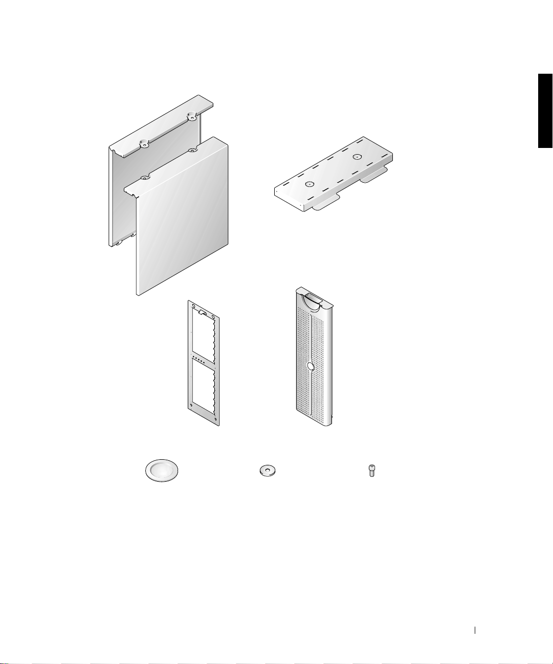
Figure 1-1. Rack-to-Tower Kit Contents
tower left and
right covers
base assembly
tower front panel
round covers (2)
tower bezel, system badge
assembly, and keylock
¼ x 1 x 0.08-inch
washers (4)
¼-20 x 0.5-inch hex
socket-head screws (4)
Rack-to-Tower Conversion Guide 1-3
Page 6

Before You Begin
Before you begin removing your system from the rack and converting it to a tower system,
carefully read “Safety Instructions.”
Removing the Rack Doors
See the procedures for removing doors in the documentation provided with your rack
cabinet.
Recommended Tools and Supplies
www.dell.com | support.dell.com
The following tools are required to perform the conversion:
• A #2 Phillips screwdriver
• A 3/16-inch hex-head (Allen) wrench
• A Torx T-10 driver (for removing and installing the front panels)
Conversion Tasks
Removing a system from the rack and removing the RapidRails™ or VersaRails™ rack
mounting hardware from the rack cabinet includes the following tasks:
• Removing the rack doors
• Removing the system from the rack
• Removing the front panel
• Installi n g th e to w er fr o n t pa n e l
• Installing the base, covers, and bezel
• Removing the RapidRails or VersaRails mounting rail assemblies
• Replacing the rack doors
1-4 Rack-to-Tower Conversion Guide
Page 7
Removing the Rack Doors
You must remove the doors from the rack cabinet to pro vide a ccess to the interior of the
rack and to prevent damage to the doors.
For Dell rack cabinets, see the documentation provided with the rack for instructions on
removing rack doors.
Removing the System From the Rack
CAUTION: If you are removing m ore than one sys tem from the rac k cabinet,
remove the highest of the systems first. Complete the removal of the first
system from the rack before starting the second. Never extend more than one
system from the rack at a time.
WA RNING: Removing a system from a position high up in the rack cabinet
requires up to four people and might require a sturd y, elevated platform on
which to stand. A mechanical lifting platform or similar equipment of the proper
capacity might also be useful. If you attempt to remove and lower the system
without enough people to safely perform the task, you risk personal injury to
yourself and others and damage to the system.
1 Shut down and turn off the system.
See the Installation and Troubleshooting Guide for instructions.
2 Disconnect the cables and power cord from the back of the system.
3 Loosen the thumbscrews that secure the front panel to the front vertical rails (at the
front of the rack cabinet).
4 Using two or more persons, grasp the system at each front handle and slide the system
out of the rack mounting rails (see Figure 1-2).
5 Place the system on a smooth work surface.
Position the system so that the front panel extends 2.54 centimeters (1 inch) beyond
the edge of the table or work surface.
Rack-to-Tower Conversion Guide 1-5
Page 8

Figure 1-2. Removing the System From the Mounting Rail Assemblies
www.dell.com | support.dell.com
thumbscrew
Removing the Front Panel
This procedure is best performed with the front of the system extending 2.54 centimeters
(1 inch) beyond the edge of the work surfac e or ta ble.
1 Label and remove the hard drives from the system.
NOTE: Although not necessary for the conversion, you might want to remove the two
power supply and cooling modules at the back of the system chassis to reduce the weight of
the chassis while you are performing this and the following procedures. See the
and Troubleshooting Guide
2 Remove the 14 T-10 Torx screws that secure the front panel to the chassis.
3 Pull the front panel away from the system chassis, using care to avoid damaging the
five plastic light pipes that extend through the front panel (see Figure1-3).
1-6 Rack-to-Tower Conversion Guide
Installation
for instructions on removing and replacing the modules.
Page 9
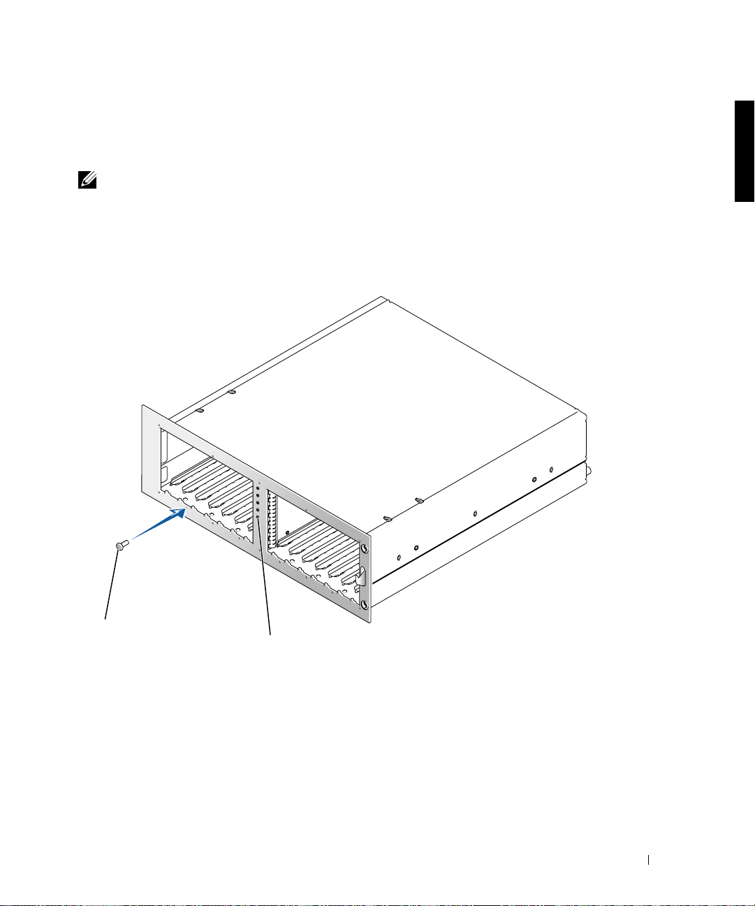
Installing the Tower Front Panel
1 Position the tower front panel in place on the system chassis, using care to install the
five light pipes in their holes in the front panel.
NOTE: In the next step, start all 14 T-10 T orx screws in their holes before tightening any of the
screws to ensure proper alignment.
Install the tower front panel on the chassis, securing it with the 14 T-10 Torx screws
2
that you removed in step 2 of the last procedure, “Removing the Front Panel.”
Figure 1-3. Installing the Tower Front Panel
screws (14)
light pipes (5)
Rack-to-Tower Conversion Guide 1-7
Page 10

Installing the Base, Covers, and Bezel
1 To install the base:
a Position the base assembly and align the two holes on its underside with the two
threaded holes on the right side (the base) of the chassis (see Figure1-4).
b Secure the two hex-socket-head screws and flat washers to the base using a
3/16-inch hex (Allen) wrench.
2 To replace the system right and left covers:
a Raise the system into the tower position, resting on its base.
b Position the covers on their respective sides of the chassis 12.7 millimeters
www.dell.com | support.dell.com
(0.5 inch) behind the front panel.
Tabs on the bottom of each cover should drop into slots in the base assembly.
c Slide the covers toward the front panel until two holes on the top of the cover
align with two threaded holes in the system chassi s.
d Use a 3/16-inch hex (Allen) wrench to secure the two hex-socket-head screws and
flat washers into the two holes at the top of the system .
e Install round covers over the screws you just installed (see Figure 1-4).
1-8 Rack-to-Tower Conversion Guide
Page 11
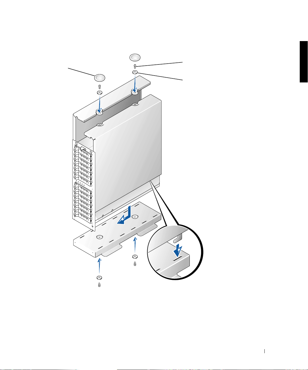
Figure 1-4. Installing the Tower System Cover
round covers (2)
¼-20 x 0.5-inch hexsocket-head screws (4)
¼ x 1 x 0.08-inch flat
washers (4)
Rack-to-Tower Conversion Guide 1-9
Page 12
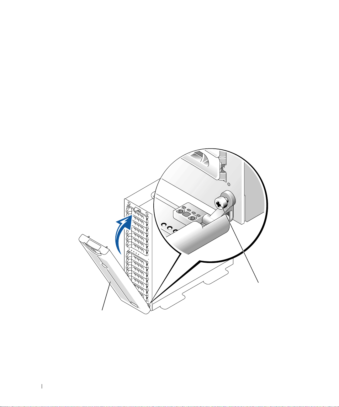
3 To install the bezel:
a Position the bezel so it is perpendicular to the system.
b Install the two captive thumbscrews in their holes at the bottom of the front
panel.
c Reinstall the hard drives and power and cooling modules, if they were removed
(see the Installat i on and Troubleshoot in g G ui de for instructions).
d Close the bezel.
See the Installation and Troubleshooting Guide for information about installing and
configuring your system.
www.dell.com | support.dell.com
Figure 1-5. Installing the Tower Front Bezel
thumbscrew
bezel
1-10 Rack-to-Tower Conversion Guide
Page 13
Removing the RapidRails Mounting Rails
NOTE: If you have VersaRails mounting rails in your rack cabinet, skip to the procedure,
“Removing the VersaRails Mounting Rails.”
At the front of the rack cabinet, locate the blue release push button on one of the
1
RapidRails mounting rail’s mounting-bracket flanges (see Figure 1-6).
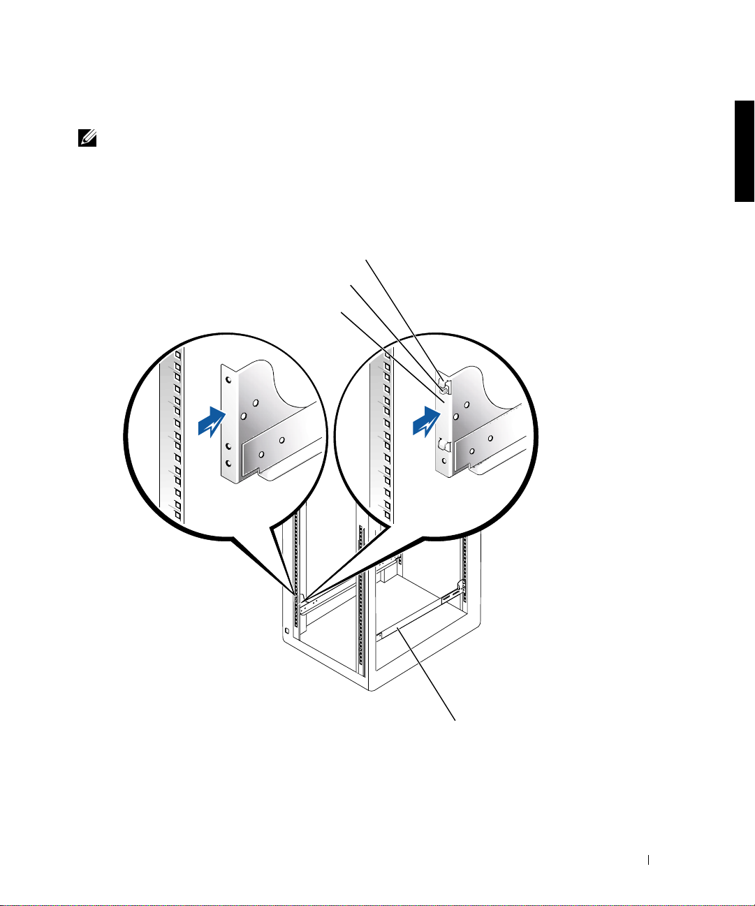
Figure 1-6. Removing the Mounting Rails
mounting hooks
blue release push button
rail mounting-bracket flange
VersaRails
RapidRails
front of rack
mounting rails (2)
Rack-to-Tower Conversion Guide 1-11
Page 14

2 From the front of th e rack ca bi net , pr e ss in on the blue release pu sh but to n, grasp the
rail and lift up, and push the slide assembly back 2.54 centimeters (1 inch) away from
the front vertical rail until the mounting-bracket flange and its mounting hooks
disengage from the square holes in the front vertical rail (see Figure 1-6).
3 Repeat step 2 at the back of the cabinet for this mounting rail .
4 Repeat steps 1 through 3 for the remaining mounting rail on the other side of the rack.
5 Place the mounting rails and all fastener hardware in a box. Label the box as a rack
installation kit for the system model you removed from the rack.
This completes the procedure for removing the RapidRails mounting rails from a rack.
www.dell.com | support.dell.com
Removing the VersaRails Mounting Rails
1 At the front of the rack cabinet, remove the two 10-32 x 0.5-inch Phillips screws on
one of the VersaRails mounting-bracket flanges (see Figure 1-6).
2 Push back on the front mounting-flange bracket 2.54 centimeters (1 inch).
3 At the back of the rack cabinet, remove the two 10-32 x 0.5-inch Phillips screws that
secure the rear mounting-bracket flange to the rack’s vertical rail.
4 Repeat steps 1 through 3 for the remaining mounting rail on t he other side of t he rack.
5 Place the mounting rails and all fastener hardware in a box. Label the box as a rack
installation kit for the system model you removed from the rack.
This completes the procedure for removing the VersaRails mounting rails from a rack.
Replacing the Rack Doors
See the procedures for replacing doors in the documentation provided with your Dell rack
cabinets.
This completes the tower conversion of your system.
1-12 Rack-to-Tower Conversion Guide
Page 15

Systèmes Dell™
Guide de conversion de rack en tour
www.dell.com | support.dell.com
Page 16
Remarques, mises en gardes et avertissements
REMARQUE : UNE REMARQUE indique une information importante destinée à vous aider à
mieux utiliser votre ordinateur.
MISE EN GARDE : UNE MISE EN GARDE indique un dommage potentiel pouvant survenir
(ou une perte de données) et vous dit comment éviter le problème.
ATTENTION : Le message ATTENTION indique une situation potentiellement
dangereuse qui, si elle n'est pas évitée, peut prov oquer une blessure mineure ou
modérée.
AVERTISSEMENT : Le message AVERTISSEMENT indique une situation
potentiellement da ngereus e qui, s i elle n'est pas évitée, peut p rovoquer une
blessure mineure ou modérée.
Les informations fourni es dans ce guide sont susceptibles d'être modifiées sans préavi s.
© 2001 Dell Computer Corporation. Tous droits réservés.
La reproduction de ce document de quelque manière que ce soit sans l'autorisation écrite de Dell Computer Corporation
est strictement inte rdite.
Marques déposées utilisées dans ce guide :
de Dell Computer Corporation.
Toutes les autres marques déposées et noms de marques utili sés dans ce doc um e nt se rapp orte nt aux soci été s
propriétaires des marques et des noms de ces produits. Dell Computer Corporation décline tout intérêt dans l'utilisation
des marques déposées et des noms de marques ne lui appartenant pas.
Septembre 2001 Réf. 2H982 Rév. A01
Dell
, le logo
DELL R apidR ails
et
VersaRails
sont des marques commerciales
Page 17

Ce guide de conversion contient des instructions destinées aux techniciens de maintenance
qualifiés et explique comment retirer un ou plusieurs systèmes Dell™
d’une armoire rack
pour les convertir en version tour ou de bureau. Un kit de conversion de rack en tour est
nécessaire pour chacun des systèmes à convertir.
ATTENTION : Votre système peut être extrêmement lourd lorsqu'il est
entièrement chargé. Pour éviter toute blessure, ne tentez pas d e le déplac er
seul.
Instructions de sécurité
Respectez les consignes de sécurité de ce guide pour assurer votre sécurité personnelle et
pour contribuer à protéger votre serveur, votre système de stockage ou appareil, des
dommages potentiels. Pour obtenir toutes les informations de sécurité, réglementair es et les
garanties, reportez-vous au document intitulé Informations système.
Précautions à suivre concernant les produits destinés à être montés dans des
racks
Pour la stabilité du rack et pour votre sécurité, veuillez respecter les précautions suivantes.
Reportez-vous également à la documentation accompagnant le système et le rack pour
connaître les avertissements et/ou les mises en garde et les procédures spécifiques.
Les serveurs, les systèmes de stockage et les appareils sont considérés comme les
composants d'un rack. Ainsi, le terme "composant" fait référence à tout serveur, tout
système de stockage ou appareil, aussi bien qu'aux différents périphériques ou matériels.
AV ERTISSEMENT : L'instal lation de composants d' un système Dell dans un rack
sans placer de stabilisateu rs avant e t latéraux p eut provoquer l e bascul ement du
rack, et générer des bl essures potenti elles dans certaines si tuations. C'e st
pourquoi il faut toujours installer les stabilisateurs avant d'installer les
composants du rack.
AVERTISSEMENT : Après avoir in stall é le système/ les compos ants dans un rack,
ne tirez jamais plus d'un com posant du rac k sur les support s coulissant s. Le
poids représenté par plus d'un composant étendu po urrait en effet prov oquer le
basculement du rack et blesser l'utilisateur.
REMARQUE : Votre système Dell est certifié sur le plan de la sécurité en tant qu'unité
autonome et en tant que composan t destiné à ê tre utilisé da ns u ne armoire rack Dell , à l'aid e du
kit de rack client de Dell. L'installation du système et du kit de rack Dell dans un rack d'une
autre marq u e n' a r e ç u au cu n e ho mologation de s o rg a nis m e s de c e rt if ic ation de la s éc u ri t é. I l e s t
de votre entière responsabilité de faire évaluer par un organisme de sécurité agréé la
combinaison finale du système et du kit de rack Dell dans un rack d'une autre marque. Dell
décline toute responsabilité et toutes garanties liées à ce type de combinaisons.
Guide de conversion de rack en tour 2-1
Page 18

• Ne déplacez pas seul les racks volumineux. En raison de la hauteur et du poids du rack,
Dell recommande que cette tâche soit réalisée par deux personnes au minimum.
• Avant de travailler sur le rack, as sur ez-vous que les stabi lisateurs s ont bien en place sur
le rack et au sol, et que tout le poids du rack repose sur le sol. Installez les
stabilisateurs avant et latéraux (pour un rack simple) ou les stabilisateurs avant (pour
les racks multiples) avant de travailler sur le rack.
• Chargez toujours le rack du bas vers le haut, en plaçant toujours la plus forte charge en
premier.
• Assurez-vous que le rack est bien de niveau avant de sortir l'un des compo sants à l'ai de
des supports coulissants.
www.dell.com | support.dell.com
• Agissez avec précaution lorsque vous appuyez sur les verrous des rails pour les libérer
et faire glisser un composant hors ou dans le rack. Les rails coulissants pourraient en
effet vous coincer les doigts.
• Après avoir inséré un composant dans le rack, étendez le rail en position maximum
jusqu'à son verrouillage puis faites glisser le composant dans le rack.
• Ne surchargez pas le circuit d'alimentation c.a. dérivé alimentant le rack en électricité.
La charge totale du rack ne doit pas excéder 80 % de la puissance du circuit dérivé.
• Assurez-vous que l'air circule suffisamment entre les composants du rack.
• Ne montez jamais sur l'un des composants du système lors de l'entretien.
Contenu du kit de conversion de rack en tour
Le kit de conversion de rack en tour comprend les éléments suivants (voir la figure 2-1) :
• Un cache de tour, avec verrou et clés
• Un panneau frontal de tour
• Un capot latéral gauche
• Un capot latéral droit
• La base de la tour
• Quatre vis à tête cylindrique à 6 pans ¼-20 x 0,5 pouces
• Quatre rondelles plates ¼ x 1 x 0,08 pouces
• Deux capuchons ronds
2-2 Guide de conversion de rack en tour
Page 19
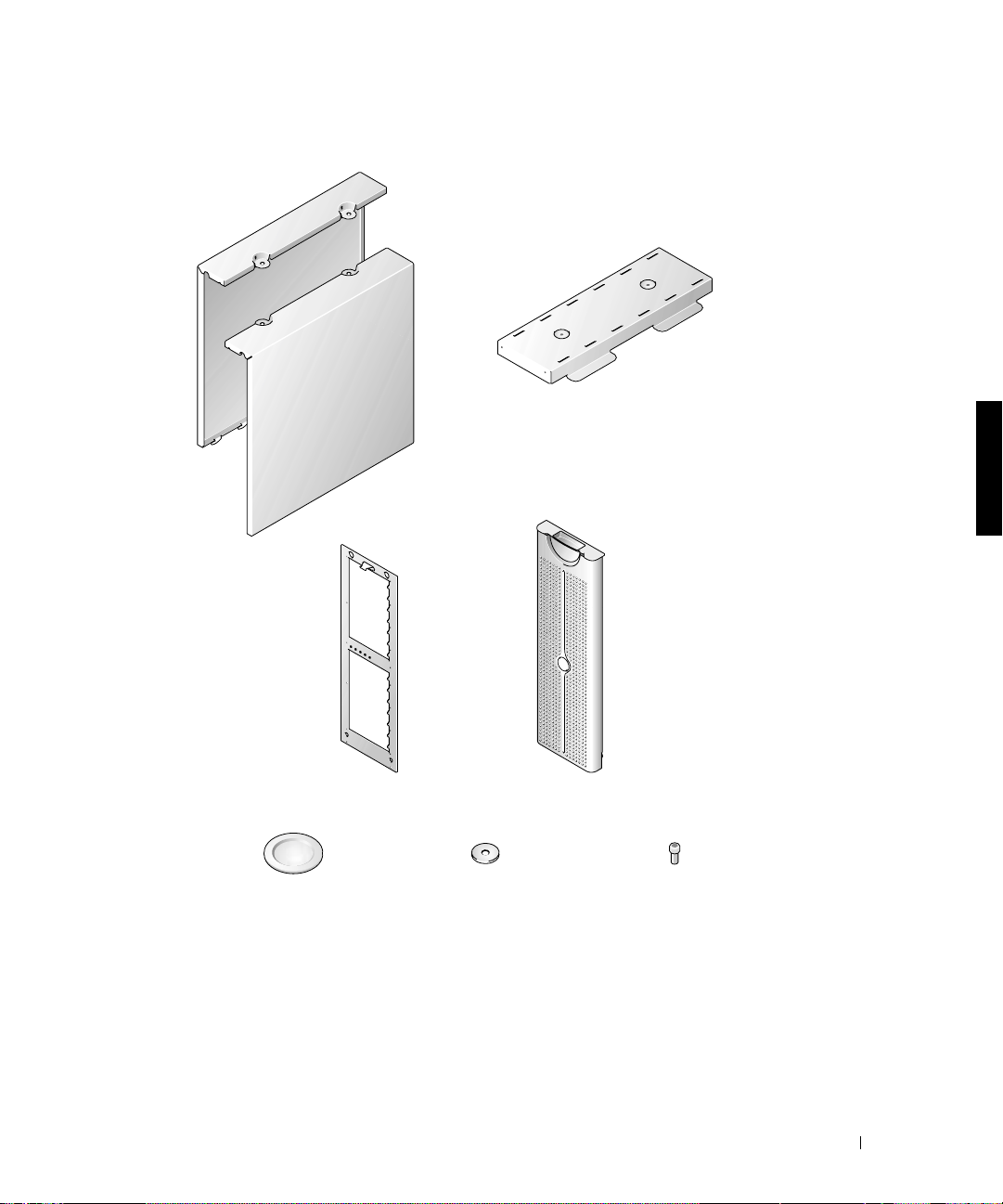
Figure 2-1. Contenu du kit de conversion de rack en tour
base
capots gauche et
droit
panneau frontal de tour
capuchons ronds (2)
cache de la tour, base du
système et verrou
rondelles ¼ x 1 x
0,08 pouces
(4)
Guide de conversion de rack en tour 2-3
vis à tête cylindrique à 6
pans ¼-20 x 0,5 pouces (4)
Page 20

Avant de commencer
Avant de retirer le système du rack pour le convertir en tour, lisez attentivement les
“Instructions de sécurité”.
Retrait des portes du rack
Reportez-vous aux procédures de retrait des portes dans la documentation fournie avec le
rack.
Outils et fournitures re c o m mandés
www.dell.com | support.dell.com
Vous devez utiliser les outils suivants pour effectuer la conversion :
• Un tournevis Phillips n°2
• Une clé mâle (Allen) 3/16 pouces
• Un tournevis Torx T-10 (pour le retrait et l’installation des panneaux avant)
Opérations de conversion
Pour retirer un système de son rack ainsi que le support de montage en rack des rails
RapidRails™ ou VersaRails™, procédez comme suit :
• Retrait des portes du rack
• Retrait du système du rack
• Retrait du panneau frontal
• Installation du panneau frontal de la tour
• Installation de la base, des capots et du cache
• Retrait des rails de montage RapidRails ou VersaRails
• Remise en place des portes du rack
2-4 Guide de conversion de rack en tour
Page 21

Retrait des portes du rack
Vous devez retirer les portes de l'armoire rack pour pouvoir accéder à l'intérieur du rack et
éviter d'endommager les portes.
Pour les armoires racks Dell, reportez-vous aux instructions de retrait des portes figurant
dans la documentation fournie avec le rack.
Retrait du système du rack
ATTENTION : Si vous retirez plusieurs systèmes de l’armoire rack, retirez le
système se trouvant sur la première étagère. Terminez le retrait du premier
système avant de retirer le second. Ne retirez jamais plusieurs système s
simultanément.
AVERTISSEMENT : Le retrait d’un système du premier rack de l’armoire
nécessite quatre person nes et éventuell ement un marchepie d solide ou
l’équivalent. Une plate-forme de levage mécanique ou l’équiv alent peut être
également nécessaire. Si vou s essayez de retirer le sy stème et de l’ abaisser sans
l’aide d’un nombr e suf fis an t de p er sonn es, vo us, et le s a utre s per son nes , r isqu ez
de vous blesser et d’endommager le système.
1 Arrêtez le système et mettez-le hors tension.
Consultez le Guide d'installation et de dépannage pour plus d'instructions.
2 Débranchez les câbles et le cordon d'alimentation à l'arrière du système.
3 Desserrez les vis de fixation assujetiss ant le panneau frontal aux rails verticaux av ant (à
l’avant de l’armoire rack).
4 En vous faisant aider de deux autres personnes ou plus, sais issez chaque poignée avant
du système et faites coulisser ce dernier hors des rails de montage du rack (voir la
Figure 2-2).
5 Placez le système sur une surface plane.
Positionnez le système de façon à ce que le panneau avant dépasse d'environ 2,54
centimètres (1 pouce) du rebord de la table ou de la surface de travail.
Guide de conversion de rack en tour 2-5
Page 22
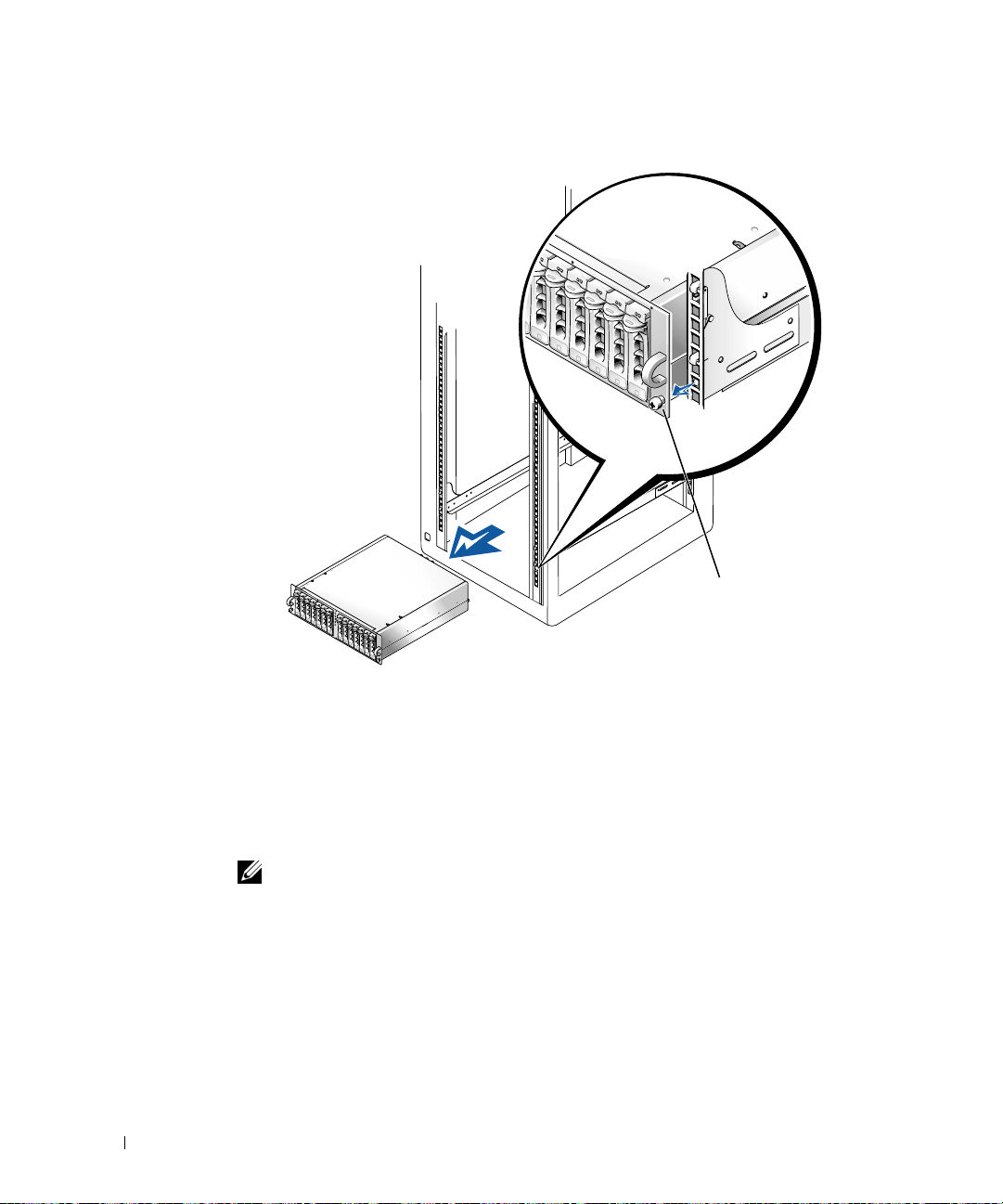
Figure 2-2. Retrait du système des rails de montage
www.dell.com | support.dell.com
vis molette
Retrait du panneau frontal
Pour exécuter cette procédure, il es préférable de placer le système de façon à ce que sa
partie avant dépasse d'environ 2,54 centimètres (1pouce) du rebord de la table ou de la
surface de travail.
1 Etiquetez et retirez les disqu es durs du système.
REMARQUE : Bien que cela ne soit pas indispensable pour effectuer la conversion, vous
pouvez retirer les deux modules d'alimentation et de ventilation à l'arrière du châssis du
système afin de réduire le poids du châssis pendant l'exécution de cette procédure et des
procédures suivantes. Pour savoir comment retirer et remettre en place les modules,
reportez-vous au
2 Retirez les 14 vis T-10 Torx fixant le panneau frontal au châssis.
3 Retirez le panneau frontal du châssis du système, en veillant à éviter d'endommager les
cinq témoins lumineux en plastique qui passent par le panneau frontal (voir la
Figure 2-3).
2-6 Guide de conversion de rack en tour
Guide d'installation et de dépannage
.
Page 23

Installation du panneau frontal de la tour
1 Positionnez le panneau frontal de la tour sur le châssis du système, en veillant à
engager les cinq témoins lumineux dans leurs orifices correspondant dans le panneau
frontal.
REMARQUE : Ensuite, introduisez les 14 vis T-10 Torx dans leurs trous avant de les visser,
afin d'être certain qu'elles sont correctement alignées.
Installez le panneau frontal de la tour sur le châssis, en le fixant à l'aide des vis 14 T-10
2
Torx que vous avez retirées lors de l'étape 2 de la dernière procédure, “Retrait du
panneau frontal”.
Figure 2-3. Installation du panneau frontal de la tour
vis (14)
témoins lumineux (5)
Guide de conversion de rack en tour 2-7
Page 24

Installation de la base, des capots et du cache
1 Pour installer la base :
a Positionnez la base et alignez les deux trous du dessous sur les deux trous filetés
du côté droit (base) du châssis (voir la Figure2-4).
b Fixez les deux vis à tête cylindrique à 6 pans et les rondelles plates à l'aide d'une
clé mâle (Al len) 3/16-pouces.
2 Pour remettre en place les capots droit et gauche du système :
a Replacez le système en position tour, en le faisant reposer sur sa base.
b Positionnez les capots sur leurs côtés respectifs du châssis, à 12,7 millimètres
www.dell.com | support.dell.com
(0,5 pouces) derrière le panneau frontal.
Les pattes situées sous chaque capot doivent s'engager dans les fentes de la base.
c Faites glisser les capots vers le panneau frontal jusqu'à ce que le deux trous sur le
haut du capot s'alignent sur les deux trous filetés du châssis système.
d A l'aide d'une clé mâle 3/16 (Allen), fix ez les deux vis à tête cylindrique à 6 pans et
les rondelles plates dans les deux trous sur le haut du système.
e Recouvrez ces vis avec les capuchons rond s (voir la Figure 2-4 ).
2-8 Guide de conversion de rack en tour
Page 25

Figure 2-4. Installation du capot du système en tour
capuchons
ronds (2)
Vis à tête cylindrique à 6
pans ¼-20 x 0,5 pouces (4)
Rondelles ¼ x 1 x 0,08
pouces (4)
Guide de conversion de rack en tour 2-9
Page 26

3 Pour installer le cache :
a Positionnez le cache afin qu'il soit perpendiculaire au système.
b Installez les deux vis à molette captives dans leurs trous en bas du panneau
frontal.
c Réinstallez les disques durs et le s module s d'a lime ntat ion et de ventilation si vous
les aviez retirés (reportez-vous au Guide d'installation et de dépanna ge pour savoir
comment procéder).
d Fermez le cache.
Reportez-vous au Guide d'installation et de dépannage pour savoir comment installer
et configurer le système.
www.dell.com | support.dell.com
Figure 2-5. Installation du cache avant de la tour
cache
2-10 Guide de conversion de rack en tour
vis molette
Page 27

Retrait des rails de montage RapidRails
REMARQUE : Si votre rack est équipé de rails de montage VersaRails, passez directement à la
procédure intitulée “Retrait des rails de montage VersaRails”.
A l’avant du rack, repérez le loquet bleu figurant sur l’une des brides du support de
1
fixation des rails de montage RapidRails (voir la figure 2-6).
Figure 2-6. Retrait des rails de montage RapidRails
crochets de fixation
loquet bleu
bride de fixation du sup po r t de mo ntage du rail
VersaRails
avant du rack
RapidRails
rails de montage (2)
Guide de conversion de rack en tour 2-11
Page 28

2 A l’avant du rack, appuyez sur le loquet bleu, saisissez le rail et soulevez-le, puis
poussez le support coulissant en arrière d'environ 2,54 cm (1 pouce) pour l'écarter du
rail vertical frontal et dégager la bride de fixation du support de montage et ses
crochets des trous carrés du rail vertical avant (voir la figure 2-6).
3 Répétez les opérations de l’étape 2 à l’arrière du rack pour ce rail de montage.
4 Répétez les opérations des étapes 1 à 3 pour le rail de montage restant de l'autre côté
du rack.
5 Placez les rails de montage et toutes les fixations dans un carton. Placez une étiquette
sur le carton indiquant qu’il s’agit du kit d’installation du modèle de système que vous
avez retiré du rack.
www.dell.com | support.dell.com
La procédure de retrait des rails de montage RapidRails du rack est maintenant
terminée.
Retrait des rails de montage VersaRails
1 A l'avant du rack, retirez les deux vis à tête Phillips 10-32 x 0,5 pouces sur l'une des
brides de fixation du support de montage des rails VersaRails (voir la Figure 2-6).
2 Repoussez en arrière la bride de fixation avant d'environ 2,54 cm (1 pouce).
3 A l'arrière du rack, retirez les deux vis à tête Phillips 10-32 x 0,5 pouces qui
assujetissent la bride de fixation arrière au rail vertical du rack.
4 Répétez les opérations des étapes 1 à 3 pour le rail de montage restant de l'autre côté
du rack.
5 Placez les rails de montage et toutes les fixations dans un carton. Placez une étiquette
sur le carton indiquant qu’il s’agit du kit d’installation du modèle de système que vous
avez retiré du rack.
La procédure de retrait des rails de montage VersaRails du rack est maintenant
terminée.
Réinstallation des portes du rack
Reportez-vous aux procédures de réinstallation des portes dans la documentation fournie
avec le rack Dell.
La conversion en tour de votre système est terminée.
2-12 Guide de conversion de rack en tour
Page 29

Dell™-Systeme
Konvertieranleitung Rack-nach-Tower
www.dell.com | support.dell.com
Page 30

Anmerkungen, Hinweise, Vorsichtshinweise und
Warnungen
HINWEIS: Ein HINWEIS enthält wichtige Informationen, mit deren Hilfe Sie Ihren Computer
besser nutzen können.
BITTE BEACHTEN: BITTE BEACHTEN weist auf eine mögliche Beschädigung von Hardware
oder den Verlust von Daten hin und beschreibt, wie di eses Problem vermieden werden kann.
VORSICHT: Die Angabe VORSICHT warnt vor einer möglicherweise gefährlichen
Situation, die bei Ni chtbeachten zu l eichten oder mittelschweren Schä den führen
kann.
WARNUNG: Eine WARNUNG warnt vor einer möglicherweise gefährlichen
Situation, die bei Ni chtbeachten zu s chweren Verletzungen führen kan n.
Die in diesem Dokument enthaltenen Informationen können ohne Vorankündigung geändert werden.
© 2001 Dell Computer Corporation. Alle Rechte vorbehalten.
Eine Reproduktion dieses Dokuments in jeglicher Form ist nur mit vorheriger schrif tl iche r Gene hm i gung der Dell
Computer Corporation er la ubt .
Die in diesem Text verwendeten Warenzeichen:
der Dell Computer Corporation.
Andere in diesem Dokument möglicherw ei se ve rwendete Warenzeichen und Handelsbezei chnungen sind unter
Umständen Marken und Namen der entsprechenden Firmen oder ihrer Produkte. Die Dell Computer Corporation erhebt
keinen Anspruch auf Warenzeichen oder Handelsnamen mit Ausnahme ihrer eigenen.
September 2001 P/N 2H982 Rev. A01
Dell
, das
DELL
-Logo,
RapidRails
und
VersaRails
sind
Warenzeichen
Page 31

Diese Konvertierungsanleitung enthält Anweisungen für geschulte Se rvice-Techniker zum
-
Entfernen eines oder mehrerer Dell™
Systeme aus einem Gestellschrank und der
Konvertierung zu einem T owersystem. Bei der K onvertierung eines Gestellsystems zu einem
Towersystem benötigen Sie für jedes System, das Sie konvertieren möchten, ein eigenes
Konvertier-Kit Rack-nach-Tower.
VORSICHT: Das System kann sehr schwer sein, wenn es vollständig geladen ist.
Um Verletzungen zu vermeiden, versuchen Sie nicht, das System allein zu
bewegen.
Sicherheitshinweise
Beachten Sie die nachfolgenden Sicherheitshinweise, um Ihre eigene Sicherheit zu
gewährleisten und Schäden an Ihrem Server, Speichersystem oder Ihren Geräten zu
vermeiden. Vollständige Informationen über die Sicherheitsanforderungen, Vorschriften
und Garantiebedingungen finden Sie in Ihren Systeminformationen.
Vorsichtsmaßnahmen für Rack-monti erbare Produkte
Um die Stabilität und Sicherheit des Racks zu gewährleisten, befolgen Sie bitte die
folgenden Vorsichtsmaßnahmen. Spezielle Warnungen und/oder Sicherheitshinweise und
Prozeduren finden Sie auch in der zum System gehörenden Dokumentation zur RackInstallation.
Server, Speichersysteme und Geräte werden als Komponenten in einem Rack betrachtet.
Der Begriff „Komponente“ bezieht sich also auf einen beliebigen Server, ein Speichersystem
oder ein Gerät, sowie auf verschiedene Peripheriegeräte oder Zusatzhardware.
WARNUNG: Werden Dell-Systemkompo nenten in einem De ll-Rack ohne d ie
vorderen und seitli chen Stab ilisatoren i nstalliert, kann da s Rack umkippe n, was
unter bestimmten Bedingung en zu Verletzungen führen kann. Installie ren Sie
daher immer erst die Stabil isatoren, bevor Sie Komponenten im Rack
installieren.
WA RNUNG: Ziehen Sie nach der Install ation von Systemen/ Komponenten in
einem Rack niemals mehr als eine Komponente gleichzeitig auf ihren
Gleitschienen aus dem Rack. Durch das Gewicht von mehr als einer Komponente
kann das Rack umkippen und Verletzungen hervorrufen.
HINWEIS: Ihr Dell-System ist als frei stehende Einheit und für die Verwendung als
Komponente in Dell-Gestellschränken sicherheits-zertifiziert, wobei das Dell Customer Rack Kit
eingesetzt werden muss. Die Installation Ih res Systems und Rack-Kits in Gestellschränken
anderer Hersteller wurde von keiner Prüfbehörde untersucht. Es liegt in Ihrer Verantwortung,
die Eignung der endgültigen Kombination von Dell-Systemen und Rack-Kits für den Einsatz in
Gestellschränken anderer Hersteller durch eine zert ifizierte Prüfbehörde untersuchen zu lassen.
Dell lehnt jede Haftung und Gewährleistung für solche Kombinationen ab.
Konvertieranleitung Rack-nach-Tower 3-1
Page 32

• Bewegen Sie große Racks nicht alleine. Wegen der Höhe und des Gewichtes des Racks
empfiehlt Dell, diese Arbeit mit mindestens zwei Leuten durchzuführen.
• Bevor Sie an einem Rack arbeiten, vergewissern Sie sich, dass die Stab ilis at oren sicher
am Rack befestigt sind, bis auf den Boden reichen und dass das gesamte Gewicht des
Racks auf dem Boden lastet. Installieren Sie an einem einzelnen Rack vordere und
seitliche Stabilisatoren oder an mehreren miteinander verbundenen Racks vordere
Stabilisatoren, bevor Sie an dem Rack arbeiten.
• Belasten Sie das Rack immer von unten nach oben, und bauen Sie die schwerste
Komponente zuerst im Rack ein.
• Vergewissern Sie sich, dass das Rack eben und stabil steht, bevor Sie eine Komponente
www.dell.com | support.dell.com
aus dem Rack ziehen.
• Seien Sie vorsichtig, wenn Sie auf die Verriegelung der Schiene der Komponente
drücken und eine Komponente in das Rack schieben oder aus dem Rack ziehen, da Sie
sich in den Gleitschienen die Finger klemmen können.
• Nachdem eine Komponente in das Rack eingesetzt ist, ziehen Sie die Schienen
vorsichtig bis in die Verriegelungsposition, und schieben Sie dann die Komponente in
das Rack.
• Überlasten Sie nicht den Wechselstromkreis, über den das Rack mit Strom versorgt
wird. Die Gesamtlast des Racks sollte 80 Prozent der Nennbelastbarkeit des
Stromkreises nicht überschreiten.
• Stellen Sie sicher, dass eine ausreichende Luftzufuhr zu den Komponenten im Rack
gewährleistet ist.
• Treten Sie nicht auf ein System / eine Komponente und stellen Sie sich nicht darauf,
wenn Sie an anderen Systemen/Komponenten in einem Rack Arbeiten durchführen.
Inhalt des Rack-nach-Tower-Kit
Das Rack-nach-Tower-Kit enthält die folgenden Komponenten (siehe Abbildung 3-1):
• Eine Tower-Blende, einschließlich Verschluss und Schlüsseln
• Eine Tower-Frontplatte
• Eine Tower-Verkleidung links
• Eine To wer-Verkleidung rechts
• Ein Tower-Sockelmontagesatz
• Vier ¼-20 x 0,5-Zoll Sechskant-Kreuzschlitzschrauben
3-2 Konvertieranleitung Rack-nach-Tower
Page 33

• Vier ¼ x 1 x 0,08-Zoll Unterlegscheiben
• Zwei runde Abdeckungen
Abbildung 3-1. Inhalt des Rack-nach-Tower-Kit
Sockelmontagesatz
TowerVerkleidungen
links und rechts
Tower-Frontplatte
runde
Abdeckungen (2)
Tower-Blende, Syst e m ab z ei ch e n
und Verschluss
¼ x 1 x 0,08-Zoll
Unterlegscheiben (4)
Konvertieranleitung Rack-nach-Tower 3-3
¼-20 x 0,5-Zoll SechskantKreuzschlitzschrauben (4)
Page 34

Bevor Sie beginnen
Bevor Sie Ihr System aus dem Rack entfernen und es zu einem Tow er-System umwandeln,
lesen Sie sorgfältig die „Sicherheitshinweise“.
Entfernen der Rack-Türen
Siehe Vorgehensweise zum Entfernen der Türen in der Dokumentation Ihres
Gestellschranks.
Empfohlene Werkzeuge und Zubehör
www.dell.com | support.dell.com
Für die Konvertierung benötigen Sie die folgenden Werkzeuge:
• Einen Kreuzschlitz-Schraubendreher Nr. 2
• Einen 3/16-Zoll Sechskantstiftschlüssel (Allen)
• Einen Schraubendreher Torx T-10 (zum Entfernen und Wiederanbringen der
Frontplatten)
Konvertierungsschritte
Zum Entfernen eines Systems aus dem Rack und dem Entfernen der RapidRails™ oder
VersaRails™ Rack-Montage-Hardware aus dem Gestellschrank gehören folgende Schritte:
• Entfernen der Rack-Türen
• Entfernen des Systems aus dem Rack
• Entfernen der Frontplatte
•Einbau der Tower-Frontplatte
• Installieren des Sockels, der Abdeckungen und Blende
• Entfernen der RapidRails- oder VersaRails-Montageschienensätze
• Austauschen der Rack-Türen
3-4 Konvertieranleitung Rack-nach-Tower
Page 35

Entfernen der Rack-Türen
Sie müssen die Türen vom Gestellschrank abnehmen, um Zugang zum Inneren des Racks
zu erlangen und Schäden an den Türen zu vermeiden.
Zum Entfernen der Türen in Dell-Gestellschränken siehe Dokumentation des Racks.
Entfernen des Systems aus dem Rack
VORSICHT: Falls Sie mehr als ein System aus dem Gestellschrank entfernen,
beginnen Sie mit dem obers ten System. Entfernen Sie d as erste System
vollständig aus dem Rack, bevor Sie mit dem zweiten beginne n. Ziehen Sie
niemals mehr als ein System g leichzeitig aus dem Rack.
WARNUNG: Wenn Sie ein System aus einer d er oberen Positionen im
Gestellschrank entfernen, benötigen Sie dazu bis zu vier Personen und even tuell
eine solide, erhöhte Plattform , auf der Sie stehen können. Ei ne mechanische
Hebebühne oder eine ähnliche Vorrichtung mit der entsprechenden Belastbarkeit
könnte ebenfalls hil freich sein . Falls Sie das System nicht mit genügend
Personen für eine sichere Durchführung der Aufgabe entfernen, riskieren Sie,
dass Sie und Andere verlet zt werden und das Sys tem beschädigt wi rd.
Fahren Sie das System herunter und schalten Sie es aus.
1
Anweisungen hierzu finden Sie in der Anleitung zur Installation und Fehlersuche Ihres
Systems.
2 Ziehen Sie die Kabel und das Stromkabel von der Rückseite des Systemgehäuses ab.
3 Lösen Sie die Flügelschrauben, mit denen die Frontplatte an den vorderen vertikalen
Schienen (auf der Vorderseite des Gestellschranks) befestigt ist.
4 Heben Sie das System mit zwei oder mehr Personen an jedem vorderen Handgriff an,
und schieben Sie es aus den Rack-Montageschienen (siehe Abbildung 3-2).
5 Legen Sie das System auf eine glatte Arbeit soberflä che.
Positionieren Sie das System so, dass die Frontplatte 2,54 Zentimeter über die Kante
des Tisches oder der Arbeitsoberfläche hinausragt.
Konvertieranleitung Rack-nach-Tower 3-5
Page 36

Abbildung 3-2. Entnehmen des Systems aus den
Montageschienensätzen
www.dell.com | support.dell.com
Flügelschraube
Entfernen der Frontplatte
Dieser Vorgang wird am besten durchgeführt, wenn die Vorderseite des Systems 2,54
Zentimeter über die Kante der Arbeitsoberfläche oder des Tisches hinausragt.
1 Beschriften und entnehmen Sie die Festplatten aus dem System.
HINWEIS: Auch wenn die für die Konvertierung nicht erforderlich ist, entfernen Sie die
zwei Stromversorgungs - und Kühlmodule von der Rückseite des Systemgehäuses, um das
Gewicht des Gehäuses zu reduzieren, während Sie diesen und die folgenden Arbeitsschritte
ausführen. Anweisungen zum Entfernen und Ersetzen der Module fi nden Sie in der
Anleitung zur Installation und Fehlersuche
2 Entfernen Sie die 14 T-10 Torx-Schrauben, mit denen die Frontplatte am Gehäuse
befestigt ist.
3 Heben Sie die Frontplatte vom Systemgehäuse ab und achten Sie dabei darauf, die
fünf Hohllichtleiter aus Kunststoff, die durch die Frontplatte laufen, nicht zu
beschädigen (siehe Abbildung 3-3).
3-6 Konvertieranleitung Rack-nach-Tower
.
Page 37

Installation der Tower-Frontplatte
1 Positionieren Sie die Tower-Frontplatte auf dem Systemgehäuse, und achten Sie
darauf, die fünf Hohllichtleiter durch die Löcher der Frontplatte zu führen.
HINWEIS: Im nächsten Schritt schrauben Sie alle 14 T-10 Torx-Schrauben leicht in die
jeweiligen Löcher, bevor Sie diese festziehen, um eine ordnungsgemäße Abdeckung
sicherzustellen.
2
Befestigen Sie die Tower-Frontplatte auf dem Gehäuse mit den 14 T-10 TorxSchrauben, die Sie in Schritt 2 des letzten Arbeitssgangs „Entfernen der Frontplatte“
entfernt haben.
Abbildung 3-3. Installation der Tower-Frontplatte
Schrauben (14)
Leitungen (5)
Konvertieranleitung Rack-nach-Tower 3-7
Page 38

Installieren des Sockels, der Abdeckungen und Blende
1 So installieren Sie den Sockel:
a Positionieren Sie den Sockelmontagesatz und richten Sie die zwei Löcher auf
dessen Unterseite an den zwei Gewindelöchern auf der rechten Seite (dem
Sockel) des Gehäuses aus (siehe Abbildung3-4).
b Befestigen Sie die zwei Sechskant-Kreuzschlitzschrauben und Unterlegscheiben
am Sockel mit Hilfe eines 3/16-Sechskantstiftschlüssels (Allen).
2 So ersetzen Sie die rechten und linken Verkleidungen des Systems:
www.dell.com | support.dell.com
a Heben Sie das System in Tower-Position, auf seinem Sockel stehend.
b Positionieren Sie die Verkleidungen auf der entsprechenden Seite des Gehäuses
12,7 Millimeter hinter der Frontplatte.
Zungen auf der Unterseite jeder Verkleidung sollten in entsprechenden
Öffnungen des Sockelmontagesatzes einrasten.
c Schieben Sie die Verkleidungen in Richtung Frontplatte, bis die zwei Löcher auf
der Oberseite der Verkleidung an den zwei Gewindelöchern des Systemgehäuses
ausgerichtet sind.
d Verwenden Sie einen 3/16-Zoll Sechskantstiftschlüssel (Allen), um die zwei
Sechskant-Kreuzschlitzschrauben und Unterlegscheiben in den zwei Löchern auf
der Oberseite des Systems zu befestigen.
e Befestigen Sie runde Abdeckungen über den soeben installierten Schrauben
(siehe Abbildung 3-4).
3-8 Konvertieranleitung Rack-nach-Tower
Page 39

Abbildung 3-4. Installation der Tower-Systemabdeckung
runde
Abdeckunge n (2 )
¼-20 x 0,5-Zo ll SechskantKreuzschlitzschrauben (4)
¼ x 1 x 0,08-Zoll
Unterlegscheiben (4)
Konvertieranleitung Rack-nach-Tower 3-9
Page 40

3 So installieren Sie die Blende:
a Positionieren Sie die Blende so, dass sie senkrecht zum System steht.
b Befestigen Sie die zwei selbstsichernden Flügelschrauben in ihren Löchern auf der
Unterseite der Frontplatte.
c Reinstallieren Sie die Festpl atten sowie Stromzufuhr- und Kühlmodule, wenn
diese entfernt wurden (siehe Anleitung zur Installation und Fehlersuche).
d Schließen Sie die Blende.
Weitere Informationen zur Installation und Konfiguration Ihre s Systems finden Sie in
der Anleitung zur Installation und Fehlersuche.
www.dell.com | support.dell.com
Abbildung 3-5. Installation der Tower-Frontblende
Flügelschraube
Blende
3-10 Konvertieranleitung Rack-nach-Tower
Page 41

Entfernen der RapidRails-Montageschienen
HINWEIS: Wenn Ihr Gestellschrank über VersaRails-Montageschienen verfüg t, gehen Sie
direkt zum Arbeitsschritt „Entfernen der VersaRails-Montageschienensätze“.
Suchen Sie auf der Vor derseite des Gestellschranks den blauen Entriegelungsknopf auf
1
einem der Montagehalterungs-Flansche der Montageschienen (siehe Abbildung 3-6).
Abbildung 3-6. Entfernen der Montageschienen
Montagehaken
Blauer Entrie gelungsknopf
Flansch der Schienen-Montagehalterung
VersaRails
Rack-Vorderseite
RapidRails
Montageschienen (2)
Konvertieranleitung Rack-nach-Tower 3-11
Page 42

2 Drücken Sie von der Vorderseite des Gestellschranks her auf den blauen
Entriegelungsknopf, heben Sie die Gleitschienen an und drücken Sie sie ca. 2,54 cm
von der vorderen vertikalen Schiene ab, bis sich der Flansch der Montagehalterung
und seine Montagehaken aus den rechtektigen Löchern in der vertikalen Schiene lösen
(siehe Abbildung 3-6).
3 Wiederholen Sie Schritt 2 auf der Rückseite des Schranks für die dortigen
Montageschienen.
4 Wiederholen Sie die Schritte 1 bis 3 für die verbleibenden Montageschienen auf der
anderen Seite des Racks.
5 Legen Sie die Montageschienen und alle Befestigungs-Hardware in eine Kiste.
www.dell.com | support.dell.com
Beschriften Sie die Kiste als Rack-Installations-Kit des Systemmodells, das Sie aus
dem Rack entfernt haben.
Damit ist der Vorgang zum Entfernen der RapidRails-Montageschienen von einem
Rack abgeschlossen.
Entfernen der V ersaRails-Montageschienen
1 Entfernen Sie an der Vorderseite des Gestellschranks die zwei 10-32 x 0,5-Zoll
Kreuzschlitzschrauben an einer der VersaRail-Montagehalterungs-Flansche (siehe
Abbildung 3-6).
2 Schieben Sie die vordere Flansch der Montagehalterung 2,54 cm nach hinten.
3 Entfernen Sie auf der Rückseite des Gestellschranks die zwei 10-32 x 0,5-Zoll
Kreuzschlitzschrauben, die die hintere Flansch der Montagehalterung an der
vertikalen Schiene des Racks befestigen.
4 Wiederholen Sie die Schritte 1 bis 3 für die verbleibenden Montageschienen auf der
anderen Seite des Racks.
5 Legen Sie die Montageschienen und alle Befestigungs-Hardware in eine Kiste.
Beschriften Sie die Kiste als Rack-Installations-Kit des Systemmodells, das Sie aus
dem Rack entfernt haben.
Damit ist der Vorgang zum Entfernen der VersaRails-Montageschienen von einem
Rack abgeschlossen.
Austauschen der Rack-Türen
Siehe Vorgehensweise zum Austauschen der Türen in der Dokumentation Ihres DellGestellschranks.
Damit ist die Tower-Konvertierung Ihres Systems abgeschlossen.
3-12 Konvertieranleitung Rack-nach-Tower
Page 43

Sistemas Dell™
Guía de conversión de rack a torre
www.dell.com | support.dell.com
Page 44

Notas, avisos, precauciones y advertencias
NOTA: una NOTA indica información importante que le ayudará a usar mejor su ordenador.
AVISO: un AVISO indica un posible daño en el hardware o la pérdida de datos, e informa de
cómo evitar el problema.
PRECAUCIÓN: un m ensaje de PRECAUCIÓ N señala una situaci ón potenci almente
peligrosa que, de no evitarse, pued e provocar lesiones l eves o moderad as.
ADVERTENCIA: una ADVERTENCIA indica una situ ació n poten cialm ente pel igros a
que, si no se evita, puede producir les iones graves.
La información de este documento está sujeta a modificaciones sin previo aviso.
© 2001 Dell Computer Corporation. Reservados tod os los de rechos.
Queda prohibida su reprodu cció n en cu al qui er m edio sin la autorización por escrito de Del l Com puter Corporation.
Marcas comerciales que aparecen en el texto:
comerciales de Dell Computer Co rporat io n.
En este documento pueden utilizarse otras marcas y nombres comerciales para referirse a las entidades propietarias
de dichas marcas y nombres o a sus productos. Dell Computer Corporation renuncia a cualquier derecho sobre las
marcas y nombres comerciales que no sean de su propiedad.
Septiembre de 2001 P/N 2H982 Rev. A01
Dell
, el logotipo de
DELL, RapidRails
y
VersaRails
son marcas
Page 45

Esta guía de conversión ofrece instrucciones para técnicos de servicio experimentados que
deseen desmontar unoo varios sistemas Dell™
de un armario rack y convertir el sistema en
una versión de torre (o de mesa). Es necesario disponer de un kit de conversión de rack a
torre para cada sistema que desee convertir de la versión en rack a la versión de torre.
PRECAUCIÓN: el sis tema pu ede tener u n pes o consi derable total mente ca rgado.
Con el fin de evitar lesiones personales , no intente mover el sistema sin ayuda.
Instrucciones de seguridad
Siga estas directrices de seguridad, con el fin de garantizar su propia seguridad y la del
servidor, sistema de almacenamiento o equipo frente a daños potenciales. Para obtener
información completa acerca de la seguridad, las normas y la garantía, consulte el
documento Información del sistema.
Precauciones para los productos montados en rack
Tenga en cuenta estas precauciones para garantizar la estabilidad y seguridad del rack.
Consulte también la documentación de montaje en rack que se suministra con el sistema y
el rack para conocer las indicaciones y los procedimientos específicos de advertencia y/o
precaución.
Los servidores, sistemas de almacenamiento y equipos se consideran componentes del rack.
Por lo tanto, “componente” se refiere a cualquier servidor, sistema de almacenamiento o
equipo, así como a los distintos periféricos o al hardware de soporte.
ADVERTENCIA: la instalación de componentes de sistemas Dell en un rack Dell
sin los estabilizadores delanteros o laterales mo ntados pu ede hacer que vuelque
el rack, hecho que pu ede l legar a producir lesiones persona les. Por tan to, monte
siempre los estabilizadores antes de montar los compon entes en el rack.
ADV ERTENCIA: de spués de montar los sistemas o compo nentes en un rack,
nunca extraiga más de un componente sobre sus conjuntos deslizantes de forma
simultánea. El peso de más d e un compone nte puede hacer que vuelque el rack y
lesionar a alguien.
NOTA: el sistema Dell está homologado en cuanto a seguridad como unidad autónoma y como
componente para su uso en un armario rack utilizando el kit de rack para clientes de Dell. El
montaje del sistema y kit de rack en armarios rack de otra marca que no sea Dell no ha sido
aprobado por ninguna agencia de seguridad. Es responsabilidad del cliente la evaluación, por
parte de una agencia de seguridad certificada, de la combinación de sistema y kit de rack
montados en armarios rack de otras marcas que no sean Dell. Dell declina toda responsabilidad
y garantías relacion adas con tales combinaciones.
Guía de conversión de rack a torre 4-1
Page 46

• No mueva racks de gran tamaño sin ayuda. Debido a la altura y el peso del rack, Dell
recomienda un mínimo de dos personas para realizar dicha tarea.
• Antes de trabajar en el rack, los estabilizadores deben estar fijados en el rack, deben
llegar al suelo y todo el peso del rack debe descansar sobre el suelo. Asimismo, monte
los estabilizadores delanteros y laterales en un único rack, o los estabilizadores
delanteros para varios racks unidos.
• Cargue siempre el rack desde la parte inferior hacia arriba, colocando en primer lugar
el elemento más pesado.
• El rack debe estar nivelado y estabilizado antes de extraer un componente.
• Tenga cuidado al presionar los pestillos de liberación de las guías de componentes y al
www.dell.com | support.dell.com
extraer o volver a introducir un componente en el rack, puesto que puede pillarse los
dedos con las guías deslizantes.
• Una vez insertado un componente en el rack, extienda con cuidado la guía hasta su
posición de bloqueo y deslice el componente hacia el interior del rack.
• No sobrecargue el ramal del circuito de alimentación de CA que suministra energía al
rack. La carga total del rack no debe ser superior al 80 por ciento del valor nominal del
ramal del circuito.
• Los componentes del rack deben disponer de suficiente circulación de aire.
• No se suba ni se apoye en ningún sistema o componente al reparar otros sistemas o
componentes del rack.
Contenido del kit rack a torre
El kit de conversión de rack a torre consta de los elementos siguientes (consulte la figura 4-1):
• Un bisel de torre, incluida cerradura y llaves
• Un panel frontal para la torre
• Una tapa para el lado izquierdo de la torre
• Una tapa para el lado derecho de la torre
• Una base para la torre
• Cuatro tornillos de cabeza hexagonal con encastro de ¼-20 x 0,5 pulgadas
• Cuatro arandelas planas de ¼ x 1 x 0,08 pulgadas
•Dos tapas redondas
4-2 Guía de conversión de rack a torre
Page 47

Figura 4-1. Contenido del kit de conversión de rack a torre
base
tapas derecha e
izquierda de la
torre
panel frontal de la torre
tapas redondas (2)
bisel de la torre, conjunto de placa de
identificación del sistema y cerradura
arandelas de ¼ x 1
x 0,08 pulgadas
(4)
Cuatro tornillos de cabeza
hexagonal con encast ro de
¼-20 x 0,5 pulgadas (4)
Guía de conversión de rack a torre 4-3
Page 48

Antes de empezar
Antes de comenzar a desmontar el sistema del rack y convertirlo en un sistema de torre , lea
detenidamente las “Instrucciones de seguridad”.
Desmontaje de las puertas del rack
Para retirar las puertas, consulte los procedimientos en la documentación suministrada con
el armario rack.
Herramientas y suministros recomendados
www.dell.com | support.dell.com
Para llevar a cabo la conversión son necesarias las siguientes herramientas:
• Destornillador Phillips del nº 2
• Llave de cabeza hexagonal de 3/16 pulgadas (Allen)
• Llave Torx T-10 (para extraer y montar los paneles frontales)
Tareas de conversión
La extracción de un sistema del rack y la retirada del armario rack del hardware de montaje
en rack RapidRails™ o VersaRails™ incluye las siguientes tareas:
• Desmontaje de las puertas del rack
• Desmontaje del sistema del rack
• Desmontaje del panel frontal
• Montaje del panel frontal de la torre
• Montaje de la base, tapas y bisel
• Desmontaje de las guías de montaje RapidRails o VersaRails
• Colocación de las puertas del rack
4-4 Guía de conversión de rack a torre
Page 49

Desmontaje de las puertas del rack
Debe desmontar las puertas del armario rack para tener acceso al interior del rack y evitar
daños en las mismas.
Para obtener instrucciones sobre cómo desmontar las puertas del rack en armarios rack de
Dell, consulte la documentación suministrada con el rack.
Extracción del sistema del rack
PR ECAUCIÓN: si va a desmontar más de un sistema del armario rack, extraiga
primero el sistema situado en la parte superior. Termine de desmontar el primer
sistema del rack antes de comenzar con el segund o. Nunca extraiga más de un
sistema del rack a la vez.
ADVERTENCIA: Para desmontar un sistema en una po sición elevad a del armari o
son necesarias hasta cuatro pers onas y tal vez necesi te una plata forma eleva da y
resistente donde colocarse. También puede ser útil una plataforma elevadora
mecánica o equipo simila r con la capacidad apropiada. Si intenta extraer o bajar
el sistema sin las personas suficientes para llevar a cabo esta tarea de forma
segura, corre el riesgo de sufrir daños personales o causar daños a otras personas
o al sistema.
Apague el sistema.
1
Consulte la Guía de instalac ión y resolución de pro b lemas para obtener instrucciones.
2 Desconecte los cables de alimentación de la parte posterior del sistema.
3 Afloje los tornillos que sujetan el panel frontal a las guías verticales delanteras (en la
parte frontal del armario rack).
4 Utilizando dos o más personas, agarre el sistema por cada manecilla frontal y extraiga
el sistema de las guías de montaje del rack (consulte la figura 4-2).
5 Coloque el sistema en una superficie de trabajo blanda.
Coloque el sistema de forma que el panel frontal se coloque unos 2,54 centímetros
(1 pulgada) sobrepasando el borde de la mesa o la supe rficie de trabajo.
Guía de conversión de rack a torre 4-5
Page 50

Figura 4-2. Extracción del sistema de las guías deslizantes
www.dell.com | support.dell.com
tornillo de mano
Desmontaje del panel frontal
Este procedimiento se realiza mejor con la parte frontal del sistema extendida 2,54
centímetros (1 pulgada) sobrepasando el borde de la superficie o mesa de trabajo.
1 Etiquete y extraiga las unidades de disco duro del sistema.
NOTA: aunque no es necesario para la conversión, quizás desee retirar los dos módulos de
alimentación y refrigeración de la parte posterior del c hasis del sistema p ara reducir el peso
del chasis mientras realiza este procedimiento y los siguientes. Consulte la
instalación y resolución de problemas
colocación de los módulos.
2
Desmonte los 14 tornillos Torx T-10 que sujetan el panel frontal al chasis.
3 Saque el panel frontal del chasis del sistema, teniendo cuidado para evitar dañar los
cinco tubos de plástico ligeros colocados a lo largo del panel frontal (consulte la
figura 4-3).
4-6 Guía de conversión de rack a torre
Guía de
para obtener instrucciones sobre el desmontaje y
Page 51

Instalación del panel frontal de la torre
1 Coloque el panel frontal de torre en su sitio en el chasis del sistema, y monte con
cuidado los cinco tubos ligeros en sus orificios del panel frontal.
NOTA: en el siguiente paso, coloque todos los tornillos Torx 14 T-10 en sus orificios antes de
apretar ninguno de ellos para asegurar una alineación correcta.
Monte el panel frontal de la torre en el chasis, fi jándolo con los tornillos Torx 14 T-10,
2
quitados en el paso 2 del último procedimiento, “Desmontaje del panel frontal”.
Figura 4-3. Montaje del panel frontal de la torre
tornillos (14)
tubos ligeros (5)
Guía de conversión de rack a torre 4-7
Page 52

Montaje de la base, tapas y bisel
1 Parta instalar la base:
a Coloque la base y alinee los dos orificios en su parte inferior con los dos orificios
roscados en el lado derecho (la base) del chasis (consulte la figura 4-4).
b Fije los dos tornillos he xago nales con encastre en cabeza y las arandelas planas a la
base utilizando una llave hexagonal de 3/16 pulgadas (Allen).
2 Para volver a colocar las tapas derecha e izquierda del sistema:
a Levante el sistema en la posición de torre, dejando que descanse sobre su base.
b Coloque las tapas en sus respectivos lados del chasis 12,7 milímetros
www.dell.com | support.dell.com
(0,5 pulgadas) detrás del panel frontal.
Las lengüetas de la parte inferior de cada tapa deben introducirse en las ranuras de
la base.
c Deslice las tapas hacia el panel frontal hasta que los dos or ificios de la parte
superior de la tapa se alineen con los dos orificios roscados del chasis del sistema.
d Utilice una llave hexagonal de 3/16 pulgadas (Allen) para fijar los dos tornillos
hexagonales con encastr e en cabe za y la s arandelas planas en los dos orific ios de la
parte superior del sistema.
e Monte las tapas redondas sobre los tornillos que acaba de fijar (consulte la figura
4-4).
4-8 Guía de conversión de rack a torre
Page 53

Figura 4-4. Montaje de la tapa del sistema de torre
tapas redondas (2)
cuatro tornillos de cabeza
hexagonal con encastro de
¼-20 x 0,5 pulgadas (4)
arandelas de ¼ x 1 x 0,08
pulgadas (4)
Guía de conversión de rack a torre 4-9
Page 54

3 Para montar el bisel:
a Coloque el bisel de forma que esté perpendicular al sistema.
b Monte los dos tornillos de mano integrados en sus orificios situados en la parte
inferior del panel frontal.
c Vuelva a montar las unidades de disco duro y los módulos de alimentación y
refrigeración, si se han desmontado (consulte la Guía de instalación y resolución de
problemas para obtener instrucciones).
d Cierr e el bisel.
Consulte la Guía de instalación y resolución de problemas para obtener información
sobre el montaje y configuración del sistema.
www.dell.com | support.dell.com
Figura 4-5. Montaje del bisel frontal de la torre
bisel
4-10 Guía de conversión de rack a torre
tornillo de mano
Page 55

Desmontaje de las guías de montaje RapidRails
NOTA: si tiene las guías de montaje VersaRails en el armario rack, pase directamente al
procedimiento “Desmontaje de las guías de montaje VersaRails”.
En la parte frontal del armario rack, localice el botón de liberación azul situado en una
1
de las bridas del soporte de montaje de las guías de montaje RapidRails (consulte la
figura 4-6).
Figura 4-6. Desmontaje de las guías de montaje
ganchos de montaje
botón de liberación azul
brida del soporte de montaje de la guía
VersaRails
parte delantera del rack
RapidRails
guías de montaje (2)
Guía de conversión de rack a torre 4-11
Page 56

2 Desde la parte frontal del armario rack, presione en el botón de liberación azul, agarre
la guía y levántela, tire del conjunto deslizante hacia atrás aproximadamente 2,54
centímetros (1 pulgada) para separarlo de la guía vertical delantera hasta que la brida
del soporte de montaje y sus ganchos de montaje se separen de los orificios cuadrados
de la guía vertical delantera (consulte la figura 4-6).
3 Repita el paso 2 en la parte posterior del armario para esta guí a de montaje.
4 Repita los pasos del 1 al 3 para la guía de montaje del otro lateral del rack.
5 Coloque las guías de montaje y todo el material de sujeción en una caja. Coloque una
etiqueta en la caja indicando que se trata de un kit de instalación en rack para el
modelo del sistema que ha desmontado del rack.
www.dell.com | support.dell.com
Con esto se completa el procedimiento para desmontar las guías de monta je
RapidRails de un rack.
Desmontaje de las guías de montaje VersaRails
1 En la parte frontal del armario rack, retire los dos tornillos Phillips de 10-32 x 0,5
pulgadas en una de las bridas del soporte de montaje VersaRails (consulte la figura 4-6).
2 Empuje hacia atrás el soporte de la brida de montaje frontal 2,54 centímetros
(1 pulgada).
3 En la parte posterior del armario rack, quite los dos tornillos Phillips de 10-32 x 0,5
pulgadas que fijan la brida del soporte de montaje posterior a la guía vertical del rack.
4 Repita los pasos del 1 al 3 para la guía de montaje del otro lateral del rack.
5 Coloque las guías de montaje y todo el material de sujeción en una caja. Coloque una
etiqueta en la caja indicando que se trata de un kit de instalación en rack para el
modelo del sistema que ha desmontado del rack.
Con esto se completa el procedimiento para desmontar las guías de monta je
VersaRails de un rack.
Colocación de las puertas del rack
Consulte los procedimientos para volver a colocar las puertas en la documentación
suministrada con el armario rack de Dell.
La conversión en torre de su sistema ya está terminada.
4-12 Guía de conversión de rack a torre
Page 57

Dell™ システム
ラック - タワー転換ガイド
www.dell.com | support.dell.com
Page 58

メモ、注意、警告および危険
メモ : メモは、コンピュータを使いやすくする為の重要な情報を説明しています。
注意 : 注意は、ハードウェアの損傷やデータの損失の可能性があることを示し、その危険
を回避するための方法を説明しています。
警告 : 警告は、問題を回避しないと、身体に危険を及ぼす可能性があることを示します。
危険 : 危険は、問題を回避しないと、身体に重大な損害を与える可能性や死に至る危険性
があることを示します。
ここに記載されている内容は予告なく変更されることがあります。
© 2001 年すべての著作権は Dell Computer Corporation にあります。
Dell Computer Corporation の書面による許可のない複写は、いかなる形態においても厳重に禁じられています。
本書で使用されている商標について:Dell、DELL のロゴ、RapidRails、および Ve r sa R ai l s は Dell Computer
Corporation の商標です。
本書では、必要に応じて上記記載以外の商標および会社名が使用されている場合がありますが、 これらの商
標や会社名は、一切 Dell Computer Corporation に所属するものでは ありません。
2001 年 9 月 P/N 2H982 Rev. A01
Page 59

この転換ガイドは、1 基または複数の Dell
™
システムをラックキャビネットから取り
外し、タワーに転換する際のサービス技術者向けの手 順書です。ラックバージョン
からタワーバージョンに転換するシステム 1 基ごとにラック - タワー転換キット 1
セットが必要です。
警告 : システムの重量は、完全装備時にかなりの重量になります。傷害事故が発生する
のを避けるため、一人でシステムを移動させようとしないでください。
安全にお使いいただくための注意
ご自身の身体の安全を守り、サーバ、ストレージシステム、アプライアンスを損傷
から保護するために、以下の点にご注意ください。安全、規則、保証について詳し
くは、ご利用のシステムの『システム情報』マニュアルを参照してください。
ラックに設置可能な製品に対する注意点
ラックの安定性や安全性に関し て、次の点にご注意ください。特定の警告や注意文
および手順については、システムやラックに同梱されているラック取り付 けマニュ
アルを参照してください。
サーバ、ストレージシステム、およびアプライアンスは、ラックに取り付ける部品
とみなします。したがって「部品」の用語は、サーバ、ストレージシステム、アプ
ライアンス、および各種周辺装置またはサポートハードウェアを意味します。
危険 : ラック正面および横の安定板を取り付けずに Dell のラックに Dell システム部品を
取り付けると、ラックが転倒し、けがをする恐れがあります。したがって、必ず安定板
を取りつけてからラックに部品を取り付けてください。
危険 : ラックにシステム / 部品を取り付けた後は、一度に 2 台以上の部品を、スライドア
センブリのラックから引き出さないでください。重みでラックが転倒し、けがをする恐
れがあります。
メモ : お使いの Dell システムは、独立型のユニットとして、また、Dell カスタマラック
キットで構成される Dell のラックキャビネットに取り付ける部品として、その安全性を
保証されています。Dell 以外のメーカーのラックキャビネットに Dell のシステムやラッ
クキットを取り付けることは、どの安全機関でも承認されていません。Dell 以外のメー
カーのラックキャビネットで Dell のシステムやラックキットを最終的に組み合わせて使
用する場合は、ユーザーが責任を持って 認定安全機関で適合性の評価を受け てくださ
い。Dell は、上記の組み合わせに関する一切の責任および保証を否認します。
• 大型ラックを 1 人で移動しないでください。ラックの高さと重さを考慮して、
少なくとも 2 人以上でラックを移動することをお勧めします。
ラック - タワー転換ガイド 5-1
Page 60

• ラックを移動する前に、安定板がラックに固定されて床面に伸び、ラックの全
重量が床面にかかっていることを確認してください。ラックを移動する前に、1
つのラックの場合は正面と横の安定板、複数の組み合わされたラックの場合は
正面の安定板を取り付けます。
• ラックには必ず下から上の順に、最も重いものから設置します。
• 部品をラックから引き出す前に、ラックが平行で安定していることを確認して
ください。
• 部品レールリリースラッチを押し、部品をラックの中または外にスライドする
場合はご注意ください。スライドレールに指をはさまれることがあります。
www.dell.com | support.dell.com
• 部品をラックに設置したら、レールをロック位置に静かに伸ばし、部品をラッ
クの中にスライドします。
• ラックに電力を送る AC 分岐回路に過重電流を流さないでください。ラックの
総負荷が分岐回路定格の 80 パーセントを超えないようにしてください。
• ラックの部品に空気が充分に送られていることを確認します。
• ラックの他のシステム/部品を取り扱っているときに、システム/部品の上に乗っ
たり、立ってはいけません。
ラック - タワーキットの内容
ラック - タワーキットの内容は、次のとおりです ( 図 5-1 を参照してください )。
• タワーベゼル 1 個 ( キーロックとキーが付属している )。
• タワー正面パネル 1 枚
• タワー左側カバー 1 枚
• タワー右側カバー 1 枚
• タワーベースアセンブリ 1 個
¼-20 x 0.5 インチ六角ソケットヘッドネジ 4 本
•
•
¼ x 1 x 0.08 インチ平ワッシャ 4 個
• 丸カバー 2 枚
5-2 ラック - タワー転換ガイド
Page 61

図 5-1. ラック - タワーキットの内容
タワー左側および
右側カバー
ベースアセンブリ
タワー正面パネル
丸カバー (2)
タワーベゼル、システム
バッジアセンブリ、キーロック
¼ x 1 x 0.08
インチ
ワッシャ (4)
¼-20 x 0.5 インチ六角
ソケットヘッドネジ (4)
ラック - タワー転換ガイド 5-3
Page 62

はじめに
システムをラックから取り外してタワ ーに転換す る作業を始める前に、『安全にお
使いいただくための注意』をお読みください。
ラックの扉の取り外し
ラックキャビネットに同梱のマニュアルに記載されている扉の取り外し手順を参照
してください。
推奨する工具および備品
www.dell.com | support.dell.com
転換を行うには、次の工具が必要です。
•A #2 プラスドライバ
•3/16 インチ六角 ( アレン ) レンチ
• Torx T- 10 ドライバ ( 正面パネルの取り外しおよび取り付け用 )
転換手順
ラックからシステムを取り外す、およびラックキャビネットから R api dRa ils™ または
VersaRails
す。
• ラックの扉を取り外します。
• ラックからシステムを取り外します。
• 正面パネルを取り外します。
• タワー正面パネルを取り付けます。
• ベース、カバー、およびベゼルを取り付けます。
• RapidRails/VersaRails 取り付け用レールアセンブリを取り外します。
• ラックの扉の交換
™
ラック取り付け用ハードウェアを取り外すには、次の手順を実行しま
5-4 ラック - タワー転換ガイド
Page 63

ラックの扉の取り外し
ラック内部で作業を行えるよう にするため、また、ドアに傷が付かないようにする
ため、ラックキャビネットからドアを取り外す必要があります。
Dell ラックキ ャビネットの ラックの扉を取り外す手順に関して は、ラックに同梱の
マニュアルを参照してください。
ラックからのシステムの取り外し
警告 : 複数のシステムをラックキャビネットから取り外す場合は、一番高い位置にある
システムから取り外します。最初のシステムをラックから完全に取り外してから、2 つ
目のシステムを取り外してください。決して 1 度に複数のシステムを ラックから 取り外
さないでください。
危険 : ラックキャビネットの高い位置にあるシステムを取り外すには、最大 4 人の作業
員が必要です。また、頑丈な踏み台が必要な場合がありま す。作業を安全 に実行するた
めに必要な作業員数未満でシステ ムを下 に動か す場合、人がケガ をした り、システムが
損傷する危険があります。
1
システムをシャットダウンして電源を切ります。
手順については、システムの『Installation and Troublesh ooti ng G uide』 を参照して
ください。
2 ケーブルと電源ケーブルをシステムの背面から外します。
3 正面パネルを正面の垂直レール ( ラックキャビネットの正面にあります ) に固定
しているネジを緩めます。
4 2 人以上の作業員で、各正面ハンドルを押さえてシステムをラックから引き出し
ます ( 図 5-2 を参照してください )。
5 システムを平らな作業面に置きます。
システムの位置を合わせると、テーブル / 作業面の端から前面パネルが 2.54cm 手
前に出ます。
ラック - タワー転換ガイド 5-5
Page 64

図 5-2. 取り付け用レールアセンブリからのシステムの取り外し
www.dell.com | support.dell.com
ネジ
正面パネルの取り外し
この手順は、テーブル / 作業面の端から前面パネルが 2.54cm (1 inch) 手前に出ている
場合に適用します。
1 ハードディスクにラベルを貼り付けてシステムから取り外します。
メモ :転換が必要ではない場合でも、システムシャーシの背面で電源および冷却用の
2 個のモジュールを取り外してシャーシの重量を減らする場合には、次の手順を実
行 します。モジュールの取り外しおよび交 換については、『Installation and
Troubleshooting Guid e』を参照してください。
2 正面パネルをシャーシに固定している 14 T-10 Torx ネジを取り外します。
3 正面パネルから突起している 5 つのプラスティックライトパイプを傷つけない
ように注意しながら、システムシャーシから正面パネルを慎重に持ち上げます
( 図 5-3 を参照 )。
5-6 ラック - タワー転換ガイド
Page 65

タワー正面パネルの取り付け
1 タワー正面パネルをシステムシャーシに合わせ、5 つのプラスティックライトパ
イプを慎重に正面パネルの穴に取り付けます。
メモ : 次の手順では、位置を正しく合わせるために、すべての 14 T-10 Torx ネジをネジ穴
に差し込んでから締め付けてください。
2
タワー正面パネルをシャーシに取り付けて、「正面パネルを取り外 す」の手順
2 で取り外した 14 T-10 Torx ネジで固定します。
図 5-3. タワー正面パネルの取り付け
ネジ (14)
ライトパイプ (5)
ラック - タワー転換ガイド 5-7
Page 66

ベース、カバー、およびベゼルの取り付け
1 ベースの取り付け
a ベースアセンブリを合わせて、2 つの穴を裏面にあるシャーシの右側 ( ベー
ス ) のネジ穴に合わせます ( 図 5-4 を参照 )。
b 3/16インチ六角 (アレン) レンチを使用して、2 本の六角ソケットヘッドネジ
と平ワッシャをベースに固定します。
2 システムの左右のカバーを交換するには、次を手順を実行します。
a システムをタ ワーポジションに起こし、ベースの上に置きます。
www.dell.com | support.dell.com
b カバーを、正面パネルから 12.7 ミリ (0.5 インチ ) 後になるように、シャーシ
のそれぞれの側面に合わせます。
各カバーの底部のタブは、ベースアセンブリのスロットにはめ込む必要が
あります。
c カバーの上部 にある 2 つの穴が、システムシャーシのネジ穴に合うまで、カ
バーを正面パネルの方向にスライドさせます。
d 3/16 インチ六角 (アレン) レンチを使用して、2 本の六角ソケットヘッドネジ
と平ワッシャをシステム上部の 2 つの穴に固定します。
e 取り付けたネ ジの上に丸カバーを取り付けます ( 図 5-4 参照 )。
5-8 ラック - タワー転換ガイド
Page 67

図 5-4. タワーシステムカバーの取り付け
丸カバー (2)
¼-20 x 0.5 インチ六角
ソケットヘッドネジ (4)
¼ x 1 x 0.08 インチ
平ワッシャ (4)
ラック - タワー転換ガイド 5-9
Page 68

3 ベゼルを取り付けるには、次の手順を実行します。
a ベゼルをシス テム対して垂直な位置に合わせます。
b 2 本の固定蝶ネジを正面パネルの底部の穴に取り付けます。
c 取り外してあったハードドライブ、電源および冷却モジュールを再度取り
付けます ( 手順については、『Installation and Troubleshooting Guide』を参照
してください )。
d ベゼルを閉じます。
システムのインストールおよび設定については、『Installation and Troubleshooting
Guide』を参照してください。
www.dell.com | support.dell.com
図 5-5. タワー正面ベゼルの取り付け
ベゼル
5-10 ラック - タワー転換ガイド
蝶ネジ
Page 69

RapidRails 取り付け用レールの取り外し
メモ : お使いのラックキャビネットに VersaRails 取り付け用レールが使用されている場
合、このセクションを飛ばして「VersaRails 取り付け用レールの取り外し」へ進んでくだ
さい。
1
ラックキャビネットの正面で、RapidRails 取り付け用ブラケットフランジの 1 つ
についている青のリリース用押しボタンを探します ( 図 5-6 参照 )。
図 5-6. 取り付け用レールの取り外し
取り付けフック
青のリリース用押しボタン
レール取り付け用ブラケットフランジ
VersaRails
ラック前面
RapidRails
取り付け用レール (2)
ラック - タワー転換ガイド 5-11
Page 70

2 ラックキャビネットの正面から、青のリリース用押しボタンを押し込んで持ち
上げ、スライドアセンブリを正面の垂直レールから後方に 2.54cm (1 インチ ) ほ
ど押して、取り付け用ブラケットフランジと取り付け用フックを正面の垂直
レールの四角い穴から外します ( 図 5-6 参照 )。
3 同じ取り付け用レールについて、キャビネットの後方で手順 2 を繰り返します。
4 ラックの反対側のレールで、手順 1 ~ 3 を繰り返します。
5 取り付け用レールおよびすべての 固定用金具を箱に入れます。箱には、ラック
から取り外したシステムモデルのラック取り付けキットとしてラベルを貼りま
す。
www.dell.com | support.dell.com
これで、RapidRails 取り付け用レールをラックから取り外す手順が終了しまし
た。
VersaRails 取り付け用レールの取り外し
1 ラックキャビネットの正面で、一方の VersaRails 取り付け用ブラケットフラン
ジにある 2 本の 10-32 x 0.5 インチのプラスネジを取り外します ( 図 5-6 参照 )。
2 正面の取り付け用フランジブラケットを 2.54cm (1 インチ ) ほど後方に押しま
す。
3 ラックキャビネットの背面で、後の取り付け用ブラケットフランジをラックの
垂直レールに固定している 2 本の 10-32 x 0.5 インチのプラスネジを取り外しま
す ( 図 5-6 参照 )。
4 ラックの反対側のレールで、手順 1 ~ 3 を繰り返します。
5 取り付け用レールおよびすべての 固定用金具を箱に入れます。箱には、ラック
から取り外したシステムモデルのラック取り付けキットとしてラベルを貼りま
す。
これで、VersaRails 取り付け用レールをラックから取り外す手順が終了しました。
ラックの扉を元に戻す
Dell ラックキャビ ネットに同梱のマ ニュアルに記載さ れている扉を元に戻す手順 を
参照してください。
これでお使いのシステムのタワーへの転換は完了です。
5-12 ラック - タワー転換ガイド
Page 71

Page 72

Printed in the U.S.A.
Imprimé aux Etats-Unis.
Gedruckt in U.S.A.
Impreso en EE.UU.
www.dell.com | support.dell.com
P/N 2H982 Rev. A01
 Loading...