

Page 1

Dell PowerVault 220S and 221S Systems Service Manual
Dell™ PowerVault™ 220S and 221S Systems Service
Manual
Preface
System Overview
Basic Troubleshooting
Removing and Replacing Parts
Information in this document is subject to change without notice.
© 2001-2004 Dell Computer Corporation. All rights reserved.
Reproduction in any manner whatsoever without the written permission of Dell Computer Corporation is strictly forbidden.
Trademarks used in this text: Dell, the DELL logo, PowerVault, and Dell OpenManage are trademarks of Dell Computer Corporation; IBM is a
registered trademark of International Business Machines Corporation.
Other trademarks and trade names may be used in this document to refer to either the entities claiming the marks and names or their products.
Dell Computer Corporation disclaims any proprietary interest in trademarks and trade names other than its own.
Initial release: 17 Sep 2001
Last revised: 25 Oct 2004
file:///C|/Users/rishi_sood/Desktop/220s/en/sm/index.htm[3/7/2013 12:09:10 PM]
Page 2
Preface : Dell PowerVault 220S and 221S Systems Service Manual
Back to Contents Page
Preface
Dell™ PowerVault™ 220S and 221S Systems Service Manual
Read This First Notes, Notices, and Cautions
Read This First
Prerequisites for using this manual to service your system is a basic knowledge of IBM®-compatible PCs, prior training in IBM-compatible PC
troubleshooting techniques, and experience troubleshooting SCSI storage enclosures. In addition to this manual and the User's Guide that came
with your system, the Installation and Troubleshooting Guide provides installation and configuration information, including cabling diagrams and
setup procedures. Your array management software documentation provides information on configuring and managing your storage system.
This manual is divided into the following sections:
"System Overview" — Overview of the system's features, components, and technical specifications
"Basic Troubleshooting" — Initial checks and procedures used to solve basic system problems
"Removing and Replacing Parts" — Removal and replacement of all field-replaceable parts, including power supplies, cooling modules,
enclosure management modules (EMM), split-bus modules, and the SCSI backplane
Notes, Notices, and Cautions
Throughout this manual, there may be blocks of text printed in bold type or in italic type. These blocks are notes, notices, and cautions, and
they are used as follows:
NOTE: A NOTE indicates important information that helps you make better use of your computer.
NOTICE: A NOTICE indicates either potential damage to hardware or loss of data and tells you how to avoid the problem.
CAUTION: A CAUTION indicates a potential for property damage, personal injury, or death.
Back to Contents Page
file:///C|/Users/rishi_sood/Desktop/220s/en/sm/preface.htm[3/7/2013 12:09:11 PM]
Page 3
System Overview : Dell PowerVault 220S and 221S Systems Service Manual
Back to Contents Page
System Overview
Dell™ PowerVault™ 220S and 221S Systems Service Manual
Overview Components and Indicators
System Features Technical Specifications
Service Features
Overview
Dell™ PowerVault™ 220S and 221S systems are reliable, flexible, external SCSI expansion enclosures designed to support multiple Dell storage environments and RAID configurations.
Each system offers maximized drive-spindle count, hot-plug hard drives, optional redundant power supplies, redundant cooling modules, rackmount capability, systems management
features, and a modular design for easy upgrades. Most major components, including hard drives and power supply/cooling modules are hot-pluggable and can be removed and replaced
easily. The enclosure management module (EMM), split-bus module, and SCSI terminator card are "warm-pluggable." This means they can be removed or inserted while the power is
on, but all I/O activity has ceased.
This section provides an overview of system features and components, and technical specifications.
System Features
Your system offers the following features:
Tower or rack versions (3 units [U] [19 inches]).
Capacity for fourteen 1-inch hot-plug SCSI hard drives. (See "Technical Specifications" or your system's readme file for supported hard-drive speeds and capacities.)
Universal hard-drive carriers.
Support for a variety of RAID controller cards, host-integrated RAID controllers, and host bus adapter (HBA) cards. (See your system's readme file for supported RAID controllers
and HBA cards.)
Hot-plug power supply and cooling modules that are combined for easy serviceability. The cooling modules are redundant. Power supply modules can be redundant or
nonredundant.
Optional redundant enclosure management modules (EMM).
Support for the following direct-attach configurations:
High-availability redundant EMM configuration in joined-bus mode (with a terminator card for nonredundant configurations).
High-availability cluster configurations (with redundant EMMs) that allow multiple-server access to the same enclosure.
Split-bus module (with redundant EMMs) to operate the enclosure using two separate buses.
Enclosure management through in-band SCSI enclosure services (SES) for power supplies and cooling modules and SCSI-accessed fault-tolerant enclosures (SAFTE).
Storage management through Dell OpenManage™ Array Manager.
Four sensors for monitoring ambient temperatures and shutdown capability when temperatures reach a critical level.
Audible warning for critical component failure.
Supported for all new Dell servers. (See your system's readme file for supported systems.)
file:///C|/Users/rishi_sood/Desktop/220s/en/sm/intro.htm[3/7/2013 12:09:13 PM]
Page 4
System Overview : Dell PowerVault 220S and 221S Systems Service Manual
Service Features
Your storage system was designed for easy serviceability. All hard drives, power supplies, cooling modules, EMMs/SCSI terminator cards, and split-bus modules can be removed and
replaced without having to remove system covers or other components.
Components and Indicators
Front-Panel Components and Indicators
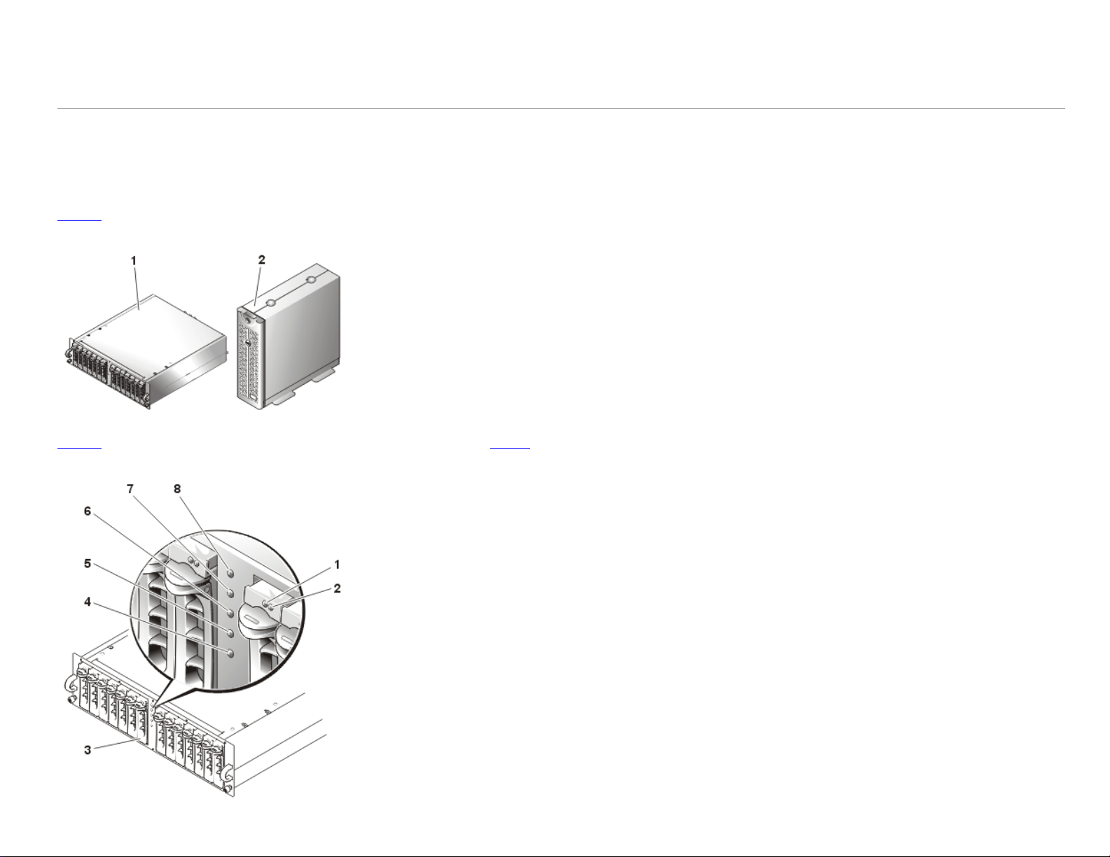
Figure 1 shows the front-view orientation of both systems.
Figure 1. System Orientation
1 PowerVault 220S
2 PowerVault 221S
Figure 2 illustrates LED indicators and components on the system's front panel. Table 1 lists conditions indicated by each LED.
Figure 2. Front-Panel Features
file:///C|/Users/rishi_sood/Desktop/220s/en/sm/intro.htm[3/7/2013 12:09:13 PM]
1 drive busy LED indicator
2 drive status LED indicator
3 hard drives (14)
4 over-temperature LED indicator
5 split-bus LED indicator
6 cluster LED indicator
7 shelf-fault LED indicator
8 power LED indicator
Page 5
System Overview : Dell PowerVault 220S and 221S Systems Service Manual
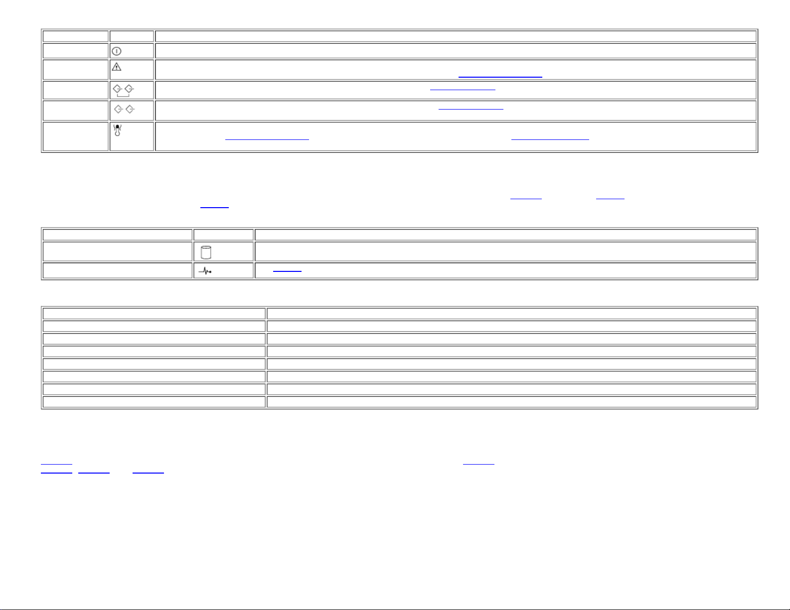
Table 1. Front Panel Indicators
LED Indicator LED Icon Condition
Power (green)
Shelf-fault
(amber)
Cluster (green)
Split-bus
(green)
Overtemperature
(amber)
Hard-Drive Carrier LED Indicators
Each of your storage system's 14 hard-drive carriers has two LED indicators: a busy indicator and a status indicator (see Figure 2 for location). Table 2 shows the hard-drive LED
indicators with the associated LED icons.
Table 2. Hard-Drive Carrier LED Indicators
LED Indicator LED Icon Condition
Busy (green)
Status (green and amber)
Table 3. Hard-Drive Carrier Status Indicator Flash Patterns
Condition Status Indicator Pattern
Slot empty, ready for insert/remove Off
Drive online, prepare for operation Steady green
Drive identify Flashes green four times per second
Prepare for removal Flashes green twice per second at equal intervals
Drive rebuild Flashes green twice per second at unequal intervals
Drive fail Flashes amber four times per second
Predicted failure Flashes green, then amber, then off, repeating this sequence every two seconds
At least one power supply is supplying power to the system.
One of the following conditions has occurred: power-supply failure, EMM failure, cooling-module failure, over-temperature condition, split-bus module not
installed, or firmware currently being downloaded. For more information, see "
The system is configured for cluster mode. For more information, see "Split-Bus Module."
The system is configured for split-bus mode. For more information, see "Split-Bus Module."
An over-temperature condition has occurred (the system will shut down when the temperature inside the box exceeds 50°C [122°F]). For more
information, see "
Basic Troubleshooting." For the locations of the temperature probes, see "Temperature Probes."
Table 3 lists the flash patterns for the hard-drive status indicator.
The hard drive is active on the SCSI bus.NOTE: This LED is controlled by the hard drive.
See Table 3 for flash patterns and conditions.
Basic Troubleshooting."
Back-Panel Features and Indicators
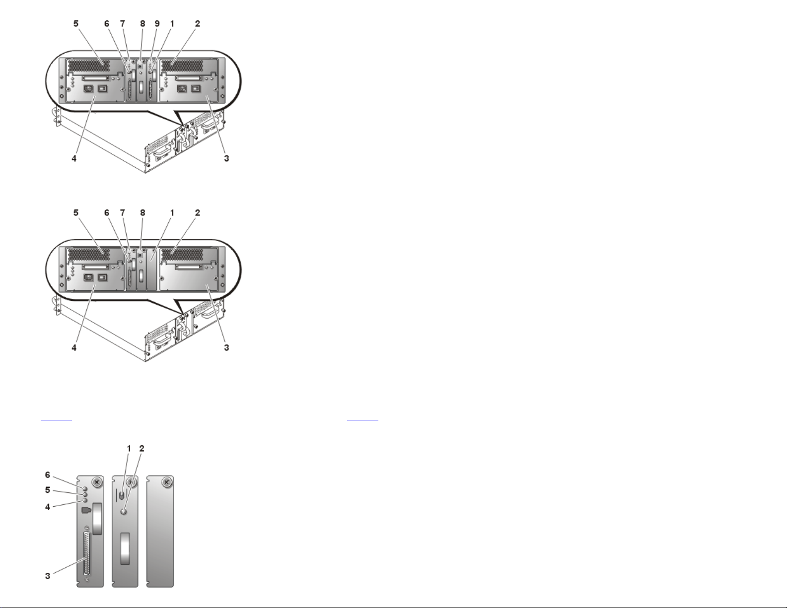
Figure 3 illustrates the back-panel features for systems with redundant EMMs and redundant power supplies. Figure 4 illustrates the back-panel features for nonredundant systems. See
Figure 5, Figure 6, and Figure 8 for more detail on the back-panel indicators.
Figure 3. Back-Panel Features (Systems With Redundant EMMs and Redundant Power Supplies)
file:///C|/Users/rishi_sood/Desktop/220s/en/sm/intro.htm[3/7/2013 12:09:13 PM]
1 unused port
2 cooling module (blowers 2 and 3)
3 power supply (PSU1)
4 power supply (PSU2)
5 cooling module (blowers 0 and 1)
6 unused port
Page 6
System Overview : Dell PowerVault 220S and 221S Systems Service Manual
Figure 4. Back-Panel Features (Systems With Nonredundant EMMs and Nonredundant Power Supplies)
7 primary EMM
8 split-bus module
9 secondary EMM
1 SCSI terminator card
2 cooling module (blowers 2 and 3)
3 power-supply blank
4 power supply
5 cooling module (blowers 0 and 1)
6 unused port
7 EMM
8 split-bus module
Back-Panel Modules
Figure 5 illustrates the features and indicators on the back-panel modules. See Figure 6 for more information about bus configuration switch modes.
Figure 5. Back-Panel Modules Features and Indicators
file:///C|/Users/rishi_sood/Desktop/220s/en/sm/intro.htm[3/7/2013 12:09:13 PM]
1 bus configuration switch
2 power LED indicator
3 SCSI connector
4 active LED indicator
5 fault LED indicator
6 power LED indicator
Page 7
System Overview : Dell PowerVault 220S and 221S Systems Service Manual
Split-Bus Module
Your storage system supports three SCSI bus modes controlled by the split-bus module:
Joined-bus mode
Split-bus mode
Cluster mode
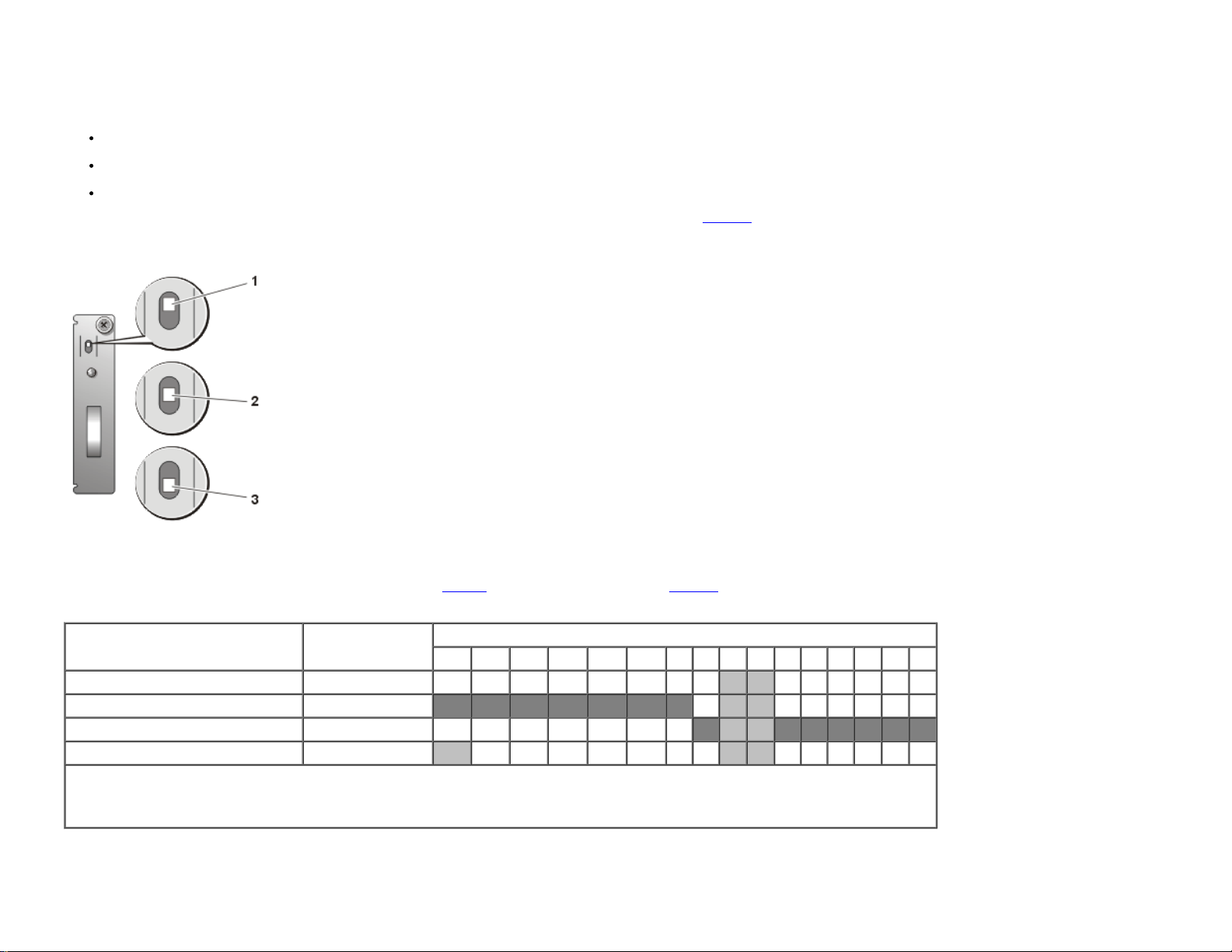
These modes are controlled by the position of the bus configuration switch when the system is turned on.
configuring the SCSI bus modes, see your Installation and Troubleshooting Guide.
Figure 6. Bus Configuration Switch Modes
Figure 6 illustrates the switch position for each mode. For more information on
1 joined-bus mode (top position for rack systems, right for tower systems)
2 split-bus mode (center position for rack and tower systems)
3 cluster mode (bottom position for rack systems, left for tower systems)
The only difference between cluster mode and joined-bus mode is the SCSI ID assigned to the enclosure services processor on the EMM. When cluster mode is detected, the processor
SCSI ID changes from 6 to 15. As a result, SCSI ID 15 is disabled, leaving 13 available hard drives in cluster mode. This allows a second initiator, such as a host bus adapter or RAID
controller card on a second host server, to use SCSI ID 6 (see
Table 4. SCSI ID Assignments
Configuration
Joined-bus 1 H S
Split-bus—primary EMM 1 H S
Split-bus—secondary EMM 1 H S
Cluster 2 S H H
NOTE: The unshaded SCSI IDs are available for hard-drive use as indicated for each configuration. The reserved SCSI IDs are used as follows:
H = used by the host system initiator.
S = used by the storage system SES.
Cables Used SCSI IDs Used
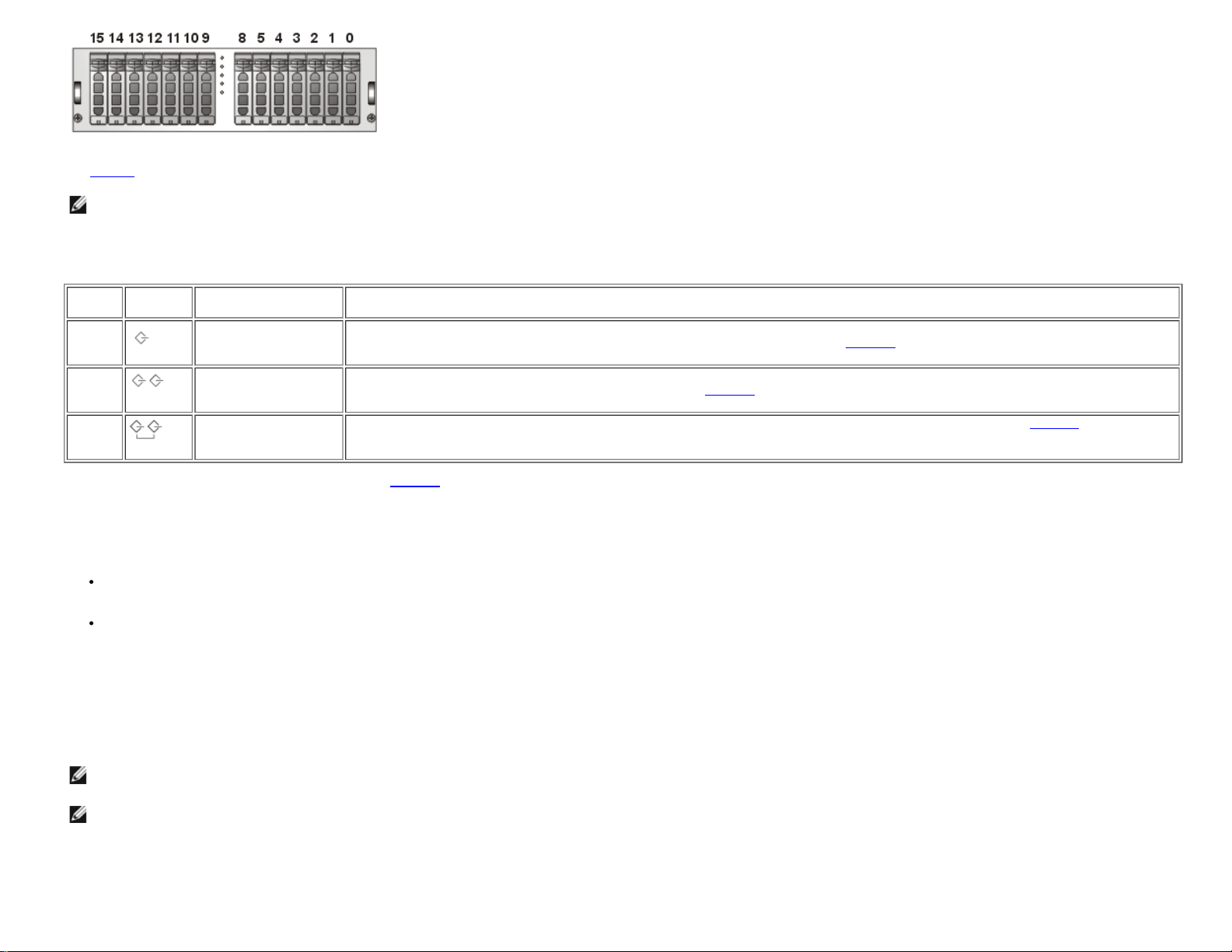
Figure 7. SCSI ID Numbers and Associated Hard Drives
file:///C|/Users/rishi_sood/Desktop/220s/en/sm/intro.htm[3/7/2013 12:09:13 PM]
Table 4 for SCSI ID assignments and Figure 7 for associated hard drives).
15 14 13 12 11 10 9 8 7 6 5 4 3 2 1 0
Page 8
System Overview : Dell PowerVault 220S and 221S Systems Service Manual
See Table 5 for a description of split-bus module modes and functions.
NOTE: To change the SCSI bus mode, you must change the position of the bus configuration switch before turning on the storage system. Changing the position of the bus
configuration switch while the system is on will not affect system operation. If you change the configuration, you must first reboot the host system and then the server storage
system for the changes to take effect. For more information on SCSI bus modes, see your Installation and Troubleshooting Guide.
Table 5. Split-Bus Module Modes
Mode LED Icon Position of Bus
Joinedbus
mode
Splitbus
mode
Cluster
mode
Configuration Switch
Top for rack systems,
right for tower systems
Center for all systems LVD termination on the split-bus module is enabled and the two buses are electrically isolated, resulting in two seven-drive SCSI buses.
Bottom for rack
systems, left for tower
systems
Function
LVD termination on the split-bus module is disabled, electrically joining the two SCSI buses to form one contiguous bus. In this mode,
neither the split-bus nor the cluster LED indicators on the front of the system (see
The split-bus LED indicator on the front of the system (see
LVD termination is disabled and the buses are electrically joined. The cluster LED on the front of the system (see
illuminated while the system is in cluster mode.
Figure 2 for locations) are illuminated.
Figure 2 for location) is illuminated while the system is in split-bus mode.
Figure 2 for location) is
The split-bus module has only one LED indicator (see
Figure 5 for LED location), which is illuminated when the module is receiving power.
Enclosure Management Module (EMM)
The EMM serves two primary functions in your storage system:
SCSI bus expansion — Acts as a buffer for the SCSI bus, electrically dividing the bus into two independent segments while logically allowing all SCSI bus traffic to pass through it
transparently. The buffer improves the quality of the SCSI signals and allows longer cable connections.
Management functions — Includes SES and SAFTE reporting to the host system, control of all system LED indicators, and monitoring of all environmental elements, such as
temperature sensors, cooling modules, and power supplies.
A system with redundant enclosure management features has two EMMs that are designated as primary and secondary that can be configured in either a cluster or joined-bus mode. A
system with nonredundant enclosure management has one EMM and one SCSI terminator card configured in a joined-bus mode or two EMMs configured in a split-bus mode. In
redundant EMM systems, only one EMM per SCSI bus is active at one time, so only one EMM per SCSI bus can respond to SCSI commands from an initiator.
In joined-bus and cluster modes, if a secondary EMM receives a message that the primary EMM has failed, the fault LED indicator on the primary EMM is illuminated and the condition is
reported to the host server. The secondary EMM becomes active and holds the failed primary in a reset state until it is replaced. If the primary EMM detects that the secondary has
failed, the secondary's fault LED indicator is illuminated and the failed status is reported to the host system.
NOTE: In split-bus mode, although each EMM monitors the entire storage system, it controls only half of the hard-drive slots. If one EMM fails in split-bus mode, the second EMM
will report the failure, but will not assume control of the hard-drive slots that were previously controlled by the failed EMM.
NOTE: The EMM is "warm-pluggable." This means it can be removed or inserted while the power is on. However, all I/O activity between the host and the storage system must be
stopped.
The primary EMM is always plugged into the slot on the left (viewed from the back of the system). In systems with redundant EMMs configured for joined-bus mode, the primary EMM
assumes control of all the system's functionality. In addition, the active EMM is the only module that reports status of the system to the host system through SES and SAFTE protocols.
Because the secondary EMM must assume the responsibilities of the primary in the event that the primary fails, both the primary and secondary EMMs are continuously monitoring the
status of the system's components.
file:///C|/Users/rishi_sood/Desktop/220s/en/sm/intro.htm[3/7/2013 12:09:13 PM]
Page 9
System Overview : Dell PowerVault 220S and 221S Systems Service Manual
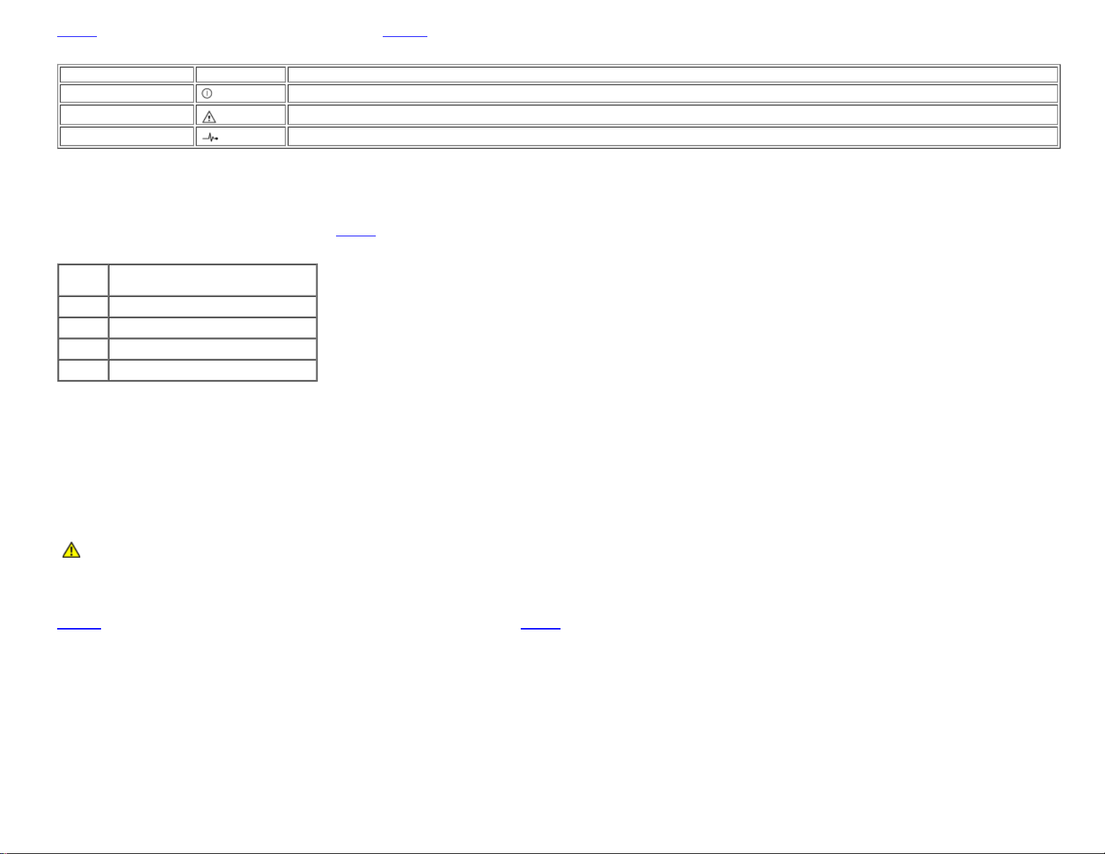
Table 6 lists the conditions for each EMM LED indicator. See Figure 5 for location of the LED indicators.
8 cooling module
Table 6. EMM LED Indicators
LED Indicator LED Icon Condition
Power (green)
Fault (amber)
Active (green)
The system is receiving power.
An EMM has failed.
The EMM is operating normally and performing all the responsibilities of the primary EMM.
Temperature Probes
Your storage system contains four temperature probes that monitor system temperature and shut down the system in the event of overheating. Each EMM and both the primary and
secondary backplanes contain temperature probes.
Table 7. Temperature Probe Locations
Probe Location
Probe 0 Primary EMM
Probe 1 Secondary EMM
Probe 2 Drive backplane behind drive ID #3
Probe 3 Drive backplane behind drive ID #12
Table 7 identifies the location of each probe.
Power Supply/Cooling Modules
Your storage system supports two combined power supply and cooling modules. While the system is designed to operate normally with only one functional power supply, both cooling
modules (each with two blowers) must be present for proper cooling. If only one power supply is needed, a blank must be inserted into the other slot to mount the second cooling
module. In this nonredundant power-supply configuration, the power-supply blank has the capacity to transfer power and control signals to and from the cooling module.
If one blower within a cooling module fails, your storage system reverts to a nonredundant fan configuration. The remaining three blowers in both cooling modules operate at higher
speeds to maintain proper system cooling and produce higher acoustical noise than in the redundant fan configuration (with four blowers in two cooling modules).
CAUTION: A power supply and cooling module can be removed from a powered-on system for a maximum period of five minutes. Beyond that time, the system
begins to overheat, and at a critical temperature, shuts down to prevent damage.
The cooling module is securely mounted to the power supply using a hook-and-latch fastener. This configuration simplifies the removal and installation of cooling modules and power
supplies.
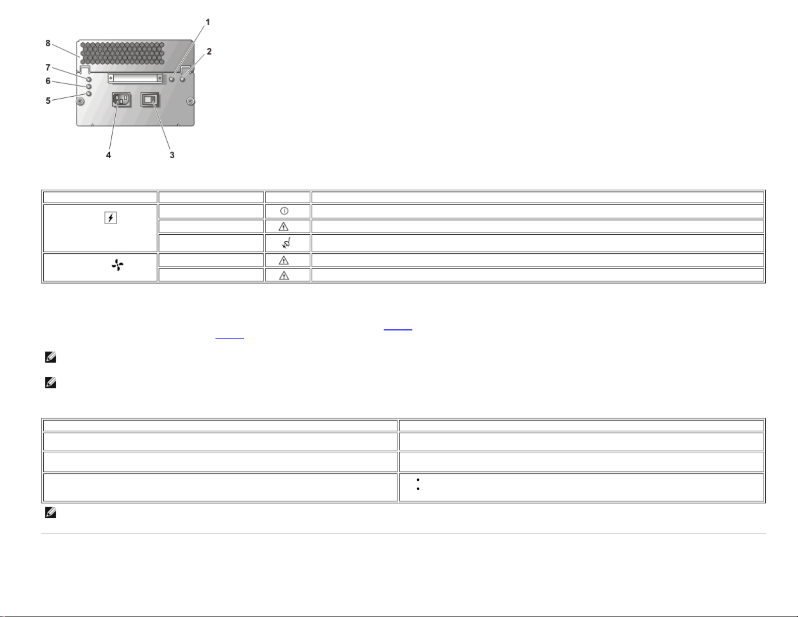
Figure 8 illustrates the power supply and cooling module features and LED indicators. Table 8 lists the function of each power supply and cooling module indicator.
Figure 8. Power Supply and Cooling Module LED Features and Indicators
file:///C|/Users/rishi_sood/Desktop/220s/en/sm/intro.htm[3/7/2013 12:09:13 PM]
1 blower A fault LED indicator
2 blower B fault LED indicator
3 on/off switch
4 AC connector
5 AC status LED indicator
6 fault LED indicator
7 power-on LED indicator
Page 10
System Overview : Dell PowerVault 220S and 221S Systems Service Manual
Table 8. Power Supply and Cooling Module LED Indicators
Module Icon LED Indicator LED Icon Function
Power on (green) DC output voltages are within specifications.
Power supply
Cooling module
Fault (amber) One of the DC output voltages is not within specifications.
AC status (green)
Blower A fault (amber) Cooling module blower A has failed.
Blower B fault (amber)
AC input voltage is within specifications regardless of the position of the power switch.
Cooling module blower B has failed.
Audible Alarm
The primary EMM activates an audible alarm if any of the shelf-fault conditions listed in Table 1 occur. If a critical event occurs, the alarm sounds continuously. If a noncritical event
occurs, the alarm sounds every 10 seconds.
NOTE: The audible alarm is disabled by default. To enable the alarm, you must change the default setting using your array management software. For more information, see your
array management software documentation.
NOTE: When the system is on and a split-bus module is not detected, the audible alarm will sound regardless of whether it is enabled or disabled.
Table 9. Audible Alarm Critical and Noncritical Events
Critical Events Noncritical Events
Two or more cooling-module blowers have failed or a cooling module is not installed. One power supply has failed.
One or more temperature sensors are in critical range (in excess of 50°C [122°F] inside
the box).
The split-bus module is not installed.
NOTE: It is rare for both EMMs to fail simultaneously. However, if this event occurs, the system cannot issue critical or noncritical event alarms for any system component. If both
power supplies fail simultaneously, the system can issue critical or noncritical event alarms only if 5-V power is available.
Table 9 lists critical and noncritical events.
One cooling-module blower has failed.
One or more temperature sensors are in the warning range.
One EMM has failed.
Technical Specifications
file:///C|/Users/rishi_sood/Desktop/220s/en/sm/intro.htm[3/7/2013 12:09:13 PM]
Page 11

System Overview : Dell PowerVault 220S and 221S Systems Service Manual
Drives
Split-bus module 1 LED indicator for power
SCSI hard drives support for up to fourteen 1-inch-by-3.5-inch LVD Ultra 160 and Ultra 320 SCSI hot-plug hard drives, at speeds of 10K
Bus
Configuration support for any of the following:
Back-Panel Connectors
SCSI connector 68-pin shielded P-type SCSI for connection to host
Backplane Board Connectors
or 15K rpm and capacities of 18 GB, 36 GB, 73 GB, 146 GB, or 300 GB
one 14-device SCSI bus (joined-bus mode)
one clustered 13-device SCSI bus (cluster mode)
two independent 7-device SCSI buses (split-bus mode)
SCSI connector 68-pin shielded P-type SCSI for connection to host
Hard drives fourteen 80-pin SCA-2 connectors
Power supply/cooling module 2 high-current connectors
Enclosure management modules (EMM) 210-pin connector
Split-bus module 180-pin connector
Enclosure Modules
EMM 2 warm-pluggable modules with 68-pin shielded P-type SCSI connectors
Split-bus module 1 warm-pluggable module with an external slide switch to change between split-bus, joined-bus, and cluster modes
SCSI terminator card 1 warm-pluggable module to the terminate SCSI bus in nonredundant EMM configurations
LED Indicators
Front panel 5 LED status indicators for power, fault, split bus, cluster mode, and over-temperature
Hard-drive carrier 1 single-color activity LED and 1 two-color LED status indicator per drive
EMM 3 LED status indicators for power, fault, and active status
file:///C|/Users/rishi_sood/Desktop/220s/en/sm/intro.htm[3/7/2013 12:09:13 PM]
Page 12

System Overview : Dell PowerVault 220S and 221S Systems Service Manual
Power supply and cooling module 3 LED status indicators for power supply status, power supply fault, and AC status and 2 for cooling module fault
Power Supplies
Wattage 600 W
Heat dissipation 200 W
Voltage 100–240 V rated (actual 85–264 V)
Frequency 50–60 Hz
Amperage 9.4 A at 100 V, 4.6 A at 200 V
Physical
Height 13.26 cm (5.22 inches)
Width 44.58 cm (17.55 inches)
Depth 50.8 cm (20 inches)
Weight
PowerVault 220S
PowerVault 221S
32.4 kg (71.5 lb) maximum redundant configuration with all hard drives installed
42.2 kg (93.0 lb) maximum redundant configuration with all hard drives installed
Environmental
Temperature:
Operating
Storage
Relative humidity
Operating
Storage
Altitude
Operating
BTU per hour 2750
Available Hard-Drive Power (Per Slot)
Supported hard-drive power consumption up to 1.3 A at +12V
file:///C|/Users/rishi_sood/Desktop/220s/en/sm/intro.htm[3/7/2013 12:09:13 PM]
10° to 35°C (50° to 95°F)
–40° to 65°C (–40° to 149°F)
8% to 80% (noncondensing)
8% to 95% (noncondensing)
–16 to 3048 m (–50 to 10,000 ft)
up to 1.5 A at +5V
Page 13

System Overview : Dell PowerVault 220S and 221S Systems Service Manual
Back to Contents Page
file:///C|/Users/rishi_sood/Desktop/220s/en/sm/intro.htm[3/7/2013 12:09:13 PM]
Page 14

Basic Troubleshooting : Dell PowerVault 220S and 221S Systems Service Manual
Back to Contents Page
Basic Troubleshooting
Dell™ PowerVault™ 220S and 221S Systems Service Manual
Overview Troubleshooting the System
Safety First—For You and Your System Troubleshooting a Cooling Module
Indicators Overview Troubleshooting a Power Supply
Troubleshooting SCSI Hard Drives Troubleshooting Common Faults and Errors
Overview
This section provides information to help you troubleshoot problems with your storage system and its components. It includes a
summary of common system faults along with corrective actions. This section focuses primarily on hardware-based
troubleshooting. For more information on troubleshooting using storage system configuration and management software, see
your array management software documentation. See "
indicators. Dell recommends that you perform the following procedures in the order presented.
NOTE: When you see the question "Is the problem resolved?" in a troubleshooting procedure, perform the operation that
caused the problem.
Components and Indicators" for locations of front- and back-panel LED
Safety First—For You and Your System
Do not attempt to service the system except as explained in this guide and elsewhere in Dell documentation. Additionally, before
you service the system, review all of the procedures in "Safety Instructions" in your Product Information document.
Connecting SCSI Cables
System failures are frequently caused by unseated or disconnected cable connectors. Cables can become faulty or connector
pins bent from normal system maintenance and reconfiguration. With any system failure, ensure that the system cabling is not
the source of the problem.
When connecting the SCSI cables to your storage system, observe the following guidelines:
If your SCSI card connector has a protective plastic collar like that shown in Figure 9, do not attempt to remove the
collar.
Figure 9. SCSI Connector Collar
1 plastic collar (do not remove)
2 SCSI controller card
Before joining the connectors, ensure that the long and short edges of each connector are aligned for correct insertion, as
shown in
Figure 10. Connecting the SCSI Cable
file:///C|/Users/rishi_sood/Desktop/220s/en/sm/basics.htm[3/7/2013 12:09:14 PM]
Figure 10.
Page 15

Basic Troubleshooting : Dell PowerVault 220S and 221S Systems Service Manual
Ensure that the cable connectors are firmly seated before you tighten the captive thumbscrews.
When detaching the cable, avoid damage to the cable by grasping and pulling on the cable connector rather than the
cable. Also, separate the connectors carefully to avoid damage to the connector pins.
Indicators Overview
The LED indicators on your storage system provide valuable information when troubleshooting the system. Table 10 lists the
most common system and component faults and tells you where to look in this section to find more information on correcting
the problem. For locations and descriptions of LED indicators, see "
Components and Indicators."
Table 10. Common System and Component Faults
Illuminated Indicator Corrective Action
Drive status LED (drive failure flash pattern) See "
Shelf-fault indicator only See "
Shelf-fault indicator and power supply fault indicator See "
Shelf-fault indicator and cooling fan fault indicator See "
Shelf-fault indicator and over-temperature indicator Use your array management software to check the system temperature.
Shelf-fault indicator and EMM fault indicator See "
None See "
Troubleshooting SCSI Hard Drives."
Troubleshooting the System"
Troubleshooting a Power Supply."
Troubleshooting a Cooling Module."
See your array management software documentation for more
information. If a temperature fault is not indicated, see "
the System."
Removing and Installing EMMs and the SCSI Terminator Card."
Troubleshooting a Power Supply."
Troubleshooting
Troubleshooting SCSI Hard Drives
Hard-drive problems can be caused by a number of conditions, including problems with the drive itself, other electronics in the
system, or an interface cable.
You can resolve many hard-drive problems by validating your SCSI cable connections as described in your Installation and
Troubleshooting Guide.
NOTE: Not all SCSI cables are interchangeable. For your storage system to function properly, it is recommended that you
use the cables shipped with the system. If you are using other SCSI cables, they must be approved for U160 or U320 use,
whichever applies to your configuration. The U320 cable can be used in a U160 environment, but the U160 is not usable in
a U320 environment.
In the event of a drive failure event, the status LED indicator on the drive carrier (see
Predicted failure — The status indicator flashes green, then amber, then off, repeating this sequence every two seconds if
a drive is showing signs of imminent failure.
Drive failure — The status indicator flashes amber four times per second if a drive fails.
Figure 11. Hard Drive Status LED Indicators
1 drive busy LED indicator
2 drive status LED indicator
file:///C|/Users/rishi_sood/Desktop/220s/en/sm/basics.htm[3/7/2013 12:09:14 PM]
Figure 11) flashes the following patterns:
Page 16

Basic Troubleshooting : Dell PowerVault 220S and 221S Systems Service Manual
Audible alarm sounds (when enabled)
For a list of all SCSI hard-drive LED flash patterns, including the ones described previously, see Table 3.
To troubleshoot your SCSI hard drives, complete the following steps:
1. Is the storage system turned off?
Yes. Turn on the storage system using the on/off switch on the back of the power supply (see
location).
No. Go to step 2.
2. Is the SCSI cable(s) damaged or not attached securely to the SCSI connectors on the EMM(s) and the host controller?
No. Go to step 3.
Yes. Secure the cable(s) or check connector pins for damage.
3. Does the bus configuration switch mode match your cabling configuration? For example, if you are operating in split-bus
mode, is the cabling between the host(s) and the storage system appropriate for this mode? (For more information on
cabling configurations, see your Installation and Troubleshooting Guide.)
Yes. Go to step 4.
No. Change either the bus configuration switch mode or cabling between the host and storage system. Then reboot the
storage system and the host.
4. Are the status LED indicators for all the hard drives illuminated?
Yes. End troubleshooting.
No. Go to step 5.
5. If a hard drive's status indicator is off, reseat the hard drive by removing it from its drive bay and reinstalling it (see
Removing and Installing Hard Drives"). Is the problem resolved?
"
Yes. End troubleshooting.
Figure 8 for switch
No. Install a new hard drive.
NOTICE: Replacing the hard drive in a non-RAID system will cause all data on that drive to be lost. Only replace the hard
drive when using a supported host adapter card. See your system's readme file for a list of supported cards.
Troubleshooting the System
When the storage system is turned on, the system performs a POST, which checks the system components. During POST, the
indicators for each SCSI hard drive blink briefly, and the front-panel indicators are illuminated (see
completes, the indicators are illuminated as described in
When a problem exists with the storage system, one or more of the following events occur:
Amber shelf fault LED is illuminated
file:///C|/Users/rishi_sood/Desktop/220s/en/sm/basics.htm[3/7/2013 12:09:14 PM]
Table 2.
Figure 2). When the POST
Page 17

Basic Troubleshooting : Dell PowerVault 220S and 221S Systems Service Manual
Drive(s) not seen during the host boot
If any of these events occur, perform the following diagnostic steps:
1. Is the green AC status LED indicator on the power supply(s) illuminated? (See
No. See "
Yes. Go to step 2.
2. Are the following system components updated with the latest firmware and device drivers?
No. Download the latest firmware and/or drivers from the Dell Support website at support.dell.com.
Yes. Go to step 3.
3. Is the amber over-temperature LED on the front of the system illuminated? (See
No. Go to step 4.
Yes. One or more temperature sensors are in the warning range. Check environmental conditions (high ambient
temperatures, ventilation blockage, etc.) and cooling modules for failures. Replace failed cooling modules (see "
a Cooling Module"). For more information, see "Troubleshooting a Cooling Module."
4. Is the amber fault indicator on the back of the power supply illuminated? (See
No. Go to step 5.
Yes. A power supply has failed. Replace the failed power supply (see "
information, see "
Troubleshooting a Power Supply."
Enclosure EMM
Hard-disk drives
Host bus adapter or PERC
Replacing the Power Supply"). For more
Troubleshooting a Power Supply."
Figure 8 for location.)
Figure 2 for location.)
Figure 8 for location.)
Replacing
5. Is the amber fault indicator for either cooling module blower illuminated? (See
No. Go to step 6.
Yes. One of the cooling module blowers has failed. Replace the failed module (see "
more information, see "
6. Is the amber fault indicator on an EMM illuminated? (See
No. Go to step 7.
Yes. An EMM has failed. Replace the EMM (see "
7. Is the power indicator on the split-bus module illuminated? (See
Yes. Go to step 8.
No. The split-bus module has failed. Replace the split-bus module (see "
8. Are the pins on the SCSI cable damaged or is the cable between the host and the storage system disconnected?
No. Go to step 9.
Yes. Secure or replace the cable.
9. Replace the SCSI backplane board. See "
Troubleshooting a Cooling Module."
Figure 5 for location.)
Removing and Installing an EMM or SCSI Terminator Card").
Figure 5 for location.)
Replacing the SCSI Backplane."
Figure 8 for location.)
Replacing a Cooling Module"). For
Removing and Installing a Split-Bus Module").
Troubleshooting a Cooling Module
The cooling-module LED fault indicators are located in the upper-right corner of each power supply (see Figure 8). If a blower
fault indicator is illuminated or your array management software issues a blower-related error message, replace the cooling
module (see "
CAUTION: A power supply and cooling module can be removed from a powered-on system for a maximum
period of five minutes. Beyond that time, the system begins to overheat, and at a critical temperature, shuts
file:///C|/Users/rishi_sood/Desktop/220s/en/sm/basics.htm[3/7/2013 12:09:14 PM]
Replacing a Cooling Module").
Page 18

Basic Troubleshooting : Dell PowerVault 220S and 221S Systems Service Manual
down to prevent damage.
Troubleshooting a Power Supply
The three power-supply LEDs on the back of the power supply (see Figure 8) indicate the status of the power supply when it is
connected to the backplane (see
If all three power-supply indicators are off or if the power-supply fault LED indicator is illuminated, perform the following steps:
1. Ensure that there is power at the electrical outlet and check the power cable connection from the electrical outlet to the
power supply. Is the power supply receiving power?
Yes. Go to step 3.
No. Replace the power cable.
Is the problem resolved?
Yes. End troubleshooting.
No. Go to step 2.
2. Is the on/off switch on the power supply turned on?
Yes. Go to step 3.
Table 7 for a description of each indicator and its function).
No. Turn on the power switch.
Is the problem resolved?
Yes. End troubleshooting.
No. Go to step 3.
3. Reseat the power supply in the power-supply bay.
Is the problem resolved?
Yes. End troubleshooting.
No. Replace the power supply (see "
Replacing the Power Supply").
Troubleshooting Common Faults and Errors
The following section provides procedures for troubleshooting some of the most common faults and errors.
Shelf Fault Is On With Audible Alarm
This section provides a procedure for troubleshooting your system when either a continuous or intermittent audible alarm has
sounded. For a list of critical and noncritical events indicated by your storage system's audible alarm, see
Table 8.
NOTE: The audible alarm is disabled by default. To enable the alarm, you must change the default setting using your
array management software. For more information, see your array management software documentation.
NOTE: When the system is on and a split-bus module is not detected, the audible alarm will sound regardless of whether
it is enabled or disabled.
1. Is the amber over-temperature LED on the front of the system illuminated? (See
No. Go to step 2.
Yes. One or more temperature sensors are in the warning range. Check environmental conditions and cooling modules for
blower failures. Replace failed cooling modules (see "
2. Is the amber fault LED on the back of the power supply illuminated?
file:///C|/Users/rishi_sood/Desktop/220s/en/sm/basics.htm[3/7/2013 12:09:14 PM]
Replacing a Cooling Module").
Figure 2 for LED location.)
Page 19

Basic Troubleshooting : Dell PowerVault 220S and 221S Systems Service Manual
No. Go to step 3.
Yes. A power supply has failed. Replace the failed power supply (see "Replacing the Power Supply").
3. Is the amber fault LEDs for blower A and/or blower B illuminated? (See
No. Go to step 4.
Figure 8 for LED locations.)
Yes. One of the blowers has failed. Replace the failed cooling module (see "
CAUTION: A power supply and cooling module can be removed from a powered-on system for a maximum
period of five minutes. Beyond that time, the system begins to overheat, and at a critical temperature, shuts
down to prevent damage.
4. Is the amber fault LED on one or both EMMs illuminated? (See
No. Go to step 5.
Yes. An EMM has failed. Replace the EMM (see "
5. Is the split-bus module installed and properly seated? (See
No. Reseat the split-bus module (see "
Yes. Go to step 6.
6. Replace the SCSI backplane board (see "
Removing and Installing the Split-Bus Module").
Replacing the SCSI Backplane").
Removing and Installing EMMs and the SCSI Terminator Card").
Figure 5 for LED locations.)
Figure 5 for LED locations.)
Replacing a Cooling Module").
Storage System Is Not Seen During Host Boot
1. Is the storage system turned off?
No. Go to step 2.
Yes. Turn on the storage system using the on/off switch on the back of the power supply(s) (see
location).
Figure 8 for switch
2. Is the SCSI cable(s) damaged or not attached securely to the SCSI connectors on the EMM(s) and the host controller?
No. Go to step 3.
Yes. Secure the cable(s) or check connector pins for damage.
3. Is the power LED on the split-bus module off? (See
No. Go to step 4.
Yes. The split-bus module has failed. Replace the split-bus module (see "
4. Is the amber fault LED on one or both EMMs illuminated? (See
No. Go to step 5.
Yes. An EMM has failed. Replace the EMM (see "
5. Replace the SCSI backplane board (see "
Replacing the SCSI Backplane").
Figure 5 for LED locations.)
Removing and Installing the Split-Bus Module").
Figure 5 for LED locations.)
Removing and Installing EMMs and the SCSI Terminator Card").
Operating System Does Not See Hard Drives at Boot
If the storage system is seen during BIOS boot but not by the operating system, make sure that the correct controller device
driver is installed.
Host Locks Up When Attached to Storage System
If your host system locks up after you have connected your storage system, perform the following configuration checks:
Verify that your SCSI cables are approved for use in your storage system. The cables must be rated for either U160 or
U320 SCSI, depending on your configuration.
file:///C|/Users/rishi_sood/Desktop/220s/en/sm/basics.htm[3/7/2013 12:09:14 PM]
Page 20

Basic Troubleshooting : Dell PowerVault 220S and 221S Systems Service Manual
NOTE: Verify that your SCSI cables meet the following minimum specifications:
For U160 systems -- SPI3 specification
For U320 systems -- SPI4 specification
SPI4 cables are backward-compatible and will work on U160 subsystems. However, using a
SPI3/U160 cable from another external device on a U320 enclosure may cause unpredictable and
erratic behavior that could result in data loss.
Inspect your SCSI cables for damage.
Verify that the SCSI IDs on your host system's RAID controller(s) are set up correctly. This is particularly important in a
clustered environment. Consult your RAID controller documentation for more information.
Verify that the split-bus module switch is set correctly (see "Split-Bus Module") and that your system is properly cabled
for your bus selection. For more information on cabling configurations, see your Installation and Troubleshooting Guide.
Amber LED Indicator on a Hard Drive Is Illuminated
A hard-drive failure has been detected. Replace the hard drive (do not swap). See "Removing and Installing Hard Drives."
Back to Contents Page
file:///C|/Users/rishi_sood/Desktop/220s/en/sm/basics.htm[3/7/2013 12:09:14 PM]
Page 21

Removing and Replacing Parts : Dell PowerVault 220S and 221S Systems Service Manual
Removing Hard Drives
Back to Contents Page
Removing and Replacing Parts
Dell™ PowerVault™ 220S and 221S Systems Service Manual
Parts Replacement Procedures Removing and Installing the Split-Bus Module
Recommended Tools Replacing a Power Supply
Removing and Installing Hard Drives Replacing a Cooling Module
Removing and Installing EMMs and the SCSI Terminator Card Replacing the SCSI Backplane
Parts Replacement Procedures
This section provides procedures for removing and replacing components and assemblies in your storage system:
Unless otherwise noted, each procedure assumes the following conditions:
You have read the safety instructions in your Product Information document. Always follow the instructions closely. While working on the system, do not attempt to service the
system except as explained in this guide and elsewhere in Dell documentation.
You can replace or reinstall a part by performing the removal procedure in reverse order, unless additional information is provided.
Recommended Tools
Most of the procedures in this section require the use of one or more of the following tools:
#2 Phillips-head screwdriver
Wrist grounding strap, as explained in the safety instructions found in your Product Information document
Standard flat-blade screwdriver
Removing and Installing Hard Drives
Your storage system features a SCSI backplane that simplifies cabling and configuring your storage system's SCSI hard drives. The SCSI backplane configures all SCSI IDs.
When used in combination with a host RAID controller that supports hot-pluggable drives, the SCSI backplane allows you to remove and insert hard drives without shutting down the
storage system. You can replace a failed drive without requiring network users to log off, thus avoiding potential loss of time and data. To verify that your RAID controller supports hotplugging, see your RAID controller documentation.
NOTICE: If the storage system is connected to a supported RAID controller, you can remove and insert SCSI hard drives while the storage system is running. However, hot-
plugging hard drives without a supported card could result in data loss. See your RAID controller documentation to ensure that the host adapter is configured correctly to support
hot-plug hard drive removal and insertion. HBA cards do not support hot-plugging of drives while the system is running. For more information on supported cards, see your
system's readme file.
This section describes how to remove and install hard drives in your storage system.
CAUTION: See "Protecting Against Electrostatic Discharge" in the safety instructions in your System Information document.
NOTICE: Extra care must be taken when handling and storing the hard drives. The carriers provide some protection, but the hard drives can be damaged by rough handling.
When removing the hard drives from the storage system, place them on a padded surface. Never drop the hard drives.
file:///C|/Users/rishi_sood/Desktop/220s/en/sm/remove.htm[3/7/2013 12:09:15 PM]
Page 22

Removing and Replacing Parts : Dell PowerVault 220S and 221S Systems Service Manual
NOTICE: To avoid damage, never leave a drive carrier partially removed from the storage system. Rotating a carrier handle next to an unseated drive carrier will result in serious
damage to the unseated drive carrier.
NOTICE: To avoid data loss when removing a hard drive from an active RAID array, you must first use the array management software to prepare the drive for removal. See your
array management software documentation for more information.
NOTICE: Always wear a wrist grounding strap when handling equipment with static-sensitive components.
1. Use your array management software to prepare the drive for removal.
2. Wait until the LED indicators on the drive carrier stop flashing.
If you have a tower system, open the front bezel using the keylock mechanism on the top of the bezel.
4. Squeeze the release mechanism on the front of the hard-drive carrier (see
Figure 12. Installing and Removing Hard Drives
Figure 12).
1 chassis face plate
2 carrier guide rail
3 drive carrier handle
4 carrier release mechanism
5. Open the hard-drive carrier handle.
6. Gently but firmly pull the hard-drive carrier from its slot.
NOTE: If the wrong drive is inadvertently removed, your array management software issues a message that a logical disk has failed after I/O has started. For more information,
see your array management documentation.
Installing Hard Drives
Your hard-drive carrier may include access pins that prevent the carrier from being inserted into a non-SCSI drive slot.
NOTICE: To ensure proper airflow for system cooling, each slot should contain either an active drive and drive carrier or a carrier blank.
NOTICE: Always wear a wrist grounding strap when handling equipment with static-sensitive components.
1. If your drive carrier is already configured for SCSI drive installation, or if your drive carrier did not include access pins, go to
Perform the following steps to set the access pins on your drive carrier for SCSI drive installation:
file:///C|/Users/rishi_sood/Desktop/220s/en/sm/remove.htm[3/7/2013 12:09:15 PM]
step 2.
Page 23

Removing and Replacing Parts : Dell PowerVault 220S and 221S Systems Service Manual
a. Using a standard screwdriver, detach the slide rail on the right (or hinge) side of the carrier from the metal carrier shield by bending away the metal tab located
beneath the rail that fastens the rail to the shield (see Figure 13).
Figure 13. Detaching the Carrier Slide Rail
1 carrier shield
2 carrier slide rail
b. Separate the rail from the carrier shield allowing enough space to access the pin holes.
c. From the inside of the drive carrier, insert the access pins into the holes labeled "S" (see
Figure 14).
Figure 14. Configuring a SCSI Drive Carrier
1 pin holes for SCSI configuration (labeled "S")
2 detached drive rail
3 access pins (insert from inside the rail)
d. Reassemble the slide rail to the carrier shield and bend the metal retaining tab back into place.
2. If you are replacing a hard drive in a carrier, perform the following steps to install the new hard drive into the carrier:
a. Remove the four screws that secure the hard drive to its carrier (see
b. Position the replacement hard drive into the drive carrier with the hard drive's controller board facing the carrier shield.
c. Align the hard drive with the carrier by sliding the hard drive against the stop at the back of the carrier.
d. Secure the hard drive to the carrier using the four screws you removed in step a (see
Figure 15. Installing the Hard Drive in the Carrier
file:///C|/Users/rishi_sood/Desktop/220s/en/sm/remove.htm[3/7/2013 12:09:15 PM]
Figure 15).
Figure 15).
1 carrier shield
Page 24

Removing and Replacing Parts : Dell PowerVault 220S and 221S Systems Service Manual
3. With the hard-drive carrier handle open, carefully align the drive carrier guide rail with the appropriate drive slot key on the chassis face plate, and insert the hard drive into the
storage system until the bottom of the open carrier handle makes contact with the chassis face plate.
4. Rotate the carrier handle to the closed position to lock the drive into place.
The status LED indicator (see
SCSI Hard Drives."
As the drive rebuilds, the drive carrier LED flashes green twice per second at unequal intervals.
Table 2 for description) illuminates a steady green if the hard drive is inserted properly. If the indicator does not illuminate, see "Troubleshooting
2 screws (4)
3 drive carrier
4 hard drive
NOTE: For information on adding a hard drive to a storage array, see your array management software documentation.
Removing and Installing EMMs and the SCSI Terminator Card
A system with redundant enclosure management features two EMMs that are designated as primary and secondary and can be configured in either a cluster or joined-bus mode. A
system with nonredundant enclosure management consists of one EMM and one SCSI terminator card configured in a joined-bus mode, or two EMMs configured in a split-bus mode. In
redundant EMM systems, only one EMM per SCSI bus is active at one time, so only one EMM per SCSI bus can respond to SCSI commands from an initiator.
EMMs and the SCSI terminator card are "warm-pluggable" and can be removed and installed without shutting down the storage system, provided all I/O to the module has ceased.
This section describes how to remove and install EMMs and the SCSI terminator card in your storage system.
NOTE: In a joined-bus or cluster configuration, you must turn off any server nodes connected to the storage system while you replace an EMM.
NOTICE: Always wear a wrist grounding strap when handling equipment with static-sensitive components.
Removing an EMM or SCSI Terminator Card
1. Turn off the storage system.
This step is optional if I/O activity to the device has ceased.
2. Disconnect the SCSI cable from the EMM.
file:///C|/Users/rishi_sood/Desktop/220s/en/sm/remove.htm[3/7/2013 12:09:15 PM]
Page 25

Removing and Replacing Parts : Dell PowerVault 220S and 221S Systems Service Manual
3. Using a #2 Phillips-head screwdriver, loosen the captive screw at the top of the EMM or SCSI terminator card (see Figure 16).
This step is optional if I/O activity to the device has ceased.
4. Grasp the handle of the module and pull it from the module slot.
NOTE: If you leave the storage system powered on when you remove the module from the system, the amber shelf-fault indicator lights until the module is replaced. See Figure 2
for location of the shelf-fault indicator.
Figure 16. Removing and Installing an EMM or SCSI Terminator Card
1 captive screw
2 handle
3 secondary EMM or SCSI terminator card
Installing an EMM or SCSI Terminator Card
1. Carefully insert the EMM or SCSI terminator card into the empty module slot.
2. Push the module to the back of the slot until it is firmly seated in the backplane connector.
3. Using a #2 Phillips-head screwdriver, tighten the captive screw at the top of the module to secure the module to the chassis.
Connect the SCSI cable to the EMM.
5. If necessary, update the firmware for your EMM(s). See the Dell Support website at support.dell.com for the latest information on firmware updates.
NOTE: If you have two EMMs installed, both must be running the same firmware level. Also, both EMMs must be the same speed. (A label on the EMM identifies
whether the module is a U160 or a U320.)
Removing and Installing the Split-Bus Module
Your system comes equipped with one "warm-pluggable" split-bus module which can be removed or replaced with the system powered on, provided that all I/O activity to the module
has ceased. However, since the split-bus module is an extension of the backplane, it must be present for proper system operation. If you turn on your system without a split-bus
module present or the module is removed while the system is powered on, the shelf-fault LED illuminates, and an audible alarm sounds continuously until a split-bus module is inserted.
For more information on split-bus module features and functions, see "
This section describes how to remove and install split-bus modules in your storage system.
NOTICE: Always wear a wrist grounding strap when handling equipment with static-sensitive components.
Removing a Split-Bus Module
1. Turn off the storage system.
file:///C|/Users/rishi_sood/Desktop/220s/en/sm/remove.htm[3/7/2013 12:09:15 PM]
Split-Bus Module."
Page 26

Removing and Replacing Parts : Dell PowerVault 220S and 221S Systems Service Manual
2. Using a #2 Phillips-head screwdriver, loosen the captive screw at the top of the split-bus module (see Figure 17).
3. Grasp the handle of the module and pull it from the module slot.
Figure 17. Removing and Installing a Split-Bus Module
Installing a Split-Bus Module
1. Depending on your mode of operation, adjust the bus configuration switch to the proper position.
Top (rack systems) or right (tower systems) position for joined-bus mode
1 captive screw
2 handle
3 split-bus module
Center for split-bus mode (both rack and tower systems)
Bottom (rack systems) or left (tower systems) position for cluster mode
For more information on these modes, see "
NOTE: To change the SCSI bus mode, you must change the position of the bus configuration switch before turning on the storage system. Changing the position of the bus
configuration switch while the system is on will not affect system operation. If you change the configuration, you must first reboot the storage system and then the host server for
the changes to take effect. For more information, see your Installation and Troubleshooting Guide.
2. Carefully insert the split-bus module into the empty module slot.
3. Push the module to the back of the slot until it is firmly seated in the backplane connector (see
4. Using a #2 Phillips-head screwdriver, tighten the captive screw at the top of the split-bus module to secure the module to the chassis.
5. If you changed the bus configuration mode after removing the split-bus module, you must reboot the storage system and then reboot the server.
Split-Bus Module."
Figure 17).
Replacing a Power Supply
Your storage system supports two combined power supply and cooling modules. While the system is designed to operate normally with only one functional power supply, both cooling
modules (with two blowers each) must be present for proper cooling. If only one power supply is needed, a blank must be inserted into the other slot to mount the second cooling
module.
CAUTION: A power supply and cooling module can be removed from a powered-on system for a maximum period of five minutes. Beyond that time, the system
begins to overheat, and at a critical temperature, shuts down to prevent damage.
The cooling module is securely mounted to the power supply using a hook-and-latch fastening design. This simplifies the removal and installation of cooling modules and power supplies.
file:///C|/Users/rishi_sood/Desktop/220s/en/sm/remove.htm[3/7/2013 12:09:15 PM]
Page 27

Removing and Replacing Parts : Dell PowerVault 220S and 221S Systems Service Manual
Replacing a Power Supply in Systems With Redundant Power Supplies
NOTICE: If you have a system with two power supplies, the power supplies are hot-pluggable. You can install or remove one of the two power supplies while the system is turned
on. If you have a system with only one power supply, you must turn off the system before replacing the power supply (see "
Nonredundant Power Supplies").
NOTE: When a power supply fails in systems using redundant power supplies, the fan speed of the cooling module attached to the redundant power supply increases to provide
additional cooling. However, if you are removing a fully functioning power supply, the fan speed of the cooling module attached to the redundant power supply will increase when
the power supply that is removed is turned off or unplugged, and will decrease when it is removed from the system.
1. Turn off the power on the failed power supply and then disconnect the power cable.
2. Using a Phillips-head screwdriver, turn the two captive screws counterclockwise to release the power supply and cooling module from the module bay (see
Replacing a Power Supply in Systems With
Figure 18).
Figure 18. Replacing the Power Supply (Systems With Redundant Power Supplies)
1 cooling module
2 handle
3 captive screws (2)
4 power supply
CAUTION: The power supply and cooling modules are heavy. Use both hands when removing.
3. Grasp the handle on the power supply and carefully pull the power supply and cooling module out of the module bay (see
NOTICE: The power-supply handle is provided to ease the task of pulling the power supply free from the bay. Do not use this handle to carry the storage system.
4. Detach the cooling module from the power supply by pressing the tab on the back of the cooling module and sliding the cooling module back and up (see
Figure 19. Detaching the Cooling Module From the Power Supply
file:///C|/Users/rishi_sood/Desktop/220s/en/sm/remove.htm[3/7/2013 12:09:15 PM]
Figure 13).
Figure 19).
1 tab on back of cooling module
2 cooling module
3 captive screws (2)
4 power supply
Page 28

Removing and Replacing Parts : Dell PowerVault 220S and 221S Systems Service Manual
5. Attach the cooling module to a new power supply by performing the reverse of step 4.
6. Carefully slide the new power supply and cooling module into the empty module bay, and push the module all the way to the back of the bay until it is seated in the backplane
connector.
The power supply is seated when its front plate is even with the front plate of the adjacent power supply.
NOTE: The power-supply fault indicator (see Figure 8) remains illuminated until you connect the AC power cable to the power supply and turn on the on/off switch.
7. Tighten the two captive screws clockwise to secure the new power supply and cooling module in the module bay.
8. Connect the AC power cable to the new power supply and to an electrical outlet.
9. Turn on the on/off switch on the new power supply.
Replacing a Power Supply in Systems With Nonredundant Power Supplies
To replace the power supply in a system that uses only a single power supply, perform the following steps:
NOTE: When a power supply fails, fan speeds increase to provide additional cooling. In addition, when replacing power supplies, fan speeds also increase until the replacement
power supply or power supply blank has been installed.
1. Stop all client activity and power down the host system.
2. Turn off the on/off switch on the power supply (see
3. Disconnect the power cable from the electrical outlet and the power supply.
file:///C|/Users/rishi_sood/Desktop/220s/en/sm/remove.htm[3/7/2013 12:09:15 PM]
Figure 8).
Page 29

Removing and Replacing Parts : Dell PowerVault 220S and 221S Systems Service Manual
4. Using a #2 Phillips-head screwdriver, turn the two captive screws counterclockwise to release the power supply and cooling module from the module bay (see Figure 18).
CAUTION: The power supply and cooling modules are heavy. Use both hands when removing.
5. Holding the handle on the power supply, carefully pull the power supply and cooling module out of the module bay.
NOTICE: The power-supply handle is provided to ease the task of pulling the power supply free from the bay. Do not use this handle to carry the storage system.
6. Detach the cooling module from the power supply by depressing the tab on the back of the cooling module and sliding the cooling module back and up.
7. Attach the cooling module to a new power supply by performing the reverse of step 6.
8. Carefully slide the new power supply and cooling module into the empty module bay, and push the module all the way to the back of the bay until it is seated in the backplane
connector.
The power supply is seated when its front plate is even with the front plate of the adjacent power supply.
9. Tighten the two captive screws clockwise to secure the new power supply and cooling module in the module bay.
10. Connect the AC power cable to the new power supply and to an electrical outlet.
11. Turn on the on/off switch on the new power supply.
Replacing a Cooling Module
Your system supports two combined power supply and cooling modules. While the system is designed to operate normally with only one functional power supply, both cooling modules
(with two blowers each) must be present for proper cooling. If only one power supply is needed, a power-supply blank must be inserted into the other slot to mount the second cooling
module.
CAUTION: A power supply and cooling module can be removed from a powered-on system for a maximum period of five minutes. Beyond that time, the system
begins to overheat, and at a critical temperature, shuts down to prevent damage.
The cooling module is securely mounted to the power supply or blank using a hook-and-latch fastening design. This design simplifies the removal and installation of cooling modules,
power supplies, and blanks.
To replace a cooling module, perform the following steps:
1. If you are replacing a cooling module that is attached to a power supply, first turn off the power on power supply using the on/off switch and disconnect the power cable.
2. Using a Phillips-head screwdriver, turn the two captive screws counterclockwise to release the power supply or blank and cooling module (see
Figure 20. Replacing a Cooling Module
file:///C|/Users/rishi_sood/Desktop/220s/en/sm/remove.htm[3/7/2013 12:09:15 PM]
Figure 20) from the module bay.
1 cooling module
2 handle
3 captive screws (2)
4 power supply or blank
Page 30

Removing and Replacing Parts : Dell PowerVault 220S and 221S Systems Service Manual
CAUTION: The power supply or power supply blanks and cooling modules are heavy. Use both hands when removing.
3. Grasp the handle on the power supply or blank and carefully pull the power supply or blank and cooling module out of the module bay.
NOTICE: The handle on the power supply and blank is provided to ease the task of pulling the power supply or blank free from the bay. Do not use this handle to carry the
storage system.
4. Detach the cooling module from the power supply or blank by pressing the tab on the back of the cooling module and sliding the cooling module back and up (see
5. Attach a new cooling module to the power supply or blank by performing the reverse of step 4.
6. Carefully slide the new power supply or blank and cooling module into the empty module bay, and push the module all the way to the back of the bay until it is seated in the
backplane connector.
The power supply or blank is seated when its front plate is even with the front plate of the adjacent power supply.
7. If you are replacing a cooling module that is attached to a power supply, reattach the power cable and turn on the power supply.
Figure 14).
Replacing the SCSI Backplane
The SCSI backplane in your storage system provides an interface for up to fourteen LVD SCSI hard drives, two EMMs, two combined power supply and cooling modules, and one splitbus module. With the exception of redundant temperature sensors and an EEPROM for storing system data, the backplane contains only passive electrical components.
To replace the SCSI backplane in your storage system, perform the following steps:
1. Turn off power to the host system.
Turn off the on/off switch on the power supply (see Figure 8 for location). If you have two power supplies, turn off both.
3. Remove all hard drives (see "
4. Remove the power supply and cooling modules. If you have two power supplies, remove both (see "
power-supply blank as well as the power supply.
5. Remove both EMMs, or remove the EMM and SCSI terminator card in nonredundant EMM systems (see "
6. Remove the split-bus module (see "
Removing and Installing Hard Drives").
Replacing the Power Supply"). If you have one power supply, remove the
Removing and Installing EMMs and the SCSI Terminator Card").
Removing and Installing the Split-Bus Module").
Using a #2 Phillips-head screwdriver, unscrew the four screws securing the chassis tray inside the chassis (see Figure 21).
Figure 21. Removing Chassis Tray
8. Remove the chassis tray from the system and set it aside.
file:///C|/Users/rishi_sood/Desktop/220s/en/sm/remove.htm[3/7/2013 12:09:15 PM]
1 Chassis tray
2 Screws (4)
Page 31

Removing and Replacing Parts : Dell PowerVault 220S and 221S Systems Service Manual
9. Facing the rear of the system, grasp the connectors in the middle of the SCSI backplane and pull straight back approximately 1 inch so that the backplane alignment holes clear
the alignment pins at the lower left and top right corners (see Figure 22).
Lay the backplane flat as you pull it from the chassis. Set the backplane aside.
Figure 22. Removing the SCSI Backplane
1 backplane alignment holes
2 alignment pins
3 SCSI backplane
4 SCSI backplane connectors
10. To install the new backplane, position the replacement backplane so that the 14 SCSI connectors are facing the front of the system and the two power supply and cooling module
connectors are facing the back.
11. Lay the backplane flat as you slide it into the chassis. Slide the backplane all the way into the chassis until the two alignment holes at the lower left and top right corners are
seated firmly on the two alignment pins.
12. Replace chassis tray, making sure that the tray is seated on the alignment pins that secure the backplane.
13. Replace the screws you removed in step 7.
14. Replace the split-bus module. See "
15. Replace the EMM(s) and/or SCSI terminator card. See "
16. Replace the power supply and cooling modules. If you have two power supplies, replace both (see "
supply blank as well as the power supply.
17. Replace the hard drives. See "
18. Reconnect the SCSI cable(s) and power cables.
19. Turn on power to the storage system. (If you have two power supplies, turn on both).
20. Turn on power to the host system.
21. Use your array management software to restore temperature defaults and service tag data. For more information, see your array management documentation.
file:///C|/Users/rishi_sood/Desktop/220s/en/sm/remove.htm[3/7/2013 12:09:15 PM]
Removing and Installing the Split-Bus Module."
Removing and Installing Hard Drives."
Removing and Installing EMMs and the SCSI Terminator Card."
Replacing the Power Supply"). If you have one power supply, replace the power
Page 32

Removing and Replacing Parts : Dell PowerVault 220S and 221S Systems Service Manual
Back to Contents Page
file:///C|/Users/rishi_sood/Desktop/220s/en/sm/remove.htm[3/7/2013 12:09:15 PM]
 Loading...