

Page 1

Dell™ Systems
Rack Installation Guide
www.dell.com | support.dell.com
Page 2

Notes, Notices, Cautions, and Warnings
NOTE: A NOTE indicates important information that helps you make better use of your computer .
NOTICE: A NOTICE indicates either potential damage to hardware or loss of data and tells you
how to avoid the problem.
CAUTION: A CAUTIO N ind icates a poten tiall y hazar dous s ituatio n whic h, if not
avoided, may result in minor or moderate injury.
WA RNING: A WARNI NG indicates a potent ially hazardous situation whi ch, if not
avoided, may result in severe injury.
Information in this docum e nt is subj ec t to change without notice.
© 2001 Dell Computer Corporation. All rights reserved.
Reproduction in any manner whatsoever without the written permission of Dell Computer Corporati on is strictl y
forbidden.
Trademarks used in this text:
Computer Corporation.
Other tradem ark s and trad e na mes ma y be us ed in this docu ment to r efer to ei ther the entit ies c laim ing the marks and
names or their products. Dell Computer Corporation disclaims any proprietary interest in trademarks and trade names
other than its own.
September 2001 P/N 7F206 Rev. A00
Dell
, the
DELL
logo,
PowerEdge, RapidRails
, and
VersaRails
are trademarks of Dell
Page 3

Contents
Safety Instructions . . . . . . . . . . . . . . . . . . . . . . . . . . . . . . . . . 1-1
Installation Instructions . . . . . . . . . . . . . . . . . . . . . . . . . . . . . . 1-2
RapidRails Rack Kit Contents . . . . . . . . . . . . . . . . . . . . . . . . . . 1-2
Dell Rack Requirements . . . . . . . . . . . . . . . . . . . . . . . . . . . . . . . 1-3
VersaRails Rack Kit Contents . . . . . . . . . . . . . . . . . . . . . . . . . . 1-3
Non-Dell Rack Requirements . . . . . . . . . . . . . . . . . . . . . . . . . . . 1-4
Before You Begin . . . . . . . . . . . . . . . . . . . . . . . . . . . . . . . . . . . 1-4
Important Safety Information . . . . . . . . . . . . . . . . . . . . . . . . . . 1-4
Rack Stabilizer Feet . . . . . . . . . . . . . . . . . . . . . . . . . . . . . . . . . 1-4
Recommended Tools and Supplies . . . . . . . . . . . . . . . . . . . . . . . 1-5
Installation Tasks . . . . . . . . . . . . . . . . . . . . . . . . . . . . . . . . . . . 1-5
Removing the Rack Doors . . . . . . . . . . . . . . . . . . . . . . . . . . . . . 1-5
Index
Marking the Rack . . . . . . . . . . . . . . . . . . . . . . . . . . . . . . . . . . 1-5
Installing the RapidRails Mounting Rails . . . . . . . . . . . . . . . . . . 1-7
Installing the VersaRails Mounting Rails . . . . . . . . . . . . . . . . . . 1-9
Installing the Tower-to-Rack Conversion Kit . . . . . . . . . . . . . . 1-10
Removing the Bezel, Drives, Covers, and Front Panel . . . . . . . . 1-10
Installing the Rack Front Panel . . . . . . . . . . . . . . . . . . . . . . . . 1-13
Installing the System in the Rack . . . . . . . . . . . . . . . . . . . . . . 1-14
Replacing the Rack Doors . . . . . . . . . . . . . . . . . . . . . . . . . . . 1-15
Contents 3
Page 4

Figures
Figure 1-1. RapidRails Rack Kit Contents . . . . . . . . . . . . . . . 1-3
Figure 1-2. VersaRails Rack Kit Contents . . . . . . . . . . . . . . . 1-3
Figure 1-3. One Rack Unit. . . . . . . . . . . . . . . . . . . . . . . . . . . 1-6
Figure 1-4. Marking the Vertical Rails . . . . . . . . . . . . . . . . . 1-7
Figure 1-5. Installing the RapidRails Mounting Rails. . . . . . . 1-8
Figure 1-6. Installing the VersaRails Mounting Rails . . . . . . . 1-9
Figure 1-7. Removing the Front Bezel . . . . . . . . . . . . . . . . . 1-11
Figure 1-8. Removing the Tower System Cover. . . . . . . . . . . 1-12
Figure 1-9. Installing the Rack Front Panel . . . . . . . . . . . . . 1-14
Figure 1-10. Installing the System in the Rack. . . . . . . . . . . . 1-15
4 Contents
Page 5
Safety Instructions
Use the following safety guidelines to ensure your own personal safety and to help protect
your server, storage system, or appliance from potential damage. For complete safety,
regulatory, and warranty information, refer to your Dell™ system’s System Information
document.
Precautions for Rack-Mountable Product s
Observe the following precautions for rack stability and safety. Also refer to the rack
installation documentation accompanying the system and the rack for specific warning
and/or caution statements and procedures.
Servers, storage systems, and appliances are considered to be components in a rack. Thus,
“component” refers to any server, storage system, or appliance, as well as to various
peripherals or supporting hardwa re.
CAUTION: Installing system components in a rack without the front and side
stabilizers ins talled could c ause the rack to tip ove r, potentially resulting in
bodily injury or dea th u nder ce rtain circu mstances . T herefo re, al ways i nstal l the
stabilizers before ins talling co mponents in the rack.
CAUTION: After installing s ystem/compo nents in a rack, never p ull more than
one component out of the rack on its slide ass emblies at one time. The weigh t of
more than one extended component could cause the rack to tip over and injure
someone.
NOTE: Your Dell system is safety-certified as a free-standing unit and as a component for use in
a Dell rack cabinet using the Dell customer rack kit. The installation of your system and rack kit
in any non-Dell rack cabinet has not been approved by any safety agencies. It is your
responsibility to have the final combination of system and rack kit in a non-Dell rack cabinet
evaluated for suitability by a certified safety agency . Dell disclaims all liabili ty and warranties in
connection with such combinations.
• System rack kits are intended to be installed in a Dell rack by trained service
technicians. If you install the kit in any other rack, be sure that the rack meets the
specifications of a Dell rack.
• Do not move large racks by yourself. Due to the height and weight of the rack, it is
recommended that a minimum of two people perform this task.
• Before working on the rack, make sure that the stabilizers are secured to the rack,
extend to the floor, and that the full weight of the rack rests on the floor. Install front
and side stabilizers on a single rack or front stabilizers for joined multiple racks before
working on the rack.
Rac k I n st a ll a t io n G u i de 1-1
Page 6

• Always load the rack from the bottom up, and load the heaviest item in the rack first.
• Make sure that the rack is level a n d stable before extending a component from the
rack.
• Use caution when pressing the component rail release latches and sliding a component
into or out of a rack; the slide rails can pinch your fingers.
• After a component is inserted into the rack, carefully extend the rail into a locking
position, and then slide the co m ponent into the rack.
• Do not overload the AC supply branch circuit that pr ovides power to the rack.
The total rack load should not exceed 80 percent of the branch circuit rating.
www.dell.com | support.dell.com
• Ensure that proper airflow is provided to components in the rack.
• Do not step on or stand on any system/component when servicing other
systems/components in a rack.
Installation Instructions
This installation guide provides instructions for trained servic e technicians installi ng one or
more systems in a rack cabinet. The RapidRails™ rack kit can be installed in all Dell™ rack
cabinets, and the VersaRails™ rack kit can be installed in most industry-standard rack
cabinets. The procedures for installing both RapidRails and VersaRails rack kits are similar.
One rack kit is required for each system to be installed in the rack cabinet.
CAUTION: Do not attempt to install rack kit components designed for another
system. Use only the rack kit for your system. Using the rack kit for another
system may result in da mage to the system and personal injury to yoursel f and to
others.
NOTE: If your system is a tower version, you m ust first convert the system to a rack version
using a tower-to-rack conversion kit. Instructions for installing this kit are included in this
document.
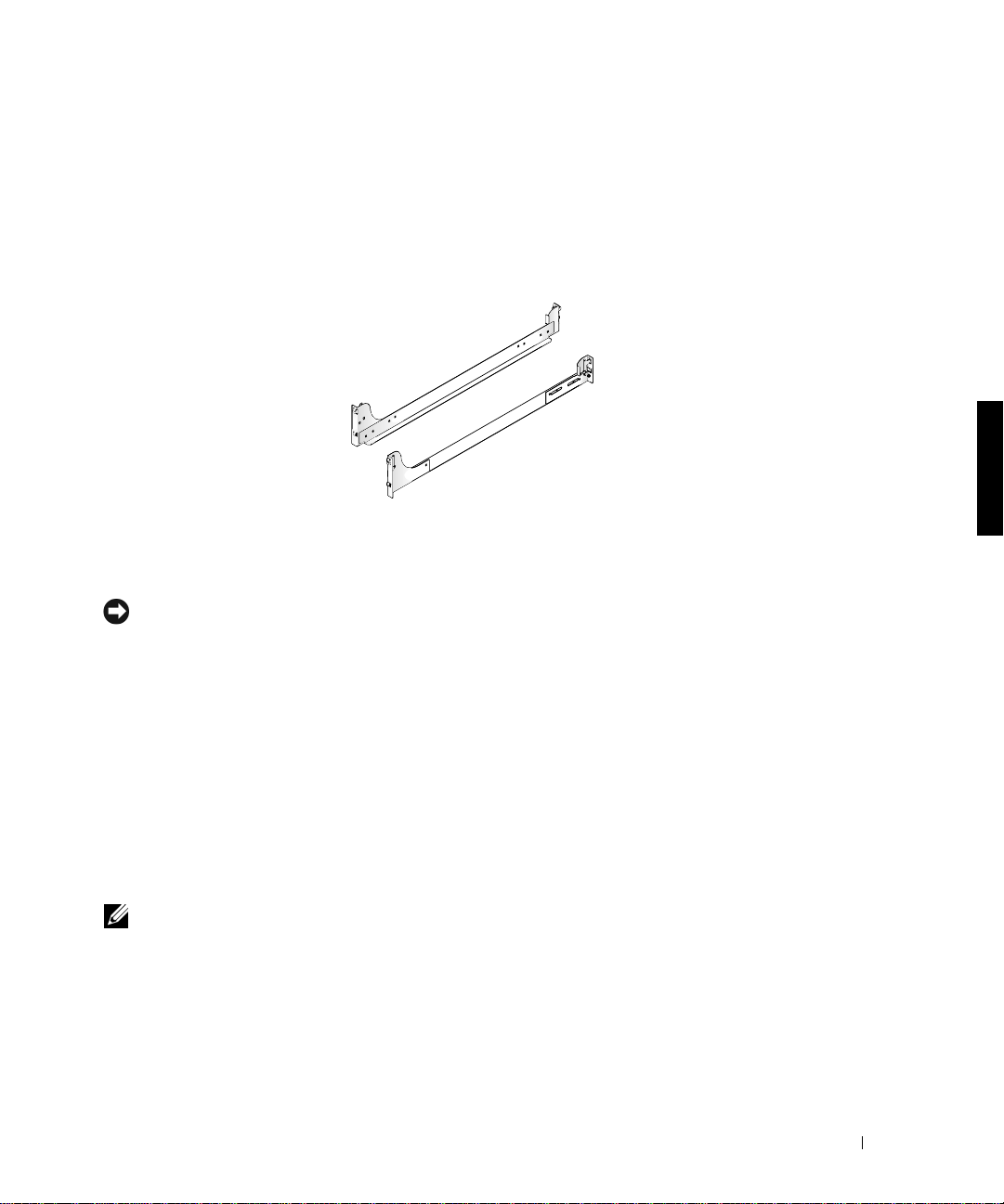
RapidRails Rack Kit Contents
The RapidRails rack kit consists of one pair of RapidRails mounting rails (see Figure 1-1).
1-2 Rack Installation Guide
Page 7

Figure 1-1. RapidRails Rack Kit Contents
RapidRails mounting rails
Dell Rack Requirements
NOTICE: This rack kit is intended to be installed in a Dell rack by trained service technicians.
If you install the kit in any other rack, be sure that the rack meets the specifications o f American
National Standards Institute (ANSI)/Electronic Industries Association (EIA) standard
ANSI/EIA-310-D-92, International Electrotechnical Commission (IEC) 297, and Deutsche
Industrie Norm (DIN) 41494. One rack kit is required for each system that is installed in a rack.
VersaRails Rack Kit Contents
The VersaRails rack kit includes the following items (see Figure 1-2):
• One pair of VersaRails mounting rails
• Eight 10-32 x 0.5-inch Phillips screws
NOTE: The nonmetric screws described in illustrations and in procedural steps are ide ntified by
size and number of threads-per-inch. For example, a #10 Phillips-head screw with 32 threads
per inch is identified as a 10-32 screw.
Figure 1-2. VersaRails Rack Kit Contents
10-32 x 0.5-inch
pan-head Phillips
screws (8)
VersaRails mounting rails
Rac k I n st a ll a t io n G u i de 1-3
Page 8

Non-Dell Rack Requirements
NOTICE: This rack kit is intend ed to be installe d by trained service technicians in a rack that
meets the specifications of American National Standards Institute (ANSI)/Electronic Industries
Association (EIA) standard ANSI/EIA-310-D-92, International Electrotechnical Commission
(IEC) 297, and Deutsche Industrie Norm (DIN) 41494. One rack kit is required for each system
that is installed in a rack.
Before You Begin
Before you install your system in the rack, read the “Safety Instructions” in the front of this
document, as well as the safety instructions in your System Informat ion booklet for
www.dell.com | support.dell.com
additional information.
CAUT ION: When installing multi ple systems in a rack, complete al l of the
procedures for the current system before attempting to install the next system.
Importan t S af ety Inform at ion
Observe the safety precautions in the following subsections when installing your system in
the rack.
CAUT ION: You must strictly follow the procedures in this document to protect
yourself as well as others who may be involved. Your system may be very large
and heavy, and proper preparation and planning are important to prevent injur y
to yourself and others. This becomes increasin gly important when systems are
installed high up in the r ack.
Rack Stabilize r Feet
CAUT ION: Installing systems in a rack without the front and side stabil izer feet
installed and anchored to the floor cou ld cause the rack to tip over, potentially
resulting in bodily injury or death unde r certain circumstances. Therefore,
always install and anchor the stabi lizer feet before installing components in the
rack.
CAUTION: After installing sys tems in a rac k, never pu ll more than one system
out of the rack at one time. The weight of more than o ne extended system could
cause the rack to tip over and cause injury.
The stabilizer feet help prevent the rack from tipping over when a system or other
component is pulled out of the rack. See the documentation provided with the rack cabinet
for instructions on installing and anchoring the stabilizer feet.
1-4 Rack Installation Guide
Page 9

Recommended Tools and Supplies
The following items make the installation easier:
• A #2 Phillips screwdriver (if installing a VersaRails kit)
• Torx T-10 driver (if installing the tower-to-rack kit)
• 3/16-inch hex-head wrench (if installing the tower-to-rack kit)
Installation Tasks
Installing a rack kit involves the following tasks:
1 Removing the rack doors
2 Marking the rack
3 Installing the mounting rails in the rack
4 Installing the tower-to-rack conversion kit (if needed)
5 Installing the system in the rack
6 Replacing the rack doors
NOTE: The procedu r es that follow apply to both Dell rack cabin ets and rack cabinets not
manufactured by Dell unless identified as specific to one or the other.
Removing the Rack Doors
See the procedures for removing doors in the documentation provided with your Dell 24-U
and 42-U rack cabinets. If you have a Dell PowerEdge™ 4210 rack cabinet, see the
procedures in the Dell PowerEdge 4210 Rack Installation Guide. If you have a rack cabinet
not manufactured by Dell, see the manufacturer’s documentation for removing doors.
CAUTION: Because of the s ize and we ight of the rack cabinet doors, neve r
attempt to remove or install them by yourself.
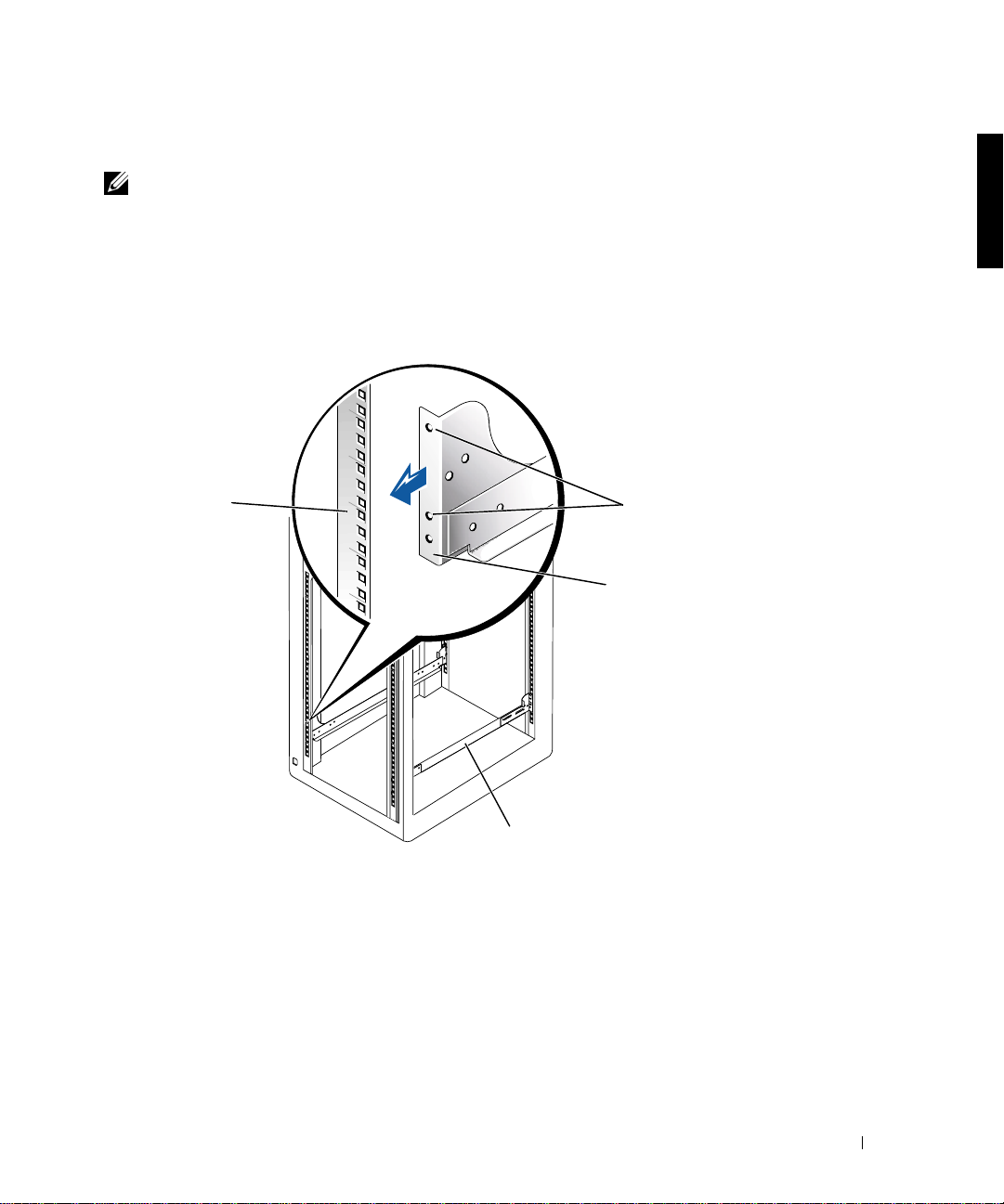
Marking the Rack
NOTE: If you are installing a VersaRails rack kit, skip to the procedure, “Installing the
VersaRails Mounting Rails.”
You must allow 3-U (5.25 inches) of vertical space for each system you install in the rack.
Dell rack cabinets and rack cabinets not manufactured by Dell that meet EIA-310 standar ds
have an alternating pattern of three holes per U with center-to-center hole spacing
(beginning at the top hole of a 1-U space) of 15.9mm, 15.9 mm, and 12.7 mm (0.625-inch,
0.625-inch, and 0.5-inch) for the front and rear vertical rails (see Figure 1-3).
Rac k I n st a ll a t io n G u i de 1-5
Page 10
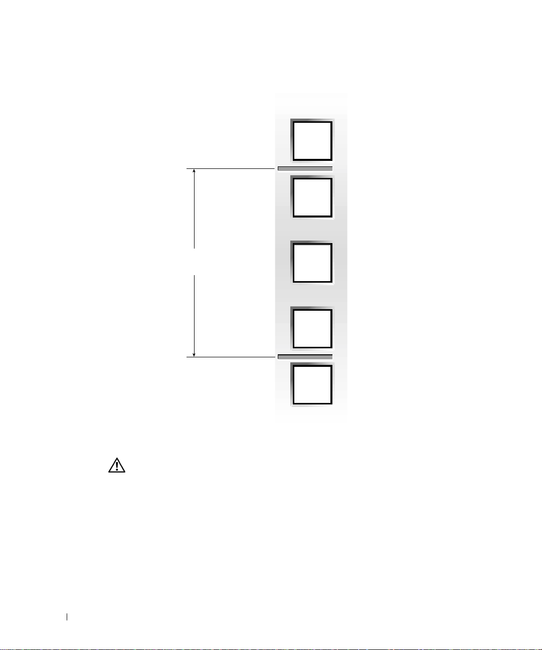
Figure 1-3. One Rack Unit
12.7 mm (0.5 inch)
www.dell.com | support.dell.com
1-U (4.4 centimeters or 1.75) inches)
15.9 mm (0.625 inch)
15.9 mm (0.625 inch)
12.7 mm (0.5 inch)
For more information about requirements for installing components in a Dell rack, see the
Dell Rack Advisor software available on the Dell website at http://support.dell.com.
CAUT ION: If you are installing more than one system, inst all the mounting rails
so that the first system is installed in the lowest available position in the rack.
To mark the rack, perform the following steps:
1 Place a mark on the rack’s fron t vertical rails where you want to locate the bottom of
the system you are installing in the rack cabinet.
The bottom of each 1-U space is at the middle of the narrowest metal space betw een
holes (marked with a horizontal line on some rack cabinets—see Figure 1-3).
1-6 Rack Installation Guide
Page 11
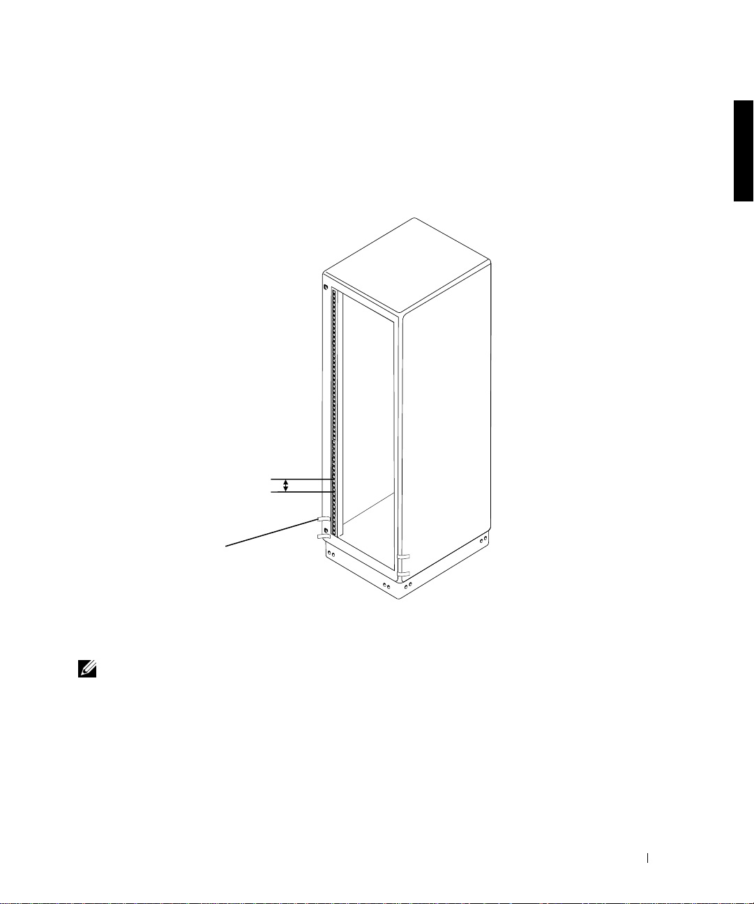
2 Place a mark 13.3 centimeters (5.25 inches) above the original mark (or count up nine
holes in a rack that meets EIA-310 standards) and mark the rack’s front vertical rails
with a felt-tipped marker or place masking tape where the system’s upper edge wi ll be
located (see Figure1-4).
Figure 1-4. Marking the Vertical Rails
3-U (5.25 inches) between
rails (drawing is not to
scale)
tape marking locations for
top and bottom of system
Installing the RapidRails Mounting Rails
NOTE: If you are installing VersaRails rails, see “Installing the VersaRails Mounting Rails.”
1 At the front of the rack cabinet, position one of the mounting rails so that its
mounting-bracket flange fits between the marks or tape you placed on the rack (see
Figure 1-5).
2 Align the rail mounting-bracket flange (on the front of the rail) with the square holes
in the front vertical rails (see Figure 1-5).
Rac k I n st a ll a t io n G u i de 1-7
Page 12
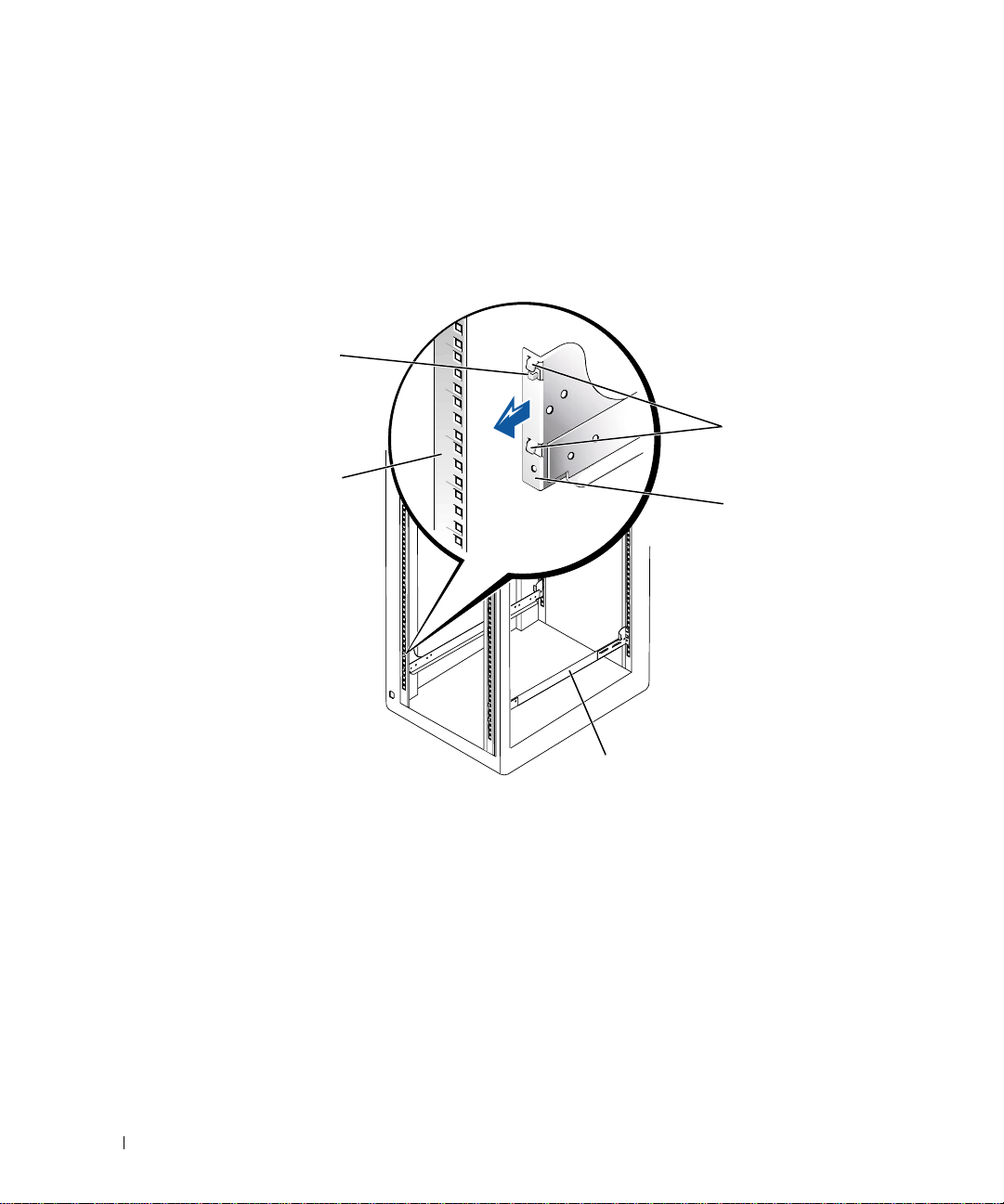
3 Push the rail forward until the mounting hooks are positioned in their square holes on
the vertical rail, and then push down on the mounting-bracket flange until the
mounting hooks seat in the square holes, and the blue push button pops out and
clicks.
Figure 1-5. Installing the RapidRails Mounting Rails
blue push button
www.dell.com | support.dell.com
mounting hooks (2)
front vertical rail
mounting bracket flange
front of rack
RapidRails mounting rail (2)
4 At the back of the cabinet, pull back on the mounting-bra c ket fla n ge until the
mounting hooks are positioned in their square holes on the vertical rail, and then push
down on the mounting-bracket flange until the mounting hooks seat in the square
holes, and the blue push button pops out and clicks.
5 Repeat steps 1 through 4 for the remaining rail on the other side of the rack.
6 Ensure that the rails are mounted at the same position on the vertical rails on each
side of the rack.
1-8 Rack Installation Guide
Page 13
Installing the VersaRails Mounting Rails
NOTE: If you have already installed RapidRails mounting rails, skip this section.
1 At the front of the rack cabinet, position one of the mounting rails so that its
mounting-bracket flange fits at the location you have selected in the rack (see
Figure 1-6).
The vertical rail holes in rack cabinets may be round or square.
Figure 1-6. Installing the VersaRails Mounting Rails
vertical rail
holes may be
round or square
mounting holes (2)
mounting-brac ket flange
front of rack
2 Push the mounting rail forward until the mounting holes are aligned with the holes on
VersaRails mounting rail (2)
the front vertical rail.
3 Using two 10-32 x 0.5 Phillips screws, secure the front mounting-bracket flange to the
front vertical rail.
4 At the back of the cabinet, pull back on the back mounting-bracket flange until it is
aligned with the holes on the back vertical rail.
Rac k I n st a ll a t io n G u i de 1-9
Page 14

5 Using two 10-32 x 0.5 Phillips screws, secure the back mounting-bracket flange to the
back vertical rail.
6 Repeat steps 1 through 5 for the remaining mounting rail on t he other side of t he rack.
7 Ensure that the mounting rails are mounted at the same position on the vertical rails
on each side of the rack.
Installing the Tower-to-Rack Conversion Kit
NOTE: If you have a rack-only version of the system, skip this procedure and proceed to
“Installing the System in the Rack.”
www.dell.com | support.dell.com
CAUT ION: Your system may be very large and heavy. To prevent personal injury,
do not attempt to move the system by yourself.
The tower-to-rack conversion kit includes a rack front panel with rack handles and
thumbscrews.
Removing the Bezel, Drives , Covers, and Front Panel
1 Shut down and turn off power to your system and disconnect your power and
peripheral cables.
2 To remove the bezel (see Figure 1-7):
a Using the system key, unlock the front bezel.
b Swing the bezel away and down from the system until it is perpendicular to the
system.
c Loosen the two thumbscrews that secure the bezel hinge to the front panel (see
Figure 1-7).
d Pull the bezel away and set it aside.
1-10 Rack Installation Guide
Page 15
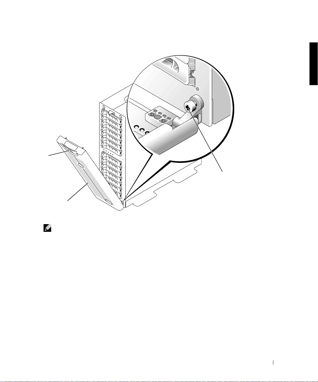
Figure 1-7. Removing the Front Bezel
lock
bezel
thumbscrew
3
Label all hard drives and remove them from the system.
NOTE: Although it is not necessary for the conversion, you might want to remove the two
power-supply and cooling modules at the back of the system chassis to reduce the weight of
the chassis while you are performing this procedure (see your system
T roubleshooting Guide
4
To remove the system left and right covers (see Figure 1-8):
a Remove the two round covers from the top of the tower system.
b Use a 3/16-inch he x-head (Allen) wr ench to remove the he x-sock et cap screws and
for instr uctions for removing and replacing these modules).
Installation and
flat washers from the top of the tower system.
c Slide the left and right cover back, away from the chassis front to disengage, and
pull the covers up, away from the base to remove.
Rac k I n st a ll a t io n G u i de 1-11
Page 16
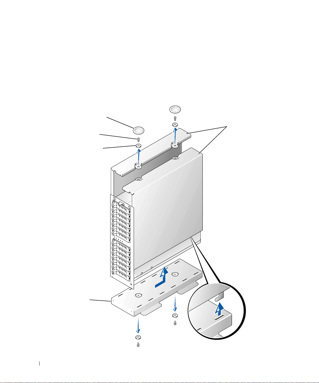
5 To remove the tower system base:
a Lay the system on its right side.
b Use a 3/16-inch hex-head (Allen) wr ench to remove the two hex-socket cap scr ews
and flat washers from the base of the tower chassis
c Remove the base and set it aside (see Figure 1-8).
Figure 1-8. Removing the Tower System Cover
round covers (2)
www.dell.com | support.dell.com
hex-socket
cap screw (4)
flat washer (4)
left and right covers
base
1-12 Rack Installation Guide
Page 17

6 To remove the tower system front panel (see Figure 1-9):
a Posi tion t he system so tha t the front pa nel e xte nds about 2.5 ce ntimeters (1inch)
beyond the edge of the table or work surface.
b Remove the 14 4-40 x 0.25-inch pan head black T-10 Torx screws that secure the
tower front panel to the chas sis.
c Remove the front panel from the system chassis, taking care to avoid damaging
the five plastic light pipes tha t extend through the front panel.
Installing the Rack Front Panel
1 Po sition the r ack fro nt pane l on t he fro nt of th e sys tem chas sis, usin g car e to in stal l the
five light pipes in their holes in the front panel.
NOTE: In the next step, start all 14 T-10 Torx screws in their holes before tightening any
of the screws to ensure proper alignment.
2
Secure the rack front panel to the chassis with the 14 T-10 Torx screws that you
removed in step 6 of the last procedure, “Removing the Bezel, Drives, Covers, an d
Front Panel” (see Figure 1-9).
3 Reinstall the power and cooling modules (if they were removed).
NOTE: Do not install the hard drives until the next procedure, “Installing the System in
the Rack,” is completed.
Rac k I n st a ll a t io n G u i de 1-13
Page 18
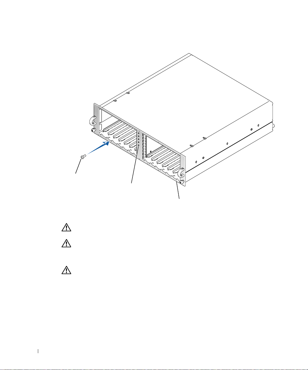
Figure 1-9. Installing the Rack Front Panel
www.dell.com | support.dell.com
screws (14)
light pipes (5)
front panel
Installing the System in the Rack
CAUTION: If you are installing more than one system, install the heaviest system
in the lowest availab le positio n in the rack.
CAUTION:
1
Lift the system into po sition in front of the mounting r ai l s you installed in the rack
cabinet.
CAUTION: Because of the size and weig ht of the sys tem, never attemp t to instal l
the system in the rails by yourself.
Slide the system into the rack until the system front panel is against the vertical rails
2
(see Figure 1-10).
3 Tighten the captive thumbscrews on each side of the system’s front panel.
1-14 Rack Installation Guide
Never
pull more than one component out of the rack at a time.
Page 19
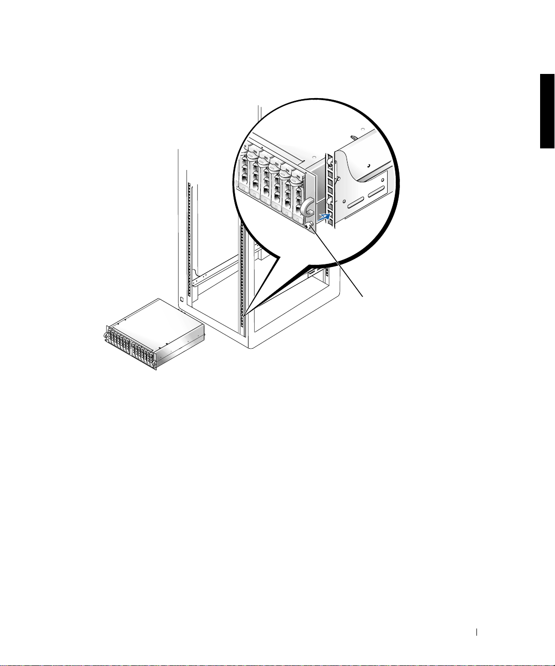
Figure 1-10. Installing the System in the Rack
captive thumbscrews
(2)
Replacing the Rack Doors
See the procedures for replacing doors in the documentation provided with your Dell 24-U
and 42-U rack cabinets. If you have a Dell PowerEdge 4210 rack cabinet, see the procedures
in the Dell PowerEdge 4210 Rack Installation Guide. If you have a rack cabinet not
manufactured by Dell, see the manufacturer’s documentation for replacing doors.
This completes the rack installation of your system.
Rac k I n st a ll a t io n G u i de 1-15
Page 20

1-16 Rack Installation Guide
www.dell.com | support.dell.com
Page 21

Index
C
contents of rack kit, 1-2, 1-3
D
Dell rack requirements, 1-3
Dell Web site, 1-6
doors
removing, 1-5
replacing, 1-15
I
installation
tasks, 1-5
installing
rack front panel, 1-13
RapidRails mounting
rails, 1-7, 1-8
system in rack, 1-14, 1-15
tower-to-rack kit, 1-10
VersaRails mounting rails, 1-9
K
kit contents
illustrated, 1-3
list of, 1-2, 1-3
RapidRails kit, 1-2
VersaRails kit, 1-3
M
marking the rack, 1-5
N
non-Dell rack
requirements, 1-4
R
rack
marking, 1-5
stabilizer feet, 1-4
rack kit contents
illustrated, 1-3
installing, 1-5
list of, 1-2
rack unit, 1-6
RapidRails
kit contents, 1-2
RapidRails mounting rails
installing, 1-8
requirements
Dell rack, 1-3
non-Dell rack, 1-4
S
safety information, 1-4
system
installing in rack, 1-14, 1-15
T
tools
recommended, 1-5
tower-to-rack
installing, 1-10
V
VersaRails
kit contents, 1-3
non-Dell rack
requirements, 1-4
vertical rails
marking, 1-7
one rack unit, 1-6
Index 1
Page 22

2 Index
Page 23

Systèmes Dell™
Guide d'installation du rack
www.dell.com | support.dell.com
Page 24

Remarques, mises en gardes et avertissements
REMARQUE : UNE REMARQUE indique une information importante destinée à vous aider à
mieux utiliser votre ordinateur.
MISE EN GARDE : UNE MISE EN GARDE indique un dommage potentiel pouvant survenir
(ou une perte de données) et vous dit comment éviter le problème.
ATTENTION : Le message ATTENTION indique une situation potentiellement
dangereuse qui, si elle n'est pas évitée, peut prov oquer une blessure mineure ou
modérée.
AVERTISSEMENT : Le message AVERTISSEMENT indique une situation
potentiellement da ngereus e qui, s i elle n'est pas évitée, peut p rovoquer une
blessure mineure ou modérée.
Les informations fourni es dans ce guide sont susceptibles d'être modifiées sans préavi s.
© 2001 Dell Computer Corporation. Tous droits réservés
La reproduction de ce document de quelque manière que ce soit sans l'autorisation écrite de Dell Computer Corporation
est strictement inte rdite.
Marques déposées utilisées dans ce guide :
de Dell Computer Corporation.
Toutes les autres marques déposées et noms de marques utili sés dans ce doc um e nt se rapp orte nt aux soci été s
propriétaires des marques et des noms de ces produits. Dell Computer Corporation décline tout intérêt dans l'utilisation
des marques déposées et des noms de marques ne lui appartenant pas.
Septembre 2001 Réf. 7F206 Rév. A00
Dell
, le logo
DELL, PowerEdge, RapidRails
et
VersaRails
sont des marques
Page 25

Sommaire
Instructions de sécurité . . . . . . . . . . . . . . . . . . . . . . . . . . . . . . 2-1
Instructions d’installation . . . . . . . . . . . . . . . . . . . . . . . . . . . . 2-2
Contenu du kit du rack RapidRails . . . . . . . . . . . . . . . . . . . . . . 2-3
Caractéristiques techniques du rack Dell . . . . . . . . . . . . . . . . . . 2-3
Contenu du kit du rack VersaRails. . . . . . . . . . . . . . . . . . . . . . . 2-3
Caractéristiques techniques des ra cks
d'autres marques que Dell . . . . . . . . . . . . . . . . . . . . . . . . . . . . . 2-4
Avant de commencer . . . . . . . . . . . . . . . . . . . . . . . . . . . . . . . . 2-4
Informations importantes sur la sécurité . . . . . . . . . . . . . . . . . . 2-4
Pieds stabilisateurs du rack . . . . . . . . . . . . . . . . . . . . . . . . . . . . 2-5
Outils et fournitures recommandés . . . . . . . . . . . . . . . . . . . . . . . 2-5
Tâches d'installation . . . . . . . . . . . . . . . . . . . . . . . . . . . . . . . . . 2-5
Retrait des portes du rack . . . . . . . . . . . . . . . . . . . . . . . . . . . . 2-6
Index
Marquage du rack . . . . . . . . . . . . . . . . . . . . . . . . . . . . . . . . . . 2-6
Installation des rails de montage RapidRails. . . . . . . . . . . . . . . . 2-8
Installation des rails de montage VersaRails . . . . . . . . . . . . . . . 2-10
Installation du kit de conversion de tour en rack . . . . . . . . . . . 2-11
Retrait du cache, des disques, des capots et
du panneau avant . . . . . . . . . . . . . . . . . . . . . . . . . . . . . . . . . . 2-11
Installation du panneau avant du rack . . . . . . . . . . . . . . . . . . . 2-14
Installation du système dans le rack . . . . . . . . . . . . . . . . . . . . 2-15
Remise en place des portes du rack . . . . . . . . . . . . . . . . . . . . 2-16
Sommaire 3
Page 26

Figures
Figure 2-1. Contenu du kit du rack RapidRails . . . . . . . . . . . 2-3
Figure 2-2. Contenu du kit du rack VersaRails . . . . . . . . . . . . 2-4
Figure 2-3. Unité à un rack. . . . . . . . . . . . . . . . . . . . . . . . . . 2-7
Figure 2-4. Marquage des rails verticaux. . . . . . . . . . . . . . . . 2-8
Figure 2-5. Installation des rails de montage RapidRails . . . . 2-9
Figure 2-6. Installation des rails de montage VersaRails. . . . 2-10
Figure 2-7. Retrait du cache avant. . . . . . . . . . . . . . . . . . . . 2-12
Figure 2-8. Retrait du capot du système en tour . . . . . . . . . . 2-13
Figure 2-9. Installation du panneau avant du rack . . . . . . . . 2-15
Figure 2-10. Installation du système dans le rack. . . . . . . . . . 2-16
4 Sommaire
Page 27

Instructions de sécurité
Respectez les consignes de sécurité de ce guide pour assurer votre sécurité personnelle et
pour contribuer à protéger votre serveur, votre système de stockage ou appareil, des
dommages potentiels. Pour obtenir toutes les informations de sécurité réglementaires et les
garanties, reportez-vous au document intitulé Informations système concernant votre
système Dell™.
Précautions à suivre concernant les produits destinés à être montés dans des
racks
Pour la stabilité du rack et pour votre sécurité, veuillez respecter les précautions suivantes.
Reportez-vous également à la documentation accompagnant le système et le rack pour
connaître les avertissements et/ou les mises en garde et les procédures spécifiques.
Les serveurs, les systèmes de stockage et les appareils sont considérés comme les
composants d'un rack. Ainsi, le terme "composant" fait référence à tout serveur, tout
système de stockage ou appareil, aussi bien qu'aux différents périphériques ou matériels.
ATTENTION : L'installation de composants d'un système dans un rack sans placer
de stabilisateurs avant et latéraux peut provoquer le basculeme nt du rack, et
comporte ans certaines situations un risque de blessures pouvant être mortelles.
C'est pourquoi il faut tou jours installer les stabil isateurs avant d 'installer le s
composants du rack.
ATTENTION : Après avoir insta llé le système/les composants dan s un rack, ne
tirez jamais plus d'un comp osant du rack sur le s supports cou lissants. Le poid s
représenté par plus d'un composant étendu pourrait en effet provoqu er le
basculement du rack et blesser l'utilisateur.
REMARQUE : Votre système Dell est certifié sur le plan de la sécurité en tant qu'unité
autonome et en tant que composan t destiné à ê tre utilisé da ns u ne armoire rack Dell , à l'aid e du
kit de rack client de Dell. L'installation du système et du kit de rack Dell dans un rack d'une
autre marq u e n' a r e ç u au cu n e ho mologation de s o rg a nis m e s de c e rt if ic ation de la s éc u ri t é. I l e s t
de votre entière responsabilité de faire évaluer par un organisme de sécurité agréé la
combinaison finale du système et du kit de rack Dell dans un rack d'une autre marque. Dell
décline toute responsabilité et toutes garanties liées à ce type de combinaisons.
• Les kits de racks sont destinés à être installés dans un rack Dell par des techniciens
expérimentés. Si vous installez ce kit dans tout autre rack, assurez-vous que ce rack
répond à toutes les spécifications d'un rack Dell.
• Ne déplacez pas seul les racks volumineux. En raison de la hauteur et du poids du rack,
il est recommandé de confier l'exécution de cette tâche à deux personnes au
minimum.
Guide d'installation du rack 2-1
Page 28

• Avant de travailler sur le rack, as sur ez-vous que les stabi lisateurs s ont bien en place sur
le rack et au sol, et que tout le poids du rack r epose sur le so l. Installez les sta bilisateu rs
avant et latéraux (pour un rack simple) ou les stabilisateurs avant (pour les racks
multiples) avant de travailler sur le rack.
• Chargez toujours le rack du bas vers le haut, en plaçant toujours la plus forte charge en
premier.
• Assurez-vous que le rack est bien de nive au avant de so rtir l'un des compo sants à l'ai de
des supports coulissants.
• Agissez avec précaution lorsque vous appuyez sur les verrous des rails pour les libérer
et faire glisser un composant hors ou dans le rack. Les rails coulissants pourraient en
effet vous coincer les doigts.
www.dell.com | support.dell.com
• Après avoir inséré un composant dans le rack, étendez le rail en position maximum
jusqu'à son verrouillage puis faites glisser le composant dans le rack.
• Ne surchargez pas le circuit d'alimentation c.a. dérivé alimentant le rack en électricité.
La charge totale du rack ne doit pas excéder 80 % de la puissance du circuit dérivé.
• Assurez-vous que l'air circule suffisamment entre les composants du rack.
• Ne montez jamais sur l'un des composants du système lors de l'entretien.
Instructions d’installation
Ce guide d'installation contient des instructions s'adressant à des techniciens de
maintenance qualifiés et explique comment installer un ou plusieurs systèmes dans une
armoire rack. Le kit de rack RapidRails™ peut être installé dans toutes les armoires rack
Dell™ ; le kit de rack VersaRails™ peut être installé dans la plupart des armoires rack
conformes aux normes de l'industrie. Les procédures d'installation des kits de rack
RapidRails et VersaRails sont les mêmes. Un kit de rack est nécessair e pour chaque sy stè me
devant être installé dans l'armoire rack.
ATTENTION : N'essayez pas d'installer de composants de kit de rack prévus pour
un autre système. Utilisez u niquement le kit de rack de vo tre système. S i vous
employez le kit d'un autre système, vous risquez d'end ommager le système et
d'exposer autrui et vous- même à des risques de bl essures.
REMARQUE : Si votre système est une configuration en tour, vous devez d'abord le convertir
en rack, à l'aide d'un kit de conversion de tour en rack. Les instructions d'installation de ce type
de kit sont fournies dans le présent document.
2-2 Guide d'installation du rack
Page 29
Contenu du kit du rack RapidRails
Le kit de rack RapidRails se compose d'une paire de rails de montage RapidRails (voir la
Figure 2-1).
Figure 2-1. Contenu du kit du rack RapidRails
Rails de montage RapidRails
Caractéristiques techniques du rack Dell
MISE EN GARDE : Ce kit de rack est destiné à être installé dans un rack Dell par des
techniciens expérimentés. Si vous installez ce kit dans un autre type de rack, assurez-vous que ce
rack répond aux spécifications des organismes suivants : American National Standards Institute
(ANSI)/Electronic Industries Association (EIA) standard ANSI/EIA-310-D - 92, International
Electrotechnical Commission (IEC) 297, et Deutsche Industrie Norm (DIN) 41494. Un kit est
nécessaire pour chaque système installé dans un rack.
Contenu du kit du rack VersaRails
Le kit du rack VersaRails comprend les éléments suivants (voir Figure 2-2) :
• Une paire de rails de montage VersaRails
• Huit vis à tête Phillips 10-32 x 0,5 pouce
REMARQUE : Les vis non métriques décrites dans les illustrations et dans les étapes des
procédures sont identifiées par la taille et le nombre des filetages par pouce. Par exemple, une
vis à tête Phillips n° 10 avec 32 filetages est désignée par l'appellation vis 10-32.
Guide d'installation du rack 2-3
Page 30
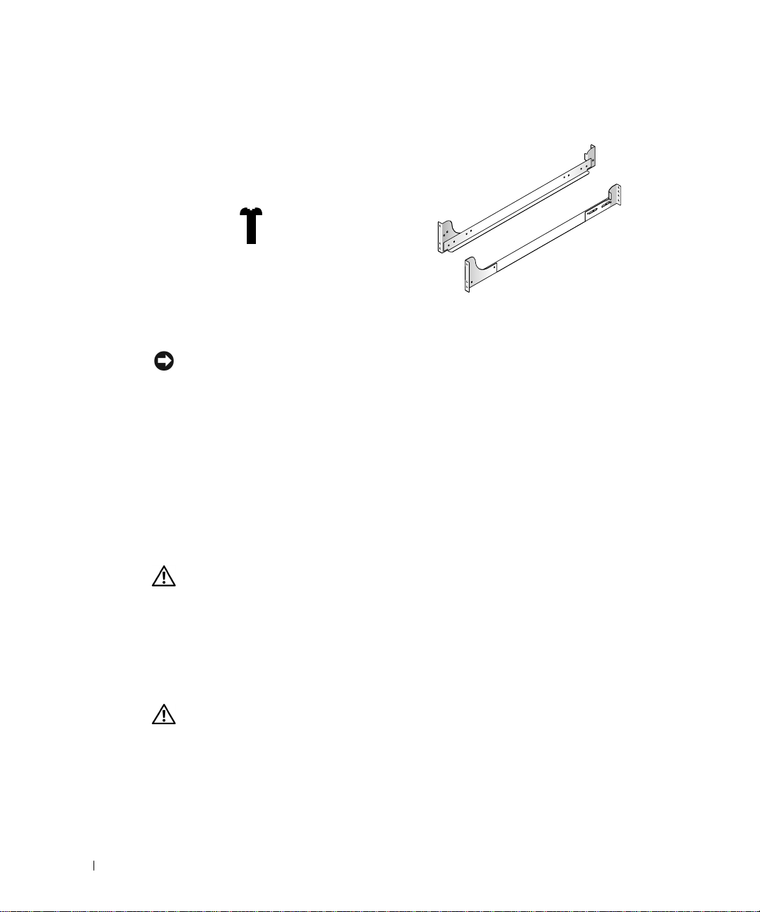
Figure 2-2. Contenu du kit du rack VersaRails
vis à tête plate
Phillips 10-32 x
0,5 pouce (8)
www.dell.com | support.dell.com
Rails de montage VersaRails
Caractéristiques techniques des racks d'aut res marques que Dell
MISE EN GARDE : Ce kit de rack est prévu pour être installé par des techniciens de
maintenance qualifiés dans un rack conforme aux spéci fications des organismes suivants :
American National Standards Institute (ANSI)/Electronic Industries Association (EIA)
standard ANSI/EIA-310-D-92, International Electrotechnical Commission (IEC) 297, et
Deutsche Industrie Norm (DIN) 41494. Un kit de rack est nécessaire pour chaque système
installé dans un rack.
Avant de commencer
Avant d'installer votre système dans le rack, lisez les “Instructions de sécurité” au début de
ce document, ainsi que les instructions de sécurité de votre manuel Informations système
qui vous fourniront des renseignements supplémentaires.
ATTENTION : Lorsque vous installez plusieurs systèmes dans un rack, exécutez
toutes les procédures s'appliquant au système en cours avant d'essayer d'i nstaller
le système suiva nt.
Informati o n s importantes s ur la sé c u rité
Observez les précautions de sécurité décrites dans les sous-sectio ns suivantes lors de
l'installation de votre système dans le rack.
ATTENTION : Vous devez respecter à la lettre les procédures de ce document afin
de garantir votre propr e protection ainsi qu e celle d'autru i. Votre système peut
être extrêmement lourd et volumineux. Un e préparation et une planificati on
adéquates sont don c importantes a fin d'éviter to ut risque de ble ssure pour vousmême ou autrui. Ces précautions sont d'autant plus importantes lorsque les
systèmes sont install és très haut da ns le rack.
2-4 Guide d'installation du rack
Page 31

Pieds stabilisateurs du rack
ATTENTION : Si vous ins tallez des systè mes dans un rack sans placer de pieds
stabilisateurs avant et l atéraux fixés a u sol, le rack peut basculer e t entraîne
dans certaines situations un risque de blessures pouvant être mortelles. C'est
pourquoi il faut toujours inst aller et fixer les pieds stabilisateu rs avant
d'installer les composants dans le rack.
ATTENTION : Après avoir insta llé des systèmes dans un rack, ne retirez jamais
plus d'un sy stème à l a fois h ors du r ack. Le poids rep résenté par plus d'un
système lorsqu'il est extrait pourrait en effet provoquer le basculement du rack
et blesser l'utilisateur.
Les pieds stabilisateurs empêchent le rack de basculer lorsque vous en extrayez un système
ou un autre composant. Consultez la documentation fournie avec l'armoire rack pour savoir
comment installer et fixer les pieds stabilisateurs.
Outils et fournitures recommandés
Procurez-vous les outils et éléments suivants qui vous faciliteront l'installation :
• Un tournevis Phillips n° 2 (pour installer un kit VersaRails)
• Un tournevis Torx T-10 (pour installer le kit de conversion de tour en rack)
• Clé mâle normale 3/16 pouces (pour installer le kit de conversion de tour en rack)
Tâches d'installation
L'installation d'un kit de rack comprend les opérations suivantes :
1 Retrait des portes du rack
2 Marquage du rack
3 Installation des rails de montage dans le rack
4 Installation du kit de conversion de tour en rack (si nécessaire)
5 Installation du système dans le rack
6 Remise en place des portes du rack
REMARQUE : Les procédures suivantes s'appliquent à la fois aux armoires en rack Dell et à
celles d'autres fabricants que Dell sauf indication contraire.
Guide d'installation du rack 2-5
Page 32

Retrait des portes du rack
Pour savoir comment retirer les portes du rack, reportez-vous à la documentation fournie
avec les armoires en rack Dell 24U et 42U. Si vous possédez un rack Dell PowerEdge™
4210, reportez-vous aux procédures contenues dans le Guide d'installation du rack Dell
PowerEdge 4210. Si vous possédez un rack d'un autre fabricant que Dell, reportez-vous à la
documentation du fabricant pour savoir comment retirer les portes.
ATTENTION : Compte tenu du poids et de la taille des portes de l'armoire rack,
ne déposez ou n'insta llez jama is les portes seul.
www.dell.com | support.dell.com
Marquage du rack
REMARQUE : Si vous installez un kit de rack VersaRails, passez directement à la procédure
intitulée “Installation des rails de montage VersaRails.”
Vous devez laisser un espace vertical de 3 U (5,25 pouces) pour chaque système installé
dans le rack. Les armoires rack Dell et celles d'autres fabricants conformes aux normes EIA310 alternent un groupe de trois trous par U (unité). Les espacement entre chacun des trois
trous, mesurés du centre d'un trou jusqu'au centre du trou suivant (en commençant par le
trou supérieur d'un espace de 1U) sont respectivement de 15,9mm, 15,9 mm et 12,7 mm
(0,625 pouces, 0,625 pouces et 0,5 pouces) pour les rails verticaux avant et arrière (voir la
Figure 2-3).
2-6 Guide d'installation du rack
Page 33

Figure 2-3. Unité à un rack
1U (4,4 cm ou 1,75 pouces)
12,7 mm (0,5 pouces)
15,9 mm (0,625 pouces)
15,9 mm (0,625 pouces)
12,7 mm (0,5 pouces)
Pour obtenir plus d'informations sur les règles à respecter pour installer des composants
dans un rack, reportez-vous au logiciel Dell Rack Advisor disponible sur le sit e Web de Dell
à l'adresse suivante : http://support.dell.com.
ATTENTION : Si vous installez plusieurs systèmes, installez les rails de montage
de façon à ce que le premier système soit placé le plus bas possi ble dans le rack.
Pour marquer le rack, procédez comme suit :
1 Placez une marque sur les rails verticaux avant du rack, à l'endroit correspondant au
bas du système à installer dans l'armoire rack.
Le bas de chaque espace 1U se trouve au milieu de l'espacement métallique le plus
étroit entre les trous (repéré par une ligne horizontale sur certaines armoires rack —
voir la Figure 2-3).
Guide d'installation du rack 2-7
Page 34

2 Placez une marque à 13,3 cm (5,25 pouces) au-dessus de la marque originale (ou
comptez neuf trous vers le haut dans les racks conformes aux normes EIA-310), puis
marquez les rails verticaux du rack avec un stylo feutre ou collez de la bande
protectrice adhésive à l'endroit correspondant au rebord supérieur du système (voir la
Figure 2-4).
Figure 2-4. Marquage des rails verticaux
www.dell.com | support.dell.com
3U (5,25 pouces) entre les
rails (le dessin n'est pas à
l'échelle)
emplacemen t s où coller la ba nde
de protection correspondant
au haut et au bas du système
Installation des rails de montage RapidRails
REMARQUE : Si vous installez les rails VersaRails, reportez-vous à la section “Installation
des rails de montage VersaRails”.
1
A l'avant de l'armoire rack, positionnez l'un des rails de montage de façon à ce que la
bride de fixation soit située entre les marques (ou la bande adhésive) placées sur le
rack (voir la Figure 2-5).
2-8 Guide d'installation du rack
Page 35

2 Alignez la bride de fixation du rail (à l'avant du rail) sur les trous carrés des rails
verticaux avant (voir la Figure 2-5).
3 Pousse z le rail vers l'avant jusqu'à ce que les crochets de fixation soient positionnés
dans leur trous carrés sur le rail vertical, puis exercez une pression vers le bas sur la
bride de fixation jusqu'à ce que les crochets de fixation s'enclenchent dans les trous
carrés et que le bouton-poussoir bleu ressorte et émette un déclic.
Figure 2-5. Installation des rails de montage RapidRails
bouton-poussoir bleu
crochets de montage (2)
rail vertical avant
bride de fixation
avant du rack
4 A l'arrière de l'armoire, tirez la bride de fixation vers l'arrière jusqu'à ce que les crochets
rails de montage RapidRails (2)
de fixation soient positionnés dans leur trous carrés sur le rail vertical, puis ex ercez une
pression vers le bas sur la bride de fixation jusqu'à ce que les crochets de fixation
s'enclenchent dans les trous carrés et que le bouton-poussoir bleu ressorte et émette
un déclic.
5 Répétez les opérations des étapes 1 à 4 pour le rail restant de l'autre côté du rack.
6 Vérifiez que les rails sont montés à la même position sur les rails verticaux de chaque
côté du rack.
Guide d'installation du rack 2-9
Page 36

Installation des rails de montage VersaRails
REMARQUE : Si vous avez déjà installé les rails de montage RapidRails, sautez cette section.
1 A l'avant de l'armoire rack, positionnez l'un des rails de montage de façon à ce que la
bride de fixation soit située à l'emplacement choisi dans le rack (voir la Figure 2-6).
Les trous du rail vertical du rack peuvent être percés de trous ronds ou carrés.
Figure 2-6. Installation des rails de montage VersaRails
www.dell.com | support.dell.com
les trous du rail
vertical peuvent être
ronds ou carrés
trous de montage (2)
bride de fixation
avant du rac k
2 Poussez le rail de montage vers l'avant jusqu'à ce que les trous de montage soient
alignés sur les trous du rail vertical avant.
3 A l'aide de deux vis Phillips 10-32 x 0,5, vissez la bride de fixation avant sur le rail
vertical.
4 A l'arrière de l'armoire, tirez sur la bride de fixation jusqu'à ce qu'elle soit alignée sur les
trous du rail vertical arrière.
2-10 Guide d'installation du rack
rails de montage VersaRails (2)
Page 37

5 A l'aide de deux vis Phillips 10-32 x 0,5, vissez la bride de fixation arrière sur le rail
vertical arrière.
6 Répétez les opérations des étapes 1 à 5 pour le rail de montage restant de l'autre côté
du rack.
7 Vérifiez que les rails de montage sont montés à la même position sur les rails verticaux
de chaque côté du rack.
Installation du kit de conversion de tour en rack
REMARQUE : Si vous avez seulement une version en rack du système, sautez cette procédure
et passez directement à la section “Instal lation du système dans le rack”.
ATTENTION : Votre système peut être extrêmement lourd et volumineux. Pour
éviter toute blessure, ne tentez pas de le déplacer seul.
Le kit de conversion de tour en rack comporte un panneau de rack avant avec des poignées
de rack et des vis à molette.
Retrait du cache, des disques, des capots et du panneau avant
1 Arrêtez le système et mettez-le hors tension, puis débranchez le cordon d'alimentation
et les câbles de périphériques.
2 Pour retirer le cache (voir la Figure 2-7) :
a Déverrouillez le cache avant à l’aide de la clé du système.
b Dégagez le cache en l'écartant et en l'abaissant jusqu'à ce qu'il soit perpendiculaire
au système.
c Desserrez les deux vis à molette fixant la charnière du cache au panneau avant
(voir la Figure 2-7).
d Retirez le cache et mettez-le de côté.
Guide d'installation du rack 2-11
Page 38

Figure 2-7. Retrait du cache avant
www.dell.com | support.dell.com
verrou
vis molette
cache
3
Etiquetez tous les disques durs et retirez-les du système.
REMARQUE : Bien qu e cela ne soit pas indi spensable pour effect uer la conversion, vous
pouvez retirer les deux modules d'alimentation et de ventilation à l'arrière du châssis du
système afin de réduire le po ids du châssis pendant l'exécution de la procédure (p our savoir
comment retirer et remplacer ces modules, consultez les instructions du
et de dépannage
4 Pour retirer les capots gauche et droit du système (voir la Figure 2-8) :
a Retirez les deux capuchons ronds sur le haut du système en tour.
b A l'aide d'une clé mâle 3/16 (Allen), retir e z les vis à tête cylindrique à 6 pans et les
rondelles plates du haut du système en tour.
c Faites coulisser le capot gauche et droit vers l'arrière, en les écartant de l'avant du
châssis pour les dégager, puis tirez-les vers le haut, en les écartant de la base, pour
les retirer.
2-12 Guide d'installation du rack
Guide d'installation
du système).
Page 39

5 Pour retirer la base du système en tour :
a Couchez le système sur son côté droit.
b A l'aide d'une clé mâle 3/16 (Allen), retirez les deux vis à tête cylindrique à 6 pans
et les rondelles plates de la base du système en tour.
c Retirez la base et mettez-la de côté (voir la Figure 2-8).
Figure 2-8. Retrait du capot du système en tour
capuchons ronds (2)
vis à tête cylindrique
6 pans (4)
rondelles plates (4)
capots gauche et droit
base
Guide d'installation du rack 2-13
Page 40

6 Pour retirer le panneau avant du système en tour (voir la Figure 2-9):
a Positionnez le système de façon à ce que le panneau avant dépasse d'environ 2,5
centimètres (1 pouce) du rebord de la table ou de la surface de travail.
b Retirez les vis noires T-10 Torx 14 4-40 x 0,25 pouces à tête plate qui fixent le
panneau avant de la tour sur le châssis.
c Retirez le panneau avant du châssis du système, en veillant à éviter d'endommager
les cinq témoins lumineux en plastique qui passent par le panneau avant.
Installation du panneau avant du rack
1 Positionnez le panneau avant du rack sur l'avant du châssis du système, en veillant à
www.dell.com | support.dell.com
engager les cinq témoins lumineux dans leurs orifices correspondant dans le panneau
avant.
REMARQUE : Ensuite, introduisez les 14 vis T-10 Torx dans leurs trous avant de les
visser, afin d'être certain qu'elles sont correctement alignées.
2
Vissez le panneau avant du rack sur le châssis à l'aide des 14 vis T-10 Torx que vous
avez retirées à l'étape 6 de la dernière procédure, “Retrait du cache, des disques, des
capots et du panneau avant” (voir la Figure 2-9).
3 Réinstallez les modules d'alimentation et de ventilation si vous les aviez retirés.
REMARQUE : N'installez pas les disques durs avant d'avoir term iné la procédure
suivante, “Installation du système dans le rack”.
2-14 Guide d'installation du rack
Page 41

Figure 2-9. Installation du panneau avant du rack
vis (14)
tuyaux (5)
panneau
Installation du système dans le rack
ATTENTION : Si vous installez plusieurs systèmes, installez le système le plus
lourd à l'emplacement le plus bas pos sible dans le rack.
ATTENTION :
1
Soulevez le système et positionnez-le en face des rails de montage que vous av ez
Ne retirez jamais
installés dans l'armoire rack.
ATTENT ION : En rais on de la taille et du poids du sys tème, ne tentez jamais de
l'installer seul dans les rails.
Faites coulisser le système dans le rack jusqu'à ce que le panneau avant du système soit
2
placé contre les rails verticaux (voir la Figure 2-10).
3 Resserrez les vis à molette captives de chaque côté du panneau avant du système.
plus d'un composant du rack en même temps.
Guide d'installation du rack 2-15
Page 42
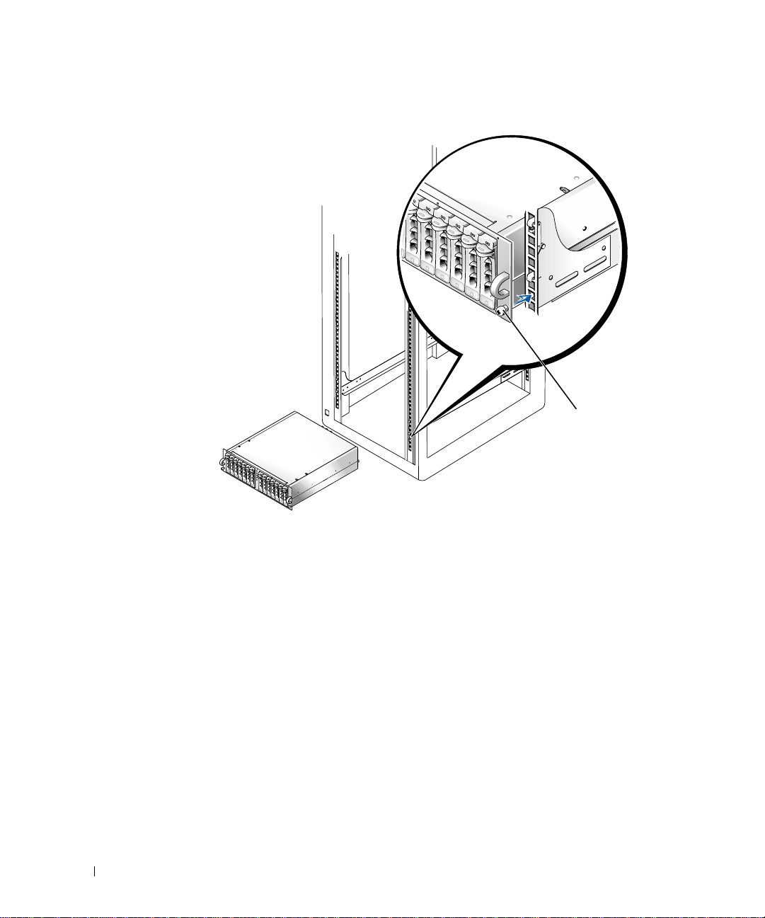
Figure 2-10. Installation du système dans le rack
www.dell.com | support.dell.com
vis à molette captives
(2)
Remise en place des portes du rack
Pour savoir comment remettre en place les portes du rack, reportez-vous à la documentation
fournie avec les armoires en rack Dell 24U et 42U. Si vous possédez un rack Dell PowerEdge
4210, reportez-vous aux procédures du Guide d'installation du rack Dell PowerEdge 4210. Si
vous possédez un rack d'un autre fabricant que Dell, reportez-vous à la documentation du
fabricant pour savoir comment remettre en place les portes.
L'installation de votre système dans le rack est terminée.
2-16 Guide d'installation du rack
Page 43

Index
C
caractéristiques techniques
rack Dell, 2-3
racks d'autres marques que
Dell, 2-4
Caractéristiques techni ques
du rack Dell, 2-3
contenu du kit
illustration, 2- 3 , 2 - 4
Kit RapidRails, 2-3
Kit VersaRails, 2-3
liste, 2-3
contenu du kit de rack, 2-3
illustration, 2- 3 , 2 - 4
installation, 2-5
liste, 2-3
I
Informations sur la
sécurité, 2-4
installation
kit de conversion de tour en
rack, 2-11
opérations, 2-5
panneau avant du rack, 2-1 4
Rails de montage
RapidRails, 2 - 8 , 2 - 9
Rails de montage
VersaRails, 2-10
système dans le rack, 2-15,
2-16
K
kit de conversion de tour en
rack
installation, 2-11
M
marquage du rack, 2 -6
O
Outils
recommandés, 2-5
P
portes
réinstallation, 2-16
retrait, 2-6
R
rack
marquage, 2-6
pieds stabilisateurs, 2-5
racks d'autres marques que
Dell
caractéristiques
techniques, 2-4
Rails de montage RapidR ails
installation, 2-9
rails verticaux
marquage, 2-8
unité à un rack, 2-7
RapidRails
contenu du kit, 2-3
S
Site Web Dell, 2-7
système
installation dans le rack, 2-15,
2-16
U
unité de rack, 2-7
V
VersaRails
caractéristiques techniques des
racks d'autres marques que
Dell, 2-4
contenu du kit, 2-3
Index 1
Page 44

2 Index
Page 45

Dell™-Systeme
Rack-Installationsanleitung
www.dell.com | support.dell.com
Page 46

Anmerkungen, Hinweise, Vorsichtshinweise und
Warnungen
HINWEIS: Ein HINWEIS enthält wichtige Informationen, mit deren Hilfe Sie Ihren Computer
besser nutzen können.
BITTE BEACHTEN: BITTE BEACHTEN weist auf eine mögliche Beschädigung von Hardware
oder den Verlust von Daten hin und beschreibt, wie di eses Problem vermieden werden kann.
VORSICHT: Die Angabe VORSICHT warnt vor einer möglicherweise gefährlichen
Situation, die bei Ni chtbeachten zu l eichten oder mittelschweren Schä den führen
kann.
WARNUNG: Eine WARNUNG warnt vor einer möglicherweise gefährlichen
Situation, die bei Ni chtbeachten zu s chweren Verletzungen führen kan n.
Die in diesem Dokument enthaltenen Informationen können ohne Vorankündigung geändert werden.
© 2001 Dell Computer Corporation. Alle Rechte vorbehalten.
Eine Reproduktion dieses Dokuments in jeglicher Form ist nur mit vorheriger schrif tl iche r Gene hm i gung der Dell
Computer Corporation er la ubt .
Die in diesem Text verwendeten Warenzeichen:
Warenzeichen der Dell Computer Corporation.
Andere in diesem Dokument möglicherw ei se ve rwendete Warenzeichen und Handelsbezei chnungen sind unter
Umständen Marken und Namen der entsprechenden Firmen oder ihrer Produkte. Die Dell Computer Corporation erhebt
keinen Anspruch auf Warenzeichen oder Handelsnamen mit Ausnahme ihrer eigenen.
September 2001 P/N 7F206 Rev. A00
Dell
, das
DELL
-Logo,
PowerEdge, RapidRails
und
VersaRails
sind
Page 47

Inhalt
Sicherheitshinweise . . . . . . . . . . . . . . . . . . . . . . . . . . . . . . . . . 3-1
Installationsanleitung . . . . . . . . . . . . . . . . . . . . . . . . . . . . . . . 3-2
Inhalt des RapidRails-Rack-Kits . . . . . . . . . . . . . . . . . . . . . . . . 3-3
Dell-Rack-Anforderungen . . . . . . . . . . . . . . . . . . . . . . . . . . . . . 3-3
Inhalt des VersaRails-Rack-Kits . . . . . . . . . . . . . . . . . . . . . . . . 3-3
Rack-Anforderungen anderer Anbieter . . . . . . . . . . . . . . . . . . . . 3-4
Bevor Sie beginnen . . . . . . . . . . . . . . . . . . . . . . . . . . . . . . . . . 3-4
Wichtige Sicherheitsinformationen . . . . . . . . . . . . . . . . . . . . . . 3-4
Rack-Stabilisatoren. . . . . . . . . . . . . . . . . . . . . . . . . . . . . . . . . . 3-5
Empfohlene Werkzeuge und Zubehör . . . . . . . . . . . . . . . . . . . . . 3-5
Installationsarbeiten . . . . . . . . . . . . . . . . . . . . . . . . . . . . . . . . . 3-5
Abnehmen der Rack-Türen . . . . . . . . . . . . . . . . . . . . . . . . . . . . 3-6
Index
Markieren des Racks . . . . . . . . . . . . . . . . . . . . . . . . . . . . . . . . 3-6
Installieren der RapidRails-Montageschienen . . . . . . . . . . . . . . . 3-9
Installieren der VersaRails-Montageschienen . . . . . . . . . . . . . . 3-10
Installieren des Tower-nach-Rack-Konvertier-Kits . . . . . . . . . . 3-11
Entfernen der Blende, Laufwerke,
Abdeckung und Frontplatte . . . . . . . . . . . . . . . . . . . . . . . . . . . 3-11
Installieren der Frontplatte des Racks . . . . . . . . . . . . . . . . . . . 3-14
Installieren des Systems im Rack . . . . . . . . . . . . . . . . . . . . . . 3-15
Einsetzen der Rack-Türen . . . . . . . . . . . . . . . . . . . . . . . . . . . 3-16
Inhalt 3
Page 48

Abbildungen
Abbildung 3-1. Inhalt des RapidRails-Rack-Kits . . . . . . . . . . . . . 3-3
Abbildung 3-2. Inhalt des VersaRails-Rack-Kits . . . . . . . . . . . . . 3-4
Abbildung 3-3. Eine Rack-Einheit. . . . . . . . . . . . . . . . . . . . . . . . 3-7
Abbildung 3-4. Markieren der vertikalen Schienen. . . . . . . . . . . . 3-8
Abbildung 3-5. Installieren der RapidRails-Montageschienen. . . . 3-9
Abbildung 3-6. Installieren der VersaRails-Montageschienen . . . 3-10
Abbildung 3-7. Entfernen der Frontblende. . . . . . . . . . . . . . . . . 3-12
Abbildung 3-8. Entfernen der Tower-Systemabdeckung . . . . . . . 3-13
Abbildung 3-9. Installieren der Rack-Frontplatte. . . . . . . . . . . . 3-15
Abbildung 3-10. Installieren des Systems im Rack. . . . . . . . . . . . 3-16
4 Inhalt
Page 49

Sicherheitshinweise
Beachten Sie die nachfolgenden Sicherheitshinweise, um Ihre eigene Sicherheit zu
gewährleisten und Schäden an Ihrem Server, Ihrem Speichersystem oder an Ihren Geräten
zu vermeiden. Vollständige Informationen über die Sicherheitsanforderungen, Vorschriften
und Garantiebedingungen finden Sie in dem zu Ihrem Dell™-System gehörenden
Dokument System informationen.
Vorsichtsmaßnahmen für rack-montierbare Produkte
Um die Stabilität und Sicherheit des Racks zu gewährleisten, befolgen Sie bitte die
folgenden Vorsichtsmaßnahmen. Spezielle Warnungen und/oder Sicherheitshinweise und
Prozeduren finden Sie auch in der zum System gehörenden Dokumentation zur RackInstallation.
Server, Speichersysteme und Geräte werden als Komponenten in einem Rack betrachtet.
Der Begriff „Komponente“ bezieht sich also auf einen beliebigen Server, ein Speichersystem
oder ein Gerät, sowie auf verschiedene Peripheriegeräte oder Zusatzhardware.
VORSICHT: Werden Systemkomponenten in einem Rack installiert, an dem die
vorderen und seitli chen Stab ilisatoren fe hlen, ka nn das Rack um kippen, was
unter bestimmten Bedi ngungen zu Verletzungen oder so gar tödlichen
Verletzungen führen kann. Installieren Sie daher immer erst die Stabilis atoren,
bevor Sie Komponenten in dem Rack installieren.
VOR SICHT: Ziehen Sie nach der Installation von Systemen/Komponenten in
einem Rack niemals mehr als eine Komponente gleichzeitig auf ihren
Gleitschienen aus dem Rack. Durch das Gewicht von mehr als einer Komponente
kann das Rack umkippen und Verletzungen hervorrufen.
HINWEIS: Ihr Dell-System ist als frei stehende Einheit und für die Verwendung als
Komponente in Dell-Gestellschränken sicherheitszertifiziert, wobei das Dell Customer Rack-Kit
eingesetzt werden muss. Die Installation Ih res Systems und Rack-Kits in Gestellschränken
anderer Hersteller wurde von keiner Prüfbehörde untersucht. Es liegt in Ihrer Verantwortung,
die Eignung der endgültigen Kombination von Dell-Systemen und Rack-Kits für den Einsatz in
Gestellschränken anderer Hersteller durch eine zert ifizierte Prüfbehörde untersuchen zu lassen.
Dell lehnt jede Haftung und Gewährleistung für solche Kombinationen ab.
• System-Rack-Kits müssen von geschulten Servicetechnikern in einem Dell-Rack
installiert werden. Wenn Sie das Kit in einem anderen Rack installieren, vergewissern
Sie sich, dass das Rack die Spezifikationen eines Dell-Racks erfüllt.
• Bewegen Sie große Racks nicht ohne fremde Hilfe. Wegen der Höhe und des
Gewichtes des Racks sollte diese Aufgabe von mindestens zwei Personen gemeinsam
durchgeführt werden.
Rack-Installationsanleitung 3-1
Page 50

• Bevor Sie an einem Rack arbeiten, vergewissern Sie sich, dass die Stab ilisatoren sicher
an dem Rack befestigt sind und bis auf den Boden reichen und dass das gesamte
Gewicht des Racks auf dem Boden lastet. Installieren Sie an einem einzelnen Rack
vordere und seitliche Stabilisatoren bzw. an mehreren miteinander verbundenen Racks
vordere Stabilisatoren, bevor Sie an dem Rack arbeiten.
• Belasten Sie das Rack immer von unten nach oben und bauen Sie die schwerste
Komponente zuerst in dem Rack ein.
• V er gewissern Sie sich, dass das Rack eben und stabil steht, bevor Sie eine Komponente
aus dem Rack ziehen.
• Seien Sie vorsichtig, wenn Sie auf die Verriegelung der Komponentenschiene drücken
www.dell.com | support.dell.com
und eine Komponente in das Rack schieben bzw. aus dem Rack ziehen, da Sie sich in
den Gleitschienen die Finger klemmen können.
• Nachdem eine Komponente in das Rack eingesetzt wurde, ziehen Sie die Schienen
vorsichtig bis in die Verriegelungsposition und schieben Sie dann die Komponente in
das Rack.
• Überlasten Sie nicht den Wechselstromkreis, über den das Rack mit Strom versorgt
wird. Die Gesamtlast des Racks sollte 80 Prozent der Nennbelastbarkeit des
Stromkreises nicht überschreiten.
• Stellen Sie sicher, dass eine ausreichende Luftzufuhr zu den Komponenten in dem
Rack gewährleistet ist.
• Treten Sie nicht auf ein System oder eine Komponente und stellen Sie sich nicht
darauf, wenn Sie an anderen Systemen oder Komponenten in einem Rack Arbeiten
durchführen.
Installationsanleitung
Diese Installationsanleitung enthält Anweisungen zur Installation eines oder mehrerer
Systeme in einem Gestellschrank durch geschulte Servicetechniker. Das RapidRails™ RackKit kann in allen Dell™-Gestellschränken installiert werden und das VersaRails™ Rack-Kit
in den meisten Standardgestellschränken. Die Installation der beiden Rack-Kits erfolgt in
ähnlicher Weise. Für jedes im Gestellschrank zu installierende System wird ein Rack-Kit
benötigt.
VORSICHT: Versuchen Sie nicht, Rack-Kit-Komponenten einzub auen, die für ein
anderes System vorgesehen sind. Verwenden Si e ausschließlic h das für Ihr
System konzipi erte Rack-K it. Wenn Sie das Rack-K it für ein and eres Sys tem
verwenden, k ann das System beschäd igt wer den und Sie selb st oder andere
Personen könnten sich verletzen.
3-2 Rack-Installationsanleitung
Page 51

HINWEIS: Handelt es sich bei Ihrem System um eine Tower-Version, müssen Sie das System
zuerst mithilfe eines Tower-nach-Rack-Konvertier-Kits in eine Rack-Version konvertieren.
Anleitungen zur Installation dieses Kits finden Sie in diesem Dokument.
Inhalt des RapidR ails-Rack-Kits
Das RapidRails-Rack-Kit enthält ein Paar RapidRails-Montageschienen (siehe Abbildung 3-1).
Abbildung 3-1. Inhalt des RapidRails-Rack-Kits
RapidRails-Montageschienen
Dell-Rack-Anforderungen
BITTE BEACHTEN: Di eses Rack-Kit muss von gesch ul ten Servicetechnikern in einem Dell-
Rack installiert werden. Wenn Sie das Kit in einem anderen Rack installieren, vergewissern Sie
sich, dass das Rack die Spezifikationen des American National Standards Institute
(ANSI)/Electronic Industries Association (EIA) Standard ANSI/EIA-310-D-92, der
International Electrotechnical Commission (IEC) 297 und die Deutsche Industrie Norm (DIN)
41494 einhält. Für je de s Sy st e m, das in einem Rack inst alliert wird, wird ein R ack - K it be nö ti g t.
Inhalt des VersaRails-Rack-Kits
Das VersaRails-Rack-Kit enthält die folgenden Teile (siehe Abbildung 3-2):
• Ein Paar VersaRails-Montageschienen
• Acht 10-32 x 0,5 Zoll Kreuzschlitzschrauben
HINWEIS: Die in den Abbildungen und Prozeduren ge n an nt e n nicht m etr i sc h en Sch ra ub e n
werden anhand ihrer Größe und der Anzahl der Windungen pro Zoll bezeichnet. Beispielsweise
wird eine Kreuzschlitzschraube Nr. 10 mit 32 Windungen pro Zoll als 10-32-Schraube
bezeichnet.
Rack-Installationsanleitung 3-3
Page 52

Abbildung 3-2. Inhalt des VersaRails-Rack-Kits
10-32 x 0,5-Zoll
FlachkopfKreuzschlitzschrauben (8)
www.dell.com | support.dell.com
VersaRails-Montageschienen
Rack-Anforderungen ande rer Anbieter
BITTE BEACHTEN: Dieses Rack-Kit muss von geschulten Servicetechnikern in einem Rack
installiert werden, das die Spezifikationen des American National Standards Institute
(ANSI)/Electronic Industries Association (EIA) Standard ANSI/EIA-310-D-92, der
International Electrotechnical Commission (IEC) 297 und die Deutsche Industrie Norm (DIN)
41494 einhält. Für je des Sy ste m , da s in einem R a c k in stalliert wird, wi rd ein Rack-Kit benötigt.
Bevor Sie beginnen
Vor der Installation Ihres Systems in dem Rack müssen Sie die „Sicherheitshinweise“ am
Anfang dieses Dokumentes sowie die Sicherheitshinweise in der Broschüre System
information lesen.
VORSICHT: Wenn Sie mehrere Systeme in einem Rack in stallieren, be enden Sie
alle Prozeduren für das ger ad e inst all ie rte Syste m, bev or Sie da s nächst e Sy stem
installieren.
Wichtige Sicherheitsinformationen
Beachten Sie die Sicherheitsmaßnahmen in den folgenden Unterabschnitten, wenn Sie Ihr
System in dem Rack installieren.
VORSICHT: Die in diesem Dokument angegeb enen Prozed uren mü ssen exakt
befolgt werden, damit Sie selbst und andere Beteiligte nicht gefährdet werden.
Ihr System kann sehr groß und schwer sein; Sie sollten die Installation gründlich
vorbereiten und planen, um jegliche Verletzungen zu vermeiden. Dies gilt
besonders, wenn Systeme oben im Rack i nstalliert werde n.
3-4 Rack-Installationsanleitung
Page 53

Rack-Stabilisatoren
VORSICHT: Werden Systeme in einem Rack installiert, dessen vo rdere und
seitliche Stabilisatoren nicht montiert und am Boden befestigt wurden, kann das
Rack umkippen. Dies kann unter b estimmt en Bed ingun gen zu Verletzungen oder
sogar tödlichen Verletzunge n führen. Install ieren und befes tigen Sie daher
immer erst die Stabili satoren, bevor S ie Komponenten in dem Rack in stallieren.
VORSICHT: Nach der Installation von Systemen in einem Rack sol lten Sie
niemals mehr als ein System glei chzeitig aus dem Rack ziehen. Durch das
Gewicht von mehr als einem herausgezogenen System kann das Rack umkippen
und Verletzungen verursachen.
Die Stabilisatoren verhindern, dass das Rack umkippt, wenn ein System oder eine andere
Komponente aus dem Rack herausgezogen wird. Anleitungen zur Installation und
Befestigung der Stabilisatoren finden Sie in der mit dem Gestellschrank gelieferten
Dokumentation.
Empfohlene Werkzeuge und Zubehör
Die folgenden Hilfsmittel erleichtern die Installation:
• Kreuzschlitz-Schrauberdreher Nr. 2 (bei der Installation eines VersaRails-Kits)
• Torx T-10-Schraubendreher (bei der Installation des Tower-nach-Rack-Kits)
• 3/16-Zoll Sechskantschlüssel(bei der Installation des Tower-nach-Rack-Kits)
Installationsarbeiten
Bei der Installation eines Rack-Kits müssen die folgenden Aufgaben ausgeführt werden:
1 Abnehmen der Rack-Türen
2 Markieren des Racks
3 Installieren der Montageschienen in das Rack
4 Installieren des Tower-nach-Rack-Konvertier-Kits (falls erforderlich)
5 Installieren des Systems im Rack
6 Einsetzen der Rack-Türen
HINWEIS: Die im Folgenden besch riebenen Verfahren gelten für Dell-Gestellschränke und f ür
Gestellschränke anderer Anbieter gleichermaßen, sofern nicht anders angegeben.
Rack-Installationsanleitung 3-5
Page 54

Abnehmen der Rack-Türen
Weitere Informationen zum Abnehmen der Tür en fi nden Sie der den D ell 2 4-U- und 42 -UGestellschränken beiliegenden Dokumentation. Wenn Sie einen Gestellschrank des Typs
Dell PowerEdge™ 4210 haben, lesen Sie die Prozeduren in Installationshinweise für das
PowerEdge 4210 Rack. Wenn Ihr Gestellschrank kein Dell-Produkt ist, lesen Sie die
Anleitungen des Herstellers zum Abnehmen der Türen.
VORSICHT: Wegen der Größe und des Gewichts der Gestellschranktüren sollten
Sie keinesfalls versuche n, sie o hne fremde Hilfe abzunehmen oder einzuba uen.
www.dell.com | support.dell.com
Markieren des Racks
HINWEIS: Wenn Sie ein VersaRails-Rack-Kit installieren, lesen Sie bei der Prozedur
„Installieren der VersaRails-Montageschi enen“ weiter.
Sie müssen zwischen den einzelnen Systemen, die Sie in dem Rack installieren, einen
vertikalen Abstand von 3-U (5,25 Zoll) einhalten. Dell-Gestellschränke und
Gestellschränke anderer Anbieter, die den EIA-310-Standards entsprechen, haben ein sich
wiederholendes Muster aus drei Löchern pro U-Einheit, deren Mittenabstand zueinander
(beginnend in der Mitte des oberen Lochs einer 1-U-Einheit) 15,9 mm, 15,9 mm und
12,7 mm (0,625 Zoll, 0,625 Zoll und 0,5 Zoll) für die vorderen und hinteren vertikalen
Schienen beträgt (siehe Abbildung 3-3).
3-6 Rack-Installationsanleitung
Page 55

Abbildung 3-3. Eine Rack-Einheit
1-U (4,4 cm oder 1,75 Zoll)
12,7 mm (0,5 Zoll)
15,9 mm (0,625 Zoll)
15,9 mm (0,625 Zoll)
12,7 mm (0,5 Zoll)
Weitere Informationen über die Anforderungen zur Installation von Komponenten in
einem Dell-Rack finden Sie in der Software Dell Rack Advisor auf der Dell-Website unter
http://support.dell.com.
VORSICHT: Wenn Sie mehr als ein System install ieren, ins tallieren S ie die
Montageschienen so, dass das erste System möglichst weit unte n im Rack
eingebaut wird.
Rack-Installationsanleitung 3-7
Page 56

Um das Rack markieren, gehen Sie wie folgt vor:
1 Bringen Sie auf den vorderen vertikalen Schienen des Racks eine Markierung an der
Stelle an, an der sich die Unterseite des Systems befinden soll, das Sie in den
Gestellschrank einbauen.
Die Unterkante jeder 1-U-Einheit befindet sich in der Mitte des schmalsten
Metallzwischenraums zwischen den Löchern (auf einigen Gestellschränken mit einer
horizontalen Linie gekennzeichnet – siehe Abbildung 3-3).
2 Bringen Sie 13,3 cm (5,25 Zoll) über der Originalmarkierung eine Markierung an
(oder zählen Sie in einem Rack, das den EIA-310-Standards entspricht, von unten
nach oben neun Löcher ab); markieren Sie dann die Stelle, an der sich die obere Kante
www.dell.com | support.dell.com
des Systems befinden wird, mit einem Filzstift bzw. mit einem Stück Kreppband
(siehe Abbildung 3-4).
Abbildung 3-4. Markieren der vertikalen Schienen
3-U (5,25 Zoll) zwischen
Schienen (Zeichnung ist
nicht maßstabgetreu)
Kreppband zur
Markierung der oberen
und unteren System kanten
3-8 Rack-Installationsanleitung
Page 57

Installieren der RapidRails-Montageschienen
HINWEIS: Wenn Sie VersaRails-Schienen installieren, lesen Sie „Installieren der VersaRails-
Montageschienen“.
Positi onier e n Sie an der Vorderseite des Gestellschrankes eine der Montageschienen
1
so, dass der zugehörige Montagehalterungsflansch zwischen die Markierungen oder
das Kreppband an dem Rack passt (siehe Abbildung 3-5).
2 Richten Sie den Montagehalterungsflansch der Schienen (auf der Vorderseite der
Schiene) mit den rechteckigen Löchern in den vorderen vertikalen Schienen aus (siehe
Abbildung 3-5).
3 Drücken Sie die Schiene nach vorn, bis die Montagehaken in ihren rechteckigen
Löchern auf der vertikalen Schiene positioniert sind. Drücken Sie dann den
Montagehalterungsflansch nach unten, bis die Montagehaken in die rechteckigen
Löcher eingerastet sind, der blaue Druckknopf herausspringt und ein Klicken zu hören
ist.
Abbildung 3-5. Installieren der RapidRails-Montageschienen
blauer Druckknopf
vordere vertikale
Schiene
Rack-Vorderseite
Montagehaken (2 )
Flansch der
Montagehalterung
RapidRails-Montageschienen (2)
Rack-Installationsanleitung 3-9
Page 58

4 Ziehen Sie an der Rückseite des Gestellschrankes den Flansch der Montagehalterung
nach hinten, bis die Montagehaken in ihren rechteckigen Löchern auf der vertikalen
Schiene positioniert sind. Drücken Sie dann den Montagehalterungsflansch nach
unten, bis die Montagehaken in die rechteckigen Löcher eingerastet sind, der blaue
Druckknopf herausspringt und ein Klicken zu hören ist.
5 Wiederholen Sie die Schritte 1 bis 4 für die andere Schiene auf der anderen Seite des
Racks.
6 Achten Sie darauf, dass die Schienen auf jeder Rack-Seite jeweils an der gleichen
Stelle auf den vertikalen Schienen montiert werden.
www.dell.com | support.dell.com
Installieren der VersaRails-Montageschienen
HINWEIS: Wenn Sie bereits RapidRails-Montageschienen installiert haben, können Sie diesen
Abschnitt überspringen.
Positi onier e n Sie an der Vorderseite des Gestellschrankes eine der Montageschienen
1
so, dass der zugehörige Montagehalterungsflansch an die Stelle passt, die Sie in dem
Rack ausgewählt haben (siehe Abbildung 3-6).
Die vertikalen Schienen in Gestellschränken haben runde bzw. quadratische Löcher.
Abbildung 3-6. Installieren der VersaRails-Montageschienen
vertikale
Schienen können
runde oder
rechteckige
Löcher haben
Montagelöcher (2)
Flansch der
Montagehalterung
Rack-Vorderseite
3-10 Rack-Installationsanleitung
VersaRails-Montageschienen (2)
Page 59

2 Drücken Sie die Montageschiene nach vorn, bis die Montagelöcher mit den Löchern
auf der vorderen vertikalen Schiene ausgerichtet sind.
3 Befestigen Sie den vorderen Montagehalterungsflansch mit zwei 10-32 x 0,5-Zoll-
Kreuzschlitzschrauben an der vorderen vertikalen Schiene.
4 Ziehen Sie auf der Rückseite des Gestellschrankes den hinteren Montagehalterungs-
flansch nach hinten, bis er mit den rechteckigen Löchern auf der hinteren vertikalen
Schiene ausgerichtet ist.
5 Befestigen Sie den hinteren Montagehalterungsflansch mit zwei 10-32 x 0,5-Zoll-
Kreuzschlitzschrauben an der hinteren vertikalen Schiene.
6 Wiederholen Sie die Schritte 1 bis 5 für die andere Montageschiene auf der anderen
Seite des Racks.
7 Achten Sie darauf, dass die Montageschienen auf jeder Rack-Seite jeweils an der
gleichen Stelle auf den vertikalen Schienen montiert werden.
Installieren des Tower-nach-Rack-KonvertierKits
HINWEIS: Wenn Ihre Systemversion nur für Racks vorgesehen ist, können Sie diese Prozedur
überspringen und bei „Installieren des Systems im Rack“ weiterlesen.
VO RSICHT: Ihr System kann sehr groß und schwer se in. Um Verletzungen zu
vermeiden, sollten Sie keinesfalls vers uchen, das System ohne frem de Hilfe zu
bewegen.
Das Tower-nach- Rack-K o nvertier-Kit enthält eine Rack-Frontplatte mit Rack-Handgriffen
und Flügelschrauben.
Entfernen der Blende, Laufwerke, Abdeckung und Frontplatte
1 Fahren Sie das System herunter, schalten Sie die Stromversorgung des Systems aus
und ziehen Sie die Strom- und peripheren Kabel ab.
2 Um die Blende zu entfernen, führen Sie folgende Schritte aus (siehe Abbildung 3-7):
a Öffnen Sie die Frontblende mit dem Systemschlüssel.
b Schwenken Sie die Blende nach außen und unten, bis sie senkrecht zu dem
System steht.
c Lösen Sie die beiden Flügelschrauben, mit denen das Blendenscharnier an der
Frontplatte befestigt ist (siehe Abbildung 3-7).
d Ziehen Sie die Blende heraus und legen Sie sie beiseite.
Rack-Installationsanleitung 3-11
Page 60

Abbildung 3-7. Entfernen der Frontblende
www.dell.com | support.dell.com
Riegel
Flügelschraube
Blende
3
Beschriften Sie alle Festplatten und nehmen Sie sie aus dem System heraus.
HINWEIS: Obwohl es für die Konvertierung nicht zwingend notwendig ist, sollten Sie die
beiden Netzteil - und Kühlmodule an der Rückseite des System-Chassis entfernen, und das
Gewicht des Chassis währ end der Durchführung dieses Verfahrens möglichst gering zu
halten (Informationen zum Aus- und Einbauen dieser Module finden Sie in der dem System
beiliegenden
4 Um die linken und rechten Systemabdeckungen abzunehmen, führen Sie die
Anleitung zur Installation und Fehlersuche
folgenden Schritte aus (siehe Abbildung 3-8):
a Entfernen Sie die beiden runden Abdeckungen auf der Oberseite des Tower-
Systems.
b Entfernen Sie die Sechskantschrauben und flachen Unterlegscheiben auf der
Oberseite des Tower-Systems mithilfe eines 3/16-Zoll-Inbusschlüssels.
c Schieben Sie die linke und rechte Abdeckung nach hinten und weg von der
Chassis-Vorderseite; ziehen Sie dann die Abdecku n gen na ch oben und weg von
dem Sockel.
3-12 Rack-Installationsanleitung
).
Page 61

5 Um den Sockel des Tower-Systems zu entfernen, führen Sie die folgenden Schritte aus:
a Legen Sie das System auf die rechte Seite.
b Entfernen Sie die beiden Sechskantschrauben und flachen Unterlegscheiben auf
der Unterseite des Tower-Systems mithilfe eines 3/16-Zoll-Inbusschlüssels.
c Entfernen Sie den Sockel und legen Sie ihn beiseite (siehe Abbildung 3-8).
Abbildung 3-8. Entfernen der Tower-Systemabdeckung
runde Abd eckungen (2)
Sechskantsch
raube (4)
flache Unterlegscheibe (4)
linke und rechte
Abdeckungen
Sockel
Rack-Installationsanleitung 3-13
Page 62

6 Um die Frontplatte des Tower-Systems zu entfernen, führen Sie die folgenden
Schritte aus (siehe Abbildung 3-9):
a Positionieren Sie das System so, dass die Frontplatte ca. 2,5 cm (1Zoll) über die
Tischkante oder Arbeitsfläche hinausragt.
b Entfernen Sie die 14 schwarzen 4-40 x 0,25-Zoll T-10 Torx-Flachkopf-Schrauben,
mit denen die Frontplatte des Towers an dem Chassis befestigt ist.
c Entfernen Sie die Frontplatte von dem System-Chassis und achten Sie dabei
darauf, dass Sie nicht die fünf Kunststofflichtröhren beschädigen, die durch die
Frontplatte hindurchreichen.
www.dell.com | support.dell.com
1 Positionieren Sie die Rack-Frontplatte an der Vorderseite des System-Chassis und
installieren Sie die fünf Lichtröhren in ihren Löchern auf der Frontplatte.
HINWEIS: Im nächsten Schritt positionieren Sie zuerst alle vierzehn T-10 To rx-
Schrauben in ihren Löchern, bevor Sie die Schrauben anziehen, um eine einwandfreie
Ausrichtung zu gewährleisten.
2 Befestigen Sie die Rack-Frontplatte mit den vierzehn T- 10 Torx-Schrauben, die Sie in
Schritt 6 der vorigen Prozedur „Entfernen der Blende, Laufwerke, Abdeckung und
Frontplatte“ entfernt haben, an dem Chassis (siehe Abbildung 3-9).
3 Bauen Sie die Strom- und Kühlmodule wieder ein (sofern sie entfernt wurden).
HINWEIS: Setzen Sie die Festplatten erst ein, wenn das nächste Verfahren „Installieren
des Systems im Rack“ abgeschlossen ist.
Installieren der Frontplatte des Racks
3-14 Rack-Installationsanleitung
Page 63

Abbildung 3-9. Installieren der Rack-Frontplatte
Schrauben (14)
Lichtröhren (5)
Frontplatte
Installieren des Systems im Rack
VORSICHT: Wenn Sie mehrere Systems installieren, in stallieren S ie das
schwerste Sys tem mögl ichst w eit unt en in d em Rack.
VORSICHT: Ziehen Sie
Rack heraus.
Heben Sie das System vor die Montageschienen, die Sie in den Gestellschrank
1
niemals
eingebaut haben, in Position.
VORSICHT: Wegen der Größe und d es Gewic hts de s System s so llten Si e niemal s
versuchen, das System ohne fremde Hilfe in den Schi enen zu installieren.
2
Schieben Sie das System in das Rack, bis die System-Frontplatte auf den vertikalen
Schienen aufliegt (siehe Abbildung 3-10).
3 Ziehen Sie die selbstsichernden Flügelschrauben auf beiden Seiten der System-
Frontplatte a n.
mehr als eine Komponente g leichzeitig aus dem
Rack-Installationsanleitung 3-15
Page 64

Abbildung 3-10. Installieren des Systems im Rack
www.dell.com | support.dell.com
Selbstsichernde
Flügelschraube (2)
Einsetzen der Rack-Türen
Weitere Informationen über das Einsetzen der Türen finden Sie in der den Dell 24-U- und
42-U-Gestellschränken beiliegenden Dokumentation. Wenn Sie ein Rack des Typs Dell
PowerEdge 4210 haben, lesen Sie die P rozedur en in Installa tionshi nweise für das PowerEdge
4210 Rack. Wenn Ihr Gestellschrank kein Dell-Produkt ist, lesen Sie die Dokumentation
des Herstellers zum Einsetzen der Türen.
Damit ist die Rack-Installation Ihres Systems abgeschlossen.
3-16 Rack-Installationsanleitung
Page 65

Index
A
Anforderungen
Dell-Rack, 3-3
Racks anderer Anbieter, 3-4
D
Dell-Rack-Anforderungen,
3-3
Dell-Website, 3-7
E
Einbau
Rack-Frontplatte, 3-14
RapidRails-Montageschienen,
3-9
System im Rack, 3-15, 3-16
Tower-nach-Rack-Kit, 3-11
VersaRails-Montageschienen,
3-10
I
Inhalt des Rack-Kits, 3-3
Installation
Schritte, 3-5
K
Kit-Inhalt
abgebildet, 3-3 , 3- 4
Liste, 3-3
RapidRails-Kit, 3-3
VersaRails-Kit, 3-3
M
Markieren des Racks, 3-6
R
Rack
Markieren, 3-6
Stabilisatoren, 3-5
Rack-Einheit, 3-7
Rack-Kit-Inhalt
abgebildet, 3-3 , 3- 4
Einbau, 3-5
Liste, 3-3
Racks anderer Anbieter
Anforderungen, 3-4
RapidRails
Kit-Inhalt, 3-3
RapidRails-Montag eschienen
Einbau, 3-9
S
Sicherheitsinformationen, 3-4
System
Installation im Rack, 3-15,
3-16
T
Tower-nach-Rack
Einbau, 3-11
Türen
abnehmen, 3-6
einsetzen, 3-16
V
VersaRails
Kit-Inhalt, 3-3
Rack-Anforderungen anderer
Anbieter, 3-4
Vertikale Schienen
eine Rack-Einheit, 3- 7
Markieren, 3-8
W
Werkzeuge
empfohlen, 3-5
Index 1
Page 66

2 Index
Page 67

Sistemas Dell™
Guía de montaje del rack
www.dell.com | support.dell.com
Page 68

Notas, avisos, precauciones y advertencias
NOTA: una NOTA indica información importante que le ayudará a usar mejor su ordenador.
AVISO: un AVISO indica un posible daño en el hardware o la pérdida de datos, e informa de
cómo evitar el problema.
PRECAUCIÓN: un m ensaje de PRECAUCIÓ N señala una situaci ón potenci almente
peligrosa que, de no evitarse, pued e provocar lesiones l eves o moderad as.
ADVERTENCIA: una ADVERTENCIA indica una situ ació n poten cialm ente pel igros a
que, si no se evita, puede producir les iones graves.
La información de este documento está sujeta a modificaciones sin previo aviso.
© 2001 Dell Computer Corporation. Reservados tod os los de rechos.
Queda prohibida su reprodu cció n en cu al qui er m edio sin la autorización por escrito de Del l Com puter Corporation.
Marcas comerciales que aparecen en el texto:
marcas comerciales de Dell Computer Corpor ation.
En este documento pueden utilizarse otras marcas y nombres comerciales para referirse a las entidades propietarias
de dichas marcas y nombres o a sus productos. Dell Computer Corporation renuncia a cualquier derecho sobre las
marcas y nombres comerciales que no sean de su propiedad.
Septiembre de 2001 P/N 7F206 Rev. A00
Dell
, el logotipo de
DELL, PowerEdge, RapidRails
y
VersaRails
son
Page 69

Contenido
Instrucciones de seguridad . . . . . . . . . . . . . . . . . . . . . . . . . . . . 4-1
Instrucciones de instalación . . . . . . . . . . . . . . . . . . . . . . . . . . . 4-2
Contenido del kit de rack RapidRails . . . . . . . . . . . . . . . . . . . . . 4-3
Requisitos para racks Dell . . . . . . . . . . . . . . . . . . . . . . . . . . . . . 4-3
Contenido del kit de rack VersaRails . . . . . . . . . . . . . . . . . . . . . 4-3
Requisitos para racks que no sean Dell . . . . . . . . . . . . . . . . . . . . 4-4
Antes de empezar . . . . . . . . . . . . . . . . . . . . . . . . . . . . . . . . . . 4-4
Información de seguridad importante. . . . . . . . . . . . . . . . . . . . . 4-4
Pie estabilizador para el rack . . . . . . . . . . . . . . . . . . . . . . . . . . 4-5
Herramientas y suministros recomendados . . . . . . . . . . . . . . . . . 4-5
Tareas de montaje . . . . . . . . . . . . . . . . . . . . . . . . . . . . . . . . . . . 4-5
Desmontaje de las puertas del rack . . . . . . . . . . . . . . . . . . . . . . 4-6
Índice
Marcado del rack . . . . . . . . . . . . . . . . . . . . . . . . . . . . . . . . . . 4-6
Instalación de las guías de montaje RapidRails . . . . . . . . . . . . . . 4-9
Instalación de las guías de montaje VersaRails . . . . . . . . . . . . . 4-10
Montaje del kit de conversión de torre a rack . . . . . . . . . . . . . . 4-11
Desmontaje del bisel, las unidades,
las tapas y el panel frontal . . . . . . . . . . . . . . . . . . . . . . . . . . . . 4-11
Montaje del panel frontal del rack . . . . . . . . . . . . . . . . . . . . . . 4-14
Montaje del sistema en el rack . . . . . . . . . . . . . . . . . . . . . . . . 4-15
Colocación de las puertas en el rack . . . . . . . . . . . . . . . . . . . . 4-16
Contenido 3
Page 70

Figuras
Figura 4-1. Contenido del kit de rack RapidRails . . . . . . . . . . 4-3
Figura 4-2. Contenido del kit de rack VersaRails . . . . . . . . . . 4-4
Figura 4-3. Unidad de rack . . . . . . . . . . . . . . . . . . . . . . . . . . 4-7
Figura 4-4. Marcado de las guías verticales . . . . . . . . . . . . . . 4-8
Figura 4-5. Instalación de las guías de montaje RapidRails. . . 4-9
Figura 4-6. Instalación de las guías de
montaje VersaRails. . . . . . . . . . . . . . . . . . . . . . 4-10
Figura 4-7. Extracción del bisel frontal . . . . . . . . . . . . . . . . 4-12
Figura 4-8. Extracción de la tapa del sistema de torre . . . . . 4-13
Figura 4-9. Montaje del panel frontal del rack . . . . . . . . . . . 4-15
Figura 4-10. Montaje del sistema en el rack. . . . . . . . . . . . . . 4-16
4 Contenido
Page 71

Instrucciones de seguridad
Siga estas directrices de seguridad, a fin de garantizar su propia seguridad y la del servidor,
sistema de almacenamiento o equipo frente a daños potenciales. Para obtener información
completa acerca de la seguridad, las normas y la garantía, consulte el documento
Información del sist ema Dell™ de su equipo.
Precauciones para los productos montados en rack
Tenga en cuenta estas precauciones para garantizar la estabilidad y seguridad del rack.
Consulte también la documentación de montaje en rack que se suministra con el sistema y
el rack para conocer las indicaciones y los procedimientos específicos de advertencia y
precaución.
Los servidores, sistemas de almacenamiento y equipos se consideran componentes del rack.
Por lo tanto, “componente” se refiere a cualquier servidor, sistema de almacenamiento o
equipo, así como a los distintos periféricos o al hardware de soporte.
PR ECAUCIÓN: la instal ación de componentes de sis temas en un rack sin los
estabilizadores delanteros o l aterales mo ntad os puede ha cer qu e vuel que el rack,
hecho que puede llegar a produci r lesiones p ersonales o l a muerte en ci ertas
circunstancias. Por tanto, m onte siemp re los es tabili zadores antes de mon tar los
componentes en el rack.
PRECAUCIÓN: des pués de m ontar l os s istemas o componen tes en un ra ck, n unc a
extraiga más de un componente sobre sus conjuntos deslizantes de forma
simultánea. El peso de más d e un compone nte puede hacer que vuelque el rack y
lesionar a alguien.
NOTA: el sistema Dell está homologado en cuanto a seguridad como unidad autónoma y como
componente para su uso en un armario rack utilizando el kit de rack para clientes de Dell. El
montaje del sistema y kit de rack en armarios rack de otra marca que no sea Dell no ha sido
aprobado por ninguna agencia de seguridad. Es responsabilidad del cliente la evaluación, por
parte de una agencia de seguridad certificada, de la combinación de sistema y kit de rack
montados en armarios rack de otras marcas que no sean Dell. Dell declina toda responsabilidad
y garantías relacion adas con tales combinaciones.
• Los kits para rack están concebidos para su montaje en un rack Dell por parte de
técnicos de servicio con experiencia. Si monta el kit en cualquier otro rack, éste debe
cumplir las especificaciones de un rack Dell.
• No mueva racks de gran tamaño sin ayuda. Debido a la altura y el peso del rack, se
recomienda un mínimo de dos personas para realizar dicha tarea.
Guía de montaje del rack 4-1
Page 72

• Antes de trabajar en el rack, los estabilizadores deben estar fijados en el rack, deben
llegar al suelo y todo el peso del rack debe descansar sobre el suelo. Asimismo, monte
los estabilizadores delanteros y laterales en un único rack, o los estabilizadores
delanteros para varios racks unidos antes de trabajar en el rack.
• Cargue siempre el rack desde la parte inferior hacia arriba, colocando en primer lugar
el elemento más pesado.
• El rack debe estar nivelado y estabilizado antes de extraer un componente.
• Tenga cuidado al presionar los pestillos de liberación de las guías de componentes y al
extraer o volver a introducir un componente en el rack, puesto que puede pillarse los
dedos con las guías deslizantes.
www.dell.com | support.dell.com
• Una vez insertado un componente en el rack, extienda con cuidado la guía hasta su
posición de bloqueo y deslice el componente hacia el interior del rack.
• No sobrecargue el ramal del circuito de alimentación de CA que suministra energía al
rack. La carga total del rack no debe ser superior al 80 por ciento del valor nominal del
ramal del circuito.
• Los componentes del rack deben disponer de suficiente circulación de aire.
• No se suba ni se apoye en ningún sistema o componente al reparar otros sistemas o
componentes del rack.
Instrucciones de instalación
Esta guía de montaje proporciona instrucciones para técnicos de servicio formados que
instalen uno o más sistemas en un armario rack. El kit de rack RapidRails™ se puede montar
en todos los armarios de racks Dell™, y el kit de rack VersaRails™ se puede instalar en la
mayoría de los armarios rack estándar del sector . Los procedimientos para montar los kits de
racks RapidRails y VersaRails son similares. Para cada sistema que se vaya a mon t ar en el
armario rack se precisa un kit de rack.
PRECAUCIÓN: no intent e montar componen tes del kit de rack que se hay an
diseñado para otro sistema. Util ice únic amente el k it de rack para su siste ma. Si
utiliza un kit de rack para otro sistema, pueden causarse dañ os en el sistema y
lesiones personales tanto a uno mis mo como a otros.
NOTA: si el sistema es una versión de torre, en primer lugar debe convertir el sistema en una
versión de rack utilizando un kit de conversión de torre a rack. En este documento se incluyen
instrucciones para montar este kit.
4-2 Guía de montaje del rack
Page 73

Contenido del kit de rack RapidRails
El kit de rack RapidRails se compone de un par de guías de montaje RapidRails (véase la
Figura 4-1).
Figura 4-1. Contenido del kit de rack RapidRails
Guías de montaje RapidRails
Requisitos para racks Dell
AVISO: este kit de rack está concebido para su montaje en un rack Dell por técnicos de servicio
con experiencia. Si monta el kit en otro rack, éste debe cumplir con las especificaciones
siguientes: American National Standards Institute (ANSI)/Electronic Industries Association
(EIA) ANSI/EIA-310-D-92, International Electrotechnical Commission (IEC) 297 y Deutsche
Industrie Norm (DIN) 41494. Se precisa un kit de rack para cada sistema que se monte en el
rack.
Contenido del kit de rack VersaRails
El kit de rack VersaRails se compone de los elementos siguientes (consulte la figura 4-2):
• Un par de guías de montaje VersaRails
• Ocho tornillos Phillips de 10-32 x 0,5 pulgadas
NOTA: los tornillos no métricos que se describen en las ilustraciones y en los pasos de los
procedimientos se identifican por el tamaño y el número de roscas por pulgada. Por ejemplo, un
tornillo Phillips del nº 10 con 32 roscas por pulgada se identifica como un tornillo 10-32.
Guía de montaje del rack 4-3
Page 74

Figura 4-2. Contenido del kit de rack VersaRails
tornillos Phillips de
cabeza cónica de
10-32 x 0,5 pulgadas (8)
www.dell.com | support.dell.com
guías de montaje VersaRails
Requisitos para racks que no sean Dell
AVISO: Este kit de rack lo deben montar únicamente técnicos de servicio formados en un rack
que cumpla con las especificaciones siguientes: American National Standards Institute
(ANSI)/Electronic Industries Association (EIA) ANSI/EIA-310-D-92, International
Electrotechnical Commission (IEC) 297 y Deutsche Industrie Norm (DIN) 41494. Se precisa un
kit de rack para cada sistema que se monte en el rac k.
Antes de empezar
Antes de montar el sistema en el rack, lea las “Instrucciones de seguridad” de la portada del
documento, así como las instrucciones de seguridad del folleto Información del sistema para
obtener información adicional.
PR ECAUCIÓN: cuando monte vari os sistemas en un rack, realice todos los
procedimientos para el sistema que e sté instaland o antes de montar el siguiente.
Información de seguridad importante
Cuando monte el sistema en el rack, tome las precauciones de seguridad que se indican en
los siguientes apartados.
PR ECAUCIÓN: debe segui r estrictamente los procedimien tos que se explican en
esta guía para protegerse a sí mismo y a otras personas que se puedan ver
involucradas. El sistema puede tener un a envergadura y un peso considerab les
por lo que son importantes una preparación y planificación adecuadas para evitar
lesiones personales a uno mis mo y a otros. Es to es más importante a ún cu and o se
montan sistemas en la parte alta del rack.
4-4 Guía de montaje del rack
Page 75

Pie estabilizador para el rack
PR ECAUCIÓN: el montaje de un sistema en un rack sin los pies estab ilizadores
delantero y lateral instal ados y fijad os al suelo p odría hacer que volcase el rac k,
hecho que puede produ cir lesion es personales o la mu erte en determinad as
circunstancias. Por tanto, instale y fije siem pre los estabilizadore s antes de
montar los componentes en el rack .
PR ECAUCIÓN: tras instalar sistemas en un rack, nunca extraiga más de un
sistema del rack a l a vez. El p eso de m ás de un si stema extendido pu ede hacer
que vuelque el rack y cause algún daño.
Los pies estabilizadores ayudan a evitar que el rack vuelque al retirar del rack un sistema u
otro componente. Consulte la documentación que se facilita con el armario rack para
obtener instrucciones sobre el montaje y la fijación del pie estabilizador.
Herramientas y suministros recomendados
Los siguientes elementos facilitan el montaje:
• Un destornillador Phillips nº 2 (para montaje de un kit VersaRails)
• Un destornillador Torx T-10 (para montaje del kit de torre a rack)
• Una llave de cabeza hexagonal de 3/16 pulg. (para montaje del kit de torre a rack)
Tareas de montaje
El montaje de un kit de rack implica las siguientes tareas:
1 Desmontaje de las puertas d el rack
2 Marcado del rack
3 Montaje de las guías de montaje en el rack
4 Montaje del kit de conversión de torre a rack (en caso necesario)
5 Montaje del sistema en el rack
6 Colocación de las puertas del rack
NOTA: Los procedimientos siguientes se aplican tanto a los armarios rack Dell como a los no
fabricados por Dell a menos que se especifique.
Guía de montaje del rack 4-5
Page 76

Desmontaje de las puertas del rack
Consulte los procedimientos para desmontar las puertas en la documentación que se
facilita con los armarios rack Dell 24-U y 42-U. Si tiene un rack Dell PowerEdge 4210,
consulte los procedimientos indicados en la Guía de montaje del rack Dell PowerEdge 4210.
Si tiene un armario rack no fabricado por Dell, consulte la documentación del fabricante
para desmontar las puertas.
PR ECAUCIÓN: de bido al tamaño y al pes o de las puertas del com partimento de l
rack, nunca debe intentar desmontarlas ni instalarlas una sola perso na.
www.dell.com | support.dell.com
Marcado del rack
NOTA: Si está montando un kit de rack VersaRails, pase directamente al procedimiento,
“Montaje de las guías de montaje VersaRails”.
Debe dejar 3-U (5,25 pulgadas) de espacio vertical para cada sistema que monte en el rack.
Los armarios rack Dell y los no fabricados por Dell que cumplan con los estándares EIA-310
tienen un patrón alterno de tres orificios por U con un espacio entre orificio de centro a
centro (comenzando en el orificio superior de un espacio 1-U) de 15,9 mm, 15,9 mm y
12,7 mm (0,625 pulgadas, 0.625 pulgadas y 0,5 pulgadas)para las guías verticales frontal y
posterior (véase la figura 4-3).
4-6 Guía de montaje del rack
Page 77
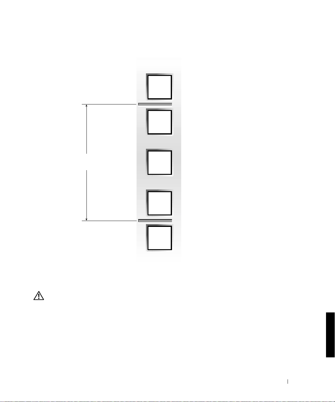
Figura 4-3. Unidad de rack
1-U (4,4 centímetros ó 1,75 pulg.)
12,7 mm (0,5 pulg.)
15,9 mm (0,625 pulg.)
15,9 mm (0,625 pulg.)
12,7 mm (0,5 pulg.)
Para obtener información acerca de los requisitos para el montaje de componentes en un
rack Dell, consulte al software Dell Rack Advisor, disponible en el sitio web de Dell, en
http://support.dell.com.
PRECAUCIÓN: si va a montar más de un sistema, instale las guías de montaje de modo
que el primer sistema se monte en la posición más baja disponible en el rack.
Para marcar el rack, realice los pasos siguientes:
1 Coloque una marca en las guías verticales frontales en las que desee colocar la parte
inferior del sistema que está instalando en el armario rack.
La parte inferior de cada espacio 1-U se encuentra en medio del espacio metálico má s
estrecho entre orificios (marcados con una línea horizontal en algunos armarios rack,
véase la figura 4-3).
Guía de montaje del rack 4-7
Page 78

2 Coloque una marca a 13,3 centímetros (5,25 pulgadas) por encima de la marca original
(o cuente nueve orificios en un bastidor que cumpla los estándares EIA-310) y marq ue
las guías verticales frontales del rack con un rotulador de punta de fieltro o coloque
cinta adhesiva donde vaya a situarse el borde superior del sistema (consulte la
figura 4-4).
Figura 4-4. Marcado de las guías verticales
www.dell.com | support.dell.com
3-U (5,25 pulgadas) entre
guías (el dibujo no está
realizado a escala)
puntos de cinta adhesiva
para la parte superior e
inferior del sistema
4-8 Guía de montaje del rack
Page 79

Instalación de las guías de montaje RapidRails
NOTA: si está montando las guías VersaRails, consulte “Montaje de las guías de montaje
VersaRails”.
En la parte frontal del armario rack, coloque una de las guías de montaje de forma que
1
la brida del soporte de montaje se ajuste perfectamente entre las marcas o cinta
colocada en el rack (consulte la figura 4-5).
2 Alinee la brida del soporte de montaje de la guía ( situada en la part e frontal de la g uía)
con los orificios cuadrados de las guías verticales frontales (consulte la figura 4-5).
3 Empuje sobre la guía hacia delante hasta que el gancho de montaje quede colocado en
los orificios cuadrados de la guía vertical y, a continuación, empuje hacia abajo la br ida
del soporte de montaje hasta que los ganchos de montaje se asientan en los orificios
cuadrados, y el pulsador azul salga y emita un clic.
Figura 4-5. Instalación de las guías de montaje RapidRails
pulsador azul
ganchos de montaje (2)
guía vertical frontal
parte delantera del rack
brida del soporte
de montaje
guías de montaje RapidRails (2)
Guía de montaje del rack 4-9
Page 80

4 En la parte posterior del armario, tire hacia atrás de la brida de soporte de montaje
hasta que los ganchos de montaje se coloquen en sus orificios cuadrados de la gu ía
vertical y, a continuación, empuje hacia abajo sobre la brida del soporte de montaje
hasta que los ganchos de montaje se asienten en los orificios cuadrados y el pulsador
azul salga y emita un clic.
5 Repita los pasos del 1 a 4 para la guía del otro lateral del rack.
6 Asegúrese de que las guías están monta das en la misma posició n en las guías vert icales
en cada lado del rack.
Instalación de las guías de montaje VersaRails
www.dell.com | support.dell.com
NOTA: si ya ha instalado las guías de montaje RapidRails, ignore esta sección.
1 En la parte frontal del armario rack, coloque una de las guías de montaje de forma que
la brida del soporte de montaje se ajuste perfectamente en el punto seleccionado en el
rack (consulte la figura 4-6).
Los orificios de las guías verticales del rack pueden ser redondos o cuadrados.
Figura 4-6. Instalación de las guías de montaje VersaRails
Los orificios de la guía
vertical pueden ser
redondos o cuadrados
parte delantera del rack
4-10 Guía de montaje del rack
orificios de montaje (2)
brida del soporte
de montaje
guías de montaje VersaRails (2)
Page 81

2 Empuje la guía de montaje hacia delante hasta que los orificios de montaje estén
alineados con los orificios de la guía vertical frontal.
3 Con dos tornillos Phillips 10-32 x 0,5, fije la brida del soporte de montaje frontal a la
guía vertical frontal.
4 En la parte trasera del armario, tir e hacia atrás de la br ida del sopor te de montaj e hasta
que quede alineada con los orificios de la guía vertical trasera.
5 Con dos tornillos Phillips 10-32 x 0,5, fije la brida del soporte de montaje trasera a la
guía vertical trasera.
6 Repita los pasos del 1 al 5 para la guía de montaje del otro lateral del rack.
7 Asegúrese de que las guías de montaje están montadas en la misma posición en las
guías verticales en cada lado del rack.
Montaje del kit de conversión de torre a rack
NOTA: si tiene una versión del sistema sólo en rack, ignore este procedimiento y pase
directamente a “Montaje del sistema en el rack ”.
PR ECAUCIÓN: el sistema puede tener una envergadura y un peso cons iderable.
A fin de evitar lesiones personales, no intente mover el sistema si n ayuda.
El kit de conversión de torre a rack incluye un panel frontal del rack con asas y tornillos de
mano.
Desmontaje del bisel, las unidades, las tapas y el panel frontal
1 Apague y desenchufe el sistema y desconecte los cables de alimentación y periféricos.
2 Para retirar el bisel (consulte la figura 4-7):
a Con la llave del sistema, desbloquee el bisel frontal.
b Gire el bisel del sistema hacia fuera y hacia abajo hasta que esté perpendicular al
sistema.
c Afloje los dos tornillos de mano que fijan la bisagra del bisel al panel frontal
(consulte la figura 4-7).
d Tire del bisel y colóquelo a un lado.
Guía de montaje del rack 4-11
Page 82

Figura 4-7. Extracción del bisel frontal
www.dell.com | support.dell.com
cierre
tornillo
de mano
bisel
3
Etiquete todas las unidades de disco duro y retírelas del sistema.
NOTA: aunq ue no es necesario para la conversión, quizás desee retirar los dos módulos de
alimentación y refrigeración de la parte posterior del c hasis del sistema p ara reducir el peso
del chasis mientras realiza este procedimiento (consulte la
de problemas
estos módulos).
Para retirar las tapas izquierda y derecha del sistema (consulte la figura 4-8):
4
a Retire las dos tapas redondas de la parte superior del sistema de torre.
b Utilice una llave de cabeza hexagonal (Allen) de 3/16 pulgadas para retirar los
tornillos hexagonales con encastre en cabeza y las arandelas planas de la parte
superior del sistema de torre.
c Deslice hacia atrás la tapa izquierda y derecha, lejos de la parte frontal del chasis
para desengancharla y tire las tapas hacia arriba, para retirarlas de la base.
4-12 Guía de montaje del rack
Guía de instalación y resolució n
del sistema para obtener instrucciones sobre la extracción y colocación de
Page 83

5 Para extraer la base del sistema de torre:
a Tumbe el sistema sobre su lado derecho.
b Utilice una llave de cabeza hexagonal (Allen) de 3/16 pulgadas para retirar los dos
tornillos hexagonales con encastre en cabeza y las arandelas planas de la base del
chasis de torre.
c Retire la base y colóquela a un lado (consulte la figura 4-8):
Figura 4-8. Extracción de la tapa del sistema de torre
tapas redondas (2)
tornillo hexagonal
con encastre (4)
arandela plana (4)
tapas derecha e izquierda
base
Guía de montaje del rack 4-13
Page 84

6 Para extraer el panel frontal del sistema de torre (consulte la figura 4-9):
a Coloque el sistema de forma que el panel frontal se coloque unos 2,5 centímetros
(1 pulgada) sobrepasando el borde de la mesa o la superficie de trabajo.
b Retire los tornillos T-10 Torx negros de cabeza cónica de 14 4-40 x 0,25 pulgadas
que fijan el panel frontal de la torre al chasis.
c Retire el panel frontal del chasis del sistema, teniendo cuidado para evitar dañar
los cinco tubos de plástico ligeros colocados a lo largo del panel frontal.
Montaje del panel frontal del rack
1 Coloque el panel frontal del rack en la parte frontal del chasis del sistema, y monte con
www.dell.com | support.dell.com
cuidado los cinco tubos ligeros en sus orificios del panel frontal.
NOTA: en el siguiente paso, coloque todos los tornillos Torx 14 T-10 en sus orificios antes
de apretar alguno de ellos para asegurar una alineación correcta.
2
Fije el panel frontal del rack al chasis con los tornillos Torx 14 T -10 quitados en el paso
6 del último procedimiento, “Desmontaje del bisel, las unidades, las tapas y el panel
frontal” (consulte la figura 4-9).
3 Vuelva a montar los módulos de alimentación y refrigeración (si se retiraron).
NOTA: no monte las unidades de disco duro hasta completar el procedimiento siguiente,
“Montaje del sistema en el rack”.
4-14 Guía de montaje del rack
Page 85

Figura 4-9. Montaje del panel frontal del rack
tornillos (14)
tubos ligeros (5)
panel frontal
Montaje del sistema en el rack
PR ECAUCIÓN: si va a montar más de un sistema, monte el sistema más pesado
en la posición más baja que haya dispon ible en el rack.
nunca
PRECAUCIÓN:
1
Levante el sistema hasta colocarlo frente a las guías de montaje instaladas en el
armario rack.
PR ECAUCIÓN: de bido al tamaño y el pes o del sistema, no intente nunca monta r
el sistema en las guías sin ayuda.
Inserte el sistema en el rack que el panel frontal esté colocado contra las guías
2
verticales (consulte la figura 4-10).
3 Apriete los tornillos de mano integrados en cada lado del panel frontal del sistema.
extraiga más de un componente del rack a la vez.
Guía de montaje del rack 4-15
Page 86

Figura 4-10. Montaje del sistema en el rack
www.dell.com | support.dell.com
tornillos de mano
integrados (2)
Colocación de las puertas en el rack
Consulte los procedimientos para volver a colocar las puertas en la documentación que se
facilita con los armarios rack Dell 24-U y 42-U. Si tiene un rack Dell PowerEdge 4210,
consulte los procedimientos indicados en la Guía de montaje del rack Dell PowerEdge 4210.
Si tiene un armario rack no fabricado por Dell, consulte la documentación del fabricante
para volver a colocar las puertas.
La conversión de montaje en rack de su sistema ya está terminada.
4-16 Guía de montaje del rack
Page 87

Índice
C
contenido del kit
ilustración, 4- 3 , 4 - 4
lista de componentes, 4-3
RapidRails, kit, 4-3
VersaRails, kit, 4-3
contenido del kit de rack, 4-3
ilustración, 4- 3 , 4 - 4
lista de componentes, 4-3
montar, 4-5
G
guías de montaje RapidRails
montar, 4-9
guías verticales
marcar, 4-8
unidad de rack, 4-7
H
herramientas
recomendadas, 4-5
I
información de seguridad, 4-4
M
marcar el rack, 4-6
montaje
tareas, 4-5
montar
guías de montaje
RapidRails, 4-9
guías de montaje
VersaRails, 4-10
kit de torre a rack, 4-1 1
panel frontal del rack, 4 -14
sistema en rack, 4 -15, 4-16
P
puertas
desmontaje, 4-6
volver a colocar, 4-16
R
rack
marcar, 4-6
pie estabilizador, 4-5
rack que no sea de Dell
requisitos, 4- 4
RapidRails
contenido del kit, 4-3
requ i s i t o s
rack Dell, 4-3
rack que no sea de Dell, 4-4
Requisitos para rac ks
Dell, 4-3
S
sistema
montar en rack, 4-15, 4-16
sitio web de Dell, 4-7
T
torre a rack
montar, 4-11
U
unidad de rack, 4-7
V
VersaRails
contenido del kit, 4-3
Requisitos para racks que no
sean Dell, 4-4
Índice 1
Page 88

2 Índice
Page 89

Dell™ システム
ラック取り付けガイド
www.dell.com | support.dell.com
Page 90

メモ、注意、警告および危険
メモ : メモは、コンピュータを使いやすくする為の重要な情報を説明しています。
注意 : 注意は、ハードウェアの損傷やデータの損失の可能性があることを示し、その危険
を回避するための方法を説明しています。
警告 : 警告は、問題を回避しないと、身体に危険を及ぼす可能性があることを示します。
危険 : 危険は、問題を回避しないと、身体に重大な損害を与える可能性や死に至る危険性
があることを示します。
ここに記載されている内容は予告なく変更されることがあります。
© 2001 年すべての著作権は Dell Computer Corporation にあります。
Dell Computer Corporation の書面による許可のない複写は、いかなる形態においても厳重に禁じられていま
す。
本書で使用されている商標について:
Computer Corporation
本書では、必要に応じて上記記載以外の商標および会社名が使用されている場合がありますが、
標や会社名は、一切
2001 年 9 月 P/N 7F206 Rev. A00
の商標です。
Dell Computer Corporation に所属するものではありません。
Dell、DELL ロゴ、PowerEdge、RapidRails、および VersaRails は Dell
これらの商
Page 91

目次
安全にお使いいただくための注意 . . . . . . . . . . . . . . . . . . . . . . . . . 5-1
インストールガイド . . . . . . . . . . . . . . . . . . . . . . . . . . . . . . . . . . . . 5-2
RapidRails ラックキットの内容 . . . . . . . . . . . . . . . . . . . . . . . . . . 5-3
Dell ラックの要件 . . . . . . . . . . . . . . . . . . . . . . . . . . . . . . . . . . . . . . 5-3
VersaRails ラックキットの内容 . . . . . . . . . . . . . . . . . . . . . . . . . . 5-3
Dell 以外のメーカーのラックの要件 . . . . . . . . . . . . . . . . . . . . . . 5-4
はじめに . . . . . . . . . . . . . . . . . . . . . . . . . . . . . . . . . . . . . . . . . . . . . 5-4
安全に関する重要な注意 . . . . . . . . . . . . . . . . . . . . . . . . . . . . . . . . 5-4
ラック安定用の脚 . . . . . . . . . . . . . . . . . . . . . . . . . . . . . . . . . . . . . . 5-5
推奨する工具および備品 . . . . . . . . . . . . . . . . . . . . . . . . . . . . . . . . 5-5
取り付け手順 . . . . . . . . . . . . . . . . . . . . . . . . . . . . . . . . . . . . . . . . . . 5-5
ラックの扉の取り外し . . . . . . . . . . . . . . . . . . . . . . . . . . . . . . . . . 5-6
索引
ラックに印を付ける . . . . . . . . . . . . . . . . . . . . . . . . . . . . . . . . . . . 5-6
RapidRails 取り付け用レールの取り付け . . . . . . . . . . . . . . . . . . . 5-9
VersaRails 取り付け用レールの取り付け . . . . . . . . . . . . . . . . . . 5-10
タワー - ラック転換キットの取り付け . . . . . . . . . . . . . . . . . . . . . 5-11
ベゼル、ドライバ、カバー、正面パネルの取り外し . . . . . . . 5-11
ラック正面パネルの取り付け . . . . . . . . . . . . . . . . . . . . . . . . . . . 5-14
ラックへのシステムの取り付け . . . . . . . . . . . . . . . . . . . . . . . . . . 5-15
ラックの扉の取り付け . . . . . . . . . . . . . . . . . . . . . . . . . . . . . . . . 5-16
目次 3
Page 92

図
図 5-1 RapidRails ラックキットの内容 . . . . . . . . . . . . . . . . . . . 5-3
図 5-2 VersaRails ラックキットの内容 . . . . . . . . . . . . . . . . . . . 5-4
図 5-3 ラックの 1-U. . . . . . . . . . . . . . . . . . . . . . . . . . . . . . . . . . . . 5-7
図 5-4 垂直レールに印を付ける . . . . . . . . . . . . . . . . . . . . . . . . . 5-8
図 5-5 RapidRails 取り付け用レールの取り付け . . . . . . . . . . . 5-9
図 5-6 VersaRails 取り付け用レールの取り付け . . . . . . . . . . 5-10
図 5-7 正面ベゼルの取り外し . . . . . . . . . . . . . . . . . . . . . . . . . . 5-12
図 5-8 タワーシステムカバーの取り外し . . . . . . . . . . . . . . . . 5-13
図 5-9 ラック正面パネルの取り付け . . . . . . . . . . . . . . . . . . . . 5-15
図 5-10 ラックへのシステムの取り付け . . . . . . . . . . . . . . . . . . 5-16
4 目次
Page 93

安全にお使いいただくための注意
ご自身の身体の安全を守り、サーバ、ストレージシステム、アプライアンスを損傷か
ら保護するために、以下の点にご注意ください。安全、規則、保障の詳細について
は、ご利用の
ラックに設置可能な製品に対する注意点
ラックの安定性や安全性に関し て、次の点にご注意ください。特定の警告や注意文
および手順については、システムやラックに同梱されているラック取り付 けマニュ
アルを参照してください。
サーバ、ストレージシステム、およびアプライアンスは、ラックに取り付ける部品
とみなします。したがって
ライアンス、および各種周辺装置またはサポートハードウェアを意味します。
警告 : ラック正面および横の安定板を取り付けずにラックにシステム部品を取り付ける
と、ラックが転倒し、けがをしたり死に至る恐れがあります。したがって、必ず安定板
を取りつけてからラックに部品を取り付けてください。
警告 : ラックにシステム / 部品を取り付けた後は、一度に 2 台以上の部品を、スライドア
センブリのラックから引き出さないでください。重みでラックが転倒し、けがをする恐
れがあります。
メモ : お使いの Dell システムは、独立型のユニットとして、また、Dell カスタマラック
キットで構成される Dell のラックキャビネットに取り付ける部品として、その安全性を
保証されています。Dell 以外のメーカーのラックキャビネットに Dell のシステムやラッ
クキットを取り付けることは、どの安全機関でも承認されていません。Dell 以外のメー
カーのラックキャビネットで Dell のシステムやラックキットを最終的に組み合わせて使
用する場合は、ユーザーが責任を持って 認定安全機関で適合性の評価を受け てくださ
い。Dell は、上記の組み合わせに関する一切の責任および保証を否認します。
Dell™ システムの『システム情 報』マ ニュア ルを参 照して くださ い。
「部品」の用語は、サーバ、ストレージシステム、アプ
• システムラックキットは、トレーニングを受けたサービス技術者が Dell のラッ
クに取り付けます。キットを別のラックに取り付ける場合は、そのラックが
Dell のラック仕様に適合するかを確認してください。
• 大型ラックを 1 人で移動しないでください。ラックの高さと重さを考慮して 、
少なくとも
2 人以上でラックを移動することをお勧めします。
• ラックを移動する前に、安定板がラックに固 定されて床面に伸び、ラックの全
重量が床面にかかっていることを確認してください。ラックを移動する前に、
つのラックの場合は正面と横の安定板、複数の組み合わされたラックの場合は
正面の安定板を取り付けます。
ラック取り付けガイド 5-1
1
Page 94

• ラックには必ず下から上の順に、最も重いものから設置します。
• 部品をラックから引き出す前に、ラックが平行で安定していることを確認して
ください。
• 部品レールリリースラッチを押し、部品をラックの中または外にスライドする
場合はご注意ください。スライドレールに指をはさまれることがあります。
• 部品をラックに設置したら、レールをロック位置に静かに伸ばし、部品をラッ
クの中にスライドします。
• ラックに電力を送る AC 分岐回路に過重電流を流さないでください。ラックの
総負荷が分岐回路定格の
www.dell.com | support.dell.com
• ラックの部品に空気が充分に送られていることを確認します。
• ラックの他のシステム/部品を取り扱っているときに、システム/部品の上に乗っ
たり、立ってはいけません。
80 パーセントを超えないようにしてください。
インストールガイド
このガイドは、ラックキャビネットに 1 つまたは複数のシステムを取り 付ける作業
を行う、トレーニングを受けた サービス技術者向けの手順書です。
クキットはすべての
的なほとんどのラックキャビネットに取り付けることができます。
VersaRails ラックキットの取り付け手順はほとんど同じです。ラックキャビネットに
取り付けるシステム
Dell™ ラックキャビネットに、VersaRails™ ラックキットは標準
1 基ごとにラックキット 1 セットが必要です。
RapidRails™ ラッ
RapidRails および
警告 : 別のシステム用に設計されたラックキット部品は取り 付け ない でく ださ い。ご使 用
のシステムに対応したラックキット のみ を使用 してく ださ い。別のシステム用のラック
キットを使用すると、システムが損傷し、ご自身や関係者がけがをする恐れがあります。
メモ : タワーバージョンのシステムを使用している場合は、最初にタワーラック転換
キットを取り付けてラックバージョンに転 換する必 要があり ます。このキットの取り付
け手順は本書で説明しています。
5-2 ラック取り付けガイド
Page 95

RapidRails ラックキットの内容
RapidRails ラックキットは、1 組の RapidRails 取り付け用レールで構成されています
( 図 5-1 参照 )。
図 5-1. RapidRails ラックキットの内容
RapidRails 取り付け用レール
Dell ラックの要件
注意 : 本ラックキットは、トレーニングを受けたサービス技術者が Dell ラックに取り付
けます。ほかのラックにこのキットを取り 付け るときは、かならず、そのラックが米国
規格協会 (ANSI) / 米国 電子工業会 (EIA) 規 格 ANSI/EIA-310-D-92、国際電気標準会 議
(IEC) 297、ドイ ツ 工業規格 (DIN) 41494 の仕様に適合していることを確認してくださ
い。ラックに取り付けるシステム 1 基ごとにラックキット 1 セットが必要です。
VersaRails ラックキットの内容
VersaRails ラックキットの内容は次のとおりです ( 図 5-2 参照 )。
•VersaRails 取り付け用レール 1 組
• 10-32 x 0.5 インチプラスネジ 8 個
メモ : 図と手順で示されているメートル法規格ではないネジは、サイズとインチ当たり
ねじ山数 で表記されていま す。たとえば、インチ当たりねじ山数 32 の #10 プラ スねじ
は、10-32 の表記になります。
ラック取り付けガイド 5-3
Page 96

図 5-2. VersaRails ラックキットの内容
10-32 x 0.5 インチの
ナベプラスネジ (8)
www.dell.com | support.dell.com
VersaRails 取り付け用レール
Dell 以外のメーカーのラックの要件
注意 : 本ラックキットは、トレーニングを受けたサービス技術者が米国規格協会 (ANSI)/
米国電子工業会 (EIA) 規格 ANSI/EIA-310-D-92、国際電気標準会議 (IEC) 297、ドイツ工
業規格 (DIN) 41494 に適合したラックに取り付けます。ラックに取り付けるシステム 1 基
ごとにラックキット 1 セットが必要です。
はじめに
システムをラックに取り付ける 前に、本書の冒頭にある「安全にお使いいただく た
めの注意」をお読みください。また、『システム情報』マニュアルの「安全にお使
いいただくための注意」も参照してください。
警告 : 複数のシステムをラックに取り付ける場合は、1 基のシステムの手順を完了して
から、次のシステムの取り付けに進んでください。
安全に関する重要な注意
システムをラックに取り付ける場合は、次の各セクション の安全上の注意 に従って
ください。
警告 : 作業者は、自分自身と関係者を保護するために、本書の手順を遵守する必要があ
ります。システムは非常に大きく相当 な重量があります。自分自身と関係者のけがを防
ぐために、きちんと準備をして計画的に作業を進める必要があります。これは、特にシ
ステムをラックの高い位置に取り付ける場合に重要になります。
5-4 ラック取り付けガイド
Page 97

ラック安定用の脚
警告 : ラック正面および横の安定用の脚を取り付けずに、また安定用の脚を床に固定せ
ずにラックにシステムを取り付け ると、ラックが転倒し、けがをしたり死に至る恐れが
あります。したがって、安定用の脚を取り付けて床に固定してから、ラックに部品を取
り付けてください。
警告 : ラックにシステムを取り付けた後で、一度に複数のシステムをラックから引き出
さないでください。引き出された複数のシステムの重みでラック が転倒し、けがをする
恐れがあります。
安定用の脚は、ラックからシステムやその他の部品を引き出す際にラックの転倒を
防ぎます。安定用の脚を取り付けて床に固定する手順については、ラックキャビ
ネットに付属のマニュアルを参照してください。
推奨する工具および備品
以下のような工具を使用すると、取り付け作業をスムーズに進めることができます。
• #2 プラスドライバ (VersaRails キットを取り付ける場合 )
• Torx T-10
• 3/16
ドライバ ( タワーラックキットを取り付ける場合 )
インチ六角レンチ ( タワーラックキットを取り付ける場合 )
取り付け手順
ラックキットの取り付けでは、以下のような作業を行います。
1 ラックの扉の取り外し
2 ラックに印を付ける
3 ラックへの取り付け用レールの取り付け
4 タワーラック転換キットの取り付け ( 必要な場合 )
5 ラックへのシステムの取り付け
6 ラックの扉の取り付け
メモ : 以下の手順は、特に指定がない限り、Dell のラックキャビネットと Dell 以外の
メーカーのラックキャビネットの両方に適用されます。
ラック取り付けガイド 5-5
Page 98

ラックの扉の取り外し
扉を取り外す手順については、Dell 24-U および 42-U ラ ックキャビネットに付属のマ
ニュアルを参照してください。
『
Dell PowerEdge 4210 ラック取り付けガイド』を参照してください。Dell 以外の
メーカーのラックキャビネットの場合は、メーカーのマニュアルを参照して扉を取
り外してください。
警告 : ラックキャビネットの扉の大きさと重さを考慮して、取り付けまたは取り外しは 1
人では行わないでください。
Dell PowerEdge™ 4210 ラックキャビネットの場合は、
www.dell.com | support.dell.com
ラックに印を付ける
メモ : VersaRails ラックキットを取り付ける場合は、「VersaRails 取り付け用レールの取
り付け」の手順に進んでください。
ラックに取り付けるシステムごとに 3-U (5.25 インチ ) の垂直スペースが必要です。
Dell のラックキャビネットと EIA-310 規格に適合している Dell 以外のメーカーの
ラックキャビネットの前後の垂直レールには、
けられています。
隔は、
15.9 mm、15.9 mm、12.7 mm (0.625 インチ、0.625 インチ、0.5 インチ ) となっ
ています
( 図 5-3 参照 )。
1-U スペースの一番上の穴を起点とした穴の中心から中心までの間
1-U ごとに 3 つの穴が一定の間隔で開
5-6 ラック取り付けガイド
Page 99

図 5-3. ラックの 1-U
1-U (4.4 cm または 1.75 インチ )
12.7 mm (0.5 インチ )
15.9 mm (0.625 インチ )
15.9 mm (0.625 インチ )
12.7 mm (0.5 インチ )
Dell ラックに部品を取り付ける際の要件については、Dell Rack Adviso r ソフトウェア
で詳しく説明しています。ソフトウェアは
Dell の Web サイトで入手できます。
http://support.jp.dell.com
警告: 2 基以上のシステムを取り付ける場合は、ラックの最下段に 1 基目のシステムを取
り付けられるように取り付け用レールをセットしてください。
ラック取り付けガイド 5-7
Page 100
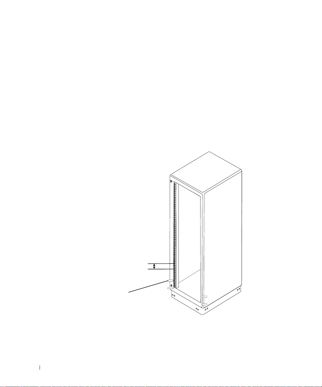
次の手順に従って、ラックに印を付けます。
1 前部垂直レール上で、ラックキャビネットに取り付けるシステムの底部の位置
を決め、印を付けます。
1-U スペースの底部は、間隔が狭い 2 つの穴の間にある金属部分の真ん中にな
ります
ます。図
2 初めの印から 13.3 cm (5.25 インチ ) 上の位置 (EIA -31 0 規格に適合するラックの
場合は
が収まる位置を 確認し、マジックペンやマスキングテープで印を付けます
www.dell.com | support.dell.com
5-4 参照 )。
図 5-4. 垂直レールに印を付ける
(ラックキャビネットによっては水平なラインが刻まれている場合があり
5-3 を参照してください )。
9 個上の穴 ) に印を付けます。次に、前部垂直レール上でシステムの上 部
( 図
レールの間隔は 3-U (5.25
インチ ) ( 図は実際の寸法
とは異なります )
システムの上部と底部の
位置を示すテープの印
5-8 ラック取り付けガイド
 Loading...