

Page 1

Contents: Dell PowerVault 160T Tape Library User's Guide
Dell™ PowerVault™ 160T Tape Library User's Guide
Introduction
Getting Started
Understanding the User Interface
Working With Cartridges and Barcodes
Configuring the Library
Running Your Library
Frequently Asked Questions
Maintaining Your Library
Troubleshooting
Getting Help
Contacting Dell
Specifications
Information in this document is subject to change without notice.
© 2003 Dell Inc. All rights reserved.
Reproduction in any manner whatsoever without the written permission of Dell Inc. is strictly forbidden.
Trademarks used in this text: Dell, the DELL logo, and PowerVault are trademarks of Dell Inc. Microsoft, Windows NT, and
Windows are registered trademarks of the Microsoft Corporation. UNIX is a registered trademark of The Open Group of the
United States and other countries. Red Hat is a registered trademark of Red Hat, Inc.
Other trademarks and trade names may be used in this document to refer to either the entities claiming the marks and
names or their products. Dell Inc. disclaims any proprietary interest in trademarks and trade names other than its own.
Initial release: August 2003
file:///C|/Users/greshma_dhanarajan/Desktop/ug/index.htm[5/16/2013 10:08:12 AM]
Page 2

Introduction: Dell PowerVault 160T Tape Library User's Guide
Back to Contents Page
Introduction: Dell™ PowerVault™ 160T Tape Library
User's Guide
Other Documents You Might Need Control Module
Explanation of Symbols Expansion Modules
Obtaining Technical Assistance Host Attachment
Description Management
Features
This manual contains information and instructions necessary for the operation of the PowerVault 160T Tape Library.
Other Documents You Might Need
PowerVault 160T Unpacking Instructions (Dell Service only)
PowerVault 160T Installation Guide (Dell Service only)
The System Information Guide provides important safety and regulatory information. Warranty information may be
included within this document or as a separate document.
Explanation of Symbols
The following symbols and highlighted passages note important information:
Symbol Description Definition
CAUTION: A CAUTION indicates a potential for property damage, personal injury, or death.
NOTICE: A NOTICE indicates either potential damage to hardware or loss of data and tells you how to
avoid the problem.
NOTE: A NOTE indicates important information that helps you make better use of your storage device.
Obtaining Technical Assistance
Dell Enterprise Training and Certification is now available; see www.dell.com for more information. This service may not be
offered in all locations.
Description
The Dell PowerVault 160T Tape Library automates the retrieval, storage, and control of cartridge tapes. Cartridges are
mounted and retrieved in tape drives using application software from the host without operator intervention.
The library has a standard 19-inch rack footprint and can be placed in a typical server rack space. All functions are accessible
from the front and back doors. The library can be installed on a solid or a raised floor.
file:///C|/Users/greshma_dhanarajan/Desktop/ug/intro.htm[5/16/2013 10:08:13 AM]
Page 3

Introduction: Dell PowerVault 160T Tape Library User's Guide
The smallest configuration consists of one control module. As storage and tape drive requirements change, you can scale from
264 LTO tapes to 1,344 LTO tapes and up to 48 LTO drives by adding expansion modules to the control module. These
numbers vary by drive type. A fully expanded library with one control module and three expansion modules shares a single,
barrier-free robotics system that eliminates the need for pass-through ports, see Figure 1
Figure 1. Dell PowerVault 160T Tape Library (Front View)
.
Features
The following subsections describe the features of the Dell PowerVault 160T:
Scalability
Your library can consist of a single control module, which makes about 264 storage cells available. You can add up to three
expansion modules, with 350 or more storage slots per module for an overall storage maximum of 1344 cartridges.
Density
This library provides a storage density of 720 LTO cartridges per square meter. Storage density numbers vary by drive type.
Each module, or frame, has two storage racks, a rack on the drive side and a rack on the door side. Each storage rack has
ten sections. The size of a section is the size of the magazine for a particular media type. For LTO, for example, there are six
rows per section. Four columns, each the width of a section, are distributed across the rack.
file:///C|/Users/greshma_dhanarajan/Desktop/ug/intro.htm[5/16/2013 10:08:13 AM]
Page 4

Introduction: Dell PowerVault 160T Tape Library User's Guide
Centralized Management
The Library Management Console gives you a single point from which to view all library components: robotics, drives, and
network connectivity. This graphical user interface can be run both locally and remotely. It uses a simple, intuitive graphical
style that is both secure and powerful. It provides library managers with native partitioning ability and a rich SNMP-based
policy engine.
Proactive Availability
The library can alert you of problems before they occur. The complete data path is checked at user-defined intervals in order
to ensure that it is functioning before backup begins. The six major subsystems-drives, power, robotics, cooling, connectivity,
and control-are all monitored by the system. Notifications of problems can be configured to be sent to the Library
Management Console client, to an e-mail account, or directly to Dell support personnel. For more information on the
monitoring and reporting capabilities of the library, refer to Maintaining Your Library
.
Reliability
The library has industry leading reliability features. The drives, power supplies, and fans are all hot swappable. Redundant
power supplies are standard.
Your backup system and path sit idle most of the time. When backup begins, the system is used intensively at maximum
bandwidth. Since you have the benefit of the proactive alerts that the library issues, you know that any problems have been
identified and solved before backup begins. For more information about reliability features of the library, refer to
Troubleshooting
.
SAN Backup
Storage networking support is built into the library. Fibre Channel throughput results in huge amounts of data being quickly
and safely stored.
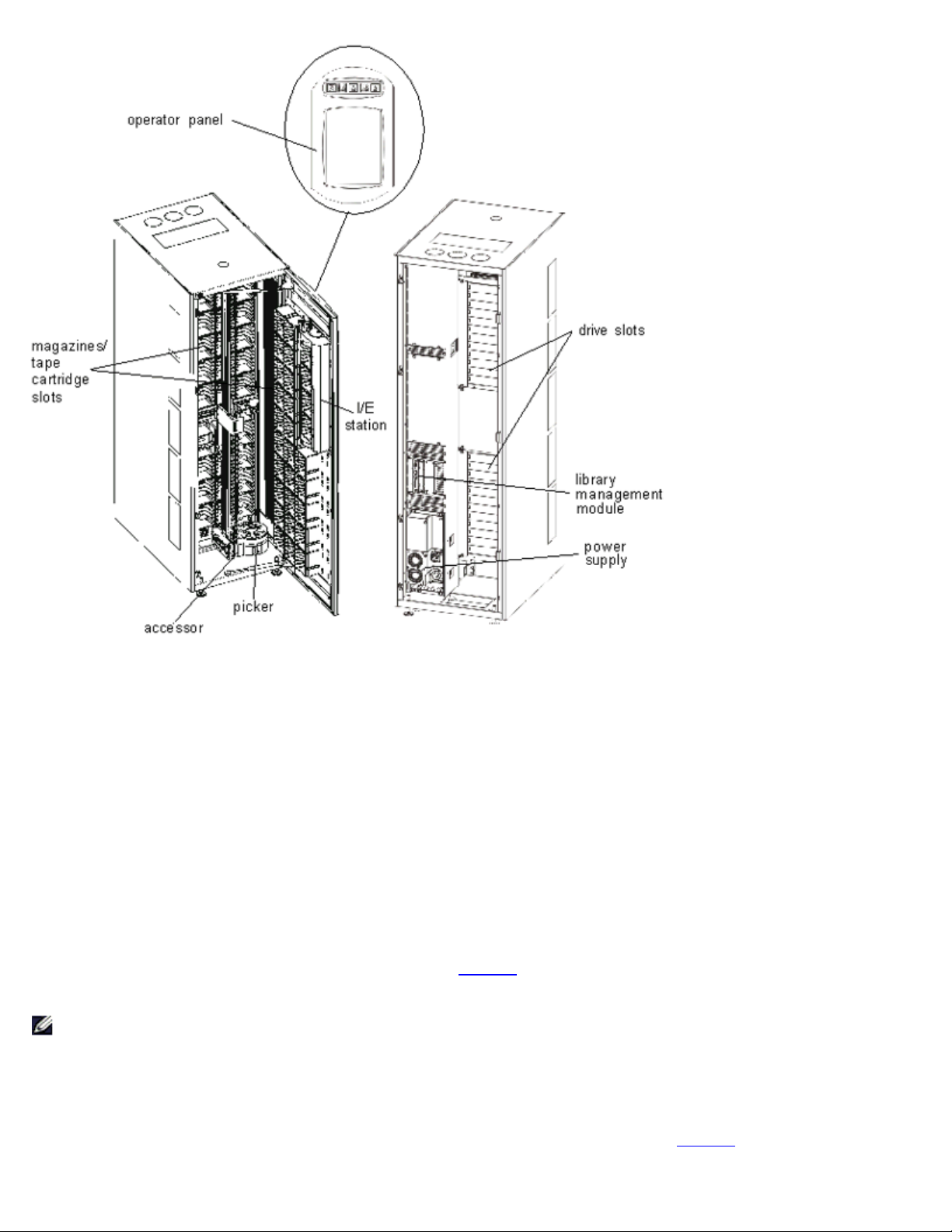
Control Module
The control module is a required library component. It contains the following components (see Figure 2):
Library management module
Cartridge accessor
Import/Export station
Tape magazines
Tape cartridge slots
Tape drives
Operator panel
Power
Figure 2. Control Module (Internal View)
file:///C|/Users/greshma_dhanarajan/Desktop/ug/intro.htm[5/16/2013 10:08:13 AM]
Page 5
Introduction: Dell PowerVault 160T Tape Library User's Guide
Library Management
Control of the library originates in the library management module. It manages system hardware and allows external devices
to configure the library and to obtain system status.
Cartridge Accessor
The cartridge accessor moves cartridges between storage cells, tape drives, and the I/E station. A picker is used to get or put
cartridges in a storage cell or a tape drive slot. The picker moves along an X and Y axis and can pivot 180o. A barcode
scanner on the picker assembly identifies cartridges and storage cells.
Import/Export Station
The I/E station allows you to import and export cartridges without interrupting normal library operation. The I/E station is
located on the front of the control or expansion module. See Figure 1
located in four removable magazines. Capacity varies by drive type.
NOTE: The I/E station cannot be configured as a storage location
. Each I/E station has a capacity of 24 LTO cartridges
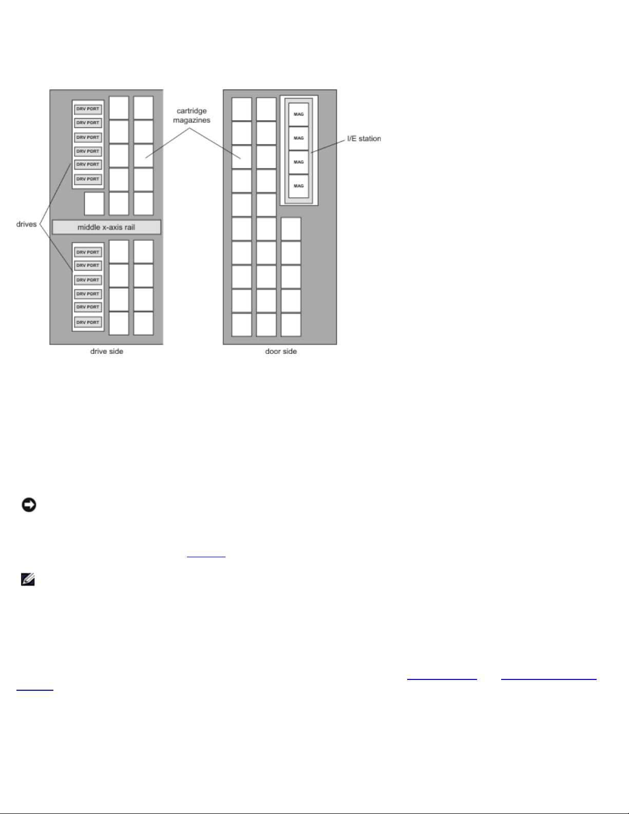
Cartridge Magazines
The cartridge magazine is a storage assembly located on the drive or door side of the control or expansion module. The
control module can house a maximum of 264 LTO slots. Capacity varies by drive type. See Figure 3
.
file:///C|/Users/greshma_dhanarajan/Desktop/ug/intro.htm[5/16/2013 10:08:13 AM]
Page 6
Introduction: Dell PowerVault 160T Tape Library User's Guide
Each tape magazine has a barcode label that the barcode scanner reads for identification and inventory. An optional, snap-on
dust cover is available for the magazines. The magazines with the dust cover have interlocked stacking for external media
storage.
Figure 3. Magazine and Drive Locations
Tape Cartridges
Tape cartridges are stored in magazines within the library and are identified by an operator-attached, machine-readable
barcode label. The library currently supports Code 39 type labels. The barcode label can have up to 16 characters.
Tape Drives
The library supports IBM LTO-1 or LTO-2 FC Multimode tape drives
NOTICE: The Dell PowerVault 160T does not support mixing drive types. This includes mixing LTO-1 and LTO-2 drives.
The control module has an upper and a lower drive cluster. The control module must include at least one tape drive. Each
drive cluster can house up to six full-height, tape drives for a total of 12 drives. Drives are installed from bottom to top in the
lower and upper drive clusters. See Figure 3
NOTE: The term drive cluster defines a grouping of up to six tape drives above or below the middle x-axis rail.
The tape drives are enclosed in a universal drive sled. You can hot swap all drives.
.
Operator Panel
The operator panel is located on the front of the control module and consists of the button/indictors and the touch screen. For
more information on the operator panel and Library Management Console, refer to Operator Panel
Console.
and Library Management
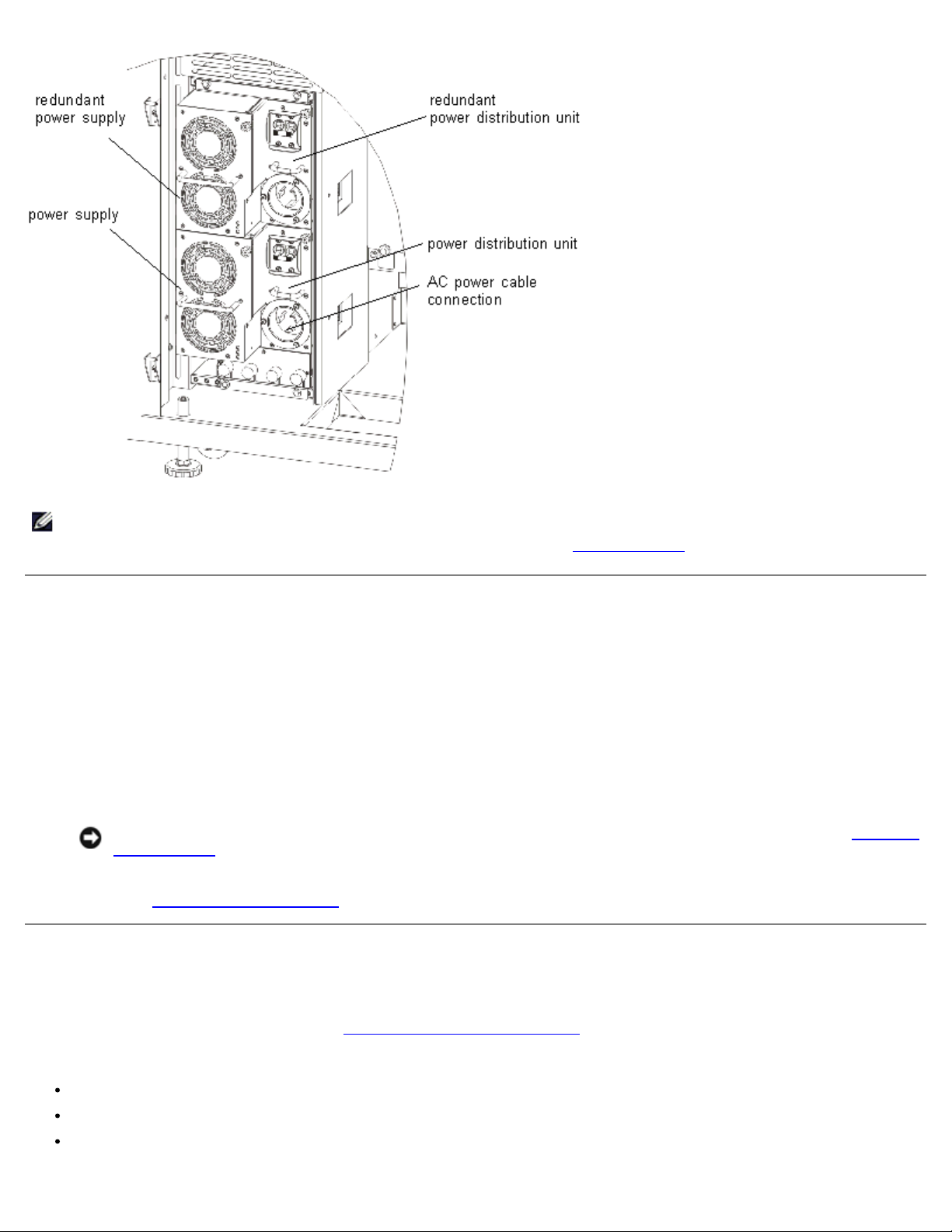
Power System
The library supports a redundant power configuration. This configuration has dual AC line input and dual DC power supplies.
Redundant power configuration means you can hot swap a power supply.
file:///C|/Users/greshma_dhanarajan/Desktop/ug/intro.htm[5/16/2013 10:08:13 AM]
Page 7
Introduction: Dell PowerVault 160T Tape Library User's Guide
The power system consists of the following:
Power supply
Power distribution unit (PDU)
AC power cord
A single power switch, located on the front door, turns on and off all power for the control module and attached expansion
modules. Each PDU has a second circuit breaker, located in the rear of the module, that controls the module power supply
output. The power supply has three LEDs that provide status information. The power system also has four fuses for system
protection.
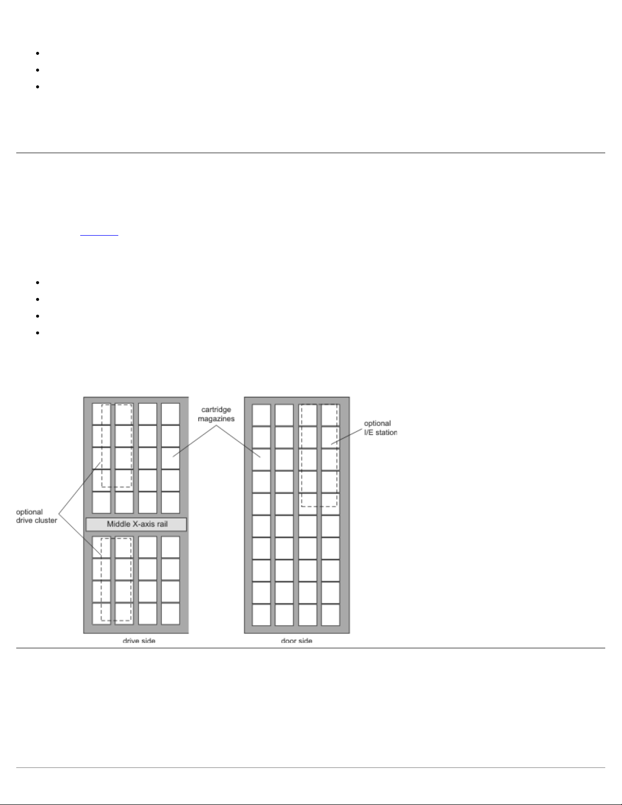
Expansion Modules
Expansion modules allow the library to expand to accommodate additional tape drives and cartridge capacity. Each expansion
module adds up to 360 LTO storage slots depending on the number of tape drives ordered and if an optional I/E station is
installed, see Figure 4
modules.
The expansion module can accommodate the following functional units:
Tape drives
Cartridge storage cells
I/E station (optional)
Redundant AC power compartment
. Capacity varies by drive type. The library's maximum configuration includes up to three expansion
Power supplies are not required in the expansion module unless the expansion module has tape drives. If an expansion
module contains only cartridges, all power is derived from the control module.
Figure 4. Expansion Module
Host Attachment
Requests issued from the host application result in cartridge movement in the library. The primary requests issued are for
mounting and dismounting cartridges in and out of the tape drives and for importing and exporting cartridges in and out of
the library. The library manages the physical location. In addition to requesting cartridge movement in the library, the host
application can obtain status, configuration information, and cartridge storage information stored in the library.
Hosts can be directly attached to drives or they can be attached to a switch, which is then attached to the drives.
file:///C|/Users/greshma_dhanarajan/Desktop/ug/intro.htm[5/16/2013 10:08:13 AM]
Page 8

Introduction: Dell PowerVault 160T Tape Library User's Guide
Management
The library can be managed locally or remotely using the Library Management Console (LMC). Locally, the LMC is displayed on
the touch screen on the front of the library. Remotely, the LMC is accessed through a client instance of the SNC Manager
software on any computer on the network. The local and remote LMC user interfaces are identical. For more information on
the LMC, see Library Management Console
Back to Contents Page
.
file:///C|/Users/greshma_dhanarajan/Desktop/ug/intro.htm[5/16/2013 10:08:13 AM]
Page 9

Getting Started: Dell PowerVault 160T Tape Library User's Guide
Back to Contents Page
Getting Started: Dell™ PowerVault™ 160T Tape Library
User's Guide
Cabling
Installing Cartridges
Installing Tape Drives
Applying Power
Logging on Locally
Running the Setup Wizard
Installing a Remote Client
Cabling
The controlling host computer(s) connect directly to the drives and library. The management control blade (MCB) that is
located in the control module controls library operation. The MCB has one library control port (SCSI or Fibre Channel)
connecting to the controlling host computer. The MCB SCSI control port provides its own termination. Drives attach directly to
host computers and are represented by their own unique SCSI ID or World Wide Name and LUN ID. The user interface client
software communicates via an Ethernet connection to the localized server and agent running on the MCB.
A typical cabling scheme is shown in Figure 1
NOTE: Cabling may be affected by partitioning or zoning changes. When cabling to drives, ensure that they are cabled
to the correct hosts for the defined partitions.
Figure 1. Direct Attached Library With Fibre Drives
.
file:///C|/Users/greshma_dhanarajan/Desktop/ug/getstart.htm[5/16/2013 10:08:14 AM]
Page 10

Getting Started: Dell PowerVault 160T Tape Library User's Guide
Cable management is accomplished through velcro clamps on the right-hand side of the library and a horizontal routing
guide. Install the cables through these cable management devices.
Host Connection Considerations
There are limitations on the number of hosts that can access a single drive at any one time, for example, Fibre Channelattached drives support a minimum of two initiators.
The Ultrium tape drive model T200F (Fibre Channel drive) is an arbitrated-loop-only device (also known as an NL port). The
drive supports Fibre Channel Arbitrated Loop (FC-AL) protocol, and uses Class 3 Service frames. The drive also supports both
public (switch-attached) and private loops.
The library uses a LUN ID which is configured by using the Library Management Console FC Host and SCSI Host commands.
Library partitions as well as drives are presented as devices to be mapped. SCSI IDs or cabling may affect which SCSI device
map LUN is associated with which FC Host or SCSI Host LUN ID. Ensure that the device order is not altered when swapping
drives, cables, or locations.
NOTE: The partition should map to a higher priority LUN than the drives.
Installing Cartridges
Before handling data cartridges, review the guidelines in Working with Cartridges and Barcodes.
Cartridges can be loaded into the library in two ways:
With the front door open, manually insert data cartridges in the desired location in the appropriate magazine.
With the front door closed, manually insert tape cartridges in the I/E station and use the Library Management Console
to import the cartridges.
NOTICE: If you have configured more than one partition, use the I/E station to import cartridges.
When installing cartridges:
Make certain the barcode side is facing out of the slot. All cartridges must be labeled with a valid barcode label.
Make certain that the cartridge is completely seated in the slot. Accessor motion can be impeded if the cartridge is not
completely seated within the slot.
Make sure that the media is not inserted in the slot upside down (see Figure 2).
Figure 2. Cartridge in Magazine
file:///C|/Users/greshma_dhanarajan/Desktop/ug/getstart.htm[5/16/2013 10:08:14 AM]
Page 11

Getting Started: Dell PowerVault 160T Tape Library User's Guide
Installing Tape Drives
The library can contain up to 12 full-height and 24 half-height tape drives. Tape drives should be added moving bottom to
top starting with the lower drive cluster (see Figure 3
bottom position in the upper drive cluster.
Figure 3. Drive Installation Locations
). When the lower drive cluster is filled, begin adding tape drives to the
Required tools: 2.5 mm hex wrench, Phillips screwdriver
1. Open the front door.
2. Using a 2.5 mm hex wrench, unscrew the retaining screws (2 screws per plate) that secure the cover plate(s) over the
target drive slot.
3. Close the front door.
4. Open the back door.
5. In the corresponding drive location, using the Phillips screwdriver or your fingers, unscrew the one retaining
thumbscrew and remove the corresponding drive cover plate(s).
6. Using the markings on the drive slot, install the drive slowly so the guide rails engage. The installed drive should be
flush with no gaps above or below it.
Use the bottom of the empty drive cluster as a guide if you are installing a drive in the Drive 1 or Drive 7 position. If a
drive is installed below the slot where you are adding a drive, use the top of the drive below as a guide. For example, if
you are adding a drive in Drive 9, use the drive in Drive 8 as a guide.
Figure 4. Fibre Channel Tape Drive
file:///C|/Users/greshma_dhanarajan/Desktop/ug/getstart.htm[5/16/2013 10:08:14 AM]
Page 12

Getting Started: Dell PowerVault 160T Tape Library User's Guide
9. Using the Phillips screwdriver or your fingers, tighten the two retaining thumbscrews.
10. Install any further tape drives in the lower drive cluster. When the lower cluster is full, install the next tape drive in the
upper drive cluster.
11. Close the back door.
Applying Power
Before applying power, you should perform a voltage check.
Required tools: digital volt meter
1. If the outlet case is conductive (metal), measure for 0 VAC from building ground to the outlet case.
2. Measure for 0 VAC from the ground pin of the outlet to the building ground.
3. Measure for less than 1 ohm resistance from the ground pin of the outlet to building ground and from the ground pin of
the machine power cord to each module in the library.
4. Measure the supplied voltage. The nominal voltage is single-phased 110/220 VAC for the control module and 110/220
VAC for the expansion modules. Perform this measure for all outlets (one for each module).
5. Connect the ground wire, from the ground source to the ground point located on the control module (the ground point
is marked with a ground symbol).
In Europe, use an industrial type plug that meets the IEC 309 requirement.
Turning on the Library
1. Plug the AC power cable(s) into the power distribution unit(s).
2. Plug the AC power cable(s) into a power source(s).
3. On the power distribution unit(s), set the circuit breaker switch labeled Power to the up (I) position. Fan power
supplies will start but library power is not fully on.
Figure 5. Library Power Supply and Distribution
file:///C|/Users/greshma_dhanarajan/Desktop/ug/getstart.htm[5/16/2013 10:08:14 AM]
Page 13
Getting Started: Dell PowerVault 160T Tape Library User's Guide
NOTES: It may take a few minutes for the library to fully power on and the Library Management Console to display.
During the power-on sequence, the Robotics Enabled indicator will flash. Once the system is fully up, the Robotics
Enabled indicator will turn solid green. For more information, refer to Indicator Panel.
Logging on Locally
After the system has finished booting, the Logon dialog box is displayed on the touch screen.
1. Touch the text box after the word Name.
2. Use the keyboard to enter the word admin.
3. Touch the box below the Name field.
4. Use the keyboard to enter the word password.
5. Touch OK.
NOTICE: After the initial log on, change the password for the admin account. For procedures, refer to Modifying
User Accounts.
6. Proceed to Running the Setup Wizard
.
Running the Setup Wizard
After you have logged on, the display will change to the Library Management Console. For a detailed description of
management interface components, refer to Understanding the User Interface
Use the Setup Wizard to modify:
Network Configuration
Partitions
Date and Time
file:///C|/Users/greshma_dhanarajan/Desktop/ug/getstart.htm[5/16/2013 10:08:14 AM]
.
Page 14

Getting Started: Dell PowerVault 160T Tape Library User's Guide
The Setup Wizard does not include segments for configuring e-mail settings or setting up notification. It is recommended,
however, that you refer to Configuring E-mail Settings and Setting up Notification.
Once you have completed the Setup Wizard, configuration choices can be changed by using commands on the Setup menu.
NOTE: You will not be able to manage the library from a remote system until you have logged on locally and run the
Setup Wizard. After the Setup Wizard has configured your system, you can then perform all management tasks
from a remote location. Refer to Installing a Remote Client
You can use separate menu commands to modify these features at a later time. For more information, refer to Configuring
the Library.
.
Setting Network Configuration
Be sure the library is connected to your network.
1. Before you launch the Setup Wizard, find out:
The name and/or IP address of your network's domain name server (DNS) or
The IP address, subnet mask and default gateway for your network segment.
2. Go to Setup—> Wizard.
When you are ready to continue, select Next.
3. The Setup Wizard prompts you to enter the appropriate network values.
You may have to consult with your network administrator to verify correct values.
If you have DHCP enabled on your network, select Enable and enter the DHCP server's name in the Library
Name box.
If you do not have DHCP enabled on your network select Disable and enter the IP Address of the library in the
IP Address box.
Enter the subnet mask and the IP address of the default gateway for your portion of the Ethernet network in the
Subnet Mask and Default Gateway boxes, respectively.
4. Select Next.
Setting Partitions
The library allows you to define partitions to create what appears to a host as additional libraries separate from your physical
library. For a discussion of the partition and its components, refer to Working With Partitions
The Setup Wizard automatically configures partitions according to media type and drive type. The first available storage
segments, drives, and I/E slots are selected automatically and distributed evenly among partitions.
The Setup Wizard is used to automatically configure partitions. To complete the system configuration manually, refer to
Configuring the Library
If partitions already exist, but you want to delete them, cancel the Setup Wizard and refer to Configuring the Library
.
.
.
NOTICE: Whenever an existing partition is deleted, extreme care must be taken to recreate a partition that includes
the same media type, interface, I/E station magazines, and a host at the same LUN, for the host application to have
access to previously written data.
1. Select Create.
The Partitions dialog box is displayed.
2. Enter the number of partitions to create per media type in the column labeled Partitions.
3. Select Next to create the partitions.
The partitions are created and the Setup Wizard displays the Date and Time dialog box.
file:///C|/Users/greshma_dhanarajan/Desktop/ug/getstart.htm[5/16/2013 10:08:14 AM]
Page 15

Getting Started: Dell PowerVault 160T Tape Library User's Guide
Setting the Date and Time
1. In the Date and Time dialog box, set the following parameters:
Use the pull-downs to set the month, date, and year.
Use the pull-downs to set the hour, minute, and-because the clock is not a 24 hour clock- whether the time is
am or pm.
2. Select OK.
Configuring E-mail Notification
The Notification command allows you to send e-mail to specific individuals whenever certain conditions occur. It is not
required to set up notification, but it is strongly recommended.
1. Complete the steps in Configuring E-mail Settings.
2. Select Setup—> Notification.
The Notification dialog box is displayed.
The default notification address for Severity 1 issues is support@dell.us.com.
To delete an e-mail address, select the address in this dialog box, and then select Delete.
3. Select Create to enter an e-mail address. The New Email Notification dialog box is displayed.
4. Type in the e-mail address in the blank box after the words Email Address.
Do not enter multiple addresses into this box. To associate more than one e-mail address with events of a particular
severity, repeat the Create process.
5. Select the severity level that will be reported.
The severity levels are numbered from 1 to 5, with 5 being the least severe. If you specify level 3, notifications are not
sent for events that are associated with levels 1, 2, 4, or 5. Level 5 represents a return to "Good" from "Degraded" or
"Failed."
Table 1. Event Severity Levels
Level Meaning
1 Failed
2 Degraded
3 Warning
4 Information
5 Good
You can select multiple severity levels by holding down shift and clicking each choice.
6. Repeat Step 2
7. Select OK on the New Email Notification dialog box.
8. When your specifications have been completely entered, select OK on the Notification dialog box.
to Step 5 as often as necessary.
Installing a Remote Client
You can access your library remotely from any network computer by installing a remote version of the Library Management
Console.
file:///C|/Users/greshma_dhanarajan/Desktop/ug/getstart.htm[5/16/2013 10:08:14 AM]
Page 16

Getting Started: Dell PowerVault 160T Tape Library User's Guide
Installation Requirements
Microsoft Windows®
Microsoft® Windows NT® 4.0 Server or Workstation, Service Pack 6a or Microsoft® Windows® 2000 or Microsoft®
Windows® XP
Minimum memory: 96 MB
Free hard disk space: 30 MB
Ethernet with TCP/IP protocol installed
Red Hat® Linux
The installation requirements for Red Hat® Linux include:
Red Hat® Linux 8.0
Minimum memory: 80 MB
Free hard disk space: 60 MB
Ethernet with TCP/IP protocol installed
Video adapter board for graphical input
Installing a Client on a System Running Microsoft® Windows®
The client can be installed on a system running Microsoft® Windows® NT, Microsoft® Windows® 2000, or Microsoft®
Windows® XP.
1. Load the product CD.
2. Click the install link under the SNC Manager 4.0.
NOTE: Although the software is labeled "SNC Manager," by only installing the client, you will be installing a
remote version of the Library Management Console.
3. Click OK.
This starts the InstallAnywhere program, which prompts you throughout the installation.
4. When you are prompted to choose an installation set, select Client Only.
5. Proceed to Launching the Remote Client
.
Installing a Client on a System Running Red Hat® Linux
1. Load the product CD.
2. Click the install link under the SNC Manager 4.0.
NOTE: Although the software is labeled "SNC Manager," by only installing the client, you will be installing a
remote version of the Library Management Console.
3. Click OK.
4. Open the folder and copy the image file to a temporary folder on the host.
NOTICES: Verify that you have enough space, about 80 MB, in the temporary directory to be able to
complete the installation. On client systems running Solaris, if the /tmp directory is not large enough for
InstallAnywhere to operate, the installation fails, even if the temporary directory is resized later.
Set the IATEMPDIR environment variable to have the name of a directory which is large enough. Then
InstallAnywhere will use that directory instead of /tmp.
To set the variable for Bourne shell (sh), ksh, bash and zsh:
file:///C|/Users/greshma_dhanarajan/Desktop/ug/getstart.htm[5/16/2013 10:08:14 AM]
Page 17

Getting Started: Dell PowerVault 160T Tape Library User's Guide
$IATEMPDIR=/your/free/space/directory
$ export IATEMPDIR -
To set the variable for C shell (csh) and tcsh:
$ setenv IATEMPDIR /your/free/space/directory
5. From the temporary folder, type: chmod 777 <filename>, for example,
chmod 777 MC400SOL.bin
6. If the temporary folder is NOT in the user's path, type [space]./<filename>, e.g.
./MC400SOL.bin
This launches the installation from the current directory.
If the temporary folder is in the user's path, simply type: <filename> (including extension), for example:
MC400SOL.bin
This starts the InstallAnywhere program, which prompts you throughout the installation.
7. When you are prompted to choose an installation set, select Client Only.
Launching a Remote Client
To manage your library remotely, point your client to the IP address of the library.
Use one of the following procedures to start the client, depending on the operating system your client is running:
Launching a Microsoft Windows® Client
1. If you accepted the defaults during the installation, select the SNC Manager program group on the Start menu to see
the client icon. If you chose a program group other than the default, go there instead.
2. Select Client to launch the program.
3. Proceed to Logging on Remotely
.
Launching a Red Hat® Linux Client
1. To start the Red Hat® Linux client, start a terminal window and type
Client <enter>
and press Enter.
NOTICE: Uppercase C is mandatory.
2. Proceed to Logging on Remotely
.
Back to Contents Page
file:///C|/Users/greshma_dhanarajan/Desktop/ug/getstart.htm[5/16/2013 10:08:14 AM]
Page 18
Understanding the User Interface: Dell PowerVault 160T Tape Library User's Guide
Back to Contents Page
Understanding the User Interface: Dell™ PowerVault™
160T Tape Library User's Guide
Operator Panel
Library Management Console
Menus
Reading the Library Information Panel
System Status at a Glance
The Library Management Console allows you to interactively control library operations, set library options, check operating
statistics, diagnose errors, and repair problems. This chapter contains an overview of the operating principles and command
structures built into the library's graphical user interface.
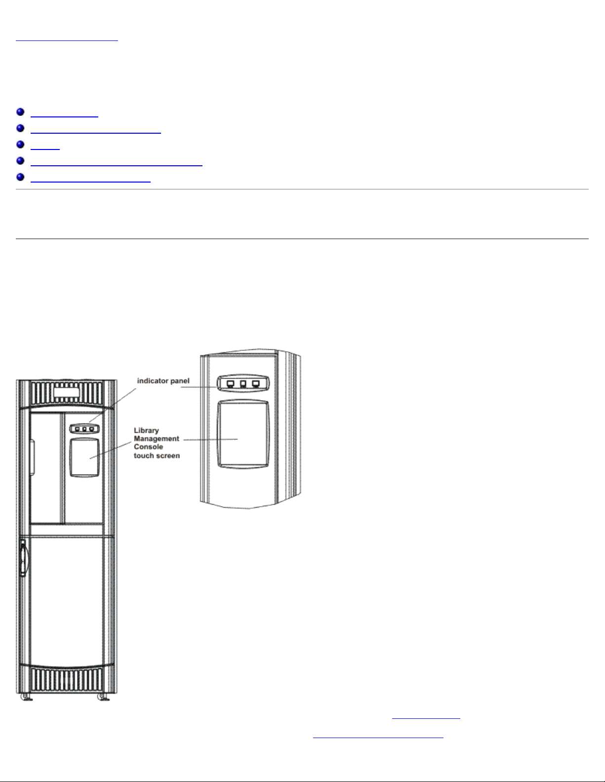
Operator Panel
The operator panel on the library includes an indicator panel and a touch screen. The indicator panel consists of a Robotics
Enabled button with its associated indicator, a Status indicator, and a Power button with its associated indicator. The
Library Management Console is displayed on the touch screen.
Figure 1. Operator Panel
For an explanation of functions associated with the buttons and indicators, refer to Indicator Panel.
For a brief overview of the Library Management Console, refer to Library Management Console
file:///C|/Users/greshma_dhanarajan/Desktop/ug/interfac.htm[5/16/2013 10:08:16 AM]
.
Page 19

Understanding the User Interface: Dell PowerVault 160T Tape Library User's Guide
Indicator Panel
The Robotics Enabled indicator and the Power indicator each contain a button. The Status indicator is not a button. These
indicators do not report the status of communications with a host.
Figure 2. Indicator Panel
Table 1. Robotics Enabled Indicator
Indicator Operational Status Operator Attention
Green/Steady The robotics are enabled to process or are
actively processing commands from the
library controller.
Do not open the front door.
Green/Blinking A state change is pending, either from
Enabled to Not Enabled or from Not
Enabled to Enabled.
Do not open the front door.
Off The robotics are not ready.
The doors may be opened.
NOTE: Enabled does not mean "communicating with the host." It means that the robot is communicating with the
library controller.
Table 2. Status Indicator
Indicator Operational
Status
Green/Steady Normal No attention required.
Amber/Blinking Fault Go to Tools—> Service. Attention required.
Off No Power Attention required. Power must be on to operate the library. Press the Power
Operator Attention
button.
No attention required.
No attention required.
Attention required. The operator should close the doors
and press the Robotics Enabled button to return to the
Enabled state.
Table 3. Power Indicator
Indicator Operational Status Operator Attention
Green/On Power on No attention required.
Off Power off Attention required. Power must be on to operate the library. Press the Power button.
Library Management Console (LMC)
The Library Management Console (LMC) can be viewed either on the touch screen or from a remote computer. If you are
using the touch screen, you do not need to install the Library Management Console because it is pre-installed. To install the
file:///C|/Users/greshma_dhanarajan/Desktop/ug/interfac.htm[5/16/2013 10:08:16 AM]
Page 20
Understanding the User Interface: Dell PowerVault 160T Tape Library User's Guide
Library Management Console on a remote system, refer to Installing the Remote Client.
NOTE: You cannot manage your library from the remote console until you have logged on to the LMC that runs on the
touch screen, and completed Running the
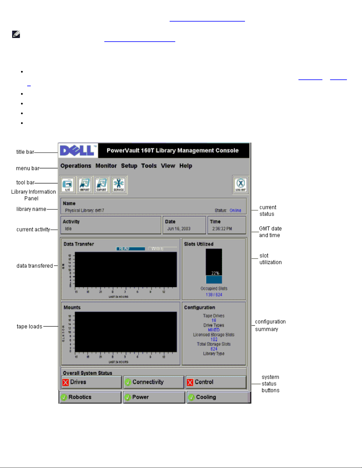
The LMC consists of five areas used to direct library activities: a title bar, a menu bar, a toolbar, the library information
panel, and the system status buttons.
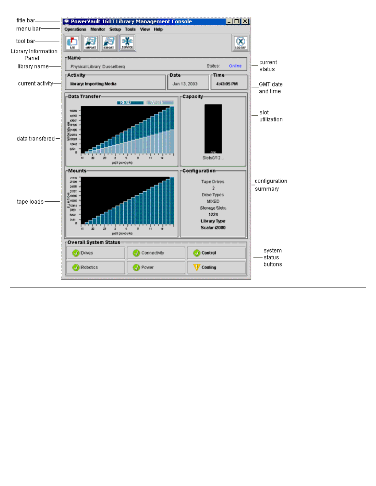
The title bar on the touch screen consists of the Dell logo and the words, Dell PowerVault 160T Tape Library
Management Console. The title bar as viewed from the remote console is a little different. Compare Figure 3
4. The remote console is easier to use for screens that require text entry.
The menu bar provides access to all the commands used to manage library functions.
The toolbar displays the most commonly executed commands.
The library information panel takes up most of the display to present operational data from the current library.
System status buttons provide current information for the six subsystems of the physical library.
Figure 3. Library Management Console (Local Touch Screen)
Setup Wizard from there.
to Figure
Figure 4. Library Management Console (Remote Console)
file:///C|/Users/greshma_dhanarajan/Desktop/ug/interfac.htm[5/16/2013 10:08:16 AM]
Page 21
Understanding the User Interface: Dell PowerVault 160T Tape Library User's Guide
Menus
LMC menus organize user commands into six groups: Operations, Monitor, Setup, Tools, View, and Help.
Use the Operations menu for day-to-day operations, including: changing mode, importing and exporting cartridges, taking
inventory, moving media; loading and unloading drives, and logging off.
Use the Monitor menu to view statistics at a glance as well as to get a detailed look at subsystem states. The choices
include: system, drives, connectivity, I/E station, slot, and media.
Use the Setup menu to configure the library. This tool provides configuration assistance for the following parameters:
partitions, device, connectivity, network configuration, physical library, users, notification, date and time, licenses, and e-mail
configuration.
Use the Tools menu to access diagnostic and maintenance tools for the physical library.They include: service, connectivity,
capture snapshot, and update software.
Use the View menu to specify the library-either physical or logical-information currently displayed in the Library Information
panel.
Use the Help menu to access online help as well as to learn the software build number and copyright date.
Some operations pertain only to a physical library, some only to a partition, and others can be carried out on either entity.
Table 4
you to take the library offline or to select the physical library if the command you are requesting requires you to change mode
file:///C|/Users/greshma_dhanarajan/Desktop/ug/interfac.htm[5/16/2013 10:08:16 AM]
summarizes all available commands by required user privilege level and required library environment. LMC prompts
Page 22

Understanding the User Interface: Dell PowerVault 160T Tape Library User's Guide
or window.
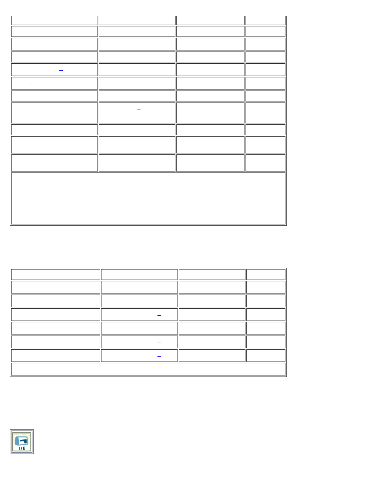
Table 4. Menu Commands: Privileges and Environments
Menu Command Privilege Level Physical Library Partition
Operations Menu
Change Mode Admin X
Import
Export
Drives
Load
Unload
2
2
2
2
2
Move Media
Inventory
3
2
Admin, User X X
Admin, User X X
Admin, User
X
X
Admin, User X
Admin
X
3
X
X
Logoff Admin, User, Guest X X
Monitor Menu
System Admin, User X X
Drives Admin, User X X
Connectivity Admin, User X X
I/E station Admin, User X X
1
2
Slot Admin, User X X
Media Admin, User
X X
Setup Menu
Setup Wizard Admin X
Partitions
4
Admin X
Device Admin X X
IDs
2
Admin X
FC Host Admin X
SCSI Host Admin X
Connectivity
4
Admin X
Network Configuration Admin X
Physical Library Admin X
Users Admin X
Notification Admin X
Date and Time Admin X
Licenses Admin X
file:///C|/Users/greshma_dhanarajan/Desktop/ug/interfac.htm[5/16/2013 10:08:16 AM]
Page 23
Understanding the User Interface: Dell PowerVault 160T Tape Library User's Guide
Tools Menu
Service Admin X
Drives
4
Admin X
Capture Snapshot Admin X
Update Software
4
Teach
4
Admin X
Admin
View
[system name]
Admin, User,
5
Guest
1
Help
Help Admin, User,
X X
Guest
About Admin, User,
X X
Guest
1
Users can make changes to or operate only those partitions to which they have privileges.
2
Relevant partition must be offline and the physical library must be online.
3Physical library must be online.
4
Physical library must be offline.
5Guest can read status off the display but cannot click the relevant status button for more
detail.
The system status buttons are displayed at the bottom of the library information panel. If the touch screen goes unused for a
period of time, the system status buttons operate as a screen saver. Users can see all states of the button statuses, but only
administrators can pull up tickets associated with buttons in a degraded or failed state.
Table 5. System Status Buttons
System Status Button Privilege Level Physical Library Partition
Drives
Connectivity
Control
Robotics
Power
Cooling
1
Guest can read status off the display but cannot click the relevant status button for more detail.
Admin, User, Guest
Admin, User, Guest
Admin, User, Guest
Admin, User, Guest
Admin, User, Guest
Admin, User, Guest
1
1
1
1
1
1
X X
X X
X X
X X
X X
X X
Toolbar
The toolbar contains icons that represent commonly used commands also available on the menus.
Figure 5. I/E Toolbar Button
file:///C|/Users/greshma_dhanarajan/Desktop/ug/interfac.htm[5/16/2013 10:08:16 AM]
Page 24

Understanding the User Interface: Dell PowerVault 160T Tape Library User's Guide
I/E displays a table of the current contents of the I/E station. The information displayed by this button can also be displayed
by selecting Monitor—> I/E Station. For an interpretation of the display, refer to Monitoring I/E Station Status
Figure 6. Import Toolbar Button
Import launches the import of cartridges, if the current library is a partition. An import can also be requested by selecting
Operations—> Import. For information about this command, refer to Importing Cartridges into Partitions
Figure 7. Export Toolbar Button
Export launches the export of cartridges, if the current library is a partition. An export can also be requested by selecting
Operations—> Export. For information about this command, refer to Exporting Cartridges from Partitions
Figure 8. Service Toolbar Button
.
.
.
Service launches the Service Wizard. This wizard can also be launched by selecting Tools—> Service. For information about
this command, refer to Troubleshooting
Figure 9. Log Off Toolbar Button
Log Off logs off the current user, after confirming the logoff request. Another way you can log off is to select Operations—>
Logoff. For information about this command, refer to Logging off
.
.
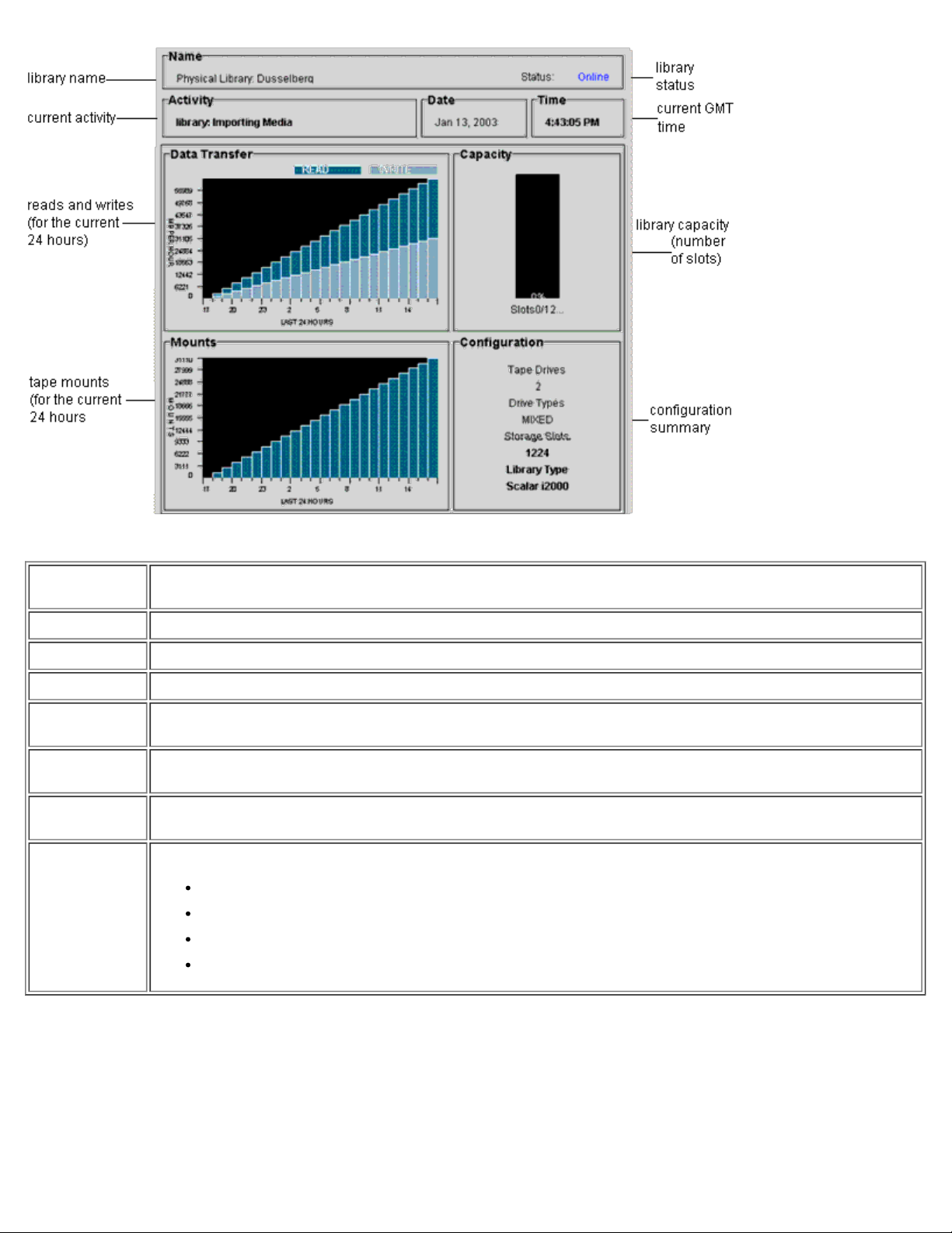
Reading the Library Information Panel
The library information panel occupies the central portion of the LMC display. It provides you with a great deal of status
information at a single glance. The following information is dynamically displayed:
Figure 10. Library Information Panel
file:///C|/Users/greshma_dhanarajan/Desktop/ug/interfac.htm[5/16/2013 10:08:16 AM]
Page 25
Understanding the User Interface: Dell PowerVault 160T Tape Library User's Guide
Table 6. Library Information Panel Data
Name The name of the current library. This is the library that appears with a checkmark beside it in the View
menu. The type of library is displayed first—physical or partition—followed by the name of the library.
Activity The current activity for the current library.
Date The current GMT date.
Time The current GMT time.
Data
Transfer
Capacity This graph displays the percentage of used media slots. The number of used media slots appears beneath
Mounts The bar graph reports mount statistics for the past 24 hours. This information is updated every five
Configuration Data points include:
The bar graph compares the amount of data read and written for the past 24 hours. The units being
reported will be displayed beside the graph.
the graph.
minutes.
Number of tape drives
Drive types: For example, LTO
Total number of storage slots
Library type (Dell PowerVault 160T)
System Status Buttons
Each of the six system status buttons includes an icon representing operational status of the library's subsystems. They are
located at the bottom of the Library Management Console display.
Figure 11. System Status Buttons
file:///C|/Users/greshma_dhanarajan/Desktop/ug/interfac.htm[5/16/2013 10:08:16 AM]
Page 26

Understanding the User Interface: Dell PowerVault 160T Tape Library User's Guide
If any button shows a degraded or failed state, all information reported is for the physical library only. Select the button to
view additional details. For more information on the status buttons, refer to the Interpreting the System Status Buttons
description that follows.
System Status at a Glance
There are three ways to obtain information about the system subcomponents:
Interpreting the System Status Buttons
Reading the Library Information Panel
Monitoring Library Subsystems
Interpreting the System Status Buttons
The overall system status panel is located below the library information panel. Each button represents one of the major
subsystems of the physical library. Subsystem status is reported on the face of the button as Good, Degraded, or Failed.
Figure 12. Reported Statuses
To get more information about a reported status, select the appropriate button for a specific subsystem.
If the state is Good, select the button to view a full status report for all relevant subcomponents.
If the state is Degraded or Failed, select the button to view a Current Problems dialog box that lists components of
the subsystem that are currently in a degraded or failed state. Follow the discussion in Displaying Service Tickets
Table 7
Control, Cooling, and Robotics subsystems all return the System Status dialog box, which contains information about
them. The Drives and Connectivity subsystems return dialog boxes specific to those subsystems. Partitions return only a
subset of this information.
Table 7. Information About the Physical Library Obtained From the Status Buttons
shows the information available for each subsystem of a physical library reporting a state of Good. The System,
Subsystem General Component
Information
Detailed Information
.
System Control Cooling
Power
System Name [System ID] [System Status]
Media Moves [Robot number] [Number of media moves within the history of the
Recovered Gets [Robot number] [Number of recovered gets within the history of the
Recovered Puts [Robot number] [Number of recovered puts within the history of the
file:///C|/Users/greshma_dhanarajan/Desktop/ug/interfac.htm[5/16/2013 10:08:16 AM]
library]
library]
library]
Page 27

Understanding the User Interface: Dell PowerVault 160T Tape Library User's Guide
Recovered Scans [Robot number] [Number of recovered scans within the history of the
library]
MCB Status [ID number] Good, Degraded Failed
RCU Status [ID number] Good, Degraded Failed
Vertical Motion N/A [Meters traveled within the history of the library]
Horizontal Motion N/A [Meters traveled within the history of the library]
Drives
Drive ID Drive type
World Wide Name (WWN)
Firmware revision
Loaded, loading, unloaded or empty
Location of the drive
Serial number
Number of loads
Vendor
Write protected
Compression on or off
Power on or off
Date and time of error
Error message for each drive listed
Connectivity N/A
Back to Contents Page
file:///C|/Users/greshma_dhanarajan/Desktop/ug/interfac.htm[5/16/2013 10:08:16 AM]
Page 28

Working With Cartridges and Barcodes: Dell PowerVault 160T Tape Library User's Guide
Back to Contents Page
Working With Cartridges and Barcodes: Dell™
PowerVault™ 160T Tape Library User's Guide
Cartridge Handling Practice
Write-Protecting Cartridges
Installing Barcode Labels
Using Cleaning Cartridges
Managing Media
The Library Management Console unifies and simplifies cartridge loading and unloading, importing and exporting, moving and
inventory. The library expands to 1344 LTO media slots, and can accommodate Fibre LTO-1 or Fibre LTO-2 cartridges. Every
partition in the library must contain at least one cleaning cartridge.
Cartridge Handling Practice
To ensure the longest possible life for all of your cartridges, follow these guidelines:
Select a visible location to post procedures that describe proper media handling.
Ensure that anyone who handles cartridges has been properly trained in all procedures.
Do not drop or strike a cartridge. Excessive shock can damage the internal contents of the cartridge or the cartridge
case itself, making that cartridge unusable.
Do not expose cartridges to direct sunlight or sources of heat, including portable heaters and heating ducts.
Do not stack cartridges more than five high.
The operating temperature range for LTO cartridges is 10º to 35ºC. The storage temperature range is 16º to 32ºC in a
dust-free environment with a relative humidity range between 20% and 80% (non-condensing).
If a cartridge has been exposed to temperatures outside the ranges specified above, stabilize the cartridge at room
temperature for the same amount of time it was exposed to extreme temperatures or 24 hours, whichever is less.
Do not place cartridges near sources of electromagnetic energy or strong magnetic fields, such as computer monitors,
electric motors, speakers, or x-ray equipment. Exposure to electromagnetic energy or magnetic fields can destroy data
and the embedded servo code written on the media by the cartridge manufacturer, rendering the cartridge unusable.
Place identification labels only in the designated slot on the cartridge.
If you ship a cartridge, ship it in its original packing or something stronger than that.
Do not insert a damaged cartridge into a drive.
Do not touch the tape or tape leader.
Do not degauss a cartridge that you intend to reuse.
Write-Protecting Cartridges
All cartridges have a write-protect switch to prevent accidental erasure or overwriting of data. Before loading a cartridge into
the library, make sure the write-protect switch on the front of the cartridge is positioned correctly. Slide the switch to the
right to write-protect the cartridge.
For LTO cartridges, a small, orange padlock is visible when the cartridge is write-protected. See Figure 1 for the
location of the switch.
Slide the switch to the left to allow the library to write to the tape.
The write-protect switch displays a black void when the cartridge permits overwriting and erasure.
Figure 1. Write-Protect Switch on an LTO-1 Cartridge
file:///C|/Users/greshma_dhanarajan/Desktop/ug/tapes.htm[5/16/2013 10:08:17 AM]
Page 29

Working With Cartridges and Barcodes: Dell PowerVault 160T Tape Library User's Guide
Installing Barcode Labels
You must apply all barcode labels to the front of the cartridge. Depending on the media type, barcode labels are either
stickers that are adhered to the front of the tape cartridge or cutouts that you slide into an indentation on the front of the
cartridge.
Peel off the label and place it on the cartridge. Verify that label is oriented so the numbers appear right-side up and above
the barcode.
Figure 2. Applying the Barcode Label
NOTICE: Be careful not to apply barcode labels upside down.
Using Cleaning Cartridges
Most tape drives require occasional cleaning. A cleaning cartridge cleans accumulated debris from the tape drive and the
read/write head.
NOTICE: You must use a separate cleaning cartridge for each partition in the library.
Backup applications or archive software applications use different techniques to automate the process of cleaning drives.
These tools specify cleaning cycles based on cycle counts of the drive, drive requests, or at a regularly scheduled interval.
The cleaning process itself requires certain considerations:
Cleaning tapes must be labeled with a barcode. In some cases, specific labels have been established as industry
file:///C|/Users/greshma_dhanarajan/Desktop/ug/tapes.htm[5/16/2013 10:08:17 AM]
Page 30

Working With Cartridges and Barcodes: Dell PowerVault 160T Tape Library User's Guide
standard. For instance, the prefix "CLN" might be used to identify a cleaning tape. The library does not require a
specific content to the label and accepts conventional tape labels.
Insert a cleaning tape just as you do any other data tape. For example, the most common method is by means of the
I/E station using host application control.
Cleaning tapes often have limited lives that can be as few as 20 cycles. The controlling host application manages the
number of uses of a cleaning tape. Errors can occur if a tape is inserted into a drive when the tape has already been
used the maximum number of times.
Export a cleaning tape just as any other data tape.
The concept of physical and logical libraries must be considered when setting up cleaning procedures and methods. In
general, cleaning cartridges must be treated in the same manner as data cartridges. Any physical cartridge, cleaning or
data, can only exist in one logical library. There can be no sharing of cleaning cartridges between logical libraries.
Managing Media
The Library Management Console provides you with interfaces for:
Importing and exporting cartridges
Moving media from one storage location to another
Loading and unloading drives
Taking inventory
The following sections provide step-by-step instructions for performing these tasks.
Importing Cartridges into Partitions
When you first start using your library, open the door and manually insert as many cartridges as you plan to use directly into
storage slots. The cartridges will not go back all the way if they are inserted incorrectly.
After your library is in operation, use the Import command to add cartridges without interrupting library operations. Place
cartridges in the I/E station. The scanner automatically reads the barcodes on new cartridges.
1. Select a partition. To find out how to do so, refer to Selecting a Library or Partition
The system prompts you to take the partition offline, if it is not currently in that state.
2. Insert a data cartridge into an appropriate I/E station. You may insert multiple cartridges up to the maximum number
of slots in your I/E station.
NOTE: To see which I/E stations are associated with a particular partition, select Monitor—> I/E station.
3. Select Operations—> Import or use the Import toolbar button.
A table of cartridges in the I/E station is displayed.
The following information is displayed in the table:
Table 1. Information Displayed by Operations—> Import
.
Designation Description
Media ID Cartridge barcode.
Slot The location of the cartridge. For help understanding the location designation, refer to
Understanding Location Coordinates
I/E station The number of the module. For help understanding the location designation, refer to
Understanding Location Coordinates
Magazine The number of the magazine (section) where the slot is located, numbered from the top down.
For help understanding the location designation, refer to Understanding Location Coordinates
file:///C|/Users/greshma_dhanarajan/Desktop/ug/tapes.htm[5/16/2013 10:08:17 AM]
.
.
.
Page 31

Working With Cartridges and Barcodes: Dell PowerVault 160T Tape Library User's Guide
Results "Imported" or "Failed".
4. Select Import.
The picker moves the cartridge automatically from the I/E station to the first available empty slot in that
partition. You cannot manually specify the slot.
Exporting Cartridges from Partitions
Use the Export command to take cartridges out of the partition.
1. Select a partition. To find out how to do so, refer to Selecting a Library or Partition
2. Select Operations—> Export or use the Export toolbar button.
The system prompts you to take the partition offline, if it is not currently in that state.
A table of cartridges in the partition is displayed.
3. Select entries in the table to designate the cartridges for export.
The maximum number of cartridges available for export is displayed at the top of the table.
4. Select OK to continue.
All the designated cartridges are exported into I/E station slots selected automatically by the system. Items in
the table are dynamically refreshed when the operation is complete.
Loading Drives
Use the Drives command to load drives with cartridges from the current partition.
1. Select a partition. To find out how, refer to Selecting a Library or Partition
2. Select Operations—> Drives—> Load.
A media table and a drive table are displayed in the dialog box.
3. Enter a media filter, if appropriate, into the Media ID text box.
.
.
The media filter performs a search for media IDs that match a particular pattern. For example, the media filter
can be set to capture media IDs beginning with the string "J00" by entering "J00*" (without the quotes).
4. Select the data cartridge to load into the drive.
NOTE: You can load only one cartridge at a time.
The parameters used to define a cartridge are media ID (barcode) and location. Location is defined as a series of
coordinates representing the aisle, module, rack, section, column, and row where a cartridge is located. Refer to
Understanding Location Coordinates
The upper portion of the table, labeled Select Media shows the full slots.
5. Select the destination drive to receive the media. The lower portion of the table, labeled Select Drive is populated
with empty drives.
You can select only one drive at a time.
6. Select OK to load the data cartridge into the selected drive.
.
Unloading Drives
Use the Unload command to rewind the cartridge in the drive, eject it, and return it to storage.
NOTE: Select a partition before you start unloading drives.
file:///C|/Users/greshma_dhanarajan/Desktop/ug/tapes.htm[5/16/2013 10:08:17 AM]
Page 32

Working With Cartridges and Barcodes: Dell PowerVault 160T Tape Library User's Guide
1. Select Operations—> Drives—> Unload.
A table of media is displayed in the Unload Drives dialog box.
2. Select the drive you want to unload. You can only unload one drive at a time.
Use the media filter to perform a search for media IDs that match or contain a particular pattern.
The parameters used to define a cartridge are media ID (barcode) and location. Location is defined as a series of
coordinates representing the aisle, module, rack, section, column, and row where a cartridge is located. Refer to
Understanding Location Coordinates
3. Select OK to rewind the data cartridge, unload it from the drive, and return it to storage.
.
Moving Media
The Move Media command allows you to move media from one location to another within a partition.
NOTE: Only one cartridge can be moved at a time.
1. Select a partition. To find out how, refer to Selecting a Library or Partition.
2. Select Operations—> Move Media.
The Move Media dialog box is displayed. It consists of two tables, the Select Source table and the Select
Target table.
When the dialog box first appears, the Select Source table is filled with full slots and the Select Target table is
filled with empty slots.
You can filter the information in the Select Source table so that only a particular cartridge or a cartridge
subgroup within a specified sublocation is displayed. Do the following as necessary:
a. Type the barcode associated with a particular cartridge into the Media ID text box. Or use the media filter
to perform a search for media IDs that match or contain a particular pattern. Select Filter.
b. Select the arrow next to the location coordinate boxes across the top of the Select Source dialog box.
Then select an appropriate number. Then select Show.
3. In the Select Source table, select the media ID for the cartridge that you want to move. You may need to scroll down
to see media IDs for cartridges that are in drives or I/E stations.
4. In the Select Target table, select the destination for the media. You may need to scroll down to find appropriate drive
or I/E station locations. You can limit the selection by using the sublocations listed in the Drive Type pull down: i/e
station, storage, or drive.
5. To complete the operation, select OK.
To close the dialog box without moving any media, select Cancel.
Inventory
The Inventory command causes the library to scan all storage locations, drives, and I/E stations. Inventory is completed
automatically whenever the doors are shut. Inventories can be configured to occur whenever power is turned off and on, or
by using the Inventory command. To enable automatic inventories, refer to Setting up Policies for the Physical Library
.
1. Log on as Administrator.
2. Select Operations—> Inventory.
The Inventory dialog box is displayed.
3. Click OK.
Back to Contents Page
file:///C|/Users/greshma_dhanarajan/Desktop/ug/tapes.htm[5/16/2013 10:08:17 AM]
Page 33

Configuring the Library: Dell PowerVault 160T Tape Library User's Guide
Back to Contents Page
Configuring the Library: Dell™ PowerVault™ 160T Tape
Library User's Guide
After Completing the Setup Wizard Setting up Notification
Selecting a Library or a Partition Specifying the Date and Time
Working With Partitions Enabling Licenses
Selecting a Mode Configuring Devices
Setting up Network Configuration FC Host
Managing Connectivity SCSI Host
Setting up Policies for the Physical Library Configuring E-mail Settings
The library allows you to configure policies, e-mail, and notification mechanisms. It also allows you to configure drive, host,
and media access in a partitioned environment. License keys can be upgraded at any time to provide increased storage or
partition needs.
After Completing the Setup Wizard
1. Read this guide to familiarize yourself with all menus and tools from the Library Management Console.
NOTICE: If you have configured more than one partition, use the I/E station to import cartridges.
2. Make decisions based on your configuration.
3. If your host(s) are connected through the management control blade run FC Host or SCSI Host, as appropriate, to
allow the library to manage your media. Refer to FC Host
4. If your host(s) are directly connected to drives, configure your third-party tape handling software.
5. Set up other users and grant them appropriate privileges. For instructions, refer to Creating User Accounts
6. Follow the instructions in Configuring E-mail Settings
NOTE: If you configured the e-mail settings in the course of installing a remote client, you do not need to
configure them again.
7. Set up notifications. For instructions, refer to Setting up Notification.
8. Install (and launch) a remote client so you can use all library features. For instructions, refer to Installing a Remote
Client.
Updating software requires a remote client connection.
Saving or printing reports requires a remote client connection.
or SCSI Host.
.
.
Selecting a Library or Partition
1. Select the View menu.
2. Select the name of the library or partition to view statistics or to operate.
The physical library is listed above the dividing line
Partitions are listed below the dividing line
Information about the selected library is displayed in the library information panel.
file:///C|/Users/greshma_dhanarajan/Desktop/ug/config.htm[5/16/2013 10:08:18 AM]
Page 34

Configuring the Library: Dell PowerVault 160T Tape Library User's Guide
Working with Partitions
A partition is an abstraction of a single underlying physical library that presents the appearance of multiple, separate libraries
for purposes of file management, access by multiple users, or dedication to a specific host application. You can choose to run
one software application in one partition, for example, and a different software application in a second partition. Partitions are
also known as logical libraries.
Each partition contains the following components of the physical library:
Medium changer—the robotic assembly that shuttles removable media throughout the system. Also known as the
media transport element.
I/E station—a magazine containing slots that allow removable media to be introduced into or removed from the
physical library. The type of media determines the number of slots. For example, in an LTO magazine there are six
slots.
Storage segment—a static column location within a section of the physical library rack that holds removable media. For
more about location coordinates, refer to Understanding Location Coordinates
Drive segment—the read/write device for removable media. Also called the data transport element.
A partition consists of, at minimum, one storage segment and one drive. Neither the storage segment nor the drive can be
shared with another partition. Each partition is specific to a media type (for example, LTO-1, LTO-2) and a drive interface (for
example, Fibre). The magazines in an I/E station can be shared by up to four partitions. Only components belonging to the
same media class can be assigned to a partition. The maximum number of partitions is limited to the lesser of the number of
drives available in the physical library (assuming there are at least as many storage slots), or 16.
.
Configuration controls such as FC Host and SCSI Host provide the means to permit host access to a particular partition.
Multiple hosts can share a single partition or a partition can be restricted to one exclusive host.
The host applications control access to elements within the shared partition. When the hosts are connected directly to the
drives, this is true exclusively. When the hosts connect through the MCB or an I/O blade, the library also has access to
partition elements, such as drives, media, etc. Multiple applications may each have a partition assigned to them. Each
application uses its partition as if it were a dedicated physical library.
Creating Partitions
1. Log on as Administrator.
2. If you are not already working from the physical library, select it from the View menu. Refer to Selecting a Library or
Partition.
3. Select Setup—> Partitions.
NOTE: Be sure that you have adequately planned for the number of partitions that you want to configure.
The Partitions dialog box is displayed.
Your library comes with one partition already configured. You must delete the existing partition before you can
create others.
NOTICE: Whenever an existing partition is deleted, extreme care must be taken to recreate a partition
that includes the same media type, interface, I/E station magazines, and a host at the same LUN, for the
host application to have access to previously written data.
4. Select the existing partition, and then select Delete.
If the partition is online, you will be asked whether or not it can be taken offline.You must answer Yes to
continue the deletion process.
The selected partition is deleted and the Partitions dialog box is refreshed. The Create button becomes
available.
5. Select Create. The Choose Creation Mode dialog box is displayed.
6. Select either Automatic or Manual.
Automatic partitions are created according to the following system defaults:
file:///C|/Users/greshma_dhanarajan/Desktop/ug/config.htm[5/16/2013 10:08:18 AM]
Page 35

Configuring the Library: Dell PowerVault 160T Tape Library User's Guide
Media type checking is enabled
The slots for the specified media type are equally divided among the number of libraries that you have specified
for a particular media type.
If you select Automatic, the Automatic Creation dialog box is displayed. Proceed to Creating Partitions Using
Automatic Mode.
If you select Manual, the Choose Partition Properties dialog box is displayed. Proceed to Creating Partitions
Using Manual Mode.
Creating Partitions using Automatic Mode
1. After completing the steps in Creating Partitions, enter the number of partitions to create in the column labeled
Partitions.
The maximum number of partitions that you can enter is determined by the number of partitions you are
licensed to create. Partitioning licenses are available for either one partition or 16 partitions. Refer to Enabling
Licenses.
Typically, each partition should have at least one dedicated drive. For more information about partitions, refer to
Working with Partitions
2. Select Finish to create the libraries and exit the automatic partition creation process.
.
Creating Partitions Using Manual Mode
1. After completing the steps in Creating Partitions, enter defining parameters into the Choose Partition Properties
dialog box for the library you are creating.
Type a name into the Name box.
Select a media type from the Media Type drop-down box.
NOTE: The product ID is Scalar i2000.
2. Select Next to proceed.
The Choose Policy Settings dialog box is displayed.
3. Media type checking is enabled by default. When cartridges are imported or mounted, the system automatically checks
the media type.
If you do not want the media type to be checked automatically when cartridges are inserted into the library,
select Disable.
If you want the media type to be checked automatically when cartridges are inserted into the library, leave the
selection at Enable.
4. Select Next to proceed.
The Choose Resource Quantities dialog box is displayed.
5. Enter the number of elements to include in the partition by specifying three parameters:
Number of drives
Number of storage slots
Number of I/E magazines
6. Select Next.
The Summary Information dialog box is displayed.
7. To create the partition, select Create.
The Partitions - Completed dialog box is displayed.
8. Review the information to make certain it is correct.
file:///C|/Users/greshma_dhanarajan/Desktop/ug/config.htm[5/16/2013 10:08:18 AM]
Page 36

Configuring the Library: Dell PowerVault 160T Tape Library User's Guide
The partition license on the library is initially configured to allow two partitions. To create a second partition,
repeat the steps of the procedure Creating Partitions Using Automatic Mode
Choose Resource Quantities dialog box displays. This time it looks a little different.
The system has adjusted the number of drives, storage slots, and I/E magazines available based on your
previous partition.
. After you complete Step 4, the
Deleting Partitions
NOTICE: Whenever an existing partition is deleted, extreme care must be taken to recreate a partition that includes
the same media type, interface, I/E station magazines, and a host at the same LUN, for the host application to have
access to previously written data.
1. Log on as Administrator.
2. If you are not already working from the physical library, select it from the View menu. Refer to Selecting a Library or
Partition.
3. Select Setup—> Partitions.
The Partitions dialog box is displayed.
4. Select the name of the partition you want to delete.
NOTE: Only one partition can be deleted at a time.
5. Select Delete.
a. If the partition is online, you will be asked whether or not it can be taken offline.You must answer Yes to
continue the deletion process. If you answer Yes, the partition is taken offline.
b. Select Delete.
The selected partition has been deleted. Repeat the process to delete another partition, or select Close.
Selecting a Mode
When you issue a command that requires the library to undergo a change in its operational status, you are always asked to
confirm the change first. To find out which commands require the library to be taken offline, refer to Table 4
1. Select Operations—> Change Mode.
The Change Library Mode dialog box is displayed.
2. Do one of the following:
Selecting Online sets the library within the current view to the normal operating condition. In this mode the
robotics are enabled and all host commands are processed.
Selecting Offline allows you to take the current library to an offline state. Host commands are not processed. If
the library is a physical library with partitions, all partitions are also taken offline. If the library is a partition,
other partitions are not affected.
Selecting Shutdown allows the operator to properly shut down the library. All active commands from the host
are completed, but no new commands are accepted. This option is available only when a physical library has
been selected and you are working from the touch screen. All associated partitions are also shut down. After the
front panel goes dark, push the Power button to turn the library off. For the location of the Power button, refer
to Indicator Panel
.
.
Setting up Network Configuration
NOTE: You can configure the network only from the touch screen.
file:///C|/Users/greshma_dhanarajan/Desktop/ug/config.htm[5/16/2013 10:08:18 AM]
Page 37

Configuring the Library: Dell PowerVault 160T Tape Library User's Guide
Make certain that your library is attached to the network before you use the Network Configuration command. You must
fully understand all network issues before you change the network configuration for a working system:
1. Log on as Administrator.
2. Select the physical library. To find out how to select a particular library, refer to Selecting a Library or Partition.
3. Select Setup—> Network Configuration.
The Network Configuration dialog box is displayed.
4. Make entries or changes in the text boxes, as appropriate:
If you have DHCP enabled on your network, select Enable and enter the DHCP server name in the Library
Name box.
If you do not have DHCP enabled on your network, select Disable and enter the IP Address of the library in the
IP Address box.
Enter the subnet mask and the IP address of the default gateway for your portion of the Ethernet network in the
Subnet Mask and Default Gateway boxes, respectively.
If necessary, consult with your network administrator to verify this information.
5. Select OK.
NOTE: After you change the network configuration, the touch screen display is automatically restarted. It will take a
few minutes for the LMC to be restored to the touch screen.
Managing Connectivity
The Connectivity command on the Setup menu allows you to configure parameters for FC (Fibre Channel) connectivity. You
can view the settings for SCSI connectivity.
1. Log on as Administrator.
2. Select the physical library. To find out how to select a particular library, refer to Selecting a Library or Partition
3. Select Connectivity—> Setup.
The Connectivity dialog box is displayed.
4. Select a SCSI channel or a Fibre Channel, and then select Configure.
If you select a SCSI channel, the SCSI Channel Parameters dialog box is displayed. If you select a Fibre
Channel, the Fibre Channel Parameters dialog box is displayed. You cannot configure settings on the SCSI
Channel Parameters dialog box.
5. On the Fibre Channel Parameters dialog box, you can configure two settings for the MCB connection and all settings
for I/O blade connections. Selecting Soft acts as a toggle, checking and clearing the box. If the box is unchecked, you
can select a hard loop ID from the drop down list by specifying a number within the range of 0 to 125. Some operating
systems require hard ID settings. Consult your service representative before making changes to this setting.
6. The default connection option mode is Loop. Other options include Loop Preferred, Point to Point, and Point to
Point Preferred. Consult your service representative before making changes to this setting.
7. When you have made configuration choices, click OK.
You are prompted to reset the channel. If you select Yes, the channel resets immediately. If you select No, you
must reset the channel manually, using the Reset button at the bottom of the dialog box before exiting the
procedure.
.
If you do not reset the channel, the next time you open the Fibre Channel Parameters dialog box, your
pending changes will be displayed in a sidebar.
Setting up Policies for the Physical Library
The Physical Library command allows you to configure various operating modes, including:
file:///C|/Users/greshma_dhanarajan/Desktop/ug/config.htm[5/16/2013 10:08:18 AM]
Page 38

Configuring the Library: Dell PowerVault 160T Tape Library User's Guide
Enable or disable Automatic Teach
Specify whether or not the robotic assembly should be automatically calibrated and configured, if necessary, each time
the power cycles off and on.
Enable or disable Automatic Inventory
Specify whether or not the library should scan inventory automatically each time the power cycles off and on.
1. Log on as Administrator.
2. Select the physical library. To find out how to select a particular library, refer to Selecting a Library or Partition
3. Select Setup—> Physical Library.
The Physical Library dialog box is displayed.
4. Select Enable in the Automatic Teach area to schedule automatic calibration and configuration of the robotic
assembly upon power up.
Automatic Teach is disabled by default.
5. Select Enable in the Automatic Inventory area to schedule automatic inventories of library contents upon power-up.
Automatic Inventory is disabled by default.
6. When you have finished configuring the parameters, select OK.
.
Setting up Notification
The Notification command allows you to send e-mail to specific individuals whenever certain conditions occur.
1. Log on as Administrator.
2. If you are not already working from the physical library, select it from the View menu. Refer to Selecting a Library or
Partition.
3. If you have not already configured an e-mail server, complete the steps in Configuring E-mail Settings
proceeding.
4. Select Setup—> Notification.
The Notification dialog box is displayed.
The default notification address for Severity 1 issues is support@us.dell.com.
5. To delete an e-mail address, select the address in this dialog box, and then select Delete.
6. Select Create to enter an e-mail address. The New Email Notification dialog box is displayed.
7. Type in the e-mail address in the blank box after the words Email Address.
Do not enter multiple addresses into this box. To associate more than one e-mail address with events of a particular
severity, repeat the Create process.
8. Select the severity level that will be reported.
The severity levels are numbered from 1 to 5, with 5 being the least severe. If you specify level 3, notifications are not
sent for events that are associated with levels 1, 2, 4, or 5. Level 5 represents a return to "Good" from "Degraded" or
"Failed."
before
Level Meaning
1 Failed
2 Degraded
3 Warning
4 Information
file:///C|/Users/greshma_dhanarajan/Desktop/ug/config.htm[5/16/2013 10:08:18 AM]
Page 39

Configuring the Library: Dell PowerVault 160T Tape Library User's Guide
5 Good
You can select multiple severity levels by holding down shift and clicking each choice.
Repeat Step 5 to Step 7 as often as necessary.
Select OK on the New Email Notification dialog box.
When your specifications have been completely entered, select OK on the Notification dialog box.
Specifying the Date and Time
The Date and Time command is used to set system time (if you are not using the Setup Wizard to configure your system)
or to reset system time.
1. Log on as Administrator.
2. If you are not already working from the physical library, select it from the View menu. Refer to Selecting a Library or
Partition.
3. Select Setup—> Date and Time. The Date and Time dialog box is displayed.
4. In the Date and Time dialog box, set the following parameters:
Use the pull-down menus to set the month, date, and year.
Use the pull-down menus to set the hour, minute, and-because the clock is not a 24 hour clock- whether the
time is am or pm.
NOTE: Use Greenwich Mean Time.
5. Select OK.
Enabling Licenses
The Licenses command is used to enable specific features:
Scalability
You can scale from 100 to 1344 LTO cartridges and up to 48 LTO drives by simply using a new software key. These
numbers vary by drive type.
Partitioning
The number of partitions is limited to the number of drives available in the physical library (assuming there are at least
as many storage slots), or 16.
1. Log on as Administrator.
2. If you are not already working from the physical library, select it from the View menu. Refer to Selecting a Library or
Partition.
3. Select Setup—> Licenses.
The Licenses dialog box is displayed.
Licensed features are shown with the status and expiration date for each feature.
4. Enter the appropriate license key into the text box after Enter License Key.
5. Select OK.
Configuring Devices
The Setup—> Device command allows you to change the way system components are mapped.
file:///C|/Users/greshma_dhanarajan/Desktop/ug/config.htm[5/16/2013 10:08:18 AM]
Page 40

Configuring the Library: Dell PowerVault 160T Tape Library User's Guide
The IDs command is available from the physical library. Use this to set the Loop ID of a drive. All hosts viewing the drive will
see the same Loop ID associated with the drive.
FC Host and SCSI Host are available from the partition. Use them to configure access to partitions on a per-host basis. If
you have connected your host to either the FC port or the SCSI port on the MCB, you must map the appropriate partitions
with either FC Host or SCSI Host. If you have connected your hosts directly to the drives, use the third-party software of
your choice to manage your media from the host itself.
If you have not otherwise restricted access, FC Host has full control of all LUNs on all FC and SCSI channels. Each FC host
can be configured to access a maximum of 255 LUNs, up to an overall system total of 2048.
If you have not otherwise restricted access, SCSI Host has full control of all LUNs on all FC and SCSI channels, up to an
overall system total of 2048. SCSI hosts can configure access at the LUN-level for an overall system total of up to 2048 LUNs.
Setting Device IDs
From a partition you can change the Loop ID for a Fibre-attached drive. For example, the default Loop ID for a drive that you
are installing may conflict with the assigned Loop ID of an existing drive. You may be using an application that expects to
communicate with a device at a specific Loop ID, but that ID may already have been configured for use in another partition.
Use the IDs command on the Device submenu to correct these situations.
1. Log on as Administrator.
2. If you are not already working from a partition, select it from the View menu. Refer to Selecting a Library or Partition
3. Select Setup—> Device—> IDs.
.
The Device IDs dialog box is displayed.
Figure 1. Device IDs Dialog Box
The drive shown in Figure 1 is in the topmost of the twelve drive bays in a control module. See Figure 2. To
better understand location coordinates, refer to Understanding Location Coordinates
.
Figure 2. Drive Position (1,1,1,12,1,1)
file:///C|/Users/greshma_dhanarajan/Desktop/ug/config.htm[5/16/2013 10:08:18 AM]
Page 41

Configuring the Library: Dell PowerVault 160T Tape Library User's Guide
4. To specify a particular ID for an FC drive, select a new FC ID number by using the arrow beside the New ID box. or
select the check box in front of Soft to automatically assign an FC ID.
5. Select Set.
FC Host
The FC Host feature allows an FC-attached host to create a virtual private remapping of available LUNs.
NOTE: Use FC Host to map partitions when a Fibre Channel host is connected to the MCB.
Depending upon host operating system constraints, it may be necessary to reboot or reconfigure a host as a result of device
map changes resulting from using FC Host.
1. Log on as Administrator.
2. If you are not already working from the physical library, select it from the View menu. Refer to Selecting a Library or
Partition.
3. Select Setup—> Device—> Access—> FC Host.
A dialog box is displayed. Long strings may not be visible at first, but the FC Host dialog box is sizeable.
NOTE: If you do not have an Fibre Channel host connected to the library, the FC Host command is not
available.
The host's port, blade, and WWN (World Wide Name) are displayed.
4. Select an FC host to configure.
5. With the host selected, select LUN Mapping.
The dialog box in Figure 3
the Show Details view displayed in Figure 5
serial number of the logical library are shown in the Device column. In the default view, only the names of
available partitions are shown in the Device column. LUN spaces from 0-255 are always available in the
LUN/Device column, no matter what view you have chosen.
is displayed. In Figure 3 you can see the default view. Compare the default view to
. In the Show Details view, the name, product ID, vendor ID, and
In Figure 3
heavy black type in the Device column. Partitions are treated by the system as devices. You must drag a
partition to the LUN/Device column for the Library Management Console to manage it and its media. In this
example, the control LUN has already been remapped as shown in heavy black type in the LUN/Device column.
file:///C|/Users/greshma_dhanarajan/Desktop/ug/config.htm[5/16/2013 10:08:18 AM]
, the partitions (devices) that have not yet been manually reassigned to a new map position appear in
Page 42

Configuring the Library: Dell PowerVault 160T Tape Library User's Guide
In Figure 4 all devices have been manually mapped. The new map locations appear in heavy black type in the
LUN/Device column. The previous (default) device map position of a remapped device is shown in gray type in
the Device column.
Figure 3. FC Host LUN Mapping Dialog Box (Default View)
6. Drag and drop the devices from the Device column to the appropriate LUN assignment in the LUN/Device column.
7. Select OK to save the mapping.
The FC Host map is automatically saved as part of the configuration.
Figure 4. FC Host Devices Mapped (Default View)
file:///C|/Users/greshma_dhanarajan/Desktop/ug/config.htm[5/16/2013 10:08:18 AM]
Page 43

Configuring the Library: Dell PowerVault 160T Tape Library User's Guide
Figure 5. FC Host LUN Mapping Dialog Box (Show Details View)
file:///C|/Users/greshma_dhanarajan/Desktop/ug/config.htm[5/16/2013 10:08:18 AM]
Page 44

Configuring the Library: Dell PowerVault 160T Tape Library User's Guide
When a device has been mapped, it is still listed, though unavailable, in the Device column.
In Figure 4 the LUNs are not currently available for mapping, because they have already been mapped into the
LUN/Device column. The device that was formerly found at assigned LUN 3 is now found at assigned LUN 1. Drag it
back into the Device column to make it available for re-mapping.
Setting the View for the FC Host Device Column
Select the View menu on the FC Host dialog box. If you want to see product details, select the box in front of Show
Details. If you want to see only the names of the devices available for mapping, select Show Details again to toggle
the display back to the default.
Modifying FC Host settings
FC hosts can be reconfigured without powering down the system.
1. With the host selected in the FC Host dialog box, select Modify.
The Host Configuration dialog box is displayed.
2. Change the Name, Type, or Port. You can not change the WWN.
3. Select the OK button to keep the changes you made.
SCSI Host
The Library Management Console SCSI Host feature allows a SCSI-attached host to create a virtual private remapping of
available LUNs.
file:///C|/Users/greshma_dhanarajan/Desktop/ug/config.htm[5/16/2013 10:08:18 AM]
Page 45

Configuring the Library: Dell PowerVault 160T Tape Library User's Guide
NOTE: Use SCSI Host to map partitions when a SCSI host is connected to the MCB.
Before you map devices using SCSI Host, you must configure system components appropriately.
1. Log on as Administrator.
2. If you are not already working from the physical library, select it from the View menu. Refer to Selecting a Library or
Partition.
3. Select Setup—> Device—> Access—> SCSI Host.
The SCSI Host dialog box is displayed.
4. Select a SCSI port to configure.
5. With the port selected, select LUN Mapping.
The SCSI Host Map dialog box is displayed.
Figure 6. SCSI Host Map Dialog Box (Default View)
6. Drag the partitions that you want the SCSI host to manage from the Device column to the ID/LUN/Device column.
In Figure 6
connection are shown. Compare this view to the Show Details view displayed in Figure 7
view, partition name, product ID, vendor ID, serial number, and the SCSI ID of the host connection are shown.
In Figure 8
ID/LUN/Device column. The previous (default) device map position of a mapped device is shown in gray type
in the Device column. In Figure 6
map position appears in heavy black type in the Device column. The control LUN and the "LTO1" partition have
been mapped in Figure 6
7. Drag and drop the devices from the Device column to the appropriate LUN assignment in the ID/LUN/Device
column.
file:///C|/Users/greshma_dhanarajan/Desktop/ug/config.htm[5/16/2013 10:08:18 AM]
you can see the default view. In the default view, only partition names and the SCSI ID of the host
. In the Show Details
all devices have been manually mapped. The new map locations appear in heavy black type in the
, the partition (device) that has not yet been manually reassigned to a new
.
Page 46

Configuring the Library: Dell PowerVault 160T Tape Library User's Guide
The right column of the SCSI host map dialog box, labeled Device, lists all available devices. The
ID/LUN/Device column on the left provides map space for IDs 0-15 associated with the selected SCSI
Channel, and LUNs 0-7 associated with each ID. Drag and drop devices from the Device column into the boxes
associated with particular LUN assignments in the ID/LUN/Device column.
Figure 7. SCSI Host Map (Show Details View)
8. Select OK to save mapping.
The SCSI Host map is automatically saved as part of the configuration.
Modifying SCSI Host Mapping
When a device has been mapped, it is still listed, though unavailable, in the Device column.
In Figure 8 some LUNs are not currently available for mapping, because they have been mapped into the
ID/LUN/Device column already. Drag them back into the Device column to make them available for re-mapping.
Setting the View for the SCSI Host Device Column
Select the View menu on the SCSI Host dialog box. If you want to see product details, select the box in front of Show
Details. If you want to see only the names of the devices available for mapping, select Show Details again to toggle
the display back to the default.
Figure 8. SCSI Host Devices Mapped
file:///C|/Users/greshma_dhanarajan/Desktop/ug/config.htm[5/16/2013 10:08:18 AM]
Page 47

Configuring the Library: Dell PowerVault 160T Tape Library User's Guide
Configuring E-mail Settings
The e-mail settings are used by the notification and tools features. If a problem occurs in the library, you can have an e-mail
automatically sent to Dell Support or you can have problem details sent to yourself or to others.
1. Select Setup—> Email Configuration.
The Email configuration dialog box is displayed.
2. Enter the following information into the Email Configuration Settings dialog box:
SMTP Server (for example, 192.16.68.2)
NOTICE: The SMTP server must be identified by its IP address.
Account (for example, Jay.User)
NOTICE: The account specified must be a valid account at the named SMTP server.
Password (for example, passw0rd)
NOTICE: The password specified must be valid for the specified account at the named SMTP server.
Sender Address (for example, PowerVault160T@MyCompany.com)
3. Select OK.
Back to Contents Page
file:///C|/Users/greshma_dhanarajan/Desktop/ug/config.htm[5/16/2013 10:08:18 AM]
Page 48

Running Your Library: Dell PowerVault 160T Tape Library User's Guide
Back to Contents Page
Running Your Library: Dell™ PowerVault™ 160T Tape
Library User's Guide
Logging on Remotely
Logging Off
Working With User Accounts
Understanding Location Coordinates
When you log on as administrator, you are responsible for setting up and managing users, managing partitions, managing the
physical library, specifying notification policies, updating software, configuring access, setting the date and time, and
importing, exporting, and moving media.
Logging on Remotely
If the library is already configured, you are ready to perform library management tasks. If you are standing in front of the
library, refer to Logging on Locally
.
1. Go to Start—> Programs—> Dell—> Client .
NOTE: If you did not accept the defaults when you installed the client, you must navigate to the location
you chose.
The Connect to SNC Manager Server dialog box is displayed.
2. Enter the IP address of the library.
3. Select OK.
The Library Management Console (LMC) and the PowerVault 160T Logon dialog box are displayed.
4. Enter your username and password.
5. Select OK.
6. If the library is already configured, you are ready to perform library management tasks.
Initial configuration of the library requires the use of the local interface. Refer to Logging on Locally
Running the Setup Wizard
.
Logging off
Log off after you have completed your management session.
Select Operations—>Log Off.
and then to
You can also log off by selecting the Log Off
If you are managing the library from the touch screen and select the Log Off command, you will see the Log On display. To
return to library management, simply log on again.
If you are managing the library from a remote client and select the Log Off command. The LMC display will close. To log
back on after this, follow the procedure in Logging on Remotely
Installing a Remote Client
.
toolbar button.
. For information about setting up a remote client, refer to
Working With User Accounts
file:///C|/Users/greshma_dhanarajan/Desktop/ug/running.htm[5/16/2013 10:08:20 AM]
Page 49

Running Your Library: Dell PowerVault 160T Tape Library User's Guide
There are three user privilege levels: guest, user, and administrator. Guests see only the Library Management Console main
screen. Users are allowed to operate a partition, but cannot run diagnostic tools (which require access to the physical
library), and administrator users are allowed access to the entire physical library and all of its partitions. For a summary of
user privileges defined by physical library, partition, and command menu, refer to Table 4
.
Creating User Accounts
1. Log on as administrator.
2. If you are not already working from the physical library, select it from the View menu. Refer to Selecting a Library or
Partition.
3. Select Setup—> Users.
The Users dialog box appears.
4. To create a user account, select Create. The User Account Type dialog box is displayed.
5. Enter the new user name and password.
6. Retype the password.
7. Select a privilege level.
The choices are Administrator or User.
For a list of commands available to the Administrator and those available to the User, refer to Table 4.
If you select the User privilege level, the Assign Partitions dialog box appears. Proceed to Step 8.
If you select the Administrator privilege level, proceed to Step 9.
8. Select the library or libraries to which the user should have access, or select Select All to assign access to all listed
libraries.
NOTICE: To maintain security, the administrator password should be changed during the first session
where the default admin/password account is used.
9. Select Finish to register library access decisions, or Cancel to exit without making changes.
Whenever the Back button is displayed, you may use it to go back and make changes to a previous entry.
Modifying User Accounts
1. Log on as Administrator.
2. If you are not already working from the physical library, select it from the View menu. Refer to Selecting a Library or
Partition.
3. Select Setup—> Users.
The Users dialog box appears.
4. Select the name of the account you wish to modify.
5. Select Modify.
The User Account Type dialog box is displayed.
6. If you are changing the password, enter the new password into the Enter Password text box.
If you are not changing the password, leave the Enter Password text box blank.
NOTE: Best practice is to change all account passwords periodically.
7. If you changed password, re-enter the new password into the Confirm Password text box.
If you are not changing the password, leave the Confirm Password text box blank.
If the privilege level is User, proceed to Step 8
file:///C|/Users/greshma_dhanarajan/Desktop/ug/running.htm[5/16/2013 10:08:20 AM]
.
Page 50

Running Your Library: Dell PowerVault 160T Tape Library User's Guide
If you are not changing the privilege level, and the privilege level is Administrator, select Finish to register the
password change. To close the dialog box, select Cancel.
8. If the privilege level is set to User, the Assign Partitions dialog box opens.
For a list of commands available to the administrator and those available to the user, refer to Table 4
Select Select All to assign access to all listed libraries, or select certain lines to assign access only to certain
libraries.
Select Finish to register library access decisions.
.
Deleting User Accounts
1. Log on as Administrator.
2. If you are not already working from the physical library, select it from the View menu. Refer to Selecting a Library or
Partition.
3. Select Setup—> Users.
The Users dialog box appears.
4. Select the name of the account you wish to delete.
5. Select Delete.
6. You are asked to confirm that the account should be deleted.
If you do not confirm, you are returned to the Users dialog box.
If you do confirm, the account is deleted, and you are returned to the Users dialog box.
7. Delete another account, or select Close.
Understanding Location Coordinates
The library uses a coordinate system that defines each element location by means of the following component designations:
aisle, module, rack, section, column, and row.
Cartridge Locations
The Library Management Console uses dialog boxes like the one in Figure 1 to allow you to specify locations. These
coordinates can be reported in parenthetical format, each element separated by commas. In parenthetical format, the location
for the device listed in the Load Drives dialog box below would be written (1,1,2,2,2,2). This means that the device is to be
found on the door side of the control module, in the second of the six rows in the second magazine from the top of column 2.
In Figure 4
Figure 1. Location Coordinates Used in the Load Drives Dialog Box
this space is labeled.
file:///C|/Users/greshma_dhanarajan/Desktop/ug/running.htm[5/16/2013 10:08:20 AM]
Page 51

Running Your Library: Dell PowerVault 160T Tape Library User's Guide
Here is the key to interpreting location coordinates.
Aisle
The designation for the aisle is always "1" for the library, because there is only one aisle.
Module
The designation for the module is based on the sequential numbering of the modular components. For a library consisting of a
single control module, the module or "frame" is "1." As you add expansion modules, the numbering increments by one for
each expansion module. A library that contains one control module and all three expansion modules has four total module
locations. Refer to Table 1
Table 1. Module Numbering
1 1- 4
Aisle Module Rack Section Column Row
.
Rack
The designation for the rack is based on the distinction of door-side versus drive-side. The rack on the drive-side of the
library is "1." The rack on the door-side is "2." Refer to Table 2
Table 2. Rack Numbering
1 1- 4 1 - 2
Aisle Module Rack Section Column Row
Figure 2. Rack Numbering
and Figure 2.
Column, Section, Row
There are four columns per rack when there are no I/E stations or drives in the module. When there are drives or I/E stations,
there are only two full columns and a partial column of storage per rack. Compare Figure 3
drive-side rack, section "6" is reserved for the middle x-axis rail, and this section is designated as column "1" across the
entire width of the rack.
, Figure 4, and Figure 6. On a
Columns are numbered from left to right as you face the rack.
There are ten storage sections per door-side column and nine storage sections per drive-side column.
Storage sections are numbered from the top down.
The number of rows per section varies per media type. One storage section is equal to one magazine. An LTO storage
magazine, for example, consists of slots for six cartridges. Hence, there are six rows per section in a library configured
for LTO.
Table 3. Storage cell location coordinates
1 1-4 1-2 1-10 1-4 1-6
file:///C|/Users/greshma_dhanarajan/Desktop/ug/running.htm[5/16/2013 10:08:20 AM]
Page 52

Running Your Library: Dell PowerVault 160T Tape Library User's Guide
Aisle Module Rack Section Column Row
Figure 3. Door-side Location Coordinates for a Unit Without an I/E Station
Figure 4. Door-side Location Coordinates for a Unit With an I/E Station
file:///C|/Users/greshma_dhanarajan/Desktop/ug/running.htm[5/16/2013 10:08:20 AM]
Page 53

Running Your Library: Dell PowerVault 160T Tape Library User's Guide
Tape Drive Location Coordinates
The designation for drives is based on the position of the drive in the module and section.
Tape drives are always in rack "1", column "1" of a particular module.
Columns are read from left to right as you face the rack.
The number of drive sections in a rack varies per media type. Full height drives, like LTO, have twelve sections. All
drives are in row "1" of the relevant section.
The library can accommodate two six-drive LTO drive clusters per rack.
The number of drives in a drive cluster varies by drive type.
Drive number "1" is in the lowest section of the lower drive cluster. Drives are numbered from bottom to top. Figure 6
calls out the physical location of drive 9, which is the last of the drives cited in the Move Media dialog box shown in
Figure 5
Figure 5. Location Coordinates for Drives
. Compare with Table 4.
file:///C|/Users/greshma_dhanarajan/Desktop/ug/running.htm[5/16/2013 10:08:20 AM]
Page 54

Running Your Library: Dell PowerVault 160T Tape Library User's Guide
Table 4. Drive Numbering
1 1-4 1 1-12 1 1
Aisle Module Rack Section Column Row
Figure 6. Drive-side Location Coordinates
file:///C|/Users/greshma_dhanarajan/Desktop/ug/running.htm[5/16/2013 10:08:20 AM]
Page 55

Running Your Library: Dell PowerVault 160T Tape Library User's Guide
Back to Contents Page
file:///C|/Users/greshma_dhanarajan/Desktop/ug/running.htm[5/16/2013 10:08:20 AM]
Page 56

Frequently Asked Questions: Dell PowerVault 160T Tape Library User's Guide
Back to Contents Page
Frequently Asked Questions: Dell™ PowerVault™ 160T
Tape Library User's Guide
Where do I find cabling instructions? What is a partition?
After installation, what do I do? Where can I find the serial number?
Where are error messages defined? How many characters can be on the barcode?
How do I upgrade software? What barcode formats are supported?
How do I clean a drive? What do I do if I lose my password?
How do I know when the drives need cleaning? What do I do if I lose power during a backup?
Here are answers to some of the questions most commonly asked about operating the library.
Where do I find cabling instructions?
Cabling instructions are covered in the Getting Started section of this guide.
After installation, what do I do?
Follow the instructions in Logging on Locally and Running the Setup Wizard.
Where are error messages defined?
The Service Wizard walks you through any reported errors and even tells you when you should be Getting Help from Dell
Support.
How do I upgrade software?
Refer to Updating the Software.
Your service representative will show you where to find a file containing updates to software or firmware for the drives,
robotics control unit (RCU), library management module (LMM), management control blade (MCB), and Library Management
Console. Once you point the Update Software tool at the correct file, the MCB will update all appropriate components.
How do I clean a drive?
Use your backup software to clean the drives. For detailed instructions, refer to Using Cleaning Cartridges.
How do I know when the drives need cleaning?
The host application will tell you. Refer to Using Cleaning Cartridges.
file:///C|/Users/greshma_dhanarajan/Desktop/ug/faq.htm[5/16/2013 10:08:20 AM]
Page 57

Frequently Asked Questions: Dell PowerVault 160T Tape Library User's Guide
What is a partition?
A partition is an abstraction of an underlying physical library that will be considered a different personality, capacity, or both
to a host. It is a collection of real physical elements, combined to create a grouping that is different from the physical library,
and is often dedicated to a single host application. Another term for partition is "logical library." For a more detailed
discussion, read Working with Partitions
. To learn how to create a partition, go to Creating Partitions.
Where can I find the serial number?
The serial number is displayed in the second column of the first line output by Monitor—> System. Use the serial number
when Getting Help
from Dell Support.
How many characters can be in the barcodes?
The library reads barcodes up to 16 characters. For more about barcodes, refer to Barcode Requirements.
What barcode formats are supported?
Cartridges must have an external barcode label that is machine-readable to identify the volume serial number. A barcode
must use only uppercase letters A to Z and/or numeric values 0 to 9. The library currently supports Code 39 type barcode
labels. For more about barcodes, refer to Barcode Requirements
.
What do I do if I lose my password?
Contact Dell Support for instructions to reset the password. Refer to Getting Help.
What do I do if I lose power during a backup?
Because your system contains redundant power supplies, it is unlikely that power will ever be completely unavailable to the
library. However, the library should recover even if power does go out completely during a backup. If power remains off,
press the Power button and leave it in the off position until a reliable power source is obtained. Once the power to the library
is turned back on, the library will recover. You will need to re-run the backup using your application software.
Back to Contents Page
file:///C|/Users/greshma_dhanarajan/Desktop/ug/faq.htm[5/16/2013 10:08:20 AM]
Page 58

Maintaining Your Library: Dell PowerVault 160T Tape Library User's Guide
Back to Contents Page
Maintaining Your Library: Dell™ PowerVault™ 160T Tape
Library User's Guide
Monitoring Library Subsystems
Maintenance Actions for all Users
Maintenance Actions for Administrative Users
The Dell PowerVault 160T provides advanced system monitoring and alerting mechanisms without the use an external
troubleshooting framework. Events provide data that provides operational feedback and guides service technicians through
diagnoses and corrective actions that can be taken before a problem can interfere with a backup.
The Monitor menu displays detailed information about the system, the drives, connectivity, the I/E stations, slots, and
media. The Tools menu allows administrators to test the drives, to capture a snapshot, to update software, and to calibrate
and configure the robot. The Service Wizard on the Tools menu is a troubleshooting tool available to administrative users.
For information about its use, refer to Troubleshooting
.
Monitoring Library Subsystems
The library allows you to get detailed status information grouped by one of six different menus:
System
Drive
Connectivity
I/E station
Slots
Media
You can also use the system status buttons to obtain this information. Refer to System Status Buttons
Monitoring System Status
Use the Monitor—> System command to display status information for various components.
1. If you have created a partition, use the View menu to select the appropriate library or partition. To find out how to do
so, refer to Selecting a Library or Partition
2. Select Monitor—> System.
The System Status dialog box is displayed.
For each component you can view: the component's name, its ID, and its status. Table 1
listed in the dialog box.
.
.
explains the items
Table 1. Monitor—> System Dialog Box Output
Description ID Description
Library [Serial number] Online/Offline
Media Moves [Robot number, if
available]
Recovered Gets [Robot number, if
available]
Recovered Puts [Robot number, if [Number of recovered puts within the history of the library
file:///C|/Users/greshma_dhanarajan/Desktop/ug/maintain.htm[5/16/2013 10:08:21 AM]
[Number of media moves within the history of the library]
[Number of recovered gets within the history of the library]
Page 59

Maintaining Your Library: Dell PowerVault 160T Tape Library User's Guide
available]
Recovered Scans [Robot number, if
available]
MCB Status [Serial number] Good, Degraded, Failed
RCU Status [Serial number] Good, Degraded, Failed
Vertical Motion N/A [Number of meters traveled within the history of the
Horizontal
Motion
Recording the information in the display
1. Select Send at the bottom of the System Status dialog box.
The Email, Save, or Print Table dialog box is displayed.
2. Do one of the following:
Enter the e-mail address for a recipient into the text box after e-mail, then select OK.
NOTE: If you have not previously configured e-mail settings, go to Configuring E-mail Settings. Then
return to this section.
Enter a filename into the text box after the Save option. Use the file browser to save to the location you want.
Select Print.
N/A [Number of meters traveled within the history of the
[Number of recovered scans within the history of the
library]
library]
library]
NOTE: You can e-mail, save, and print from a remote client. You can only e-mail from the local client.
3. Select OK to send.
Monitoring Drive Status
Use the Monitor—> Drives command to display detailed information about the tape drives in the currently selected partition.
If you are working in the physical library, status information for all drives is displayed.
1. If you have created a partition, use the View menu to select the appropriate library or partition. To find out how to do
so, refer to Selecting a Library or Partition
2. Select Monitor—> Drives.
The Drive Status dialog box is displayed.
For each drive you can view: the drive type, WWN, firmware level, loaded or not loaded, location, serial number,
and vendor. Table 2
Table 2. Monitor—> Drives Dialog Box Output
Description Definition
Type Drive type
WWN For a Fibre drive, the WWN
defines the parameters used in the dialog box.
.
Firmware level Drive firmware
Loaded Current state of drive: loaded, loading, unloaded, or empty
Location Refer to Understanding Location Coordinates
Serial number Drive serial number
Vendor Drive vendor
file:///C|/Users/greshma_dhanarajan/Desktop/ug/maintain.htm[5/16/2013 10:08:21 AM]
Page 60

Maintaining Your Library: Dell PowerVault 160T Tape Library User's Guide
Location Blade
Recording the information in the display
1. Select Send at the bottom of the Drive Status dialog box.
The Email, Save, or Print Table dialog box is displayed.
2. Do one of the following:
Enter the e-mail address for a recipient into the text box after Email, then select OK.
NOTE: If you have not previously configured e-mail settings, go to Configuring E-mail
Settings. Then return to this section.
Enter a filename into the text box after the Save option. Use the file browser to save to a location different from
the default. The default location is \SNC Manager\app\Client.
Select Print.
NOTE: You can e-mail, save, and print from a remote client. You can only e-mail from the
local client.
3. Select OK to send.
Monitoring Connectivity
Use the Monitor—> Connectivity command to display status information about the I/O blades or the FC and SCSI
connections on the MCB.
1. If you have created a partition, use the View menu to select the appropriate library or partition. To find out how to do
so, refer to Selecting a Library or Partition
2. Under Monitor—> Connectivity there are three choices: IO Blade, SCSI Channel, and Fibre Channel. The IO
Blade is not available.
If you choose SCSI Channel, the SCSI Channel Status dialog box is displayed.
For an explanation of the data elements that are included, refer to Table 4
Table 4. Monitor—> Connectivity—> SCSI Channel Dialog Box Output
Description Definition
Port Index Port number
Location Blade
Port Mode Target or Initiator
Status Operational, Lost Sync
Host ID SCSI ID
Termination Terminated or Not Terminated
Alternate ID Alternate SCSI ID
.
.
Bus Reset Bus configured to reset on power up or not
If you choose Fibre Channel, the Fibre Channel Status dialog box is displayed.
For an explanation of the data elements that are included, refer to Table 5
Table 5. Monitor—> Connectivity—> Fibre Channel Dialog Box Output
Description Definition
Port Index Port number
file:///C|/Users/greshma_dhanarajan/Desktop/ug/maintain.htm[5/16/2013 10:08:21 AM]
.
Page 61

Maintaining Your Library: Dell PowerVault 160T Tape Library User's Guide
Port Mode Target or Initiator
Status Operational, Lost Sync
WWPN World Wide Port Name
Loop ID If connection is arbitrated loop, the loop ID
Connection Loop, Point to Point, Loop Preferred, Point to Point Preferred
Speed 1 Gb/s, 2 Gb/s, or Auto
Monitoring I/E Station Status
Use the Monitor—> I/E Station command to display detailed information about the I/E stations in the currently selected
partition. If you are working in the physical library, status information for all I/E stations is displayed.
1. If you have created a partition, use the View menu to select the appropriate library or partition. To find out how to do
so, refer to Selecting a Library or Partition
2. Select Monitor—> I/E Station or use the I/E toolbar button.
The I/E Station Status dialog box is displayed.
You can view the following for each I/E station: the I/E station number, magazine number, media ID, and slot
type. Table 6
explains the information that the dialog box displays.
.
Table 6. Monitor—> I/E Station Dialog Box Output
Table Label Definition
I/E Station
number
Magazine number I/E station magazines are numbered from top to bottom.
Media ID The I/E station barcode.
Slot Type Media type, for example, LTO.
The I/E station number is the same as the control module or expansion module that
contains it.
Recording the Information in the Display
1. Select Send at the bottom of the I/E Station Status dialog box.
The Email, Save, or Print Table dialog box is displayed.
2. Do one of the following:
Enter the e-mail address for a recipient into the text box after Email, then select OK.
NOTE: If you have not previously configured e-mail settings, go to Configuring E-mail Settings. Then
return to this section.
Enter a filename into the text box after the Save option. Use the file browser to save to a location different from
the default. The default location is \SNC Manager\app\Client.
Select Print.
NOTE: You can e-mail, save, and print from a remote client. You can only e-mail from the local client.
3. Select OK to send.
Monitoring Slot Status
file:///C|/Users/greshma_dhanarajan/Desktop/ug/maintain.htm[5/16/2013 10:08:21 AM]
Page 62

Maintaining Your Library: Dell PowerVault 160T Tape Library User's Guide
Use the Monitor—>Slots command to display detailed information about the slots in the currently selected partition. If you
are working in the physical library, you can view status information for all slots. Because the number of slots in a physical or
partition can be quite large, you can select a subset of the available slots.
1. If you have created a partition, use the View menu to select the appropriate library or partition. To find out how to do
so, refer to Selecting a Library or Partition
2. Select Monitor—> Slots.
The Slots Status dialog box is displayed.
For each slot, you will see a media ID, location, the slot type and the number of times the robot has put a
cartridge in the slot. Table 7
Table 7. Monitor—> Slots Dialog Box Output
Description Definition
Media ID The slot barcode
Location Refer to Understanding Location Coordinates
Slot Type Media type, for example, LTO
# Puts [Number of puts within the history of the library]
explains the information that the dialog box displays.
.
Selecting a Subset of Slots
The top of the Slots Status dialog box contains scroll boxes you can use to remove slots from the status list. This area is
labeled Filter.
1. To specify a particular location, select the arrows beside the boxes associated with the different components of the
location coordinates. The default selection is All.
For example, changing the Module to 1 and the Rack to 1 in the Location row limits the selection to the drive
side rack of the control module. For more information, refer to Understanding Location Coordinates
Changing the Slot Type to a specific media type limits the selection to the specified media type.
Changing the State to Occupied or Empty limits the selection to slots in the specified state.
2. Select Show.
.
Recording the Information in the Display
1. Select the Send button in the Filter area of the Slots Status dialog box.
The Email, Save, or Print Table dialog box is displayed.
2. Do one of the following:
Enter the e-mail address for a recipient into the text box after Email, then select OK.
NOTE: If you have not previously configured e-mail settings, go to Configuring E-mail Settings. Then
return to this section.
Enter a filename into the text box after the Save option. Use the file browser to save to the location you want.
Select Print.
NOTE: You can e-mail, save, and print from a remote client. You can only e-mail from the local client.
3. Select OK to send.
Monitoring Media Status
Use the Monitor—> Media command to display detailed information about the media in the currently selected partition. If
file:///C|/Users/greshma_dhanarajan/Desktop/ug/maintain.htm[5/16/2013 10:08:21 AM]
Page 63

Maintaining Your Library: Dell PowerVault 160T Tape Library User's Guide
you are working in the physical library, you can view status information for all media. Because the number of media in a
physical or partition can be quite large, you can select a subset of the available slots.
1. If you have created a partition, use the View menu to select the appropriate library or partition. To find out how to do
so, refer to Selecting a Library or Partition
2. Select Monitor—> Media.
The Media Status dialog box is displayed.
For each cartridge, you can view: media ID, media type, the location, and the number of mounts. Table 8
explains the information that the dialog box displays.
Table 8. Monitor—> Media Dialog Box Output
Description Definition
Media ID The cartridge barcode
Media Type A format/size of media, for example, LTO
.
Location Refer to Understanding Location Coordinates
# Mounts [Number of mounts within the history of the library]
Selecting a Subset of Media
The top of the Media Status dialog box consists of scroll boxes that can be set to filter out media for which you do not want
to check status. This area is labeled Filter.
1. Do one of the following things:
Type the barcode associated with a particular cartridge into the Media ID text box. Or use the media filter to
perform a search for media IDs that match or contain a particular pattern. For, the media ID filter could be set
to "J00*" (without the quotation marks) to produce a list of cartridges containing the string "J00" in their
barcodes.
To limit the selection to the specified media type, select the arrow beside the Media Type scroll box. Select a
number to replace the default value.
2. Select Show.
Recording the Information in the Display
1. Select the Send button in the Filter area of the Slots Status dialog box.
The Email, Save, or Print Table dialog box is displayed.
2. Do one of the following things:
Enter the e-mail address for a recipient into the text box after Email, then select OK.
NOTE: If you have not previously configured e-mail settings, go to Configuring E-mail Settings. Then
return to this section.
Enter a filename into the text box after the Save option. Use the file browser to save to the location you want.
Select Print.
NOTE: You can e-mail, save, and print from a remote client. You can only e-mail from the local client.
3. Select OK to send.
Maintenance Actions for All Users
file:///C|/Users/greshma_dhanarajan/Desktop/ug/maintain.htm[5/16/2013 10:08:21 AM]
Page 64

Maintaining Your Library: Dell PowerVault 160T Tape Library User's Guide
If you are experiencing system problems, make a quick check of subsystems and components before looking for a service
ticket or Getting Help from Dell Support. Your service representative may ask you to check these things or—if you are the
administrator—you may be asked to run a diagnostic procedure, or upload new software. For details about diagnostic
procedures and software uploads, refer to Maintenance Actions for Administrative Users
.
Is the Front Door Closed?
Library operations are taken offline when the front door is opened. If library operations have stopped, first make sure that the
front door is shut and the Robotics Enabled indicator is solid green.
Is a Cartridge Lodged in the Library?
It is very unlikely that a cartridge will be lodged in the robot. If this happens, open the door and pull the cartridge out.
It is also very unlikely that a cartridge will become lodged in a drive. If this happens, it is not difficult to remove it.
Removing a Cartridge Lodged in a Drive
1. Open the door.
2. Press the blue button on the drive.
3. If the cartridge was not ejected, follow the instructions from the drive manufacturer.
Is a Cartridge Old?
Cartridges can be come old and less dependable. If you are having problems reading, writing, or otherwise using a cartridge,
refer to the following list of potential courses of action.
Use Monitor—> Media to check the number of mounts for the cartridge, and compare it to other cartridges in the
system. If it has been used excessively, replace it with a new cartridge.
Try using the cartridge in a different drive. Use Tools—> Drives to check the error count. If it continues to increase,
replace the old cartridge with a new cartridge.
If you have received a message about read/write failures, first copy the data from the failing cartridge then replace it
with a new cartridge.
Do you Need to Cycle Power?
If library firmware seems to be at fault, the robot will not move, or a circuit board has gone down, try recycling power to the
library.
1. Log in as Administrator.
2. Select Operations—> Change Mode.
NOTICE: Do not power cycle the library for a drive problem. Use Tools—> Drives to power cycle the
drive.
3. Select Shutdown.
4. Once the touch screen display is dark, press the Power button.
5. Press the Power button again to restart.
Maintaining the Air Filter
Each control and expansion module contains two air filters, one at the top and one at the bottom of the front door. The total
number of tape drives and the operating environment significantly affect the rate at which debris accumulates in the filter.
When the the maximum number of tape drives are contained in a library that is operating in a normal data center
environment, you should check the filters every two years. If dust and debris are visible on the inlet side of the filter, use
file:///C|/Users/greshma_dhanarajan/Desktop/ug/maintain.htm[5/16/2013 10:08:21 AM]
Page 65

Maintaining Your Library: Dell PowerVault 160T Tape Library User's Guide
water and a mild soap to clean the air filters. The materials in the filter should last the life of the product. However, if
abnormal contamination occurs, replacement filters are available. Please contact your service representative to order.
Maintenance Actions for Administrative Users
Administrative users have access to the commands on the Tools menu. Use this menu to test the drives, as well as to
capture a snapshot, to update software, and to use the Teach tool. The Service Wizard on the Tools menu is a
troubleshooting aid. For information about its use, refer to Troubleshooting
Configuring and Testing Drives
The Drives command on the Tools menu allows you to reset drives.
1. Log in as Administrator.
2. Use the View menu to select the physical library. To find out how to do so, refer to Selecting a Library or Partition.
3. Select Tools—> Drives.
The Drives dialog box is displayed. In it each drive is characterized by its state, its media type, and its location.
If the current library is a physical library, you will be able to filter for media type.
4. Select the drive that you want to reset, reconfigure, or identify.
5. Perform one of the operations described in the following table.
.
Table 9. Tools—> Drives Dialog Box Settings
Command
Group
Settings Configures
Configure
Control Power
Reset
Vary Off Causes the dialog box to display the current state of the drive and toggle it to the
Identify Causes the LEDs on the drive to flash, so that you can identify it.
Self Test The test suite is not currently available.
1
Generally, try to reset the drive before cycling power to the drive.
6. To close the dialog box, select Cancel.
Command Description
Configures speed of LTO-2 FC drives. The choices are 1 Gb/sec, 2 Gb/sec, and
Speed
Port Mode
1
Cycle
1
Drive
Auto.
Configures port mode of LTO-2 drives. The choices are N_Port (not loop capable),
NL_Port (loop capable) and Auto.
Causes power to be removed from and then restored to the drive.
Causes the drive to refresh without cycling the power.
other state every time you select the Vary Off button. Use this setting when you
hot swap drives.
Getting Details about Drive Test Errors
The tests you run from the Tools menu look for error conditions in the library system. System status buttons report
information when an error condition occurs.
To see details about reported errors select Tools—> Service. For more information, refer to Troubleshooting
Capturing a Snapshot
file:///C|/Users/greshma_dhanarajan/Desktop/ug/maintain.htm[5/16/2013 10:08:21 AM]
.
Page 66

Maintaining Your Library: Dell PowerVault 160T Tape Library User's Guide
The Capture Snapshot command allows you to obtain and preserve detailed information about the state of the entire
system. By default, information is collected about all system components.
1. Log on as Administrator.
2. Use the View menu to select the physical library. To find out how to do so, refer to Selecting a Library or Partition
3.
Take the physical library offline. For instructions, refer to Selecting a Mode
4. Select Tools—> Capture Snapshot.
The Capture Snapshot dialog box is displayed.
5. Select the components for which you want detailed status information. The choices are:
All (this is the default choice)
MCB
RCU
All I/O blades
6. To close the dialog box without getting the report, select Cancel.
.
Recording the Information in the Snapshot
.
1. Select Send at the bottom of the Capture Snapshot dialog box.
The Email, Save, or Print Table dialog box is displayed.
2. Do one of the following things:
Enter the e-mail address for a recipient into the text box after Email, then select OK. The e-mail address for
technical support at Dell is support@dell.us.com.
NOTE: If you have not previously configured e-mail settings, go to Configuring E-mail Settings. Then
return to this section.
Enter a filename into the text box after the Save option. Use the file browser to save the file to the location you
want.
NOTE: You can e-mail and save from a remote client. You can only e-mail from the local client.
3. Select OK to send, or Cancel to quit the Email, Save, or Print Table dialog box.
4. Select Close to exit the details dialog box and Close again to exit the status dialog box for the degraded or failed
component.
Updating the Software
NOTE: You can upload software only from a remote console.
You can update firmware, software, or microcode for library components by using the Update Software command. Your
service representative will provide you with the update file. You can load the file onto a remote system in your LAN, or the
service representative can connect to the library by using the Ethernet connector on the MCB. The update file is composed of
code updates for one or all of the following components:
Drive sled firmware
RCU firmware
MCB firmware
I/O blade firmware
SNC Manager software
After you point the file browser at the file update package, the program deposits the package in a predetermined location in
file:///C|/Users/greshma_dhanarajan/Desktop/ug/maintain.htm[5/16/2013 10:08:21 AM]
Page 67

Maintaining Your Library: Dell PowerVault 160T Tape Library User's Guide
the management control blade (MCB) file structure. The MCB then distributes the various components of the update package
to the proper library subcomponents.
1. Log on as Administrator.
2. Use the View menu to select the physical library. To find out how to do so, refer to Selecting a Library or Partition.
3. Select Tools—> Update Software.
You are prompted to take the library offline.
4. If you are ready to proceed, select Yes. If you are not ready to proceed, select No.
If you select Yes, the Update Software file browser is displayed.
The browser window defaults to a search for files with the extension .rpm.
5. Point the file browser at the location where the .rpm file is located.
6. Select Select to load the software. An .rpm file installer will open and component files in the .rpm package will be
directed to the correct library subcomponents.
When the update is finished, the system restarts automatically.
After the system has restarted, it begins discovering SAN components, drives, and blades.
7. When the discovery is completed, put the physical library back online. For instructions, refer to Selecting a Mode
8. Select Help—> About.
9. Verify that the update version in the About Dell PowerVault 160T window matches the version of software that you
just loaded.
If the displayed update version is not correct, contact your service representative.
.
Running the Teach Test
The Teach test configures or calibrates the library.
When the library is first powered on the gripper moves to the home position, which it identifies as being at X-Y coordinate
position 0,0. It then moves to a magazine at the top and a magazine at the bottom on each side of each frame, and stores
those positions in coordinates relative to the 0,0 position. Calibration is not performed again automatically.
The Calibrate option of the Teach Test routine provides your library with fresh calibration information. After calibration, the
gripper moves to each storage magazine, I/E magazine, and drive in the library and stores information about them as part of
configuration. Configuration is not performed again automatically. The Configure option of the Teach Test routine provides
your library with fresh configuration information.
After calibration and configuration, the gripper scans all media in all the storage and I/E locations to build an inventory. Use
the Physical Library command on the Setup menu to disable or enable automatic inventory on startup. For more
information on this command, refer to Setting up Policies for the Physical Library
Reconfiguring the Library
.
1. Take the physical library offline. For instructions, refer to Selecting a Mode.
2. Select Tools—> Teach.
The Teach Test dialog box is displayed. The default choice is Configure.
3. Select Start.
Test results are displayed in the Results text box when the test is finished.
4. Select Cancel to close the dialog box.
5. For information about reported errors, proceed to Troubleshooting
Calibrating the Library
file:///C|/Users/greshma_dhanarajan/Desktop/ug/maintain.htm[5/16/2013 10:08:21 AM]
.
Page 68

Maintaining Your Library: Dell PowerVault 160T Tape Library User's Guide
1. Take the physical library offline. For instructions, refer to Selecting a Mode.
2. Select Tools—> Teach.
The Teach Test dialog box displays. The default choice is Configure.
3. Select Calibrate.
4. Select Start.
Test results are displayed in the Results text box when the test is finished.
5. Select Cancel to close the dialog box.
6. For information about reported errors, proceed to Troubleshooting
Back to Contents Page
.
file:///C|/Users/greshma_dhanarajan/Desktop/ug/maintain.htm[5/16/2013 10:08:21 AM]
Page 69

Troubleshooting: Dell PowerVault 160T Tape Library User's Guide
Back to Contents Page
Troubleshooting: Dell™ PowerVault™ 160T Tape Library
User's Guide
Displaying Service Tickets
Getting Problem Details
The Service wizard shows you service tickets and walks you through the actions that you need to take to restore library
functionality. You must initiate the Service wizard manually. In most cases, the Service wizard will point you to the specific
FRU that needs servicing and/or replacing.
Displaying Service Tickets
When errors occur in the library, the system status buttons display the component as either degraded or failed. You can view
the ticket associated with a specific group by pressing the button, or you can pull up a listing of all the tickets using the
following procedure.
NOTE: Only service representatives and administrators can see service tickets. When a service ticket is active, users
and guests cannot use the Library Management Console.
Use the following procedure to see the entire problem history list.
1. Select Tools—> Service or use the Service button on the toolbar.
The Service Wizard dialog box is displayed.
2. Choose either Fix Current Problems or See Problem History List.
Retrieving problem tickets can take some time.
If service representatives ask you to send problem details, select the problem and then refer to the instructions in E-mailing,
Printing, or Saving the Information in the Detail.
Getting Problem Details
If you want to see problem details, select a problem and then select See Details. The Problem Details dialog box is
displayed. This ticket will be closed automatically when the problem is resolved. If you want to close it manually, do so by
selecting Close Ticket.
The system can issue a report for you about a problem that has occurred more than once. To see a report about this
problem, select Reports. Available reports are listed in the Reports dialog box.
Information in the report includes the reason for the problem, the recommended action, and when the problem occurred. Each
reports relates to a single system group. If a ticket is closed and the identical problem occurs in the system within 30
minutes, the ticket is reopened.
To add a comment report to a ticket that you have viewed, cancel the report details and then select Add Comments on the
Create New Report dialog box.
E-mailing, Printing, or Saving the Information in the Detail
1. Select Send at the bottom of the status dialog box.
The Email, Save, or Print Table dialog box is displayed.
2. Do one of the following things:
file:///C|/Users/greshma_dhanarajan/Desktop/ug/trouble.htm[5/16/2013 10:08:22 AM]
Page 70

Troubleshooting: Dell PowerVault 160T Tape Library User's Guide
Enter the e-mail address for a recipient into the text box after Email, then select OK.
NOTE: If you have not previously configured e-mail settings, go to Configuring E-mail Settings. Then return to this
section.
Enter a filename into the text box after the Save option. Use the file browser to save to a different location than
the default. The default location is \SNC Manager\app\Client.
Select Print to bring up your operating system's print routine.
NOTE: You can e-mail, save, and print from a remote client. You can only e-mail from the local client.
3. Select OK to send.
Select Close to exit the details dialog box and Close again to exit the status dialog box for the degraded or
failed component.
Back to Contents Page
file:///C|/Users/greshma_dhanarajan/Desktop/ug/trouble.htm[5/16/2013 10:08:22 AM]
Page 71

Getting Help: Dell PowerVault 160T Tape Library User's Guide
Back to Contents Page
Getting Help: Dell™ PowerVault™ 160T Tape Library
User's Guide
Technical Assistance
Dell Enterprise Training and Certification
Problems With Your Order
Product Information
Returning Items for Warranty Repair or Credit
Before You Call
Technical Assistance
If you need assistance with a technical problem, perform the following steps:
1. Complete the procedures in "Troubleshooting Your System."
2. Run the system diagnostics and record any information provided.
3. Use Dell's extensive suite of online services available at Dell Support at support.dell.com for help with installation and
troubleshooting procedures.
For more information, see "Online Services
4. If the preceding steps have not resolved the problem, call Dell for technical assistance.
NOTE: Call technical support from a phone near or at the system so that technical support can assist you
with any necessary procedures.
NOTE: Dell's Express Service Code system may not be available in all countries.
When prompted by Dell's automated telephone system, enter your Express Service Code to route the call directly to the
proper support personnel. If you do not have an Express Service Code, open the Dell Accessories folder, double-click
the Express Service Code icon, and follow the directions.
For instructions on using the technical support service, see "Technical Support Service
NOTE: Some of the following services are not always available in all locations outside the continental U.S.
Call your local Dell representative for information on availability.
."
" and "Before You Call."
Online Services
You can access Dell Support at support.dell.com. Select your region on the WELCOME TO DELL SUPPORT page, and fill in
the requested details to access help tools and information.
You can contact Dell electronically using the following addresses:
World Wide Web
www.dell.com/
www.dell.com/ap/ (for Asian/Pacific countries only)
www.euro.dell.com (for Europe only)
file:///C|/Users/greshma_dhanarajan/Desktop/ug/help.htm[5/16/2013 10:08:23 AM]
Page 72

Getting Help: Dell PowerVault 160T Tape Library User's Guide
www.dell.com/la (for Latin American countries)
Anonymous file transfer protocol (FTP)
ftp.dell.com/
Log in as user:anonymous, and use your e-mail address as your password.
Electronic Support Service
support@us.dell.com
apsupport@dell.com (for Asian/Pacific countries only)
support.euro.dell.com (for Europe only)
Electronic Quote Service
sales@dell.com
apmarketing@dell.com (for Asian/Pacific countries only)
Electronic Information Service
info@dell.com
AutoTech Service
Dell's automated technical support service—AutoTech—provides recorded answers to the questions most frequently asked by
Dell customers about their portable and desktop computer systems.
When you call AutoTech, use your touch-tone telephone to select the subjects that correspond to your questions.
The AutoTech service is available 24 hours a day, 7 days a week. You can also access this service through the technical
support service. See the contact information for your region.
Automated Order-Status System
You can call the automated service to check on the status of any Dell products that you have ordered. A recording prompts
you for the information needed to locate and report on your order. See the contact information for your region.
Technical Support Service
Dell's technical support service is available 24 hours a day, 7 days a week, to answer your questions about Dell hardware.
Our technical support staff use computer-based diagnostics to provide fast, accurate answers.
To contact Dell's technical support service, see "Before You Call
" and then see the contact information for your region.
Dell Enterprise Training and Certification
Dell Enterprise Training and Certification is available now; see www.dell.com/training for more information. This service
may not be offered in all locations.
Problems With Your Order
If you have a problem with your order, such as missing parts, wrong parts, or incorrect billing, contact Dell for customer
file:///C|/Users/greshma_dhanarajan/Desktop/ug/help.htm[5/16/2013 10:08:23 AM]
Page 73

Getting Help: Dell PowerVault 160T Tape Library User's Guide
assistance. Have your invoice or packing slip available when you call. See the contact information for your region.
Product Information
If you need information about additional products available from Dell, or if you would like to place an order, visit the Dell
website at www.dell.com. For the telephone number to call to speak to a sales specialist, see the contact information for
your region.
Returning Items for Warranty Repair or Credit
Prepare all items being returned, whether for repair or credit, as follows:
1. Call Dell to obtain a Return Material Authorization Number, and write it clearly and prominently on the outside of the
box.
For the telephone number to call, see the contact information for your region.
2. Include a copy of the invoice and a letter describing the reason for the return.
3. Include a copy of any diagnostic information indicating the tests you have run and any error messages reported by the
system diagnostics.
4. Include any accessories that belong with the item(s) being returned (such as power cables, media such as CDs and
diskettes, and guides) if the return is for credit.
5. Pack the equipment to be returned in the original (or equivalent) packing materials.
You are responsible for paying shipping expenses. You are also responsible for insuring any product returned, and you
assume the risk of loss during shipment to Dell. Collect-on-delivery (C.O.D.) packages are not accepted.
Returns that are missing any of the preceding requirements will be refused at our receiving dock and returned to you.
Before You Call
NOTE: Have your Express Service Code ready when you call. The code helps Dell's automated-support telephone
system direct your call more efficiently.
If possible, turn on your system before you call Dell for technical assistance and call from a telephone at or near the
computer. You may be asked to type some commands at the keyboard, relay detailed information during operations, or try
other troubleshooting steps possible only at the computer system itself. Ensure that the system documentation is available.
NOTICE: Before servicing any components inside your computer, see your System Information Guide for important
safety information.
Back to Contents Page
file:///C|/Users/greshma_dhanarajan/Desktop/ug/help.htm[5/16/2013 10:08:23 AM]
Page 74

Contacting Dell: Dell PowerVault 160T Tape Library User's Guide
Back to Contents Page
Contacting Dell: Dell™ PowerVault™ 160T Tape Library
User's Guide
To contact Dell electronically, you can access the following websites:
www.dell.com
support.dell.com (technical support)
premiersupport.dell.com (technical support for educational, government, healthcare, and medium/large business
customers, including Premier, Platinum, and Gold customers)
For specific web addresses for your country, find the appropriate country section in the table below.
NOTE: Toll-free numbers are for use within the country for which they are listed.
When you need to contact Dell, use the electronic addresses, telephone numbers, and codes provided in the following table. If
you need assistance in determining which codes to use, contact a local or an international operator.
Country (City)
International Access
Code Country Code
City Code
Anguilla General Support toll-free: 800-335-0031
Antigua and Barbuda General Support 1-800-805-5924
Argentina (Buenos
Aires)
International Access Code:
00
Country Code: 54
City Code: 11
Aruba General Support toll-free: 800-1578
Australia (Sydney)
International Access Code:
0011
Country Code: 61
City Code: 2
Website: www.dell.com.ar
Tech Support and Customer Care toll-free: 0-800-444-0733
Sales 0-810-444-3355
Tech Support Fax 11 4515 7139
Customer Care Fax 11 4515 7138
E-mail (Australia): au_tech_support@dell.com
E-mail (New Zealand): nz_tech_support@dell.com
Home and Small Business 1-300-65-55-33
Government and Business toll-free: 1-800-633-559
Preferred Accounts Division (PAD) toll-free: 1-800-060-889
Department Name or Service Area,
Website and E-Mail Address
Area Codes,
Local Numbers, and
Toll-Free Numbers
Customer Care toll-free: 1-800-819-339
Corporate Sales toll-free: 1-800-808-385
Transaction Sales toll-free: 1-800-808-312
Fax toll-free: 1-800-818-341
Austria (Vienna)
International Access Code:
900
Country Code: 43
file:///C|/Users/greshma_dhanarajan/Desktop/ug/contact.htm[5/16/2013 10:08:23 AM]
Website: support.euro.dell.com
E-mail: tech_support_central_europe@dell.com
Home/Small Business Sales 01 795 67602
Page 75

Contacting Dell: Dell PowerVault 160T Tape Library User's Guide
Home/Small Business Fax 01 795 67605
City Code: 1
Bahamas General Support toll-free: 1-866-278-6818
Barbados General Support 1-800-534-3066
Belgium (Brussels)
International Access Code:
00
Country Code: 32
City Code: 2
Home/Small Business Customer Care 01 795 67603
Preferred Accounts/Corporate Customer Care 0660 8056
Home/Small Business Technical Support 01 795 67604
Preferred Accounts/Corporate Technical Support 0660 8779
Switchboard 01 491 04 0
Website: support.euro.dell.com
E-mail: tech_be@dell.com
E-mail for French Speaking Customers:
support.euro.dell.com/be/fr/emaildell/
Technical Support 02 481 92 88
Customer Care 02 481 91 19
Home/Small Business Sales toll-free: 0800 16884
Corporate Sales 02 481 91 00
Fax 02 481 92 99
Switchboard 02 481 91 00
Bermuda General Support 1-800-342-0671
Bolivia General Support toll-free: 800-10-0238
Brazil
International Access Code:
00
Country Code: 55
City Code: 51
British Virgin Islands General Support toll-free: 1-866-278-6820
Brunei
Country Code: 673
Canada (North York,
Ontario)
International Access Code:
011
Website: www.dell.com/br
Customer Support, Technical Support 0800 90 3355
Tech Support Fax 51 481 5470
Customer Care Fax 51 481 5480
Sales 0800 90 3390
Customer Technical Support (Penang, Malaysia) 604 633 4966
Customer Service (Penang, Malaysia) 604 633 4949
Transaction Sales (Penang, Malaysia) 604 633 4955
Automated Order-Status System toll-free: 1-800-433-9014
AutoTech (automated technical support) toll-free: 1-800-247-9362
TechFax toll-free: 1-800-950-1329
Customer Care (home/small business) toll-free: 1-800-847-4096
Customer Care (med./ large business, government) toll-free: 1-800-326-9463
Technical Support (home/small business) toll-free: 1-800-847-4096
Technical Support (med./ large business, gov.) toll-free: 1-800-387-5757
Sales (direct sales—from outside Toronto) toll-free: 1-800-387-5752
Sales (direct sales—from within Toronto) 416 758-2200
Sales (federal government, education, and medical) toll-free: 1-800-567-7542
file:///C|/Users/greshma_dhanarajan/Desktop/ug/contact.htm[5/16/2013 10:08:23 AM]
Page 76

Contacting Dell: Dell PowerVault 160T Tape Library User's Guide
Cayman Islands General Support 1-800-805-7541
Chile (Santiago)
Country Code: 56
City Code: 2
China (Xiamen)
Country Code: 86
City Code: 592
Sales, Customer Support, and Technical Support toll-free: 1230-020-4823
Tech Support website: support.ap.dell.com/china
Tech Support E-mail: cn_support@dell.com
Tech Support Fax 818 1350
Home and Small Business Technical Support toll-free: 800 858 2437
Corporate Accounts Technical Support toll-free: 800 858 2333
Customer Experience toll-free: 800 858 2060
Home and Small Business toll-free: 800 858 2222
Preferred Accounts Division toll-free: 800 858 2062
Large Corporate Accounts GCP toll-free: 800 858 2055
Large Corporate Accounts Key Accounts toll-free: 800 858 2628
Large Corporate Accounts North toll-free: 800 858 2999
Large Corporate Accounts North Government and Education toll-free: 800 858 2955
Large Corporate Accounts East toll-free: 800 858 2020
Large Corporate Accounts East Government and Education toll-free: 800 858 2669
Large Corporate Accounts Queue Team toll-free: 800 858 2572
Large Corporate Accounts South toll-free: 800 858 2355
Large Corporate Accounts West toll-free: 800 858 2811
Large Corporate Accounts Spare Parts toll-free: 800 858 2621
Colombia General Support 980-9-15-3978
Costa Rica General Support 0800-012-0435
Czech Republic (Prague)
International Access Code:
00
Country Code: 420
City Code: 2
Denmark (Copenhagen)
International Access Code:
00
Website: support.euro.dell.com
E-mail: czech_dell@dell.com
Technical Support 02 22 83 27 27
Customer Care 02 22 83 27 11
Fax 02 22 83 27 14
TechFax 02 22 83 27 28
Switchboard 02 22 83 27 11
Website: support.euro.dell.com
E-mail Support (portable computers):
den_nbk_support@dell.com
Country Code: 45
file:///C|/Users/greshma_dhanarajan/Desktop/ug/contact.htm[5/16/2013 10:08:23 AM]
E-mail Support (desktop computers): den_support@dell.com
E-mail Support (servers): Nordic_server_support@dell.com
Technical Support 7023 0182
Customer Care (Relational) 7023 0184
Home/Small Business Customer Care 3287 5505
Page 77

Contacting Dell: Dell PowerVault 160T Tape Library User's Guide
Switchboard (Relational) 3287 1200
Fax Switchboard (Relational) 3287 1201
Switchboard (Home/Small Business) 3287 5000
Fax Switchboard (Home/Small Business) 3287 5001
Dominica General Support toll-free: 1-866-278-6821
Dominican Republic General Support 1-800-148-0530
Ecuador General Support toll-free: 999-119
El Salvador General Support 01-899-753-0777
Finland (Helsinki)
International Access Code:
990
Country Code: 358
City Code: 9
France (Paris)
(Montpellier)
International Access Code:
00
Country Code: 33
City Codes: (1) (4)
Website: support.euro.dell.com
E-mail: fin_support@dell.com
E-mail Support (servers): Nordic_support@dell.com
Technical Support 09 253 313 60
Technical Support Fax 09 253 313 81
Relational Customer Care 09 253 313 38
Home/Small Business Customer Care 09 693 791 94
Fax 09 253 313 99
Switchboard 09 253 313 00
Website: support.euro.dell.com
E-mail: support.euro.dell.com/fr/fr/emaildell/
Home and Small Business
Technical Support 0825 387 270
Customer Care 0825 823 833
Switchboard 0825 004 700
Switchboard (calls from outside of France) 04 99 75 40 00
Germany (Langen)
International Access Code:
00
Country Code: 49
City Code: 6103
Sales 0825 004 700
Fax 0825 004 701
Fax (calls from outside of France) 04 99 75 40 01
Corporate
Technical Support 0825 004 719
Customer Care 0825 338 339
Switchboard 01 55 94 71 00
Sales 01 55 94 71 00
Fax 01 55 94 71 01
Website: support.euro.dell.com
E-mail: tech_support_central_europe@dell.com
Technical Support 06103 766-7200
Home/Small Business Customer Care 0180-5-224400
Global Segment Customer Care 06103 766-9570
Preferred Accounts Customer Care 06103 766-9420
file:///C|/Users/greshma_dhanarajan/Desktop/ug/contact.htm[5/16/2013 10:08:23 AM]
Page 78

Contacting Dell: Dell PowerVault 160T Tape Library User's Guide
Large Accounts Customer Care 06103 766-9560
Public Accounts Customer Care 06103 766-9555
Switchboard 06103 766-7000
Grenada General Support toll-free: 1-866-540-3355
Guatemala General Support 1-800-999-0136
Guyana General Support toll-free: 1-877-270-4609
Hong Kong
International Access Code:
001
Country Code: 852
India Technical Support 1600 33 8045
Ireland (Cherrywood)
International Access Code:
16
Country Code: 353
City Code: 1
Technical Support (Dimension™ and Inspiron™) 296 93188
Technical Support (OptiPlex™, Latitude™, and Dell Precision™) 296 93191
Customer Service (non-technical, post-sales issues) 800 93 8291
Transaction Sales toll-free: 800 96 4109
Large Corporate Accounts HK toll-free: 800 96 4108
Large Corporate Accounts GCP HK toll-free: 800 90 3708
Sales 1600 33 8044
Website: support.euro.dell.com
E-mail: dell_direct_support@dell.com
Ireland Technical Support 1850 543 543
U.K. Technical Support (dial within U.K. only) 0870 908 0800
Home User Customer Care 01 204 4095
Small Business Customer Care 01 204 4444
U.K. Customer Care (dial within U.K. only) 0870 906 0010
Italy (Milan)
International Access Code:
00
Country Code: 39
City Code: 02
Corporate Customer Care 01 204 4003
Ireland Sales 01 204 4444
U.K. Sales (dial within U.K. only) 0870 907 4000
SalesFax 01 204 0144
Fax 01 204 5960
Switchboard 01 204 4444
Website: support.euro.dell.com
E-mail: support.euro.dell.com/it/it/emaildell/
Home and Small Business
Technical Support 02 577 826 90
Customer Care 02 696 821 14
Fax 02 696 821 13
Switchboard 02 696 821 12
Corporate
Technical Support 02 577 826 90
Customer Care 02 577 825 55
file:///C|/Users/greshma_dhanarajan/Desktop/ug/contact.htm[5/16/2013 10:08:23 AM]
Page 79

Contacting Dell: Dell PowerVault 160T Tape Library User's Guide
Fax 02 575 035 30
Switchboard 02 577 821
Jamaica General Support (dial from within Jamaica only) 1-800-682-3639
Japan (Kawasaki)
International Access Code:
001
Country Code: 81
City Code: 44
Website: support.jp.dell.com
Technical Support (servers) toll-free: 0120-198-498
Technical Support outside of Japan (servers) 81-44-556-4162
Technical Support (Dimension™ and Inspiron™) toll-free: 0120-198-226
Technical Support outside of Japan (Dimension and Inspiron) 81-44-520-1435
Technical Support (Dell Precision™, OptiPlex™, and Latitude™) toll-free: 0120-198-433
Technical Support outside of Japan (Dell Precision, OptiPlex,
and Latitude)
24-Hour Automated Order Service 044-556-3801
Customer Care 044-556-4240
Business Sales Division (up to 400 employees) 044-556-1465
Preferred Accounts Division Sales (over 400 employees) 044-556-3433
Large Corporate Accounts Sales (over 3500 employees) 044-556-3430
Public Sales (government agencies, educational institutions,
and medical institutions)
Global Segment Japan 044-556-3469
81-44-556-3894
044-556-1469
Individual User 044-556-1760
Faxbox Service 044-556-3490
Switchboard 044-556-4300
Korea (Seoul)
International Access Code:
001
Country Code: 82
City Code: 2
Latin America Customer Technical Support (Austin, Texas, U.S.A.) 512 728-4093
Technical Support toll-free: 080-200-3800
Sales toll-free: 080-200-3600
Customer Service (Seoul, Korea) toll-free: 080-200-3800
Customer Service (Penang, Malaysia) 604 633 4949
Fax 2194-6202
Switchboard 2194-6000
Customer Service (Austin, Texas, U.S.A.) 512 728-3619
Fax (Technical Support and Customer Service) (Austin, Texas,
U.S.A.)
Sales (Austin, Texas, U.S.A.) 512 728-4397
SalesFax (Austin, Texas, U.S.A.) 512 728-4600
512 728-3883
or 512 728-3772
Luxembourg
International Access Code:
00
Country Code: 352
file:///C|/Users/greshma_dhanarajan/Desktop/ug/contact.htm[5/16/2013 10:08:23 AM]
Website: support.euro.dell.com
E-mail: tech_be@dell.com
Technical Support (Brussels, Belgium) 02 481 92 88
Home/Small Business Sales (Brussels, Belgium) toll-free: 080016884
Page 80

Contacting Dell: Dell PowerVault 160T Tape Library User's Guide
Corporate Sales (Brussels, Belgium) 02 481 91 00
Customer Care (Brussels, Belgium) 02 481 91 19
Fax (Brussels, Belgium) 02 481 92 99
Switchboard (Brussels, Belgium) 02 481 91 00
Macao
Country Code: 853
Malaysia (Penang)
International Access Code:
00
Country Code: 60
City Code: 4
Mexico
International Access Code:
00
Country Code: 52
Technical Support toll-free: 0800 582
Customer Service (Penang, Malaysia) 604 633 4949
Transaction Sales toll-free: 0800 581
Technical Support toll-free: 1 800 888 298
Customer Service 04 633 4949
Transaction Sales toll-free: 1 800 888 202
Corporate Sales toll-free: 1 800 888 213
Customer Technical Support 001-877-384-8979
or 001-877-269-3383
Sales 50-81-8800
or 01-800-888-3355
Customer Service 001-877-384-8979
or 001-877-269-3383
Main 50-81-8800
or 01-800-888-3355
Montserrat General Support toll-free: 1-866-278-6822
Netherlands Antilles General Support 001-800-882-1519
Netherlands
(Amsterdam)
International Access Code:
00
Country Code: 31
City Code: 20
Website: support.euro.dell.com
E-mail (technical support):
(Enterprise): nl_server_support@dell.com
(Latitude): nl_latitude_support@dell.com
(Inspiron): nl_inspiron_support@dell.com
(Dimension): nl_dimension_support@dell.com
(OptiPlex): nl_optiplex_support@dell.com
(Dell Precision): nl_workstation_support@dell.com
Technical Support
Technical Support Fax
Home/Small Business Customer Care
Relational Customer Care
Home/Small Business Sales
020 674 45 00
020 674 47 66
020 674 42 00
020 674 43 25
020 674 55 00
Relational Sales
Home/Small Business Sales Fax
file:///C|/Users/greshma_dhanarajan/Desktop/ug/contact.htm[5/16/2013 10:08:23 AM]
020 674 50 00
020 674 47 75
Page 81

Contacting Dell: Dell PowerVault 160T Tape Library User's Guide
020 674 47 50
Relational Sales Fax
Switchboard
Switchboard Fax
New Zealand
International Access Code:
00
Country Code: 64
Nicaragua General Support 001-800-220-1006
Norway (Lysaker)
International Access Code:
00
Country Code: 47
E-mail (New Zealand): nz_tech_support@dell.com
E-mail (Australia): au_tech_support@dell.com
Home and Small Business
Government and Business
Sales
Fax
Website: support.euro.dell.com
E-mail Support (portable computers):
nor_nbk_support@dell.com
E-mail Support (desktop computers):
020 674 50 00
020 674 47 50
0800 446 255
0800 444 617
0800 441 567
0800 441 566
nor_support@dell.com
E-mail Support (servers):
nordic_server_support@dell.com
Technical Support 671 16882
Relational Customer Care 671 17514
Home/Small Business Customer Care 23162298
Switchboard 671 16800
Fax Switchboard 671 16865
Panama General Support 001-800-507-0962
Peru General Support 0800-50-669
Poland (Warsaw)
International Access Code:
011
Country Code: 48
City Code: 22
Website: support.euro.dell.com
E-mail: pl_support@dell.com
Customer Service Phone 57 95 700
Customer Care 57 95 999
Sales 57 95 999
Customer Service Fax 57 95 806
Reception Desk Fax 57 95 998
Switchboard 57 95 999
Portugal
International Access Code:
00
file:///C|/Users/greshma_dhanarajan/Desktop/ug/contact.htm[5/16/2013 10:08:23 AM]
E-mail: support.euro.dell.com/es/es/emaildell/
Technical Support 800 834 077
Page 82

Contacting Dell: Dell PowerVault 160T Tape Library User's Guide
Customer Care 800 300 415 or
Country Code: 35
Sales 800 300 410 or 800 300 411
Fax 121 424 01 12
Puerto Rico General Support 1-800-805-7545
St. Kitts and Nevis General Support toll-free: 1-877-441-4731
St. Lucia General Support 1-800-882-1521
St. Vincent and the
Grenadines
Singapore (Singapore)
International Access Code:
005
Country Code: 65
South Africa
(Johannesburg)
International Access Code:
09/091
Country Code: 27
City Code: 11
General Support toll-free: 1-877-270-4609
Technical Support toll-free: 800 6011 051
Customer Service (Penang, Malaysia) 604 633 4949
Transaction Sales toll-free: 800 6011 054
Corporate Sales toll-free: 800 6011 053
Website: support.euro.dell.com
E-mail: dell_za_support@dell.com
Technical Support 011 709 7710
Customer Care 011 709 7707
Sales 011 709 7700
Fax 011 706 0495
800 834 075
or 800 300 412 or
121 422 07 10
Southeast Asian and
Pacific Countries
Spain (Madrid)
International Access Code:
00
Country Code: 34
City Code: 91
Switchboard 011 709 7700
Customer Technical Support, Customer Service, and Sales
(Penang, Malaysia)
Website: support.euro.dell.com
E-mail: support.euro.dell.com/es/es/emaildell/
Home and Small Business
Technical Support 902 100 130
Customer Care 902 118 540
Sales 902 118 541
Switchboard 902 118 541
Fax 902 118 539
Corporate
Technical Support 902 100 130
Customer Care 902 118 546
Switchboard 91 722 92 00
Fax 91 722 95 83
604 633 4810
Sweden (Upplands
Vasby)
International Access Code:
file:///C|/Users/greshma_dhanarajan/Desktop/ug/contact.htm[5/16/2013 10:08:23 AM]
Website: support.euro.dell.com
E-mail: swe_support@dell.com
Page 83

Contacting Dell: Dell PowerVault 160T Tape Library User's Guide
E-mail Support for Latitude and Inspiron:
Global Accounts Customer Care 01344 373 185
00
Country Code: 46
City Code: 8
Switzerland (Geneva)
International Access Code:
00
Country Code: 41
City Code: 22
Swe-nbk_kats@dell.com
E-mail Support for OptiPlex: Swe_kats@dell.com
E-mail Support for Servers: Nordic_server_support@dell.com
Technical Support 08 590 05 199
Relational Customer Care 08 590 05 642
Home/Small Business Customer Care 08 587 70 527
Employee Purchase Program (EPP) Support 20 140 14 44
Fax Technical Support 08 590 05 594
Sales 08 590 05 185
Website: support.euro.dell.com
E-mail: swisstech@dell.com
E-mail for French-speaking HSB and Corporate Customers:
support.euro.dell.com/ch/fr/emaildell/
Technical Support (Home and Small Business) 0844 811 411
Technical Support (Corporate) 0844 822 844
Customer Care (Home and Small Business) 0848 802 202
Customer Care (Corporate) 0848 821 721
Fax 022 799 01 90
Switchboard 022 799 01 01
Taiwan
International Access Code:
002
Country Code: 886
Thailand
International Access Code:
001
Country Code: 66
Trinidad/Tobago General Support 1-800-805-8035
Turks and Caicos
Islands
Technical Support (portable and desktop computers) toll-free: 00801 86 1011
Technical Support (servers) toll-free: 0080 60 1256
Transaction Sales toll-free: 0080 651 228
or 0800 33 556
Corporate Sales toll-free: 0080 651 227
or 0800 33 555
Technical Support toll-free: 0880 060 07
Customer Service (Penang, Malaysia) 604 633 4949
Sales toll-free: 0880 060 09
General Support toll-free: 1-866-540-3355
U.K. (Bracknell)
International Access Code:
00
Country Code: 44
City Code: 1344
file:///C|/Users/greshma_dhanarajan/Desktop/ug/contact.htm[5/16/2013 10:08:23 AM]
Website: support.euro.dell.com
Customer Care website: dell.co.uk/lca/customerservices
E-mail: dell_direct_support@dell.com
Technical Support (Corporate/Preferred Accounts/PAD [1000+
employees])
Technical Support (direct/PAD and general) 0870 908 0800
0870 908 0500
Page 84

Contacting Dell: Dell PowerVault 160T Tape Library User's Guide
or 01344 373 186
Home and Small Business Customer Care 0870 906 0010
Corporate Customer Care 0870 908 0500
Preferred Accounts (500–5000 employees) Customer Care 01344 373 196
Central Government Customer Care 01344 373 193
Local Government & Education Customer Care 01344 373 199
Health Customer Care 01344 373 194
Home and Small Business Sales 0870 907 4000
Corporate/Public Sector Sales 01344 860 456
Uruguay General Support toll-free: 000-413-598-2521
U.S.A. (Austin, Texas)
International Access Code:
011
Country Code: 1
Automated Order-Status Service toll-free: 1-800-433-9014
AutoTech (portable and desktop computers) toll-free: 1-800-247-9362
Consumer (Home and Home Office)
Technical Support toll-free: 1-800-624-9896
Customer Service toll-free: 1-800-624-9897
DellNet™ Service and Support toll-free: 1-877-Dellnet
(1-877-335-5638)
Employee Purchase Program (EPP) Customers toll-free: 1-800-695-8133
Financial Services website: www.dellfinancialservices.com
Financial Services (lease/loans) toll-free: 1-877-577-3355
Financial Services (Dell Preferred Accounts [DPA]) toll-free: 1-800-283-2210
Business
Customer Service and Technical Support toll-free: 1-800-822-8965
Employee Purchase Program (EPP) Customers toll-free: 1-800-695-8133
Projectors Technical Support toll-free: 1-877-459-7298
Public (government, education, and healthcare)
Customer Service and Technical Support toll-free: 1-800-234-1490
Employee Purchase Program (EPP) Customers toll-free: 1-800-695-8133
Dell Sales toll-free: 1-800-289-3355
Dell Outlet Store (Dell refurbished computers) toll-free: 1-888-798-7561
Software and Peripherals Sales toll-free: 1-800-671-3355
Spare Parts Sales toll-free: 1-800-357-3355
Extended Service and Warranty Sales toll-free: 1-800-247-4618
Fax
Dell Services for the Deaf, Hard-of-Hearing, or SpeechImpaired
file:///C|/Users/greshma_dhanarajan/Desktop/ug/contact.htm[5/16/2013 10:08:23 AM]
or toll-free: 1-800-879-3355
toll-free: 1-800-727-8320
toll-free: 1-877-DELLTTY
(1-877-335-5889)
Page 85

Contacting Dell: Dell PowerVault 160T Tape Library User's Guide
U.S. Virgin Islands General Support 1-877-673-3355
Venezuela General Support 8001-3605
Back to Contents Page
file:///C|/Users/greshma_dhanarajan/Desktop/ug/contact.htm[5/16/2013 10:08:23 AM]
Page 86

Specifications: Dell PowerVault 160T Tape Library User's Guide
Back to Contents Page
Specifications: Dell™ PowerVault™ 160T Tape Library
User's Guide
Performance Specifications
Environmental Specifications
Electrical Specifications
Physical Specifications
Barcode Requirements
This section provides performance, environmental, electrical, and physical specifications for modules in the Dell PowerVault
160T Tape Library.
Performance Specifications
Library performance is 180 cartridge exchanges per hour (EPH) for a four module system with a maximum EPH of 265.
Environmental Specifications
Table 1 lists the key environmental information for the Dell PowerVault 160T Tape Library.
Table 1. Environmental Specifications
Temperature Humidity Altitude BTU/Heat Dissipation
Minimum
59°F - 89.6°F (15°C - 32°C) 15 - 75% 10000 ft .375 kwh
1280 BTU
1
Configuration includes a control module with one drive.
2
Configuration includes a control module and three expansion modules with a total of 48 drives.
1
Maximum
4.3 kwh
14651 BTU
2
Electrical Specifications
Each system is configured with a redundant power configuration. Both control and expansion modules require two independent
AC power sources.
NOTICE: You must install your library with two different power sources to have redundant power. You will NOT have
redundant power if you use only one AC power source. If a power failure occurs, your library will fail.
The power cable length for each of these inputs is 14 feet (4.26 m). Refer to Table 2
Table 2. Electrical Specifications
Module Voltage (Single Phase,
50 - 60 Hz)
Control 100 - 240 30 L6 - 30 L5 - 30
Expansion 100 - 240 30 L6 - 30 L5 - 30
file:///C|/Users/greshma_dhanarajan/Desktop/ug/specs.htm[5/16/2013 10:08:25 AM]
Max AMP
Rating
United States Power
Connector (220V)
.
United States Power
Connector (110V)
Page 87

Specifications: Dell PowerVault 160T Tape Library User's Guide
NOTICE: Connect an 18 gauge stranded copper wire from the control module to earth ground.
The typical power consumption for each module is shown in Table 3
.
Table 3. Typical Module Power Consumption
Module AMP @ 110 V AMP @ 220 V kW BTU/hr
Control
Minimum (1 drive) 3.4 1.7 .375 1280
Maximum (12 drives) 12 6 1.32 4508
Expansion
Minimum (no drives) 0 0 0 0
Maximum (12 drives) 9 4.5 .99 3381
Physical Specifications
This section contains the physical specifications for the library modules comprising the Dell PowerVault 160T Tape Library.
If the library is installed on a raised floor, the raised floor should be stabilized to prevent a horizontal shift of the raised floor
structure. The library has four point loads each on the control and expansion modules. Refer to Table 4
Table 4. Physical Specifications
.
Height Width Depth Maximum Weight Distributed Load Point Load
CAUTION: Control Module
77.4 in.
1965.9 mm
24.3 in.
616.7 mm
CAUTION: Expansion Module
77.4 in.
1965.9 mm
1
Includes 12 drives, redundant power, and full media.
2
Includes 12 drives, redundant power, and full media.
23.6 in.
599 mm
1
38.3 in.
973.9 mm
2
38.3 in.
973.9 mm
899 lb
408.6 kg
885 lb
402.3 kg
139.1 lb/ft
2
680.4 kg/m2
140.9 lb/ft
689.6 kg/m
2
2
73.8 lb/in
2
5.2 kg/cm2
72.7 lb/in
5.1 kg/cm
2
2
Configuration One
The first configuration consists of the control module. See Figure 1. Physical specifications are listed in Table 5.
Figure 1. Configuration One Diagram
file:///C|/Users/greshma_dhanarajan/Desktop/ug/specs.htm[5/16/2013 10:08:25 AM]
Page 88

Specifications: Dell PowerVault 160T Tape Library User's Guide
Table 5. Configuration One Specifications
Height Width Depth Maximum Weight Maximum Distributed Load Maximum Point Load
77.4 in
1965.9 mm
24.3 in
616.7 mm
38.3 in
973.9 mm
899 lb
408.6 kg
139.1 lb/ft
680.4 kg/m
2
2
73.8 lb/in
5.2 kg/cm
2
2
Configuration Two
The second configuration consists of the control module and one expansion module. See Figure 2. Physical specifications are
listed in Table 6
Figure 2. Configuration Two Diagram
.
file:///C|/Users/greshma_dhanarajan/Desktop/ug/specs.htm[5/16/2013 10:08:25 AM]
Page 89

Specifications: Dell PowerVault 160T Tape Library User's Guide
Table 6. Configuration Two Specifications
Height Width Depth Maximum Weight Maximum Distributed Load Maximum Point Load
77.4 in.
1965.9 mm
47.9 in.
1215.7mm
38.3 in.
973.9 mm
1784 lb
810.9 kg
140 lb/ft
2
684.9 kg/m
2
5.2 kg/cm
73.3 lb/in
2
2
Configuration Three
The third configuration consists of one control module and two expansion modules. See Figure 3. Physical specifications are
listed in Table 7
Figure 3. Configuration Three Diagram
.
Table 7. Configuration Three Specifications
Height Width Depth Maximum Weight Maximum Distributed Load Maximum Point Load
77.4 in.
1965.9 mm
71.4 in.
1814.7 mm
38.3 in.
973.9 mm
2669 lb
1213.2 kg
140.3 lb/ft
686.4 kg/m
2
2
73.1 lb/in
5.1 kg/cm
2
2
Configuration Four
The fourth configuration consists of the control module and three expansion modules. See Figure 4. Physical specifications are
listed in Table 8.
Figure 4. Configuration Four Diagram
file:///C|/Users/greshma_dhanarajan/Desktop/ug/specs.htm[5/16/2013 10:08:25 AM]
Page 90

Specifications: Dell PowerVault 160T Tape Library User's Guide
Table 8. Configuration Four Specifications
Height Width Depth Maximum Weight Maximum Distributed Load Maximum Point Load
77.4 in.
1965.9 mm
95.0 in.
2413.7 mm
38.3 in.
973.9 mm
3554 lb
1615.5 kg
140.5 lb/ft
687.2 kg/m
2
2
73 lb/in
5.1 kg/cm
2
2
Barcode Requirements
A barcode must use only uppercase letters A to Z and/or numeric values 0 to 9. Your library currently supports Code 39 type
barcode labels.
You will have the best scanning results if you use Dell-supplied barcode labels. If you want to print your own barcode labels,
ensure the labels meet the following requirements:
ANSI MH10.8M-1983 Standard
Number of digits: up to 16
Background reflection: greater than 25 percent
Print contrast: greater than 75 percent
Ratio: greater than 2.2
Module: 250 mm
Print tolerance: ± 57 mm
Additional Requirements
Length of the rest zones: 5.25 mm ± 0.25 mm.
No black marks should be present in the intermediate spaces or rest zones.
No white areas should be present on the bars.
Back to Contents Page
file:///C|/Users/greshma_dhanarajan/Desktop/ug/specs.htm[5/16/2013 10:08:25 AM]
 Loading...